Article

Preparation of Ti-46Al-8Nb Alloy Ingots beyond Laboratory Scale Based on BaZrO3 Refractory Crucible

1
State Key Laboratory of Advanced Special Steel, Shanghai Key Laboratory of Advanced Ferrometallurgy, School of Materials Science and Engineering, Shanghai University, Shanghai 200072, China
2
College of Materials, Shanghai DianJi University, Shanghai 201306, China
3
Shanghai Special Casting Engineering Technology Research Center, Shanghai 201605, China
*
Authors to whom correspondence should be addressed.
Metals 2022, 12(3), 524; https://doi.org/10.3390/met12030524
Submission received: 29 January 2022 / Revised: 11 March 2022 / Accepted: 14 March 2022 / Published: 21 March 2022
(This article belongs to the Special Issue Light Alloy and Its Application)

Abstract

:
The high Nb-containing TiAl-based alloy ingot beyond laboratory scale with a composition of Ti-46Al-8Nb (at.%) was prepared by a vacuum induction melting process based on a BaZrO3 refractory crucible. A round bar ingot with a diameter of 85 mm and a length of 430 mm was finally obtained, and the chemical composition, solidification pathway, microstructure and tensile properties of the ingot were investigated. The results show that the deviations of Al and Nb content along a 430 mm long central part of the ingot are approximately ±0.39 at.% and ±0.14 at.%, and the oxygen content in the ingot can be controlled at around 1000 ppm. The structure of the alloy ingot is a full lamellar structure composed of γ and α2 phases, and the thickness of the lamellae is approximately 0.53 μm. In case of the α2 phase, the surface content of the ingot is higher than the middle region and the centrical region; also, it indicated a decreasing trend. During cooling, the alloy solidified from a peritectic reaction (L + β→α) rather than the solidified via β phase (β→α). In addition to Al segregation and Nb segregation, β-phase particles associated with γ phase at the triple junction of the colonies were observed. Moreover, the tensile properties of the longitudinal-cut sample in the ingot is significantly better than those of the transverse-cut sample, with a tensile strength of up to as high as 700 MPa and a corresponding fracture elongation of 1.1%. However, the tensile strength of the transverse-cut sample is only 375 MPa, and the fracture elongation is 0.52%.

1. Introduction

TiAl-based alloy, mainly composed of γ (TiAl) and α2 (Ti3Al) intermetallic compounds, has a density of about 3.9~4.2 g/cm3, and has a very broad application prospect in aerospace, automobile manufacturing and other fields due to its excellent high temperature performance [1,2,3]. Particularly in the temperature range of 600~800 °C, TiAl-based alloy exhibits a comparable or better specific yield strength than the currently used nickel-based superalloy in aeroengine blades [4].
From the view of adding the third element, Nb and several other elements have a significant impact on the oxidation resistance of TiAl-based alloy. High Nb-containing TiAl-based alloys are expected to be used between 800 °C and 900 °C. However, the addition of high Nb content also raises the melting point of the alloy, making it more difficult to melt and prepare the alloy. Therefore, it is of great significance to explore the melting process of the high Nb-containing TiAl-based alloy [5,6,7].
At present, the three main melting techniques that have been used to produce TiAl ingots on an industrial basis are vacuum arc melting/remelting (VAR), plasma-arcmelting (PAM) and induction skull melting (ISM) [8]. It should be mentioned that the electron-beam melting techniques (EBM) sometimes used for melting titanium alloys are not suitable for the production of TiAl ingots because control of the aluminum content is very difficult due to its vaporization during the melting process. With regard to the VAR technique, one of the main advantages is that the highest purity TiAl ingots can be obtained as multiple remelting. Nonetheless, the melting and solidification processes of VAR are confined in a small molten pool, thus giving a poor chemical homogeneity to the ingot [9]. Moreover, refractory particles and Ti-rich inclusions are also difficult to avoid in TiAl ingots prepared by VAR. In contrast, with PAM technique, as a consequence of the molten metal passing over the copper hearth, any high-density inclusions can fall to the bottom of the hearth melt pool, which results in them not being present in the final ingot. However, the PAM technique still does not solve the problem of chemical inhomogeneity well, requiring double or even triple melting to effectively reach the expected level of ingot homogeneity, which undoubtedly increases the cost of preparation. Fortunately, this challenge is well overcome by the ISM technique, which ensures good chemical homogeneity within the ingot through the intense stirring of the melt by an induced magnetic field. Additionally, the ISM method is a clean, relatively inexpensive technique that is very flexible in terms of alloy composition. Nevertheless, a main disadvantage of ISM is the limited superheat that is developed within the melt. Although high-power ISM (also known as levitation melting) allows the melt to be levitated (pushed) away from the crucible wall, increasing the superheat to 60~70 °C by reducing the crucible-melt contact [10], this means higher energy consumption and limited melt capacity (approximately a few kilograms). As a matter of fact, all the above three melting techniques utilize water-cooled copper as the crucible, which more or less cause the problem of insufficient melt superheat in the contact area between the melt and the crucible wall. The temperature differences (low melt superheat near the crucible wall and high melt superheat away from the crucible wall) in different areas inside the molten pool may lead to chemical inhomogeneity, microstructural segregation and casting defects such as pipe shrinkage that are present in the ingot cannot be removed by subsequent hot extrusion and isothermal forging [11]. Therefore, selecting a stable and inert refractory for TiAl-based alloy melting can avoid the problem of insufficient superheat. However, this is not an easy task by considering the activity of TiAl melt.
Even though the casting method using refractory containing TiAl-based alloy melt inevitably brings about the problem of foreign element contamination, considering its cheap cost, simple operation, advantages of ensuring melt chemical homogeneity, ability to maintain melt superheat as well as industrial-scale production capacity, which remains an extremely commercially promising approach. For this reason, in the past two decades, various refractories such as oxides (Al2O3, CaO, ZrO2, Y2O3, CaZrO3, BaZrO3) [12,13,14,15,16,17,18], carbides (graphite) [19], nitrides (AlN) [20], silicide (Mullite, SiO2) [17,21] and boride (BN) [20] have been extensively evaluated, and two kinds of refractories, Y2O3 and BaZrO3, are currently used successfully. Numerous studies [13,22,23,24,25] have shown that Y2O3 refractories have excellent thermal stability and can effectively resist the erosion of TiAl-based melts. However, since the thermal shock resistance of Y2O3 is not ideal, it is inevitable to bring Y2O3 particles to the TiAl-based alloy ingot [13,26]. In order to solve this problem, a novel idea is proposed to strengthen the TiAl-based alloy matrix with finely dispersed Y2O3 particles [27,28,29]. Our research group has done a lot of work on BaZrO3 series perovskite refractories used in Ti alloys melting, and the results show that BaZrO3 series perovskite refractories have excellent corrosion resistance to Ti alloy melt [15,16,30,31]. For example, investment casting of TiNi and Ti-6Al-4V alloys using BaZrO3 refractories as coatings, and the thickness of the interface reaction layers between coating and alloy are 8 μm and 17 μm, respectively [15]. Directional solidification experiments were performed on TiAl-based alloys using BaZrO3 refractories as coatings, and there was a diffusion layer with a thickness of about 10 μm from the mould boundary to the alloy matrix [32]. Chen et al. [33] evaluated the Ca-doped BaZrO3 refractory as a crucible for vacuum induction melting of TiAl-based alloys. A reaction layer up to 5 μm was formed at the crucible-alloy interface and accompanied by the generation of BaAl2O4 reaction products. However, less work has been done to produce TiAl-based alloy ingots beyond laboratory scale using BaZrO3 refractories. Therefore, it is necessary to strengthen the related research, especially the composition segregation, microstructure and mechanical properties of the ingot.
Based on the above review, in this paper, BaZrO3 refractory crucible combined with vacuum induction melting (hereinafter referred to as VIM-BZO) technique have been used to produce Ti-46Al-8Nb (at.%) alloy ingot with large size (10 kg). This work evaluates the segregation of Al and Nb elements in the ingot, the solidification pathway of the alloy, the solidification structure and tensile properties of the ingot. Compared with the small ingot of the experimental scale, the chemical composition and microstructure of the large ingot are more uniform, and its performance is more representative. In addition, it is of great significance to study the microstructure and properties of large ingots for the industrial production of TiAl-based alloys.

2. Experimental Method and Procedure

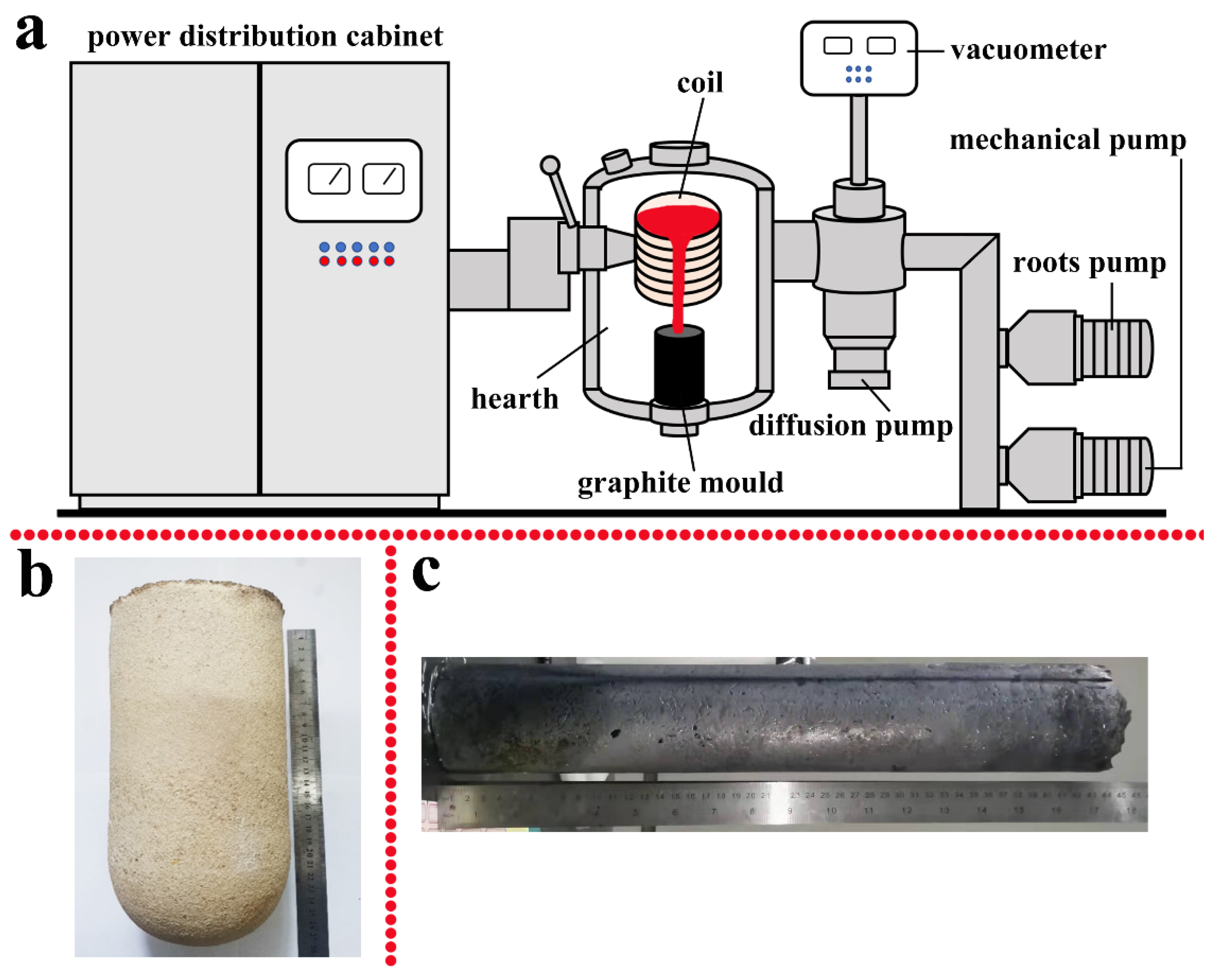
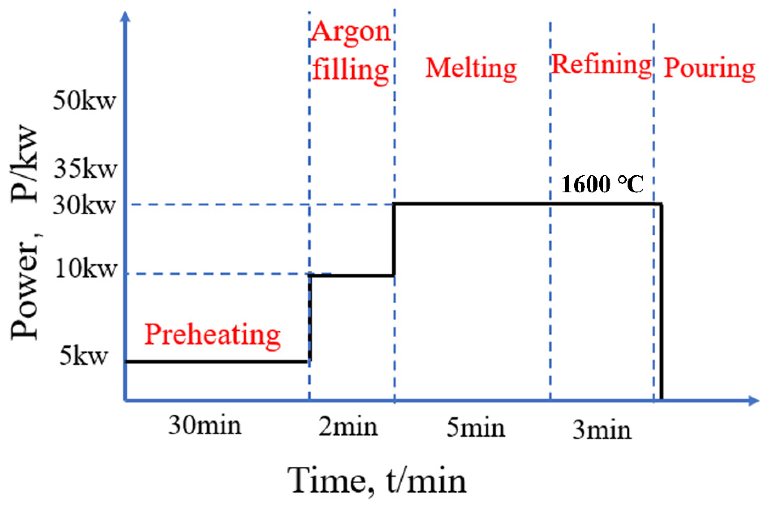
2.1. Melting Process

The ingot with the composition of Ti-46Al-8Nb (at.%) were prepared by vacuum induction melting (VIM) in a 25 Kg-grade in-house U-shaped BaZrO3 crucible. The details of the preparation process of the BaZrO3 crucible can be referred to in the previous work of our research group [34], a simple schematic process is shown in Figure 1. Pure titanium sponge (99.97%), high-purity aluminum ingots (99.99%) and an Al-60Nb (wt.%) intermediate alloy were used as experimental raw materials. Before feeding, the raw materials must be baked at 150 °C for 2 h in a drying oven to fully evaporate the water. Before turning on the diffusion pump, a mechanical pump and a roots pump are used to exhaust the air in the furnace as much as possible. Before the heating cycle, the furnace was evacuated up to less than 0.03 Pa by a diffusion pump, and then backfilled three times with purity argon (99%) in order to minimize the hydrosphere and oxygen content. When the raw material start melting, the furnace was backfilled with purity argon to 0.4 MPa to prevent the evaporation of aluminum. Figure 2 shows a step diagram of the melting process, including the heating power and the required holding time. After reaching the raw material completely melted, the molten metal was poured into a graphite mold with a size of Φ85 mm × 600 mm to obtain a high-Nb containing TiAl-based alloy ingot. The melting temperature was monitored by KB-602 thermocouple and Marathon series dual-color integrated infrared thermometer (Raytek, Santa Cruz, CA, USA).

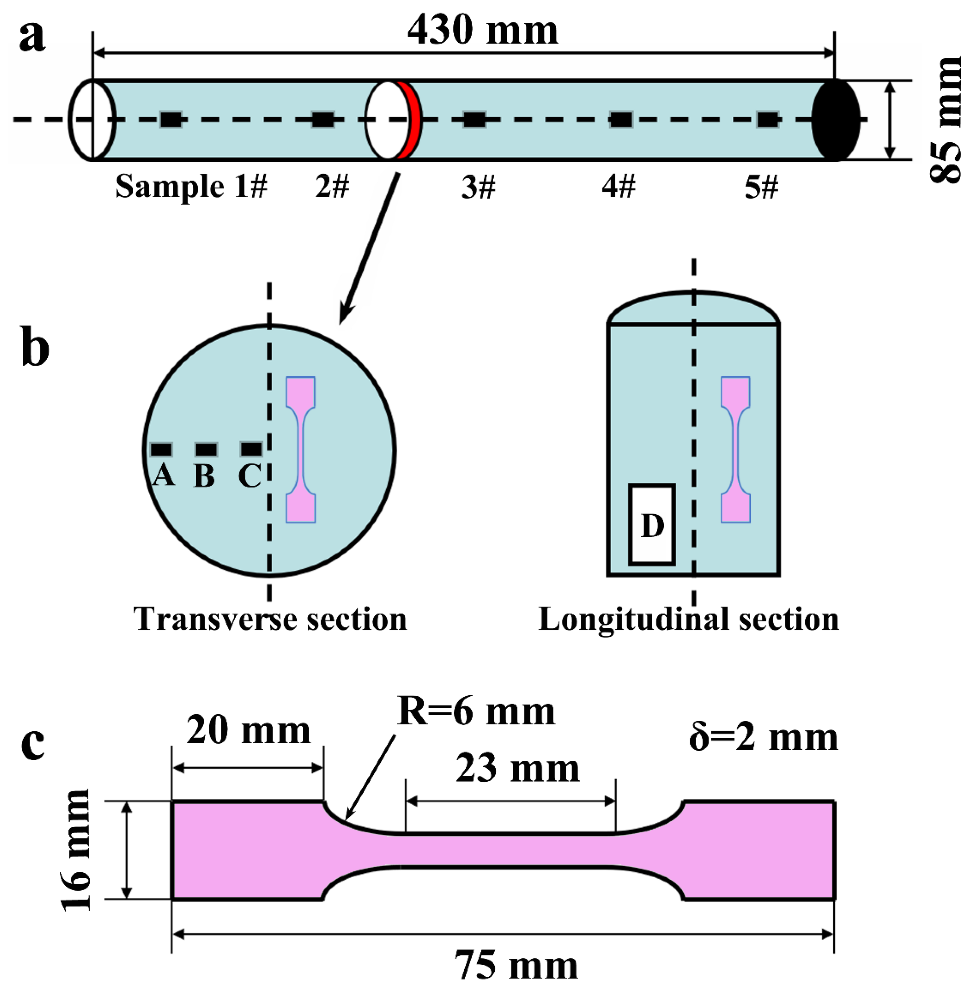
2.2. Sampling and Processing

The cutting and sampling of the ingot is shown in Figure 3. As shown in Figure 3a, samples 1# to 5# were obtained from the inside of the ingot, with a size of 3 mm × 3 mm × 3 mm, and are used to test the oxygen content and chemical composition of the ingot. The 2 mm thin slice was cut along the center of the ingot by wire electrical discharge machine (WEDM-M332) (Suzhou New Spark, Suzhou, China), as shown in Figure 3a, and then the required samples were obtained from the thin slice, as shown in Figure 3b. A, B and C are three metallographic samples with a size of 10 mm × 10 mm × 2 mm from the surface to the core on the transverse section of the ingot. D is the metallographic sample with the size of 50 mm × 20 mm × 2 mm on the longitudinal section. The pink dog-bone shape is the tensile test samples, and the size of the tensile specimen is shown in Figure 3c. The metallographic samples were processed by standard metallographic techniques, first smoothed on sandpaper, then polished with silica suspension (particle size: 0.25 μm), and etched in corrosive agent (H2O:HNO3:HF = 18:1:1) for 10 s.

2.3. Sample Characterization and Testing

The macrostructures were photographed by a digital single lens reflex, and the microstructure of the ingots was characterized by LEICA metallographic microscope (Leica Microsystems GmbH, Wetzlar, Germany) and JSM-6700F scanning electron microscope (SEM) (JEOL Ltd., Tokyo, Japan). Point and line scanning analysis for the alloy ingot were carried out through an energy dispersive spectrometer (EDS) (EDAX Inc., Pleasanton, CA, USA). The oxygen content and chemical composition of the ingots were measured by pulse heating inert gas melting infrared absorption method (TC-436 Nitrogen and oxygen analyzer) (LECO Corporation, St. Joseph, MI, USA) and inductively coupled plasma optical emission spectrometry (ICP-OES) (Thermo Fisher Scientific Inc., Shanghai, China), respectively. The phases of the samples were identified using an X-ray diffractometer (D/Max-2200) (Rigaku Corporation, Tokyo, Japan) with a step size of 1.2°/min over 2θ ranging from 10° to 90°. The tensile properties of the samples were carried out for room-temperature deformation at a constant strain rate of 2.1 × 10⁻³ s−1 by using a Zwick (CMT-100) universal testing machine (Zwick Roell Group, Ulm, Germany).

3. Results and Discussions

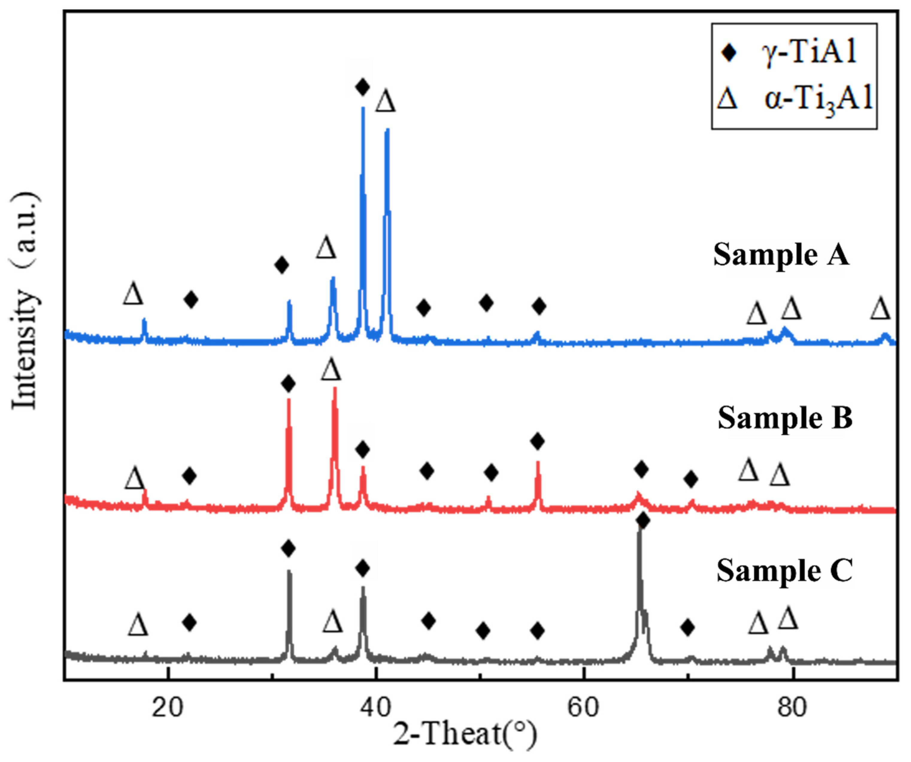
3.1. Chemical Composition and Phases

Since the VIM-BZO technique is used in this study, strong electromagnetic stirring and sufficient superheating can ensure a relatively good chemical homogeneity of the ingot. Analyzing the chemical composition of the ingot, as shown in Table 1, it can be seen that the deviations of Al and Nb content along a 430 mm long central part of the ingot are approximately ±0.39 at.% and ±0.14 at.%, respectively. Compared with the double-melted VAR large ingot (±0.7 at.% Al) [35], the double-melted PAM large ingots (±0.5 at.% Al) [36] and the single-melted ISM large ingot (±0.75 at.% Al) [37], the deviation of Al content of the single-melted VIM-BZO large ingot in this study is undoubtedly encouraging. Overall, the Al content is slightly below the nominal level due to evaporation of Al during the melting process, although 0.6 wt.% Al has been compensated during manufacturing. The contaminating element O mainly comes from the BaZrO3 refractory crucible. According to our previous study [33], the TiAl alloy melt and the BaZrO3 refractory crucible will undergo a dissolution reaction at the interface, and the dissolution equation is as follows:
TiAl ( l ) + χ 2 BaZrO 3 ( s ) TiAl [ χ 2 Zr , χ O ] ( l ) + χ 2 BaO ( l )
According to Equation (1), it can be seen that the local area where the TiAl alloy melt and the BaZrO3 refractory crucible are in contact with the BaZrO3 refractory crucible causes the oxygen concentration to increase due to the dissolution reaction, and the oxygen ions in the high oxygen concentration area in the melt will continuously diffuse to the low oxygen concentration area. It can be seen that the oxygen content of the ingot prepared using the BaZrO3 refractory crucible is slightly less than twice that of the water-cooled copper crucible (about 500~600 ppm) [38]. Considering the chemical activity of titanium at high temperature, this level of oxygen contamination is acceptable and sufficient for industrial applications [39,40]. Liu et al. [41] used vacuum induction melting technology (CaO crucible) combined with Al2O3 mould to single-step centrifugal casting of TiAl-based alloy automotive valves, and the oxygen level of the alloy was 820~2900 ppm. Cast turbocharger wheels and 1 mm thick sheets of TiAl (TNB-V5, Ti-45Al-0.2B-0.2C) alloy, supplied by ACCESS (an independent research center associated with the Technical University of Aachen in Germany), had an oxygen level of around 1200 ppm as determined by GKSS (now renamed Helmholtz-Zentrum Geesthacht), which is twice as high as the raw material [42]. Simbarashe et al. [43] wrote a review on crucibles for induction melting of titanium alloys, and summarized the oxygen level data of various common refractory crucibles used in the melting of TiAl-based alloys, such as Al2O3 (1600~2500 ppm), Y2O3 (600~3300 ppm), MgO (9500~10500 ppm), CaO (1000~7100 ppm), CaZrO3 (1300~7300 ppm), BaZrO3 (650~1300 ppm).
A detailed evaluation of the Ti-Al-Nb ternary system was carried out by Witusiewicz et al. [44] in 2009 and the corresponding TDB file is attached. After analyzing their data in detail, this study used their database as a standard and utilized Pandat software to describe the Ti-Al pseudo-binary phase diagram with 8 at.% Nb concentration, as shown in Figure 4. The Ti-Al-Nb ternary phase diagram evaluated by Witusiewicz et al. indicates that the Ti-46Al-8Nb alloy is mainly composed of γ (TiAl), α2 (Ti3Al) and βo (bcc-B2) phases at room temperature [44]. However, the X-ray diffraction spectra showed that there were only two phases, γ and α2, in the ingot, as shown in Figure 5, which may be due to the fact that the content of β phase is too small to exceed the minimum standard that can be detected by the instrument.
In addition, according to the peak intensity analysis of X-ray diffraction pattern, γ phase is the main phase in the alloy ingot. However, the α2 phase content of sample A near the surface of the ingot is significantly higher than that of sample B in the middle region and sample C in the core, and it shows a decreasing trend. This is mainly due to the fact that the pre-solidified area of the ingot surface contains more high melting point Ti and Nb elements, so that the final solidified core area is rich in Al element. As a result, the content of α2 phase is higher on the ingot surface, while the content of γ phase in the core is increased.

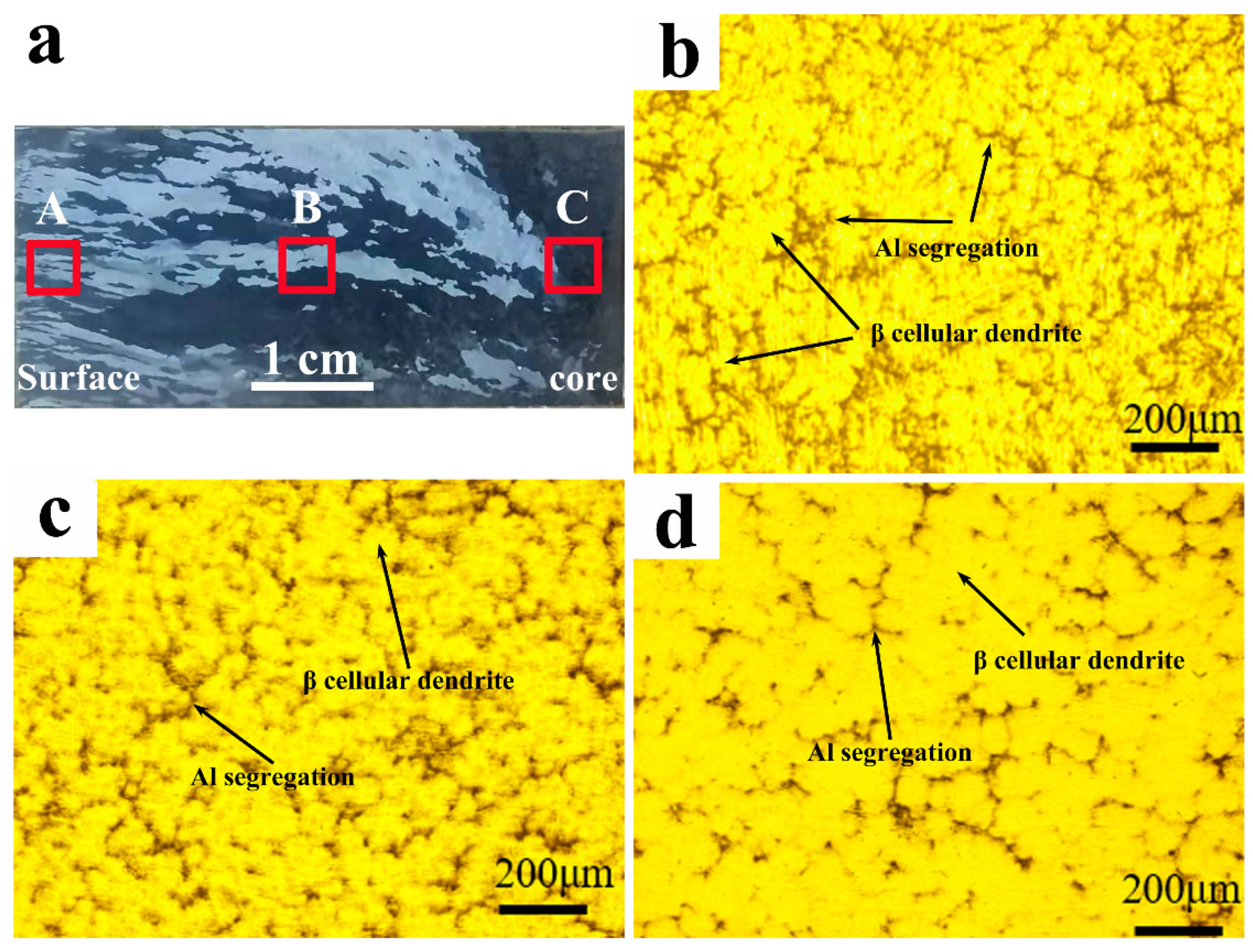
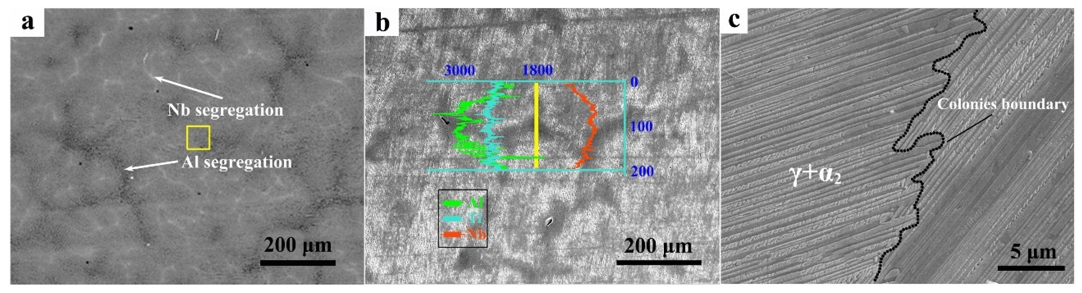
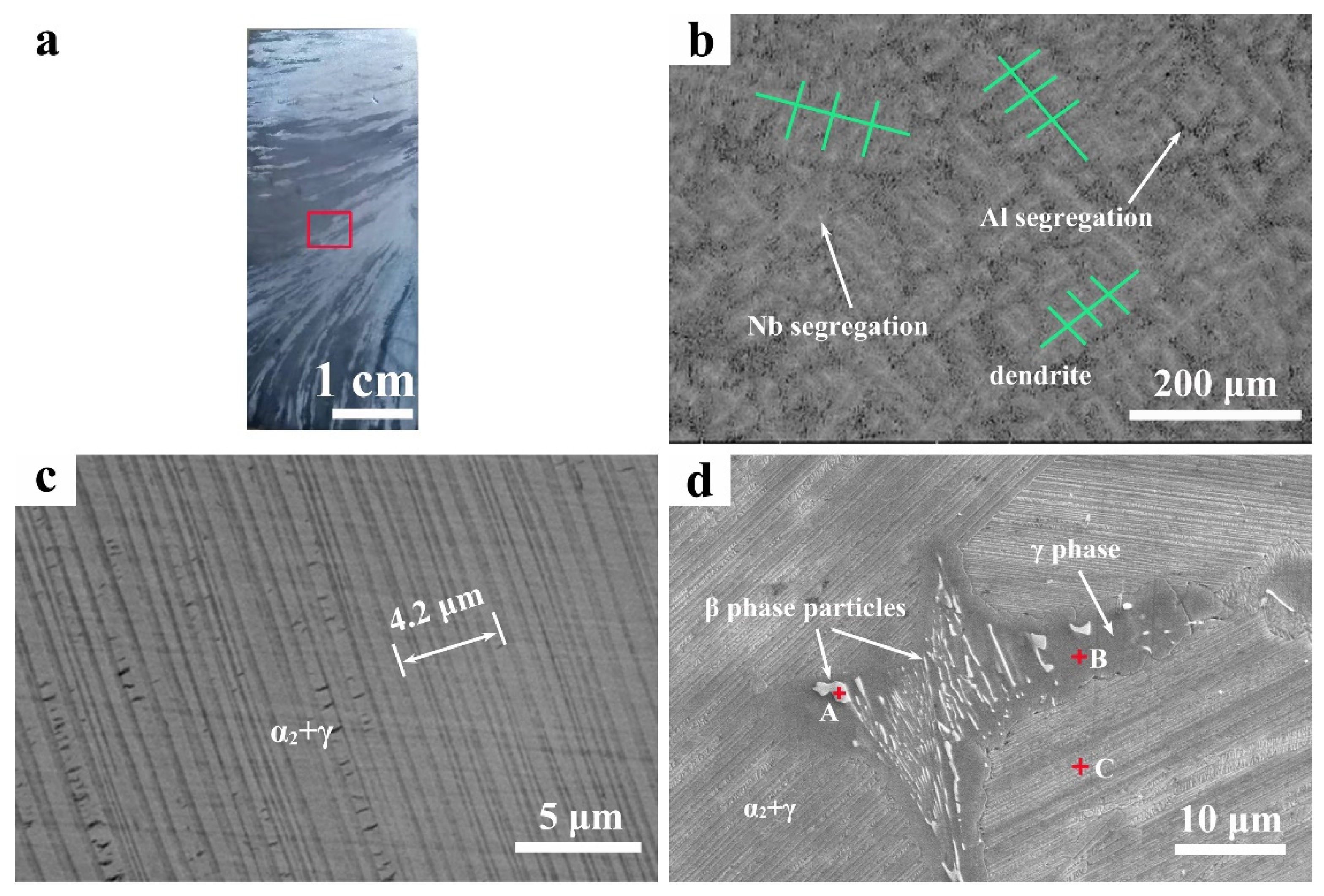
3.2. Structure and Microsegregation

In order to investigate the structure of the Ti-46Al-8Nb alloy ingot prepared by the VIM-BZO technique, the transverse and longitudinal sections of the ingot were analyzed in detail in this study, and the sampling schematic diagram is shown in Figure 3. First, analyzing the transverse section, as shown in Figure 6, the macrostructure shows that the columnar grains with a specific orientation (perpendicular to the central axis and parallel to the heat flow but in the opposite direction) are predominant in the ingot (Figure 6a). According to previous studies [45,46,47], in the absence of grain-refining elements such as B, the solidification structure of TiAl-based alloys usually shows a large difference depending on whether it solidifies via the β phase (β→α, β-solidified TiAl-based alloy) or peritectic via the α phase (L + β→α, peritectic solidified TiAl-based alloy). β-solidified TiAl-based alloys exhibited structures consisting of relatively large equiaxed grains, whereas peritectic solidified TiAl-based alloys showed columnar grains that had grown in the opposite direction to that of heat flow. However, the target alloy in this study shows that it solidifies through the β phase on the phase diagram, as shown by the red solid line in Figure 4, but the actual ingot shows the typical microstructure characteristics of the peritectic solidified TiAl-based alloys. Moreover, the Al content in the ingot that is actually measured is not higher than 46 at.% (Table 1). Therefore, it can be determined that the actual solidification pathway has shifted to the high Al content in the diagram, as shown by the dotted green line in Figure 4, which may be caused by the following three reasons: (i) Caused by the non-equilibrium solidification process; (ii) The influence of oxygen content. Oxygen is the stabilizer of the α phase, which will expand the α phase field to the low Al content in the diagram. The literature shows that 1 at.% O is equivalent to 3.57~4.58 at.% Al in the TiAl-based alloy [41]; (iii) Since the pre-solidified β phase contains more Nb and Ti, the remaining liquid phase is locally enriched in Al. If the Al content reaches the composition range of the peritectic reaction, peritectic solidification will occur instead of β solidification.
In addition, the grains near the surface of the ingot are smaller than those in the core. The dendritic morphologies of different regions on the transverse section are shown in Figure 6b–d, it can be seen that the cellular dendrite region is bright and the interdendritic zone is dark in contrast. This is mainly due to the segregation of Al and Nb. As described of the phase diagram in Figure 4, the primary phase is the β phase (L→L + β), so the bright in contrast is the β cellular dendrite. When the temperature falls into the peritectic reaction, it will lead to the redistribution of Al and Nb elements through the peritectic transformation L + β→α, where Al diffuses into the α phase and the β stabilizer Nb is pushed in the opposite direction. This phenomenon is more obvious in Figure 7a, except for the dark area of Al segregation, the “white network” inside the dendrite enveloped by the gray area is Nb segregation. Analyzing the line scan profile of the black region along the yellow solid line, as shown in Figure 7b, it can be clearly seen that the peak intensity of Al element in this area increases, while the peak intensity of Nb element decreases. Figure 7c is a local magnification of the yellow solid frame area in Figure 7a, which is a full lamellar structure composed of γ and α2 phases, and the colonies boundary is clearly distinguishable.
The solidification structure of the longitudinal section of the ingot was characterized, as shown in Figure 8. At the bottom area of the ingot, since the downward direction is the main heat flow direction, and the left direction is the secondary heat flow direction, as shown by the arrows, the growth direction of the columnar grain is opposite to the heat flow direction, that is, it grows in the upper-right direction (Figure 8a). Figure 8b is the corresponding microstructures in the red frame of Figure 8a. The segregation situation is similar to that of the transverse section, but the dendrite morphology in Figure 8b is different from the transverse section, which is mainly caused by the different selected sections. It can be seen that the primary and secondary dendrite arms are about 90°, indicating that they are β dendrites, which is consistent with the conclusion given by the phase diagram (Figure 4). Figure 8c shows a local magnification of Figure 8b, and it can be seen that the structure of the alloy ingot is a full lamellar structure composed of γ and α2 phases, and the thickness of the lamellae is approximately 0.53 μm (eight groups of lamellae with a total of 4.2 μm).
In Figure 8d, a group of white particles are aggregated at the triple conjunction of colonies, and the EDS point scan data analysis showed that the Nb content of this particle is much higher than that in the matrix (Table 2). Therefore, it can be determined that these white particles are caused by Nb segregation, and the high Nb content leads to the local area falling into the βo + γ + α2 three phase field or the βo + γ two phase field, so these white particles can be considered as βo (bcc-B2) phase. Since the β-phase particles are rich in Nb, the Al is rejected to the peripheries of the particles and surround them, forming a new phase (Figure 8d). This phase was considered to be a γ phase by EDS analysis (Table 2).

3.3. Mechanical Properties

Considering the anisotropy of ingot microstructure (as shown in Figure 7a and Figure 8a), in this study, the tensile properties of Ti-46Al-8Nb alloy ingot prepared by the VIM-BZO technique are investigated by sampling from transverse and longitudinal sections respectively. The schematic diagram of the transverse section and longitudinal section including the microstructure is shown in Figure 9a. Therefore, the direction of loading and stress in the transverse-cut samples are roughly consistent with the orientation of the columnar grains, while the direction of loading and stress in the longitudinal-cut samples are perpendicular to the orientation of the columnar grains. Compared with the transverse-cut samples, the mechanical properties of the longitudinal-cut samples are better because more grain boundaries exist in the longitudinal-cut samples. The role of grain boundaries has two aspects [48]: (i) grain boundaries are obstacles to the movement of dislocations; (ii) grain boundaries are the places where dislocations gather, so the more grain boundaries there are, the more obstacles hinder the movement of dislocations, and the higher the density of dislocations, the more aggregated they are, resulting in an increase in strength. Meanwhile, grain boundaries can also hinder the crack propagation, so that the plasticity and toughness of the material are improved. The mechanism by which grain boundaries hinder crack propagation can be explained from the following two aspects [49,50]: (i) grain boundaries can obstruct the movement of dislocations emitted from the crack tip; (ii) the change of propagation direction due to grain boundaries needs to dissipate more energy. The blockage of dislocation and crack propagation by grain boundaries is the main reason for the significant difference of tensile properties between transverse-cut samples and longitudinal-cut samples of the ingot. As shown in Figure 9b, which showed that the room temperature strength of one of the longitudinal-cut samples is as high as 700 MPa, and the fracture elongation is 1.1%. However, the tensile properties of the transverse-cut samples are significantly reduced, and one of the strength and fracture elongation are 375 MPa and 0.52%, respectively. Figure 9c,d are the fracture morphologies of the transverse-cut tensile sample and the longitudinal-cut tensile sample, respectively. A series of cleavage can be seen in the fractures in Figure 9c,d, but the presence of dimples can also be seen in Figure 9d. Therefore, it can be inferred that the transverse-cut tensile sample may be cleavage fracture, while the longitudinal-cut tensile sample may be quasi-cleavage fracture.
The tensile properties of the alloy ingots in this study were compared with those of high Nb-containing TiAl-based alloys prepared by different processes reported in the literature, as shown in Table 3. Both the tensile strength and the elongation of the longitudinal-cut samples in this work are better than those of the Ti-46Al-8Nb alloy prepared by Saage et al. [51], which were obtained by a series of complex treatments. Xiao et al. [52] obtained an ingot with a tensile strength of 666 ± 31 MPa and a corresponding elongation of 0.56 ± 0.15% by adding 0.15 at.% nano-Y2O3 particles to the alloy matrix. In comparison, the ingots obtained in one shot by the VIM-BZO technique in this study have better tensile properties in the longitudinal section. The alloy obtained by Liu et al. [53] through a series of complex processes (the PM technique to homogenize and refine the microstructure, the HIP technique to reduce casting defects, and the HR technique to induce work hardening) has a tensile strength of 875 MPa and a corresponding elongation of 0.76%. By contrast, the tensile strength is 175 MPa higher than that of the longitudinal-cut sample in this study, but the fracture elongation is 0.34% lower.
In general, VAR, ISM and PAM ingots often require very complicated subsequent processing due to their chemical inhomogeneity and casting defects, which will undoubtedly increase a lot of costs. In contrast, the ingot obtained by using the VIM-BZO technique has considerable tensile properties in the longitudinal direction without subsequent processing, but is poorer in the transverse direction. Obviously, such anisotropic tensile properties are difficult to meet the expectations of practical applications. In the future, we will perform a series of subsequent treatments on the ingot, such as HIP, hot rolling or heat treatment, in order to obtain a uniform and refined microstructure, and finally optimize the mechanical properties of the alloy.

4. Conclusions

In this study, Ti-46Al-8Nb alloy ingots beyond laboratory scale were prepared by the vacuum induction melting technique based on a BaZrO3 refractory crucible. The following conclusions can be drawn:
(1)
By refining at 1600 °C for 3 min, a high quality and high Nb-containing TiAl-based alloy round bar ingot with a diameter of 85 mm and a length of 430 mm was finally obtained.
(2)
The deviations of Al and Nb content along a 430 mm long central part of the ingot are approximately ±0.39 at.% and ±0.14 at.%, and the oxygen content in the ingot can be controlled at around 1000 ppm.
(3)
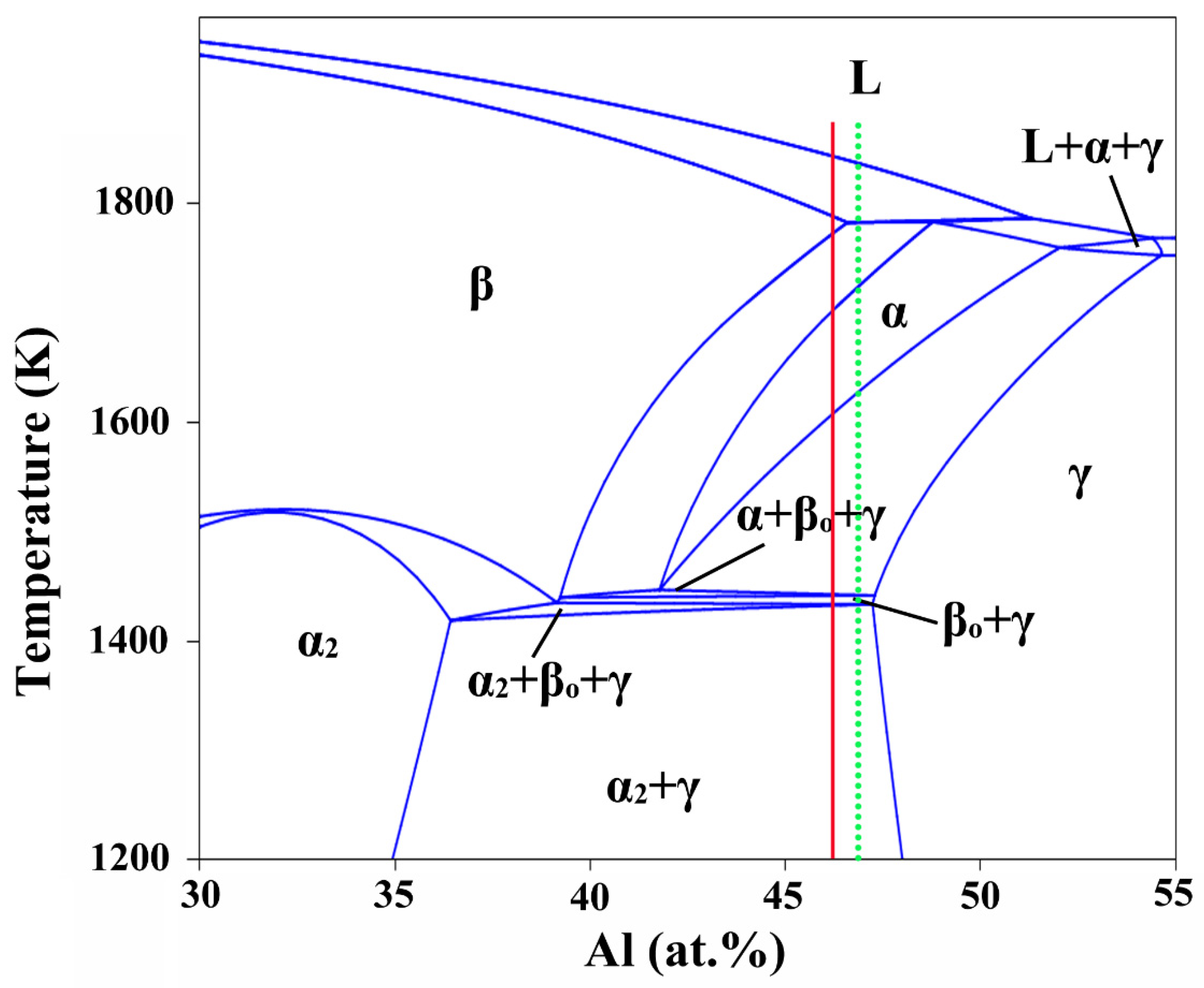
During the solidification process of the alloy ingot, the primary phase is the β phase, which subsequently undergoes a peritectic reaction via the α phase instead of solidified via the β phase.
(4)
The structure of the alloy ingot is a full lamellar structure composed of γ and α2 phases, and the thickness of the lamellae is approximately 0.53 μm. The content of the α2 phase near the surface of the ingot is higher than that in the middle region and the core region, and it shows a decreasing relationship. In addition, there are some Nb-rich β phase particles surrounded by γ-phase particles, and these Nb-rich β-phase particles aggregat at the triple conjunction of colonies.
(5)
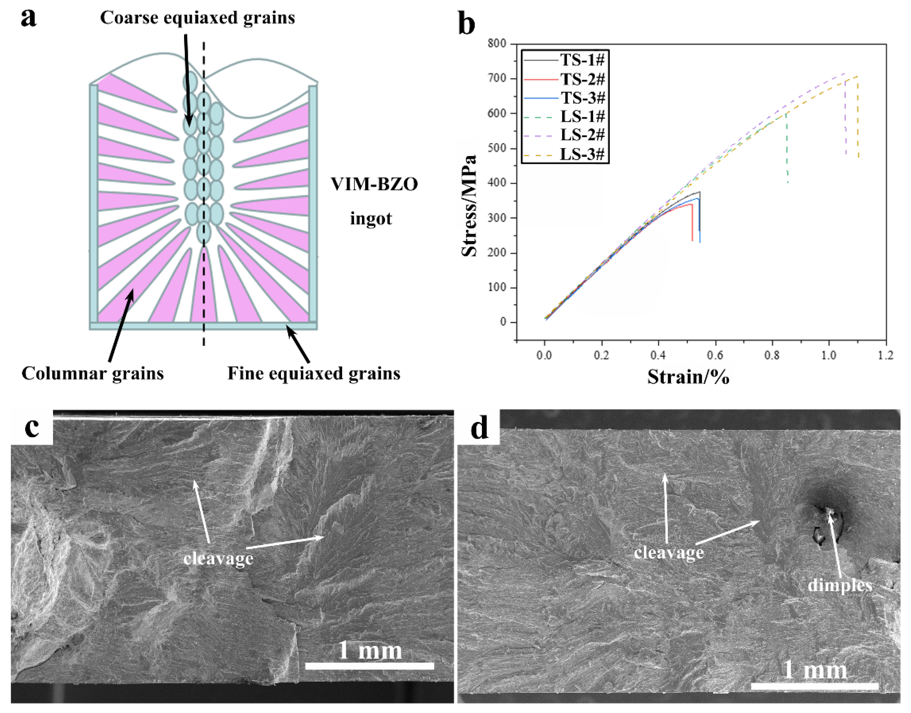
The tensile properties of transverse-cut samples are significantly better than those of longitudinal-cut samples, with a tensile strength of up to 700 MPa and a corresponding fracture elongation of 1.1%.

Author Contributions

Conceptualization, X.L.; Data curation, B.D., Y.Y. and R.Z.; Formal analysis, B.D.; Funding acquisition, C.L.; Investigation, L.M., Y.Y. and X.Z.; Methodology, L.M., X.Z. and L.J.; Project administration, Q.F., X.L. and G.C.; Resources, H.L. and L.J.; Software, B.D. and Q.F.; Supervision, G.C. and C.L.; Validation, C.L.; Visualization, B.D. and R.Z.; Writing—original draft, B.D.; Writing—review & editing, C.L. All authors have read and agreed to the published version of the manuscript.

Funding

This work was supported by the National Natural Science Foundation of China (Contract: U1860203); Independent Research and Development Project of State Key Laboratory of Advanced Special Steel, Shanghai Key Laboratory of Advanced Ferrometallurgy, Shanghai University (SKLASS 2020-Z11), the Science and Technology Commission of Shanghai Municipality (No. 19DZ2270200); National Natural Science Foundation of China (Nos. 52022054; 51974181); the Program for Professor of Special Appointment (Eastern Scholar) at Shanghai Institutions of Higher Learning (TP2019041).

Institutional Review Board Statement

Not applicable.

Informed Consent Statement

Not applicable.

Data Availability Statement

Available upon request.

Acknowledgments

We would like to thank the research group of Han Dong at the School of Materials Science and Engineering, Shanghai University for the support of optical microscopy. Thanks for the support of scanning electron microscopy provided by Shanghai Dianji University. Thanks to Cheng Biao, Humboldt University of Berlin for her language support. We also would like to thank to the anonymous reviewers of this paper for their constructive comments.

Conflicts of Interest

The authors declare no conflict of interest.

References

  1. Wu, X. Review of alloy and process development of TiAl alloys. Intermetallics 2006, 14, 1114–1122. [Google Scholar] [CrossRef]
  2. Dimiduk, D.M. Gamma titanium aluminide alloys—An assessment within the competition of aerospace structural materials. Mater. Sci. Eng. A 1999, 263, 281–288. [Google Scholar] [CrossRef]
  3. Clemens, H.; Wallgram, W.; Kremmer, S.; Güther, V.; Otto, A.; Bartels, A. Design of Novel β-Solidifying TiAl Alloys with Adjustable β/B2-Phase Fraction and Excellent Hot-Workability. Adv. Eng. Mater. 2008, 10, 707–713. [Google Scholar] [CrossRef]
  4. Clemens, H.; Mayer, S. Design, Processing, Microstructure, Properties, and Applications of Advanced Intermetallic TiAl Alloys. Adv. Eng. Mater. 2013, 15, 191–215. [Google Scholar] [CrossRef]
  5. Hu, D. Effect of composition on grain refinement in TiAl-based alloys. Intermetallics 2001, 9, 1037–1043. [Google Scholar] [CrossRef]
  6. Shida, Y.; Anada, H. The effect of various ternary additives on the oxidation behavior of TiAl in high-temperature air. Oxid. Met. 1996, 45, 197–219. [Google Scholar] [CrossRef]
  7. Yoshihara, M.; Miura, K. Effects of Nb addition on oxidation behavior of TiAl. Intermetallics 1995, 3, 357–363. [Google Scholar] [CrossRef]
  8. Güther, V.; Allen, M.; Klose, J.; Clemens, H. Metallurgical processing of titanium aluminides on industrial scale. Intermetallics 2018, 103, 12–22. [Google Scholar] [CrossRef]
  9. Foroozmehr, A.; Kermanpur, A.; Ashrafizadeh, F.; Kabiri, Y. Effects of thermo-mechanical parameters on microstructure and mechanical properties of Ti-50 at %Ni shape memory alloy produced by VAR method. Mater. Sci. Eng. A 2012, 535, 164–169. [Google Scholar] [CrossRef]
  10. Mi, J.; Harding, R.A.; Wickins, M.; Campbell, J. Entrained oxide films in TiAl castings. Intermetallics 2003, 11, 377–385. [Google Scholar] [CrossRef]
  11. Kim, Y.W.; Rosenberger, A.; Dimiduk, D.M. Microstructural changes and estimated strengthening contributions in a gamma alloy Ti–45Al–5Nb pack-rolled sheet. Intermetallics 2009, 17, 1017–1027. [Google Scholar] [CrossRef]
  12. Gomes, F.; Barbosa, J.; Ribeiro, C.S. Induction melting of γ-TiAl in CaO crucibles. Intermetallics 2008, 16, 1292–1297. [Google Scholar] [CrossRef]
  13. Lapin, J.; Gabalcová, Z.; Pelachová, T. Effect of Y2O3 crucible on contamination of directionally solidified intermetallic Ti-46Al-8Nb alloy. Intermetallics 2011, 19, 396–403. [Google Scholar] [CrossRef]
  14. Subbarao, E.C.; Sutter, P.H.; Hrizo, J. Defect Structure and Electrical Conductivity of ThO2-Y2O3 Solid Solutions. J. Am. Ceram. Soc. 1965, 48, 443–446. [Google Scholar] [CrossRef]
  15. Li, C.H.; He, J.; Wei, C.; Wang, H.B.; Lu, X.G. Solidification and Interface Reaction of Titanium Alloys in the BaZrO3 Shell-Mould. Mater. Sci. Forum 2015, 828–829, 106–111. [Google Scholar] [CrossRef]
  16. Li, C.H.; Gao, Y.H.; Lu, X.G.; Ding, W.Z.; Ren, Z.M.; Deng, K. Interaction between the Ceramic CaZrO3 and the Melt of Titanium Alloys. Adv. Sci. Technol. 2011, 70, 136–140. [Google Scholar]
  17. Tetsui, T.; Kobayashi, T.; Ueno, T.; Harada, H. Consideration of the influence of contamination from oxide crucibles on TiAl cast material, and the possibility of achieving low-purity TiAl precision cast turbine wheels. Intermetallics 2012, 31, 274–281. [Google Scholar] [CrossRef]
  18. Barbosa, J.J.; Ribeiro, C.S. Influence of crucible material on the level of contamination in TiAl using induction melting. Int. J. Cast Met. Res. 2000, 12, 293–301. [Google Scholar] [CrossRef]
  19. Čegan, T.; Szurman, I.; Kursa, M.; Holesinsky, J.; Vontorova, J. Preparation of TiAl-based alloys by induction melting in graphite crucibles. Kov. Mater. 2015, 53, 69–78. [Google Scholar]
  20. Chapin, E.; Friske, W. A Metallurgical Evaluation of Refractory Compounds for Containing Molten Titanium: I. Oxides. Nav. Res. Lab. Rept. 2015. Available online: https://www.osti.gov/biblio/4400730 (accessed on 29 January 2022).
  21. Kuang, J.P.; Harding, R.A.; Campbell, J. A study of refractories as crucible and mould materials for melting and casting γ-TiAl alloys. Int. J. Cast Met. Res. 2001, 13, 277–292. [Google Scholar] [CrossRef]
  22. Gomes, F.; Puga, H.; Barbosa, J.; Ribeiro, C.S. Effect of melting pressure and superheating on chemical composition and contamination of yttria-coated ceramic crucible induction melted titanium alloys. J. Mater. Sci. 2011, 46, 4922–4936. [Google Scholar] [CrossRef] [Green Version]
  23. Zhang, H.R.; Tang, X.X.; Zhou, L.; Gao, M.; Zhou, C.G.; Zhang, H. Interactions between Ni-44Ti-5Al-2Nb-Mo alloy and oxide ceramics during directional solidification process. J. Mater. Sci. 2012, 47, 6451–6458. [Google Scholar] [CrossRef]
  24. Zhang, H.; Tang, X.; Zhou, C.; Zhang, H.; Zhang, S. Comparison of directional solidification of γ-TiAl alloys in conventional Al2O3 and novel Y2O3-coated Al2O3 crucibles. J. Eur. Ceram. Soc. 2013, 33, 925–934. [Google Scholar] [CrossRef]
  25. Kostov, A.; Friedrich, B. Predicting thermodynamic stability of crucible oxides in molten titanium and titanium alloys. Comput. Mater. Sci. 2006, 38, 374–385. [Google Scholar] [CrossRef]
  26. Lapin, J.; Gabalcová, Z. Solidification behaviour of TiAl-based alloys studied by directional solidification technique. Intermetallics 2011, 19, 797–804. [Google Scholar] [CrossRef]
  27. Ding, H.; Zhang, H.; Wang, Q.; Chen, R.; Guo, J.; Fu, H. Effect of Y2O3 particles on the fracture toughness of directionally solidified TiAl-based alloys. Mater. Sci. Eng. A 2017, 703, 108–115. [Google Scholar] [CrossRef]
  28. Trivedi, P.; Patankar, S.; Baburaj, E.G. Formation of Al-Y Oxide during Processing of γ-TiAl. J. Alloys Compd. 2002, 340, 231–235. [Google Scholar] [CrossRef]
  29. Wu, Y.; Hwang, S.K. The effect of yttrium on microstructure and dislocation behavior of elemental powder metallurgy processed TiAl-based intermetallics. Mater. Lett. 2004, 58, 2067–2072. [Google Scholar] [CrossRef]
  30. Chen, G.; Gao, P.; Kang, J.; Li, B.; Ali, W.; Qin, Z.; Lu, X.; Li, C. Improved stability of BaZrO3 refractory with Y2O3 additive and its interaction with titanium melts. J. Alloys Compd. 2017, 726, 403–409. [Google Scholar] [CrossRef]
  31. Chen, G.; Lan, B.; Xiong, F.; Gao, P.; Zhang, H.; Lu, X.; Li, C. Pilot-scale experimental evaluation of induction melting of Ti-46Al-8Nb alloy in the fused BaZrO3 crucible. Vacuum 2019, 159, 293–298. [Google Scholar] [CrossRef]
  32. Li, K.; Chen, G.; Hao, Z.; Ali, W.; Li, C. Microstructure evolution of directionally solidified Ti-46Al-8Nb alloy in the BaZrO3-based mould. Mater. Res. Express 2018, 5, 116529. [Google Scholar] [CrossRef]
  33. Chen, G.; Kang, J.; Lan, B.; Gao, P.; Lu, X.; Li, C. Evaluation of Ca-doped BaZrO3 as the crucible refractory for melting TiAl alloys. Ceram. Int. 2018, 44, 12627–12633. [Google Scholar] [CrossRef]
  34. Zhang, Z.; Zhu, K.; Liu, L.; Wu, G.; Chen, G. Preparation of BaZrO3 Crucible and Its Interfacial Reaction with Molten Titanium Alloys. J. Chin. Ceram. Soc. 2013, 41, 1278–1283. [Google Scholar]
  35. Khalid, F.; Edmonds, D. The Processing, Properties and Applications of Metallic Ceramic Materials. Proc. IRC Birm. 1992, 14, 5. [Google Scholar]
  36. Blackburn, M.J.; Malley, D.R. Plasma arc melting of titanium alloys. Mater. Des. 1993, 14, 19–27. [Google Scholar] [CrossRef]
  37. Hu, D.; Godfrey, A.; Blenkinsop, P.A.; Loretto, M.H. Processing-property-microstructure relationships in TiAl-based alloys. Metall. Mater. Trans. A 1998, 29, 919–925. [Google Scholar] [CrossRef]
  38. Yanqing, S.; Jingjie, G.; Jun, J.; Guizhong, L.; Yuan, L. Composition control of a TiAl melt during the induction skull melting (ISM) process. J. Alloys Compd. 2002, 334, 261–266. [Google Scholar] [CrossRef]
  39. Zollinger, J.; Lapin, J.; Daloz, D.; Combeau, H. Influence of oxygen on solidification behaviour of cast TiAl-based alloys. Intermetallics 2007, 15, 1343–1350. [Google Scholar] [CrossRef]
  40. Friedrich, B.; Morscheiser, J.; Lochbichler, C. Potential of ceramic crucibles for melting of titanium-alloys and gamma-titaniumaluminide. Int. Feuerfestkolloquium 2008, 15, 16. [Google Scholar]
  41. Liu, K.; Ma, Y.C.; Gao, M.; Rao, G.B.; Li, Y.Y.; Wei, K.; Wu, X.; Loretto, M.H. Single step centrifugal casting TiAl automotive valves. Intermetallics 2005, 13, 925–928. [Google Scholar] [CrossRef]
  42. Appel, H.F.; Paul, J.; Oehring, M. Gamma Titanium Aluminide Alloys: Science and Technology; John Wiley & Sons: Hoboken, NJ, USA, 2011. [Google Scholar]
  43. Fashu, S.; Lototskyy, M.; Davids, M.W.; Pickering, L.; Linkov, V.; Tai, S.; Renheng, T.; Fangming, X.; Fursikov, P.V.; Tarasov, B.P. A review on crucibles for induction melting of titanium alloys. Mater. Des. 2020, 186, 108295. [Google Scholar] [CrossRef]
  44. Witusiewicz, V.T.; Bondar, A.A.; Hecht, U.; Velikanova, T.Y. The Al-B-Nb-Ti system: IV. Experimental study and thermodynamic re-evaluation of the binary Al-Nb and ternary Al-Nb-Ti systems. J. Alloys Compd. 2009, 472, 133–161. [Google Scholar] [CrossRef]
  45. McCullough, C.; Valencia, J.J.; Levi, C.G.; Mehrabian, R. Phase equilibria and solidification in Ti-Al alloys. Acta Metall. 1989, 37, 1321–1336. [Google Scholar] [CrossRef]
  46. Larsen, D.E.; Kampe, S.; Christodoulou, L. Effect of XDTM TiB2 Volume Fraction on the Microstructure of a Cast Near-gamma titanium aluminide alloy. MRS Online Proc. Libr. 1990, 194, 285–292. [Google Scholar] [CrossRef]
  47. Imayev, R.M.; Imayev, V.M.; Oehring, M.; Appel, F. Alloy design concepts for refined gamma titanium aluminide based alloys. Intermetallics 2007, 15, 451–460. [Google Scholar] [CrossRef]
  48. Bonetti, E.; Pasquini, L.; Sampaolesi, E. The influence of grain size on the mechanical properties of nanocrystalline aluminium. Nanostruct. Mater. 1997, 9, 611–614. [Google Scholar] [CrossRef]
  49. Zeng, Z.; Li, X.; Lu, L.; Zhu, T. Fracture in a thin film of nanotwinned copper. Acta Mater. 2015, 98, 313–317. [Google Scholar] [CrossRef] [Green Version]
  50. Hertzberg, R.W.; Vinci, R.P.; Hertzberg, J.L. Deformation and Fracture Mechanics of Engineering Materials; John Wiley & Sons: Hoboken, NJ, USA, 2020. [Google Scholar]
  51. Saage, H.; Huang, A.J.; Hu, D.; Loretto, M.H.; Wu, X. Microstructures and tensile properties of massively transformed and aged Ti46Al8Nb and Ti46Al8Ta alloys. Intermetallics 2009, 17, 32–38. [Google Scholar] [CrossRef]
  52. Xiao, S.; Guo, Y.; Liang, Z.; Wang, X.; Yang, J.; Wang, X.; Xu, L.; Tian, J.; Chen, Y. The effect of nano-Y2O3 addition on tensile properties and creep behavior of as-cast TiAl alloy. J. Alloys Compd. 2020, 825, 153852. [Google Scholar] [CrossRef]
  53. Liu, Y.; Liang, X.; Liu, B.; He, W.; Li, J.; Gan, Z.; He, Y. Investigations on processing powder metallurgical high-Nb TiAl alloy sheets. Intermetallics 2014, 55, 80–89. [Google Scholar] [CrossRef]
Figure 1. Schematic diagram of the Ti-46Al-8Nb alloy melting process. (a) Schematic of a vacuum induction melting furnace; (b) BaZrO3 refractory crucible; (c) Obtained Ti-46Al-8Nb alloy ingot.
Metals 12 00524 g001
Figure 2. The melting power and corresponding holding time.
Metals 12 00524 g002
Figure 3. Schematic diagram of sampling. (a) Schematic of the Ti-46Al-8Nb alloy ingot; (b) 2 mm thick transverse slice and ingot cut in half longitudinally; (c) Tensile specimen and its corresponding sizes.
Metals 12 00524 g003
Figure 4. Pseudo-binary phase diagram of Ti-Al with 8 at.% Nb concentration [44].
Metals 12 00524 g004
Figure 5. X-ray diffraction spectra of the ingot obtained at different location. The locations of samples A, B and C are shown in Figure 3.
Metals 12 00524 g005
Figure 6. Structure of the transverse section of the alloy ingot. (a) Macrograph from surface to core; (bd) are the metallographic structures of sample A, sample B and sample C, respectively.
Metals 12 00524 g006
Figure 7. The microstructure characterization and line scan analysis of the transverse section were carried out under SEM-EDS. (a,b) are the microtopography and line scan analysis of the transverse section (Sample B), respectively; (c) is a magnified view of the area in the yellow solid frame in (a).
Metals 12 00524 g007
Figure 8. Structure of the longitudinal section of the alloy ingot. (a) Macrograph of longitudinal section, and the sampling location is shown in Figure 3; (bd) are the SEM diagram of longitudinal section.
Metals 12 00524 g008
Figure 9. Tensile properties and fracture morphologies of longitudinal and transverse sections. (a) Structural diagram of longitudinal section of the VIM-BZO alloy ingot; (b) stress-strain curve, LS: longitudinal section; TS: transverse section; (c,d) are the fracture morphologies of the transverse-cut tensile sample and the longitudinal-cut tensile sample, respectively.
Metals 12 00524 g009
Table 1. Chemical composition of the produced Ti-46Al-8Nb alloy ingot.
ElementsAl (at.%)Nb (at.%)O (ppm)Ti (at.%)
Sample 1#45.017.971053Bal.
Sample 2#45.407.90991Bal.
Sample 3#45.327.75975Bal.
Sample 4#45.537.841021Bal.
Sample 5#45.767.981047Bal.
Deviation x ¯ − xmin x ¯ − xmax x ¯ − xmin x ¯ − xmax//
+0.39−0.36+0.14−0.09
Target468/Bal.
Note: the oxygen content in the raw material is about 150 ppm (mass fraction).
Table 2. EDS analysis of the points in Figure 8d.
PointUnitElement
TiAlNbOZr
Awt.%50.0722.7124.370.452.39
at.%46.7137.6211.721.271.17
Bwt.%47.8633.5016.130.302.20
at.%38.9148.356.760.740.94
Cwt.%50.9729.4717.090.411.90
at.%44.3845.557.671.080.87
Table 3. Room temperature mechanical properties of the high Nb containing TiAl-based alloys.
AlloysMelting TechniquesProcessing TechniquesTensile Strength
(MPa)
Elongation
(%)
References
Ti-46Al-8NbDM-PAMSBQ571 ± 180.43[51]
Ti-45Al-6Nb-2.5V-0.15Y2O3ISMCasting666 ± 310.56 ± 0.15[52]
Ti-45Al-7Nb-0.3WVAR-PMHIP/HR8750.76[53]
Ti-46Al-8Nb (longitudinal section)VIM-BZOCasting7001.1This work
Ti-46Al-8Nb (transverse section)VIM-BZOCasting3750.52This work
Note: DM (double melted); SQB (1360 °C /1 h solution treatment, then quenched into a salt bath at 850 °C, finally air-cooled to room temperature); VAR-PM (The triple melting VAR ingot is used as the electrode to be atomized by the plasma rotating electrode processing to prepare the alloy powder, and then the as-prepared powder was filled into a stainless steel tank, and finally sealed and degassed at 500 °C for 12 h, PM: powder metallurgy); HIP/HR (Hot isostatic pressing process was conducted at a temperature of 1250 °C, pressure of 150 MPa for 5 h, then hot rolling was carried out after holding at 1280 °C for 1 h, the rolling speed is 40 mm/s, reduction per pass is about 10%, the total reduction were 43%).
Publisher’s Note: MDPI stays neutral with regard to jurisdictional claims in published maps and institutional affiliations.

