Article

Three-Dimensional Morphology and Analysis of Widmanstätten Sideplates Ferrite

1
College of Metallurgy and Energy, North China University of Science and Technology, Tangshan 063210, China
2
Hebei Province High Quality Steel Continuous Casting Engineering Technology Research Center, Tangshan 063210, China
3
Comprehensive Testing and Analyzing Center, North China University of Science and Technology, Tangshan 063210, China
4
State Key Laboratory of Advanced Metallurgy, University of Science and Technology Beijing, Beijing 100083, China
*
Author to whom correspondence should be addressed.
Metals 2022, 12(3), 523; https://doi.org/10.3390/met12030523
Submission received: 1 March 2022 / Revised: 18 March 2022 / Accepted: 19 March 2022 / Published: 21 March 2022

Abstract

:
The three-dimensional (3D) morphology and crystal structure of Widmanstätten sideplate ferrite were simulated using a focused ion beam (FIB) scanning electron microscope equipped with electron backscatter diffraction (EBSD). The primary Widmanstätten sideplates nucleated and grew directly at the austenite grain boundary (GB). A certain included angle between the sideplates and the austenite GB was observed. The sideplates grew approximately parallel to the grain, and were separated by a small-angle GB. The primary Widmanstätten sideplates are best described as “∃” shaped, with a long intermediate ferrite strip. The interface with the austenite GB was smooth and flat, and the sideplate surface contained pits and holes. The secondary Widmanstätten sideplates nucleated and grew on the surface of the proeutectoid GB ferrite, with the sideplates and GB ferrite perpendicular to each other. Sideplates parallel to one another grew into the grain, and were separated by small-angle GB. The 3D morphology was distinguished by its “comb” shape. The sideplates’ tail was clustered and its front end remained sharp. The contact side of the GB ferrite was smooth and flat. The surface contained several uneven pits and defects.

1. Introduction

When hypoeutectoid steel is cooled at a fast rate at high temperatures, proeutectoid ferrite grows from the vicinity of the austenite grain boundary (GB) toward the ingrain along certain habits, forming feather-like or triangular structures with approximately parallel morphology, which are called Widmanstätten ferrites [1,2,3,4,5]. Kral et al. and Dube et al. [6,7] observed Widmanstätten ferrite in steel under an optical microscope and classified it according to its morphology during growth. Subsequently, Aaronson [8] modified this classification system to distinguish between the primary and secondary Widmanstätten precipitates (Figure 1). Widmanstätten sideplates extend into the matrix grains after nucleation either directly into the GBs (primary Widmanstätten sideplates) or into precipitates already formed at the GBs (secondary Widmanstätten sideplates). Primary and secondary Widmanstätten sawteeth are similar to sideplates, but have a larger apex angle.
Most studies on Widmanstätten ferrite are based on two-dimensional (2D) analysis using optical or electron microscopy. The method studies only arbitrary surfaces, losing much organizational structure information [9]. Researchers [10,11,12,13,14,15,16] have gradually realized the importance of three-dimensional (3D) analysis and have performed experiments using the quantitative continuous method. M. V. Kral and Spanos et al. [6,10,11,12] reconstructed the 3D morphology of proeutectoid ferrite. The 3D morphology of proeutectoid ferrite was constructed and showed the relationship between microstructures which the two-dimensional section cannot display. Cheng et al. [13,14,15] constructed a 3D morphology of Widmanstätten ferrite but did not derive its crystal structure information. Although these methods established 3D morphology, they could not maintain the same cutting thickness of each layer in the morphology as they used manual grinding. At the same time, a crystal structure could not be obtained. Recently, focused ion beam (FIB) has become a multifunctional micro–nano processing and characterization analysis technology [17]. FIB has a higher precision than other 3D analysis technologies and can derive 3D structure [18,19,20] and 3D crystal orientation information [21,22,23,24,25]. Shaowen et al. [26] used FIB to simulate the 3D morphology of intragranular acicular ferrite.
FIB field-emission scanning electron microscopy (hereinafter FIB/SEM) can be used to accurately control and reduce the slice thickness of each layer and obtain the 3D morphology and crystal structure of the primary and secondary Widmanstätten sideplates simultaneously. This study uses FIB/SEM to comprehensively analyze Widmanstätten sideplates in terms of the morphology and crystal structure to deepen the understanding of Widmanstätten ferrite.

2. Materials and Methods

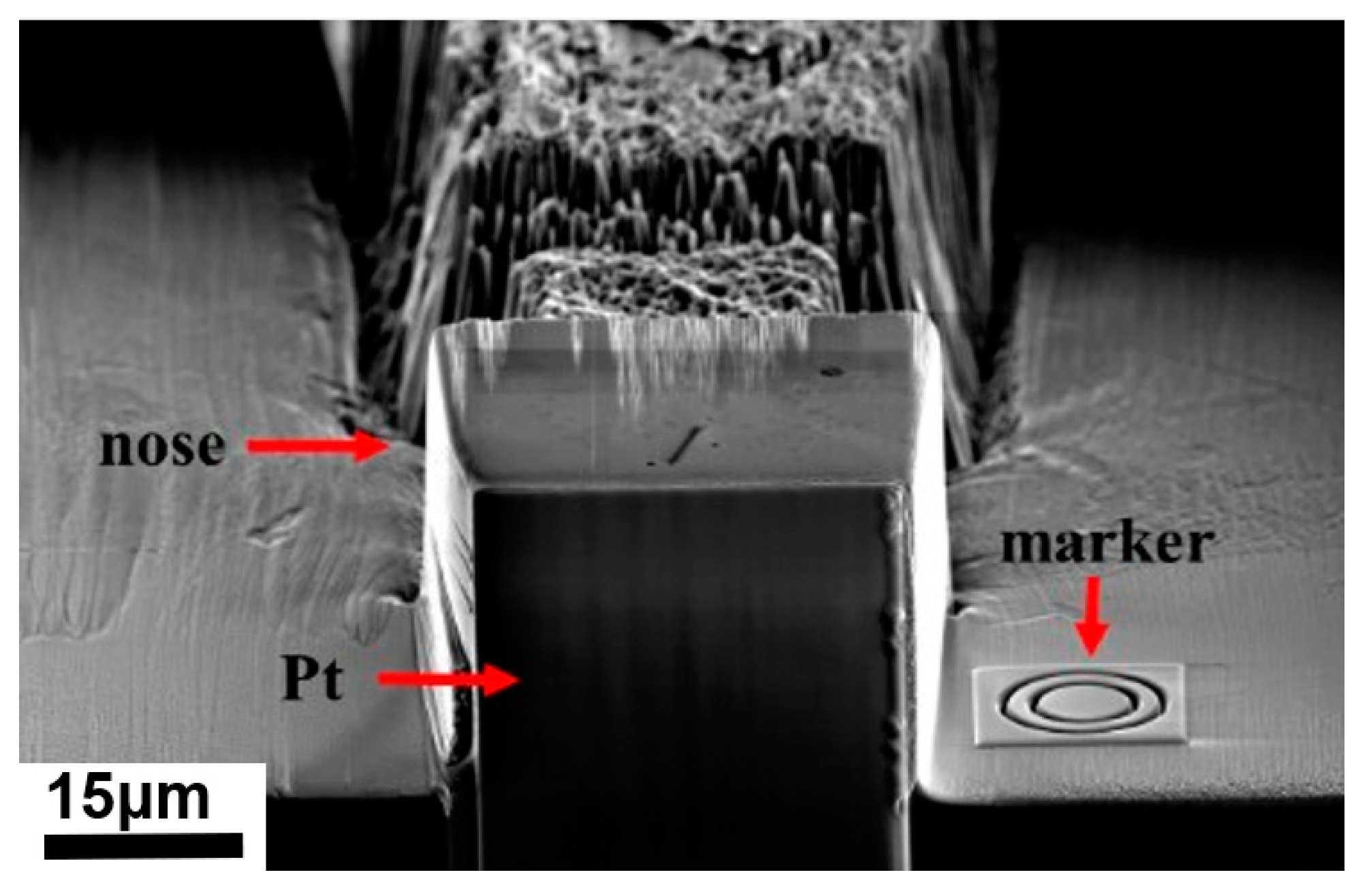
2.1. FIB Sample Preparation

EH40steel specimens were prepared for the FIB/SEM test. The chemical composition of this steel is listed in Table 1. The steel sample was austenitized at 1250 °C for 1 h and cooled to room temperature at a rate of 7 °C/s.
The sample was cut into 10 mm × 10 mm × 2 mm pieces and mechanically polished. Finally, the specimens were metallographically polished using an Ar-ion polisher to remove the surface stress.

2.2. Experimentation

FEI Scios double-beam electron microscopy (FEI Inc., Hillsboro, OR, USA) was used for the 3D reconstruction, which operates for cutting with a Ga+ beam. First, a protective layer of Pt was deposited on the specific area in order to protect the surface of the sample during the cutting process. Then the sample was cut at the tip of the nose, followed by cutting. The 2D images were aligned digitally as described elsewhere using cross-correlation of reference markers [21]. An ion beam continuously cut the sample according to the parameters set in advance. The electron beam completed the analysis of each layer. The complete 2D image and 2D electron backscatter diffraction (EBSD) information was obtained through each step of cutting and analysis. Finally, a large set of 2D images was restored in situ with Avizo software to construct a 3D morphology and crystal structure information. The method of 3D reconstruction is shown in Figure 2.
In this experiment, the cutting area was 40 × 40 μm2, the layer spacing was 150 nm, and 200 layers with a total depth of 30 μm were used.

3. Results and Discussion

The morphology, size, growth position, and crystal orientation of the Widmanstätten sideplates changed during the process of ion-beam cutting.

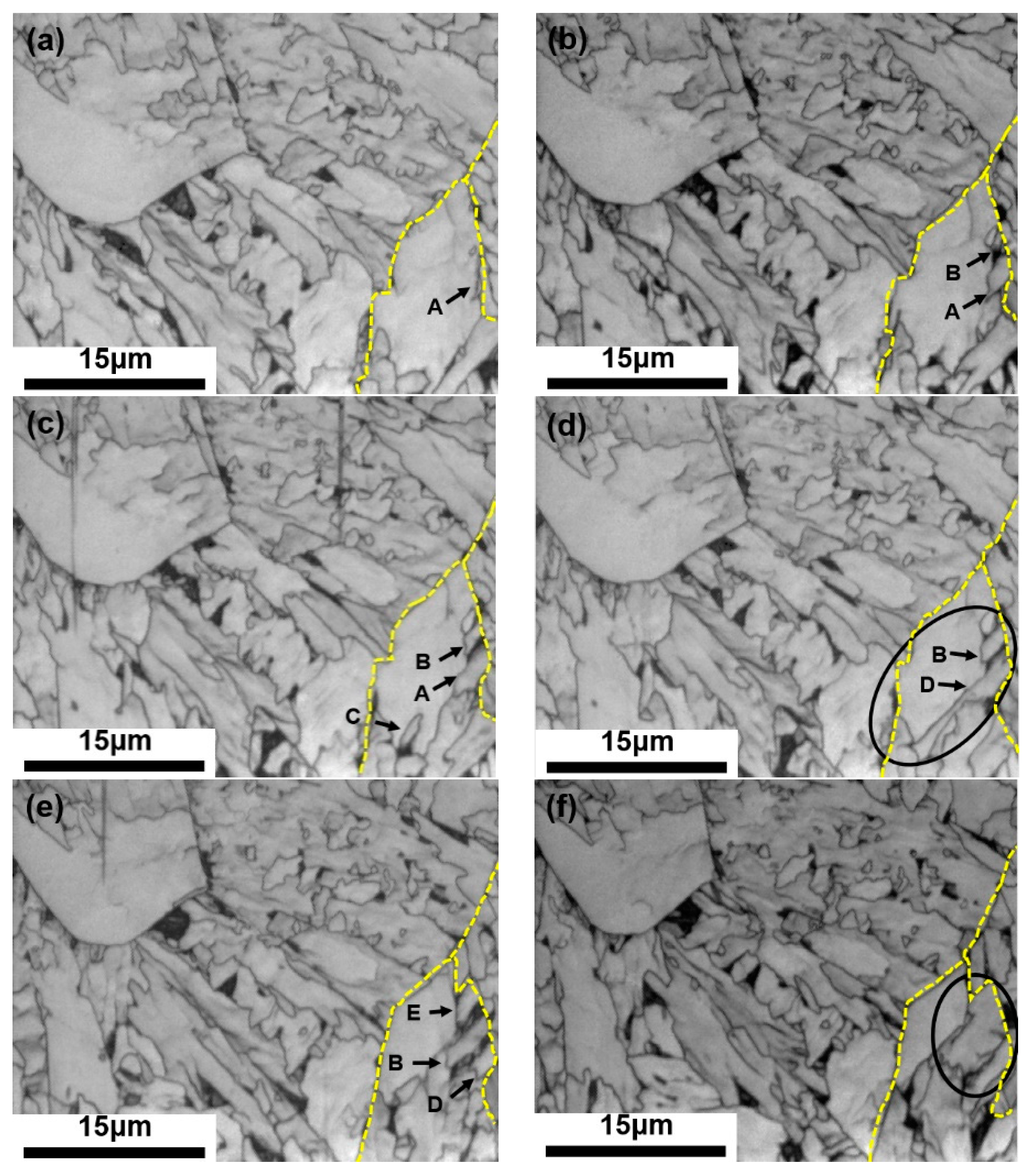
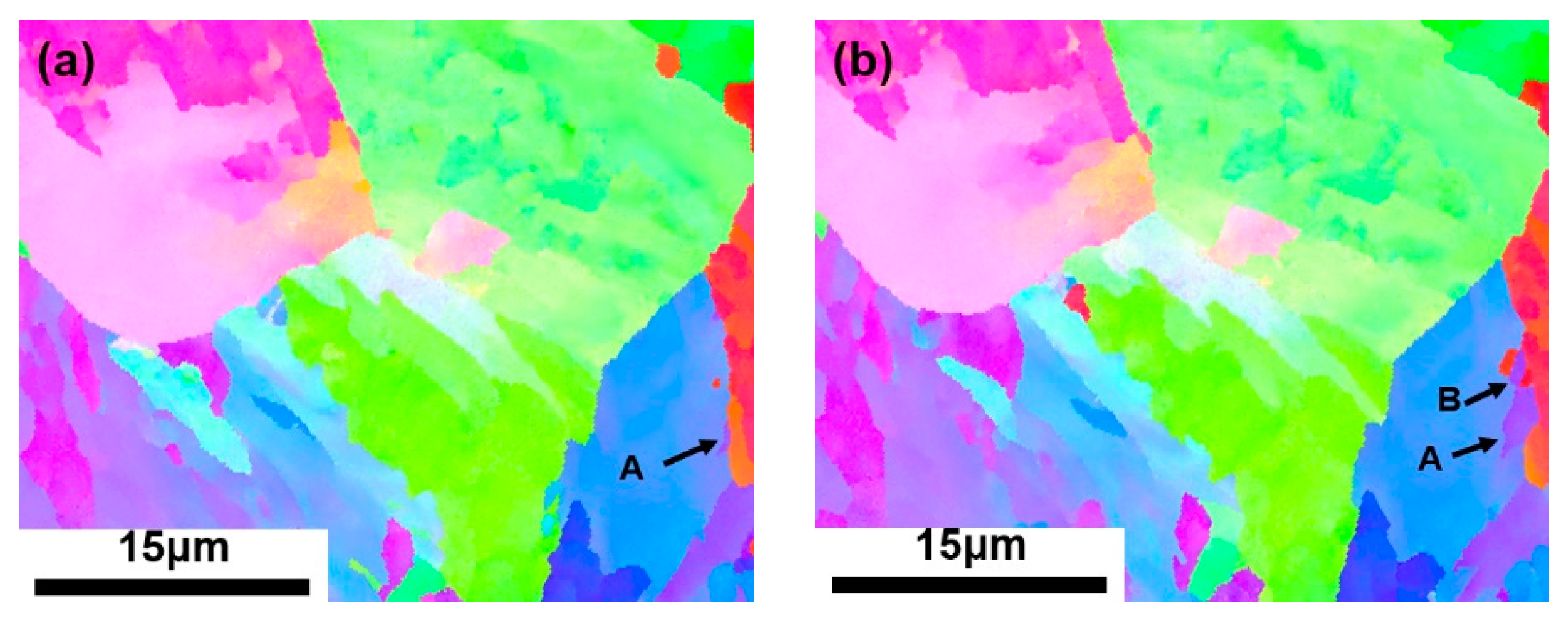
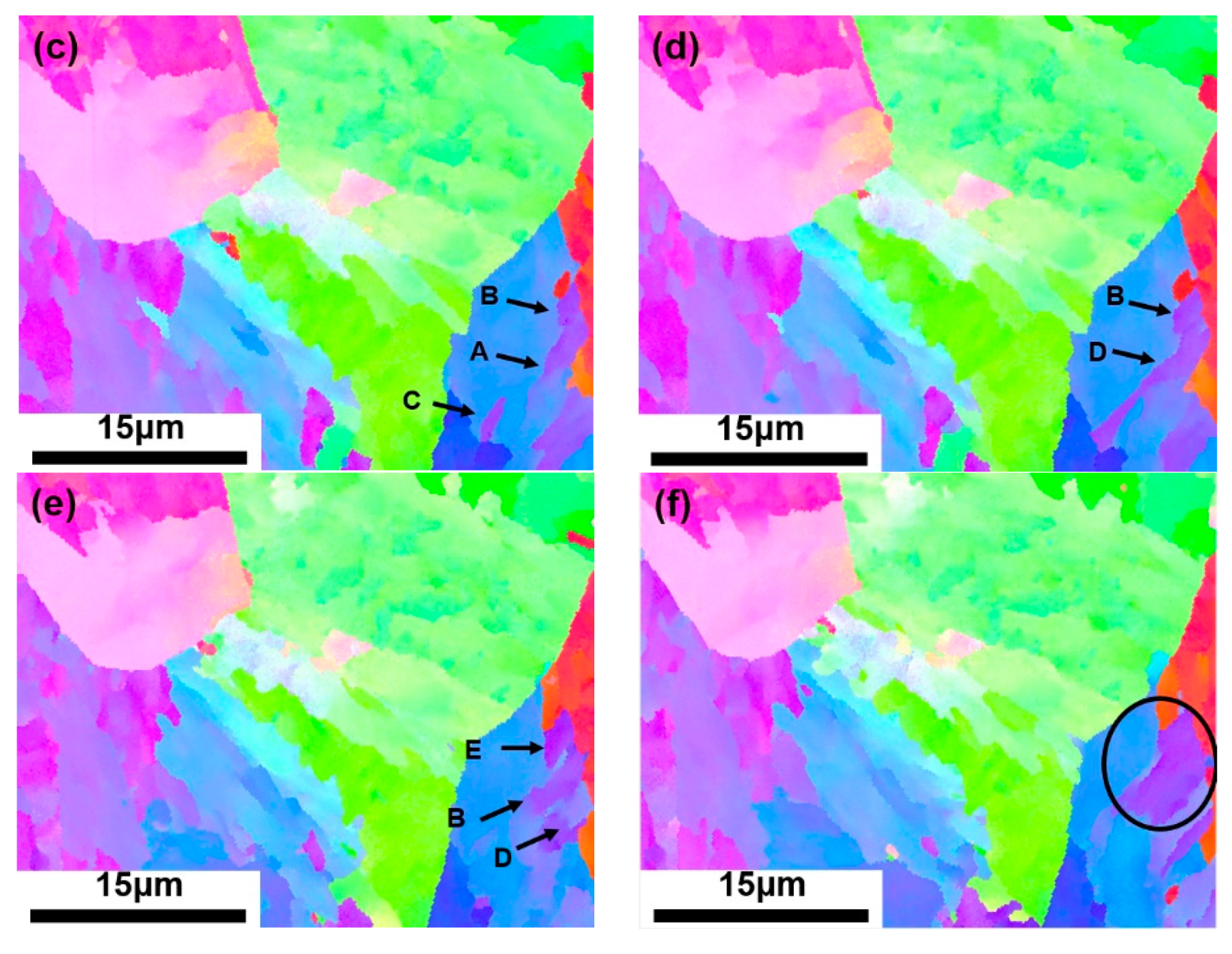
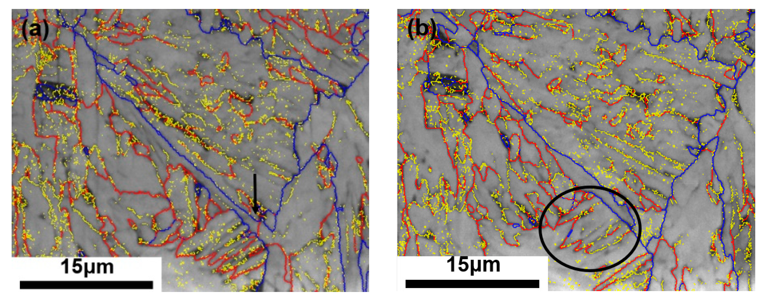
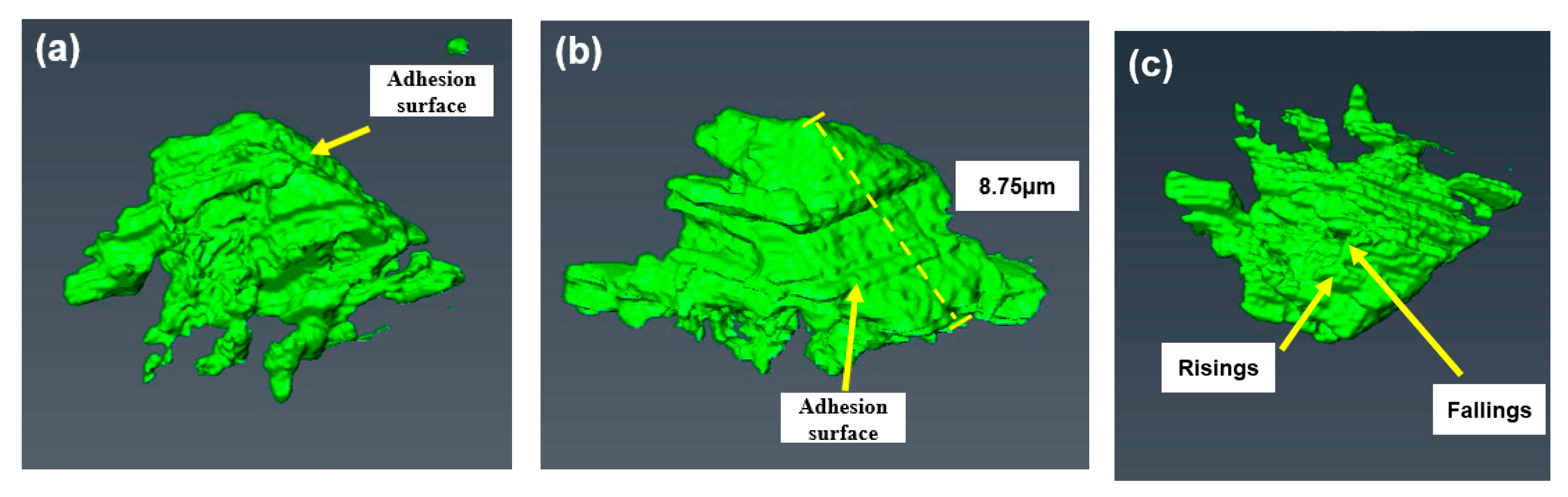
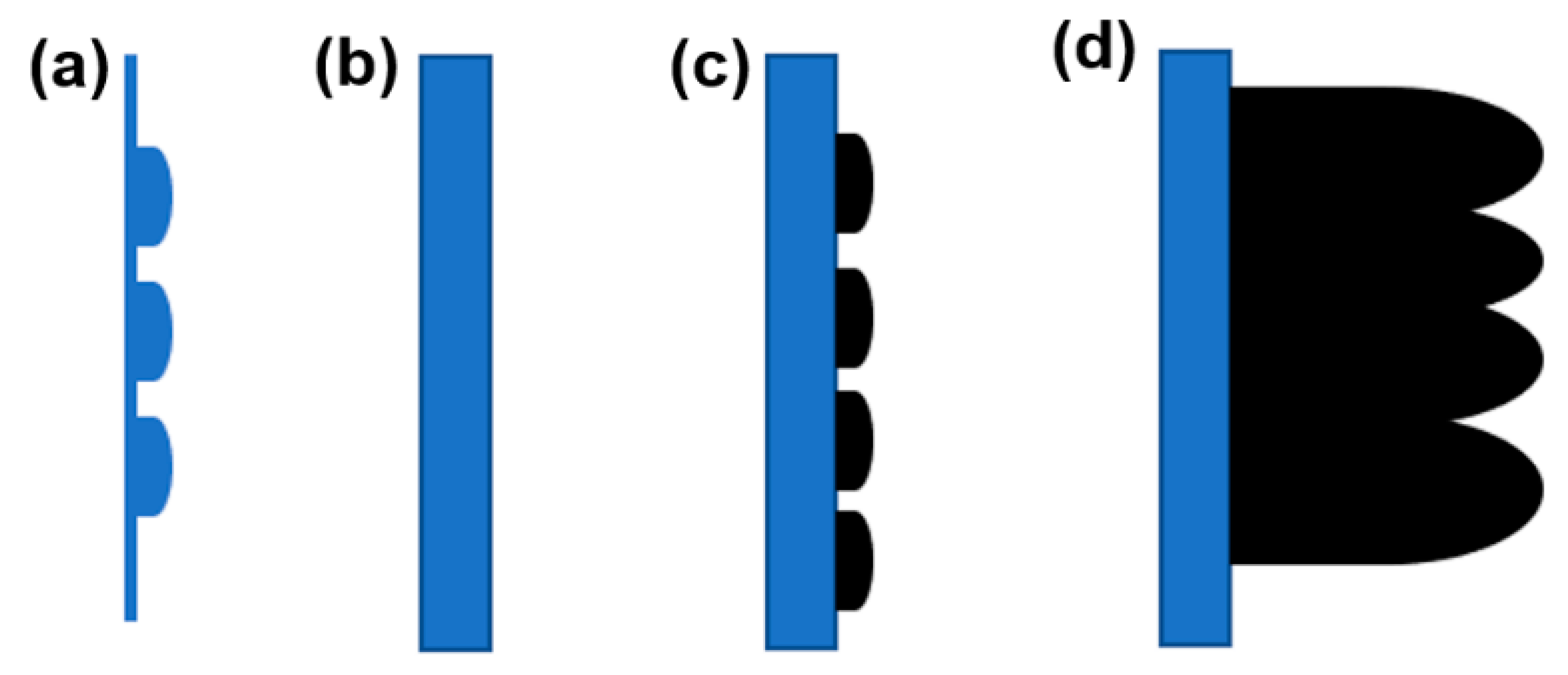
3.1. Primary Widmanstätten Sideplates

Figure 3 illustrates the 2D morphology of the primary Widmanstätten sideplates during the continuous cutting process. The dotted yellow lines represent the austenite GBs. An irregularly shaped grain A exists near the boundaries (Figure 3a). As the cutting progressed, grain A was gradually revealed, and a new grain B emerged, with both ends connected to the austenite GB (Figure 3b). A small grain C appeared in front of grain A (Figure 3c). As the cutting process progressed, grain A merged with grain C to form a large grain D (Figure 3d). Subsequently, a new grain E was observed. Grains B, D, and E were parallel to one another and grew into the grain at a certain angle with austenite GBs (Figure 3e). Subsequently, all the grains merged into a large block (Figure 3f) and gradually disappeared.
The grain orientations corresponding to Figure 3 are depicted in Figure 4. The orientations of both grains A and B were {111} (Figure 4a,b). The orientation of grain C in front of grain A was also {111} (Figure 4c). Finally, grain A and C fused to form grain D with grain orientation {111} (Figure 4d). As cutting progressed, grain E with orientation {111} was gradually exposed (Figure 4e). Finally, all the grains fused into a large block grain (Figure 4f). During the entire process, the grain orientation remained consistent at {111}.
Figure 5 illustrates the GB orientations of the 119th and 127th layers during the continuous cutting process. Among grains B, D, and E, the austenite GBs were separated by large-angle GBs (blue θ > 15°). However, small-angle GBs were separated among grains B, D, and E (yellow 2° < θ < 5°, red 5° < θ < 15°). Grains B, D, and E were separated from the other grains by small-angle GBs (red 5° < θ < 15°).
Figure 6 illustrates the 3D morphology of the reconstructed primary Widmanstätten sideplates from different perspectives. From the X–Y perspective, the morphology of the primary sideplates was “∃” shape, with long a sideplate in the middle and pits on the surface. The contact side of the GB between the primary Widmanstätten sideplates and the austenite is defined as the adhesion surface. The sideplates and the attachment side were not perpendicular but grew parallel to each other at a certain inclination angle. Holes were found in the sideplate from the X–Z perspective. From the Y–Z perspective, the adhesion surface was smooth, flat, and wide, revealing it as the contact side of the austenite GB.
The length of the adhesion surface of the primary Widmanstätten sideplates was measured and found to be 6.75 µm (Figure 6b). However, the height perpendicular to the observation direction was calculated to be 6.15 µm according to the interval and number of layers. The primary Widmanstätten sideplates first appeared in the 109th layer and finally disappeared in the 140th layer. The adhesion surface is not parallel to the observation direction but inclined. According to the inverse cosine function of the triangle, cos−1θ = 6.15/6.75, and the angle included between is θ = 24.34°.
Figure 7 illustrates the growth model of the primary Widmanstätten sideplates. During the cooling process, a few scattered ferrite grains nucleated at the GB, and then the grains fused into clusters. The newly generated ferrite preferentially developed in the form of flakes through the coherent interface at specific crystal planes and crystal directions of the austenite parent phase, such that the Widmanstätten sideplates at the tip retained their original long strip [26]. The sideplates were parallel to each other and grew into the grain at a certain angle with the austenite GBs.
The surface of the primary Widmanstätten sideplates had several pits and holes (Figure 6a,b) which may have been caused by the growth of the sideplates as they were cooled. At a temperature less than a certain value, intralagellar ferrite formed inside the grain. As the sideplates grew, the intralagellar ferrite in the grain was compressed, which hindered the continued growth of this part, and consequently forming pits and holes.
The heterogeneous nucleation of GB ferrite generally occurs near and along the austenite GB. In contrast, Widmanstätten ferrite does not grow along the GBs but along certain specific conventions of the austenite parent phase. The primary Widmanstätten sideplates directly nucleate and grow on the austenite GB and generally possess a wide base. Cheng Lin [11] ascribed this phenomenon to the rapid diffusion of carbon along or near the GB. Figure 6 shows a wide adhesion surface and a consistently sharp front.

3.2. Secondary Widmanstätten Sideplates

Figure 8 depicts the 2D morphology of the secondary Widmanstätten sideplates during the continuous cutting process. Irregularly shaped grains are observed near the GBs in Figure 8a. As the cutting progressed, the grain grew into several parallel sideplates (Figure 8b), and the GB ferrite precipitated along the tail GBs, as indicated by the yellow dotted lines. As the cutting progressed, the GB ferrite became increasingly distinct, and the tails of the parallel secondary sideplates were closely connected to the GB ferrite (Figure 8c–e). The sideplates gradually disappeared (Figure 8f).
The grain orientations corresponding to those in Figure 8 are depicted in Figure 9. Figure 9a reveals grains with an orientation of {111}. During the cutting process, the grains developed into several parallel grains at an orientation of {111}, and the tails of some grains propagated deep into the GB ferrite at an orientation between {111} and {101} (indicated by the red arrows in Figure 9b–d). The secondary Widmanstätten sideplates may be nucleated on the ferrite GB. These sideplates were firmly rooted in the GB ferrite (Figure 9e) and gradually disappeared (Figure 9f).
Figure 10 illustrates the accumulated misorientation of the red line from bottom to top of the line in Figure 9e. There is an abrupt change in orientation of 2°–3° near the interface between the bottom of the secondary Widmanstätten sideplates and the GB ferrite. Cheng Lin et al. [14] claimed that this difference was the direct evidence of nucleation excitation of the secondary Widmanstätten sideplates on GB ferrite.
The GB orientations of the 62nd and 72nd layers in the continuous cutting process are depicted in Figure 11. The ferrite contains a red small-angle GB (5° < θ < 15°) (indicated by the black arrow in Figure 11a). The grain orientations on both sides were different (Figure 9c). However, this difference in orientation disappeared in subsequent observations, which indicates a possible fusion phenomenon between the two parts during the growth of this part. The GB ferrite and secondary Widmanstätten sideplates were separated by a large-angle GB (blue θ > 15°). However, the secondary sideplates were separated by a small-angle GB (yellow 2° < θ < 5°). These sideplates were separated from other grains by small-angle GBs (red 5° < θ < 15°).
Figure 12 illustrates the reconstructed 3D morphology of the secondary Widmanstätten sideplates. From the X–Y perspective, the shape is like that of a comb. The interface between the secondary sideplates and the GB ferrite is defined as the adhesion surface. This surface is wide, and the sideplates at the front of it are not entirely parallel. From the X–Z perspective, the adhesion surface is smooth and flat. From the Y–Z perspective, the surface contains several risings and fallings, which makes it uneven.
The length of the adhesion surface of the secondary Widmanstätten sideplates was 8.75 µm (Figure 12b). However, the height perpendicular to the observation direction was 7.05 µm according to the interval and number of layers, which first appeared on the 51st layer and then disappeared on the 98th layer. The adhesion surface is not parallel to the observation direction. According to the inverse cosine function of the triangle, cos−1θ = 7.05/8.75, and the angle included between is θ = 36.32°.
Figure 13 depicts the growth model of the secondary Widmanstätten sideplates. During the cooling process, several dispersed GB ferrite grains were first formed at the GB, and gradually grew and fused to form a larger GB ferrite. Subsequently, the initial secondary Widmanstätten sideplate grains nucleated on the GB ferrite surface. The grains were parallel to one another, with one end fixed on the GB ferrite surface and the other growing inward to form ferrite sideplates. The ferrite sideplates were approximately vertical to the GB ferrite, the contact side of the GB ferrite was wide and smooth, and the front end remained sharp. Subsequently, during the continuous growth process, the intralagellar ferrite at the front end of the ferrite sideplates is obstructed, thus changing the direction and forming risings and fallings on the surface.
The secondary Widmanstätten sideplates also have a broad base and a sharp front end, which may have been caused by the nucleation of the sideplates on the GB ferrite. The sideplates possess an interface for the rapid diffusion of carbon nearby; however, limited diffusion occurs at the front end.
In this study, the secondary Widmanstätten sideplates tended to nucleate on the broad plane of the proeutectoid ferrite, which is approximately vertical to the GB ferrite and demonstrates a face-to-face excitation nucleation characteristic. During the growth process, the ferrite sideplates are parallel to one another, but the orientation is continuously tuned. From those, the secondary Widmanstätten sideplates and GB ferrite may be related by orientation. King and Bell [27] claimed that the orientation difference between the habitual plane of Widmanstätten sideplates and the GB ferrite {111} was within 0–5°. Concurring with that claim, Figure 8 highlights a surge in the 2–3° orientation difference near the nucleation interface, which is consistent with the experimental results (Figure 10).

4. Conclusions

In this study, the 3D morphology and crystal structure of Widmanstätten sideplate ferrites were analyzed using FIB/SEM equipped with EBSD. The main conclusions can be drawn as follows:
(1) Compared with the previous “quantitative continuous method”, this method can more accurately control and reduce the slice thickness of 150 nm between each layer, thereby increasing the precision and accuracy of the obtained 3D morphology
(2) Compared with the previous “quantitative continuous method”, this method not only can obtain the 3D morphology, but also the crystal structure information. Sideplates are separated by a small-angle GBs and separated from other grains by large angle GBs.
(3) The primary Widmanstätten sideplates directly nucleate and grow at the austenite GBs. The sideplates and austenite GB are inclined at a certain angle; the sideplates are approximately parallel to one another, grow inward. The shape of its 3D morphology is like “∃”, and the sideplate in the middle is long.
(4) The secondary Widmanstätten sideplates nucleate and grow on the surface of the proeutectoid GB ferrite. The sideplates and GB ferrite are perpendicular to each other. The sideplates almost parallel to each other and grow inward. The 3D morphology has a “comb” shape.
(5) The contact side of the Widmanstätten sideplates is smooth and flat and the sideplates have many defects. Pits and holes were observed on the surfaces of the sideplates of primary Widmanstätten sideplates. The sideplates’ surface of secondary Widmanstätten sideplates is rough.

Author Contributions

S.C. conducted the research and analyzed the results under the supervision of C.Z. Q.Z. contributed to the design of experiments and morphology analysis during the research activities. S.W. contributed to the image processing and data calculation. All authors have read and agreed to the published version of the manuscript.

Funding

This work was supported by the key projects of NSFC Regional Innovation and Development Joint Fund (Grant no. U21A20114), the National Natural Science Foundation of China (Grant nos. 51974130, 5217042024, and 51874137), and the Natural Science Foundation—Steel and Iron Foundation of Hebei Province (Grant no. E2020209044).

Data Availability Statement

Not applicable.

Acknowledgments

We would like to thank the Technology of Hebei Engineering Research Center of High Quality Steel Continuous Casting.

Conflicts of Interest

The authors declare no conflict of interest.

References

  1. Komine, S.; Sekido, K.; Inoue, J. In-situ measurement of surface relief induced by Widmanstätten and bainitic ferrites in low carbon steel by digital holographic microscopy. Scr. Mater. 2019, 162, 241–245. [Google Scholar] [CrossRef]
  2. Jonas, J.J.; He, Y.; Langelaan, G. The rotation axes and angles involved in the formation of self-accommodating plates of Widmanstätten ferrite. Acta Mater. 2014, 72, 13–21. [Google Scholar] [CrossRef]
  3. Lin, C.; Wan, J.; Ruan, H. Phase field modeling of Widmanstätten ferrite formation in steel. J. Alloys Compd. 2018, 769, 620–630. [Google Scholar] [CrossRef]
  4. Hillert, M.; Höglund, L.; Ågren, J. Diffusion-controlled lengthening of Widmanstätten plates. Acta Mater. 2003, 51, 2089–2095. [Google Scholar] [CrossRef]
  5. Guofang, Q.; Zhanli, D.; Yan, F. Cooling control optimization of widmanstatten structure and mixed crystal structure elimination of swrch35k hot rolled wire rod. Henan Metall. 2020, 28, 14–16. [Google Scholar]
  6. Kral, M.V.; Spanos, G. Three-dimensional analysis of proeutectoid cementite precipitates. Acta Mater. 1999, 47, 711–724. [Google Scholar] [CrossRef]
  7. Dube, C.A.; Aaronson, H.I.; Mehl, R.F. La formation de la ferrite proeutectoide dans les aciers au carbone. Rev. De Métallurgie 1958, 55, 201–210. [Google Scholar] [CrossRef]
  8. Aaronson, H.I. The Mechanism of Phase Transformation in Metals; Institute of Metals Monograph and Reports Series No.18; The Institute Of Metals: London, UK, 1956. [Google Scholar]
  9. Kaiming, W.U. Three-dimensional morphology and analysis of ferrite in steels. Chin. J. Stereol. Image Anal. 2017, 22, 119–126. [Google Scholar]
  10. Spanos, G.; Wilson, A.W.; Kral, M.V. New insights into the widmanstätten proeutectoid ferrite transformation: Integration of crystallographic and three-dimensional morphological observations. Metall. Mater. Trans. A 2005, 36, 1209–1218. [Google Scholar] [CrossRef]
  11. Kral, M.V.; Spanos, G. Three dimensional morphology of cementite precipitates. Scr. Mater. 1997, 36, 875–882. [Google Scholar] [CrossRef]
  12. Kral, M.V.; Spanos, G. Three-dimensional analysis and classification of grain boundary-nucleated proeutectoid ferrite precipitate. Metall. Mater. Trans. A 2005, 36, 1199–1207. [Google Scholar] [CrossRef]
  13. Cheng, L.; Wan, X.L.; Wu, K.M. Three-dimensional morphology of grain boundary Widmanstätten ferrite in a low carbon low alloy steel. Mater. Charact. 2010, 61, 192–197. [Google Scholar] [CrossRef]
  14. Cheng, L. The Nucleation, Three-Dimensional Morphology and Growth Kinetics in Low Carbon High Strength Micro-Alloyed steel. Ph.D. Thesis, Wuhan University of Science and Technology, Wuhan, China, 2013. [Google Scholar]
  15. Cheng, L.; Wu, K.M. New insight into intragranular ferrite in a low-carbon low-alloy steel. Acta Mater. 2009, 57, 3754–3762. [Google Scholar] [CrossRef]
  16. Hackenberg, R.E.; Nordstrom, D.P.; Shiflet, G.J. Morphology and three-dimensional structure of ferrite formed below the bay in an Fe–C–W alloy. Scr. Mater. 2002, 47, 357–361. [Google Scholar] [CrossRef]
  17. Jia, X.Z.; Wang, Y.; Xing, Y.; Liu, Q.; Liu, F.I.B. Three-dimensional characterization analysis techniques and its application progress. Mater. China 2013, 32, 735–741. [Google Scholar]
  18. Inkon, B.J.; Mulvihill, M.; Mobus, G. 3D determination of grain shape in a FeAl-based nanocomposite by 3D FIB tomography. Scr. Mater. 2001, 45, 753–758. [Google Scholar] [CrossRef]
  19. Villinger, C.; Gregorius, H.; Kranz, C.; Höhn, K.; Münzberg, C.; von Wichert, G.; Walther, P. FIB/SEM tomography with TEM-like resolution for 3D imaging of high-pressure frozen cell. Histochem. Cell Biol. 2012, 138, 549–556. [Google Scholar] [CrossRef]
  20. Uchic, M.D.; Groeber, M.A.; Dimiduk, D.M.; Simmons, J.P. 3D micro structural characterization of nickel superalloys via serial-sectioning using a dual beam FIB-SEM. Scr. Mater. 2006, 55, 23–28. [Google Scholar] [CrossRef]
  21. Cao, S.; Tirry, W.; Van Broek, D.; Schryvers, D. Optimization of a FIB/SEM slice-and-view study of the 3D distribution of Ni4Ti3 precipitates in Ni–Ti. J. Microsc. 2009, 233, 61–68. [Google Scholar] [CrossRef]
  22. Zankel, A.; Wagner, J.; Peter, P. Serial sectioning methods for 3D investigations in materials science. Micron 2014, 62, 66–78. [Google Scholar] [CrossRef]
  23. Groeber, M.A.; Haley, B.K.; Uchic, M.D. 3D reconstruction and characterization of polycrystalline microstructures using a FIB-SEM system. Mater. Charact. 2006, 57, 259–273. [Google Scholar] [CrossRef]
  24. Mingard, K.P.; Jones, H.G.; Gee, M.G. Metrological challenges for reconstruction of 3-D microstructures by focused ion beam tomography methods. J. Microsc. 2014, 253, 93–108. [Google Scholar] [CrossRef] [PubMed] [Green Version]
  25. Fan, G.H.; Zhang, Y.B.; Driver, J.H.; Jensen, D.J. Oriented growth during recrystallization revisited in three dimensions. Scr. Mater. 2014, 72/73, 9–12. [Google Scholar] [CrossRef]
  26. Wu, S.; Zhang, C.; Zhu, L.; Zhang, Q.; Ma, X. In-depth analysis of intragranular acicular ferrite three-dimensional morphology. Scr. Mater. 2020, 185, 61–65. [Google Scholar] [CrossRef]
  27. King, A.D.; Bell, T. Morphology and crystallography of Widmanstätten proeutecoid ferrite. Met. Sci. 1974, 8, 253–260. [Google Scholar] [CrossRef]
Figure 1. Classification of Widmanstätten ferrite. (a) Primary Widmanstätten sideplates, (b) Secondary Widmanstätten sideplates, (c) Primary Widmanstätten sawteeth, (d) Secondary Widmanstätten sawteeth.
Metals 12 00523 g001
Figure 2. Schematic diagram of cutting sample.
Metals 12 00523 g002
Figure 3. Scanning electron microscopy (SEM) image of primary Widmanstätten sideplates cutting process. (a) 110th layer, (b) 114th layer, (c) 117th layer, (d) 119th layer, (e) 127th layer, (f) 131st layer.
Metals 12 00523 g003
Figure 4. Grain orientation of primary Widmanstätten sideplates cutting process. (a) 110th layer, (b) 114th layer, (c) 117th layer, (d) 119th layer, (e) 127th layer, (f) 131st layer.
Metals 12 00523 g004aMetals 12 00523 g004b
Figure 5. GB orientation of primary Widmanstätten sideplates cutting process. (a) 119th layer, (b) 127th layer.
Metals 12 00523 g005
Figure 6. 3D morphology of primary Widmanstätten sideplates from different perspectives. (a) X–Y, (b) X–Z, (c) Y–Z.
Metals 12 00523 g006
Figure 7. Primary Widmanstätten sideplate growth. (a) Nucleation, (b) growth.
Metals 12 00523 g007
Figure 8. 2D SEM image of the secondary Widmanstätten sideplate cutting process. (a) 51st layer, (b) 59th layer, (c) 62nd layer, (d) 68th layer, (e) 72nd layer, (f) 93rd layer.
Metals 12 00523 g008
Figure 9. Grain orientation of secondary Widmanstätten cutting process. (a) 51st layer, (b) 59th layer, (c) 62nd layer, (d) 68th layer, (e) 72nd layer, (f) 93rd layer.
Metals 12 00523 g009
Figure 10. Accumulated misorientation of red line in Figure 9e.
Metals 12 00523 g010
Figure 11. GB orientation of secondary Widmanstätten sideplates cutting process. (a) 62nd layer, (b) 72nd layer.
Metals 12 00523 g011
Figure 12. 3D morphology of secondary Widmanstätten sideplates from different perspectives. (a) X–Y, (b) X–Z, (c) Y–Z.
Metals 12 00523 g012
Figure 13. Diagram of secondary Widmanstätten sideplates growth. (a) GB ferrite nucleates at GBs, (b) Larger GB ferrite is formed, (c) Secondary Widmanstätten sideplates nucleate at grain boundary ferrite, (d) Secondary Widmanstätten sideplates growth.
Metals 12 00523 g013
Table 1. Chemical composition of high-strength low-alloy steels (mass, %).
IngredientCSiMnPSAlMoCuNiVNbTiCr
Composition0.070.281.620.010.0040.040.070.0080.0040.0050.020.0170.02
Publisher’s Note: MDPI stays neutral with regard to jurisdictional claims in published maps and institutional affiliations.

