Article

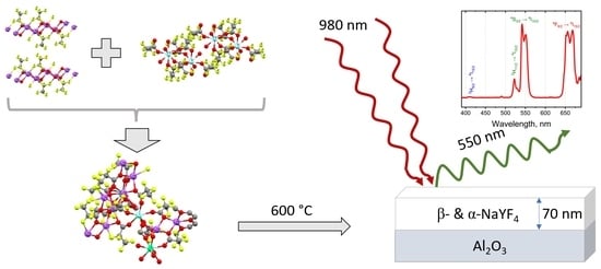
Single-Source Precursors for Chemical Solution Deposition of Up-Converting NaLnF4 Thin Films

by
Artem Shevchenko
1,2,
Andrei Anosov
1,2,
Daria Blinnikova
1,2,
Dimitry Grebenyuk
1,3 and
Dmitry Tsymbarenko
1,*
1
Department of Chemistry, Lomonosov Moscow State University, 119991 Moscow, Russia
2
Faculty of Materials Science, Lomonosov Moscow State University, 119991 Moscow, Russia
3
Faculty of Materials Science, MSU-BIT University, Shenzhen 518172, China
*
Author to whom correspondence should be addressed.
Metals 2022, 12(3), 488; https://doi.org/10.3390/met12030488
Submission received: 9 February 2022 / Revised: 6 March 2022 / Accepted: 11 March 2022 / Published: 14 March 2022

Abstract

:
Novel single-source precursors based on sodium and lanthanide pentafluoropropionates have been developed for chemical solution deposition of NaLnF4 thin films (Ln = Y, Yb, Er, Tm). A series of [Ln2(pfp)6Qn] (Q = H2O, diglyme) and mixed-metal NaLn(pfp)4Qn were synthesized and characterized by X-ray diffraction (XRD) and thermogravimetric analysis (TG-DTA). Thermal decomposition of individual Na(pfp) and Ln(pfp)3 occurs at different temperatures while single-source NaLn(pfp)4 decomposes with the transformation to NaLnF4 in a single stage at 280 °C. Further crystallization of NaLnF4 was studied by variable-temperature powder XRD, which shows two phase transformations from cubic NaLnF4 to hexagonal NaLnF4 at 310 °C and back to a high-temperature cubic phase at 560 °C. The thin films of NaY0.78Yb0.2Er0.02F4 prepared by the dip-coating technique on Al2O3 substrates showed intense up-converting luminescence in green and blue regions under 980 nm excitation.

Graphical Abstract

1. Introduction

Sodium rare-earth fluorides have received much attention in the past decades, especially in the form of nanocrystals, because of their unique features: charge transfer and up-conversion luminescence (UCL) [1,2,3,4]. It is well known that NaYF4 exists in cubic (α, fluorite type) or hexagonal (β, gagarinite type) modifications, and hexagonal β-NaYF4 is considered to be the most effective host matrix for the Yb3+-Er3+ system, where the roles of the doping ions are sensibilization and activation, respectively [4,5]. Due to the exceptional chemical and thermal stability of metal fluorides, the formation of their thin films turns out to be a very challenging objective, requiring either high vacuum techniques [6,7] or a tricky electrochemical approach [8,9]. On the one hand, the corrosive effect of both elemental fluorine and fluoride ions makes already expensive physical vapor deposition techniques even more expensive by accelerated degradation of vacuum pumps, which renders the approach unpreferable. On the other hand, the electrochemically deposited fluoride films consist of 100% cubic NaYF4 phase, which is a bad choice for optical applications. Chemical vapor deposition from metal organic precursors (MOCVD) is a robust method for smooth and homogeneous thin film fabrication at elevated temperatures. Recently, the concept of a third-generation single-source precursor with all necessary elements in one molecule has been proposed [10]. Volatile mixed-metal coordination compound [Na(tetraglyme)][Ln(hfa)4] (hfa is hexafluoroacetylacetonate-anion) served as a source of fluorine atoms, and was successfully applied for the preparation of single-phase α-NaYF4 thin film [10]. Another chemical method for thin film preparation is the metal-organic chemical solution deposition (MOCSD), which in contrast to MOCVD allows for the precise control of cation composition of growing thin film that is essential for multi-component up-converting NaLnF4 films, e.g., NaY0.78Yb0.20Er0.02 [4,5]. Additionally, MOCSD is a simple and easily scalable technique; however, it requires a special design of metal-organic precursors. It has been reported that thermolysis of metal perfluorinated carboxylates (trifluoroacetates, pentafluoropropionates) also led to the formation of metal fluorides [11,12], which makes them valuable precursors for NaLnF4 films and nanocrystals [13,14]. Mixed-ligand complexes, e.g., [Ln2(tfa)6(diglyme)2] [15,16] and [Ln(tfa)2(deta)2](tfa) [17], have been elaborated to modify the solubility and reactivity of precursors. Several polymeric single-source precursors for NaLnF4 nanocrystals [NaLn(TFA)4(diglyme)] [18,19], [NaY(TFA)4(diglyme)], [[Na(triglyme)2][Y2(TFA)7(THF)2]] and [Na2Y(TFA)5(tetraglyme)] [20] were also reported.
Here we present for the first time the development of a series of mono- and bimetallic precursors for MOCSD preparation of up-converting NaLnF4 thin films based on metal pentafluoropropionates and a detailed study of the phase transformation during thermal treatment.

2. Materials and Methods

2.1. Synthesis of Metal Pentafluoropropionates

Rare earth and sodium carbonates (analytical grade, Reakhim, Moscow, Russia), pentafluoropropionic acid (Hpfp, 99%, P&M Invest, Moscow, Russia), diglyme (bis(2-methoxyethyl) ether, 99%, Fluka Honeywell, Charlotte, NC, USA) and isopropanol (Irea2000, Moscow, Russia, 99%) were used as received. Acetonitrile (Irea2000, Moscow, Russia, 99%) was preliminarily dried over P2O5, distilled, and stored over 3Å molecular sieves under argon.
Na(pfp) and [Ln2(pfp)6(H2O)6] (1Ln) were prepared similarly to the reported method [17] from corresponding metal carbonate, which was placed into the glass beakers with deionized water and Hpfp with 10% excess to the stoichiometric amount was added dropwise. The mixture was stirred at room temperature until there was a complete dissolution of the carbonates and then recrystallized 3 times with the addition of extra water each time to get rid of remaining acid. Then, the solution was filtered using a PTFE Syringe filter (pore size 0.2 μm, Cole-Parmer, Vernon Hills, IL, USA) to remove the remaining particles and evaporated on a hot plate at 60 °C until complete water removal. The purity of the resulting powders was confirmed by agreement of X-ray diffraction (XRD) and thermogravimetric analysis (TG-DTA)data with the previously reported ones [11,12].
Mixed-ligand complexes [Ln2(pfp)6(diglyme)2] (2Ln) were prepared using a Schlenk line from as-obtained pentafluoropropionate hydrates. Powder of Ln(pfp)3(H2O)3 (0.56 mmol, ca. 0.4 g) was placed into a Schlenk flask and heated under vacuum at 110 °C for 40 min. After cooling to room temperature, acetonitrile (2.5 mL) and diglyme (1.12 mmol, 0.161 mL) were added to the generated Ln(pfp)3 powder under vigorous stirring in Ar atmosphere. Then, the flask was heated to 90 °C inside the Dewar vessel filled with hot water to obtain a clear solution and was left until it cooled naturally to room temperature, when crystalline precipitate was formed gradually. Yield: 70–80%.

2.2. NaLnF4 Powders Preparation and VT-PXRD Study

Sodium and rare-earth pentafluoropropionates were dissolved in isopropanol for homogenization and then the solvent was evaporated until wet gel formation. After that, the samples were placed into a quartz boat and put into the furnace, where they were annealed at the desired temperatures. Samples for variable-temperature PXRD (VT-PXRD) measurements were prepared by thermal decomposition of single-source precursor at the lowest possible temperature (240–250 °C) to obtain a poorly crystallized powder, which was then placed into corundum sample holder. The VT-PXRD experiment was performed on Rigaku SmartLab (Tokyo, Japan) using the Anton Paar HTK 1200 N chamber (Anton Paar, Graz, Austria) with a step temperature program (10 °C/step) from room temperature to 600 °C. The full-profile Rietveld refinement of the XRD pattern at each certain temperature was performed to determine the phase fraction and the sizes of the crystallites. The instrumental profile function was treated by a fundamental approach as implemented in Jana2006 software [21].

2.3. Precursor Solution Preparation and Thin Film Deposition

The precursor solution for thin film deposition was prepared by dissolving metal pentafluoropropionates in 5 mL isopropanol with the following cation ratio: Na+:Y3+:Yb3+:Er3+ = 100:78:20:2 and concentration of the rare-earth elements c(Ln) = 0.3 M. After obtaining a clear solution, 1.5 mmol of diglyme was added dropwise during stirring. Metal carboxylate films were deposited on a single-crystal c-Al2O3 substrate implying the dip-coating technique with a pulling rate of 1 mm/s and a drying temperature of Td = 135 °C. Then, the resulting amorphous precursor films were annealed at 400 and 600 °C for 15 min under argon with minor amounts of HF released from KHF2.

2.4. Methods and Instrumentation

XRD patterns were recorded on a Rigaku SmartLab diffractometer (Tokyo, Japan, 2θ = 3–80°; Cu Kα1 radiation) in θ–2θ and grazing-incidence XRD (GIXRD, grazing angle was 0.5°) geometries. TG-DTA curves were obtained on Derivatograph Q-1500 D (MOM, Budapest, Hungary) in the static air condition with a heating rate of 10 °/min using the alumina crucible without a cap; the mass of the sample was 50 mg. Atomic force microscopy (AFM) was performed using NTEGRA Aura (NT-MDT, Moscow, Russia) in semicontact mode. The thickness of the films was determined by AFM profiling of artificial scratches on the film surface. The up-conversion luminescence (UCL) spectra were measured using the setup from a 980 nm diode laser with an average pumping power of 800 mW (Besram Technology Inc., Wuhan, China) and Ocean Optics USB2000 spectrometer (Orlando, FL, USA).

2.5. X-ray Crystallography

Single-crystal X-ray diffraction data were collected at 100K on a Bruker D8 QUEST (Incoatec micro-focus Mo Kα X-ray tube, Photon III detector, Bruker AXS Inc., Madison, WI, USA) and Bruker Smart APEXII DUO (graphite monochromator, Mo Kα X-ray tube, CCD detector, Bruker AXS Inc., Madison, WI, USA). Single crystals of 1Y and 2Tm were obtained by recrystallization of acetonitrile solution, and crystals of 3Ln were collected after crystallization of precursor solution during 3 months. Absorption correction for 1Y and 2Tm crystals was performed using SADABS [22]. The crystal of 3Ln was considered a two-component non-merohedral twin, which was detwinned using the CELL_NOW tool [23] and corrected for absorption by TWINABS [24]. Crystal structures were solved by direct methods and refined anisotropically for all non-H atoms with the full-matrix F2 least-squares technique using SHELXTL PLUS [25]. H atoms of water molecules were localized from Fourier maps, other H-atoms were placed in idealized positions, and all H-atoms were refined in a riding model. Further details of the data collection and refinement are summarized in Table 1. CCDC reference number 2131909-2131911 contains the supplementary crystallographic data for this paper. These data can be obtained free of charge via http://www.ccdc.cam.ac.uk/conts/retrieving.html (accessed on 8 February 2022) (or from the CCDC, 12 Union Road, Cambridge CB2 1EZ, UK; Fax: +44 1223 336033; E-mail: [email protected]).

3. Results and Discussion

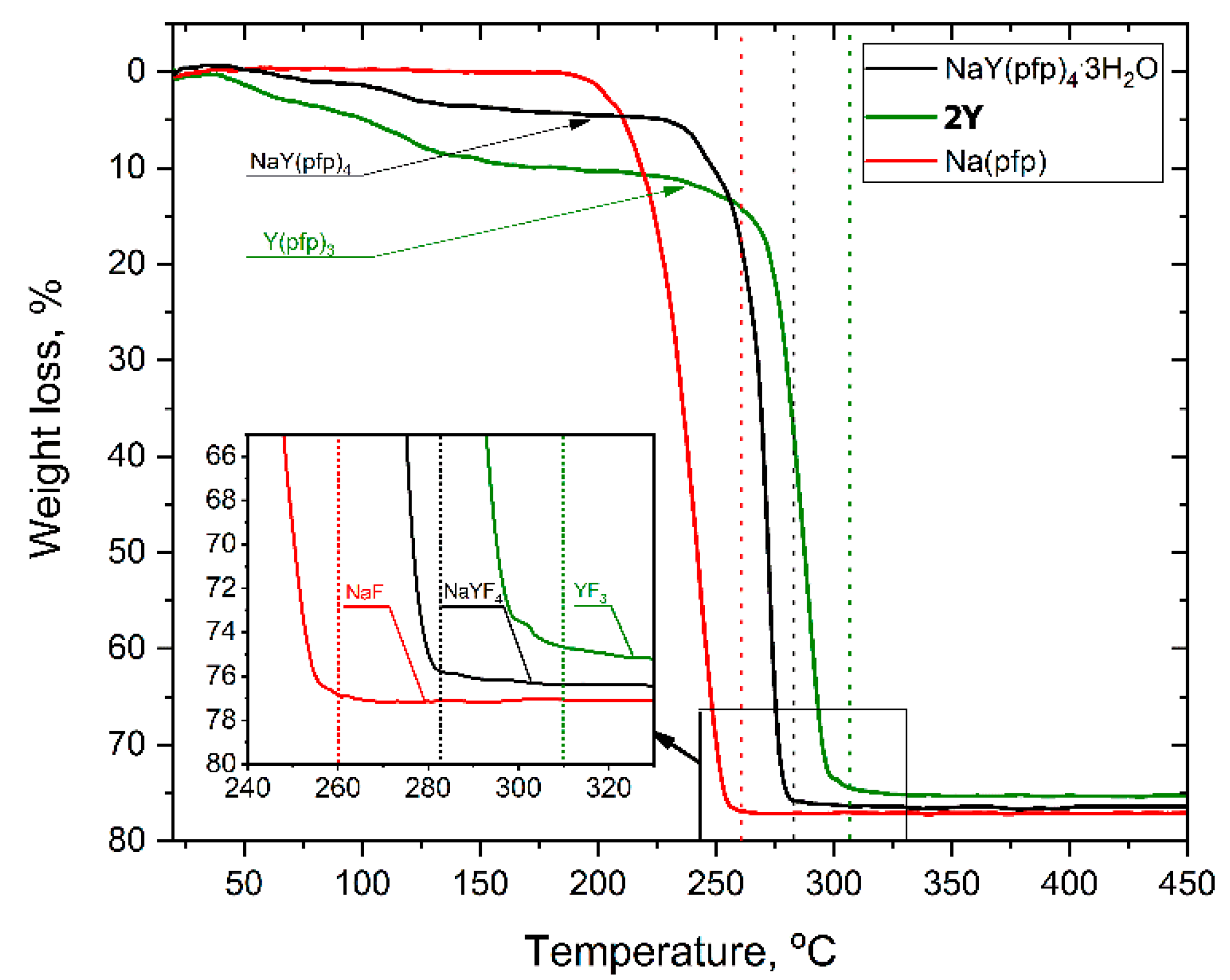
3.1. Synthesis and Thermal Behavior of Single-Source Precursors

Powders of sodium and lanthanide pentafluoropropionates isolated from water solution are well soluble in alcohols (methanol, isopropanol, etc.). Crystallization from isopropanol solutions of individual [Na(pfp)] or [Ln2(pfp)6(H2O)6] (1Ln) yields the well-crystalline powders (Figure 1) with compositions similar to as-obtained ones and with Powder XRD (PXRD) patterns being in a good agreement with the theoretical patterns calculated from the single-crystal structures of Na(pfp) [12] and [Y2(pfp)6(H2O)6] (1Y). One should note the extra peak at a small angle in experimental PXRD of 1Y that corresponds to the by-product phase, which forms tiny needle-like crystals unsuitable for X-ray structure analysis. More importantly, crystallization of a solution containing both [Na(pfp)] and 1Ln simultaneously leads to the formation of a novel bimetallic complex NaY(pfp)4(H2O)3. The unique PXRD pattern of the NaY(pfp)4(H2O)3 sample contains no peaks originating from the patterns of individual [Na(pfp)] or 1Ln phases, which confirms the formation of a single phase with an entirely new crystal structure (Figure 1).
The formation of a single-source bimetallic complex significantly affected the thermal behavior of the precursors. Indeed, the individual [Na(pfp)] or 1Ln phases totally decomposed with the formation of metal fluorides at remarkably different temperatures, 260 and 300 °C, respectively (Figure 2). This feature along with impeded diffusion at low temperatures increased the risk of formation of the final material in the form of disintegrated NaF and YF3 grains.
Thermal decomposition of NaY(pfp)4(H2O)3 occurs in two stages (Figure 2). The first preliminary stage of weight loss (70–170 °C) corresponds to the elimination of three water molecules (calc—6.6 %, found—5.4 %), resulting in an anhydrous NaY(pfp)4. The later one decomposes at the second stage in a narrow temperature range of 240–280 °C with the formation of pure NaYF4 (calc. total weight loss—77.0%, found—76.4%), which was confirmed by the PXRD of the residue. It should be noted that total decomposition temperature of NaY(pfp)4, ca. 283 °C, is close to the median value between Na(pfp) and Y(pfp)3.
The use of the elaborated compounds as single-source precursors for fluoride thin film deposition is very convenient since the cationic ratio of rare-earth elements could be easily controlled by dissolving various amounts of powder precursors, which is very important for optical and magnetic applications. Moreover, deposition from the solution provides a homogeneous distribution of elements only if there would be no place for crystallization on the substrate during the drying stage. The ability to form well-crystalline powder most probably originates from the relatively large lattice energy of Na(pfp) and 1Ln polymeric crystal structures, and from the additional framework of intermolecular hydrogen bonds in 1Ln. In order to modify the composition and structure of complexes in solution and to prevent their crystallization, the gel-stabilizer, diglyme, was added to isopropanol or acetonitrile precursor solutions. The ability of diglyme to coordinate the Ln atom as a chelating and bridging ligand and to form mixed-ligand complexes preserves such a solution from crystallization on the substrate, but at the same time, it diminishes the opportunity of structure determination of the single-source precursor [26]. However, in the anhydrous conditions of the Schlenk apparatus, the crystalline products of [Ln2(pfp)6(diglyme)2] complexes (2Ln), Ln = Y, Er, Tm, Yb, were isolated from acetonitrile solution of Ln(pfp)3 and diglyme and were found to be isostructural to a 2Tm analog whose crystal structure was determined (Figure 3). By contrast, the mixed-metal precursor solution of Na(pfp), Ln(pfp)3 and diglyme forms a very viscous clear gel without any crystalline product during solvent evaporation. Thus, the crystallization of the later one became only possible due to the partial degradation of the ligands, which resulted in the formation of poorly soluble polymeric compounds. Indeed, the storage of precursor solution based on Na, Y, Yb and Er pentafluoropropionates with diglyme after three months led to the formation of a few X-ray quality single crystals of coordination polymer [Na7Ln2(pfp)11(form)(diglyme)(Meac)] (3Ln), where form, (HCOO) and Meac (MeOC2H4OCH2COO) anions were formed due to degradation of pfp and diglyme ligands.

3.2. Crystal Structure

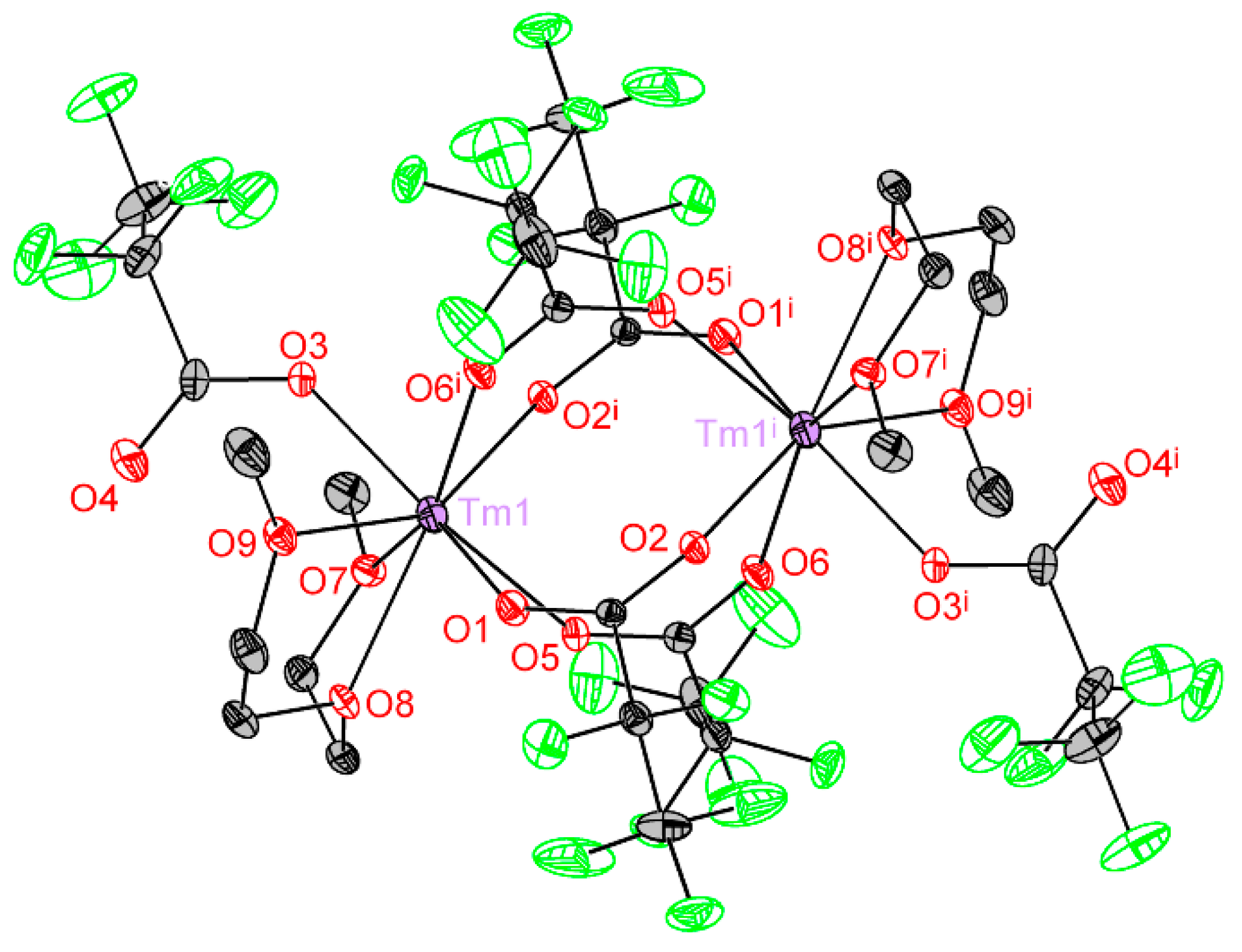
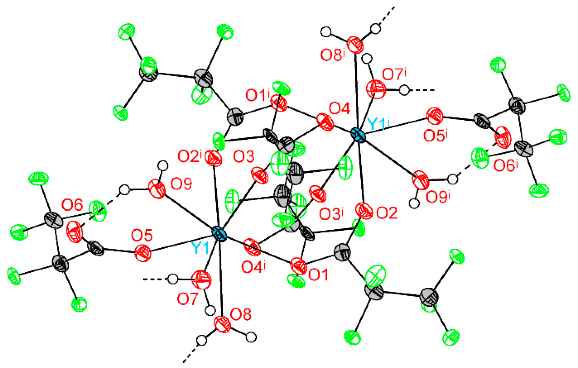
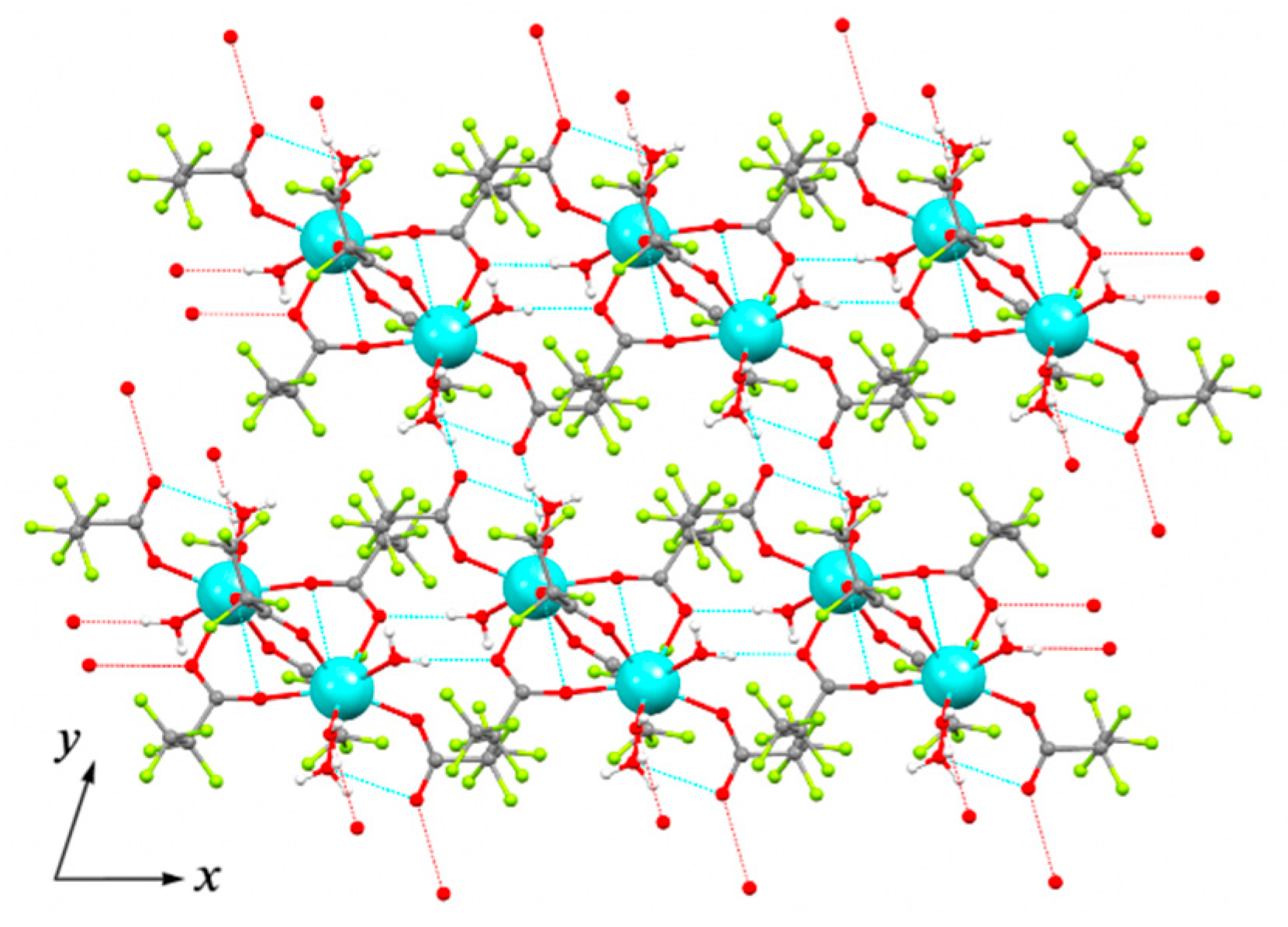
3.2.1. [Ln2(pfp)6(H2O)6] (Ln = Y, Er, Tm, Yb) (1Ln)

Crystal structure of 1Ln series was determined for Y analog (1Y) by single-crystal XRD. The triclinic unit cell contains centrosymmetric binuclear [Y2(pfp)6(H2O)6] molecules (Figure 4). The Y cation is coordinated by three O atoms from water molecules, four O atoms of four bridging pfp anions and one O atom of terminal pentafluoropropionate anion (Table 2). Thus, the coordination number (CN) of Y equals to 8 and the environment is best described as a distorted double-capped trigonal prism. The Y∙∙∙Yi distance is 4.520 Å, which is common for other binuclear complexes of rare-earth elements. Binuclear molecules of 1Y are packed parallel to each other in the ab plane (Figure 5). The framework of H-bonds defines the mutual orientation of molecules within the layer. The structure of 1Y is isotypic to previously reported Gd analog [27], while the Y-O distances are 0.04–0.06 Å shorter than Gd-O ones due to the smaller ionic radius of Y cation.

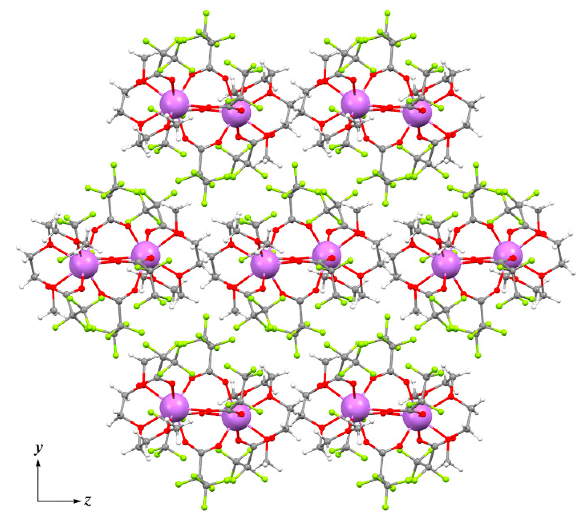
3.2.2. [Ln2(pfp)6(diglyme)2], (Ln = Y, Er, Tm, Yb) (2Ln)

Crystal structure of 2Ln series was determined for Tm analog. The monoclinic unit cell contains two symmetrically related centrosymmetric binuclear molecules of [Tm2(pfp)6(diglyme)2] (Figure 6). Tm atom with CN equal to 8 is coordinated by O1, O5, O2i and O6i atoms of four bridging pfp anions, one O3 atom of a terminal pfp anion, and O7, O8 and O9 atoms of the chelating diglyme ligand (Table 3). The coordination polyhedron of Tm is best described as a distorted double-capped trigonal prism.
Therefore, the molecular structure of 2Tm is very similar to that in the 1Y structure, where H2O molecules are replaced with three donor atoms of diglyme ligand. By contrast to 1Y, the diglyme in 2Tm prevents the formation of an H-bonds framework and results in the packing of isolated binuclear molecules in a pseudo-hexagonal motif within the bc plane (pseudo-hexagonal cell parameter γh = 121.63°, Figure 7). Comparison of 2Tm with the previously reported isotypic [Ln2(tfa)6(diglyme)2] (Ln = Gd, Tm, Yb) trifluoroacetate analog [15] reveals the interatomic distances in 2Tm to be 0.01–0.03 Å larger than in Tm2(tfa)6(diglyme)2, which is attributed to the increase in steric hindrance with bulky pfp ligands. Additionally, in contrast to 2Tm, the pseudo-hexagonal motif of Tm2(tfa)6(diglyme)2 packing cannot be recognized.

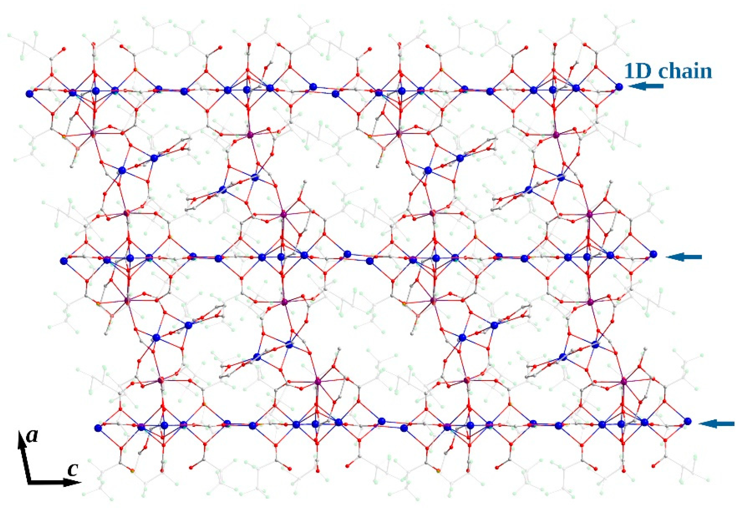
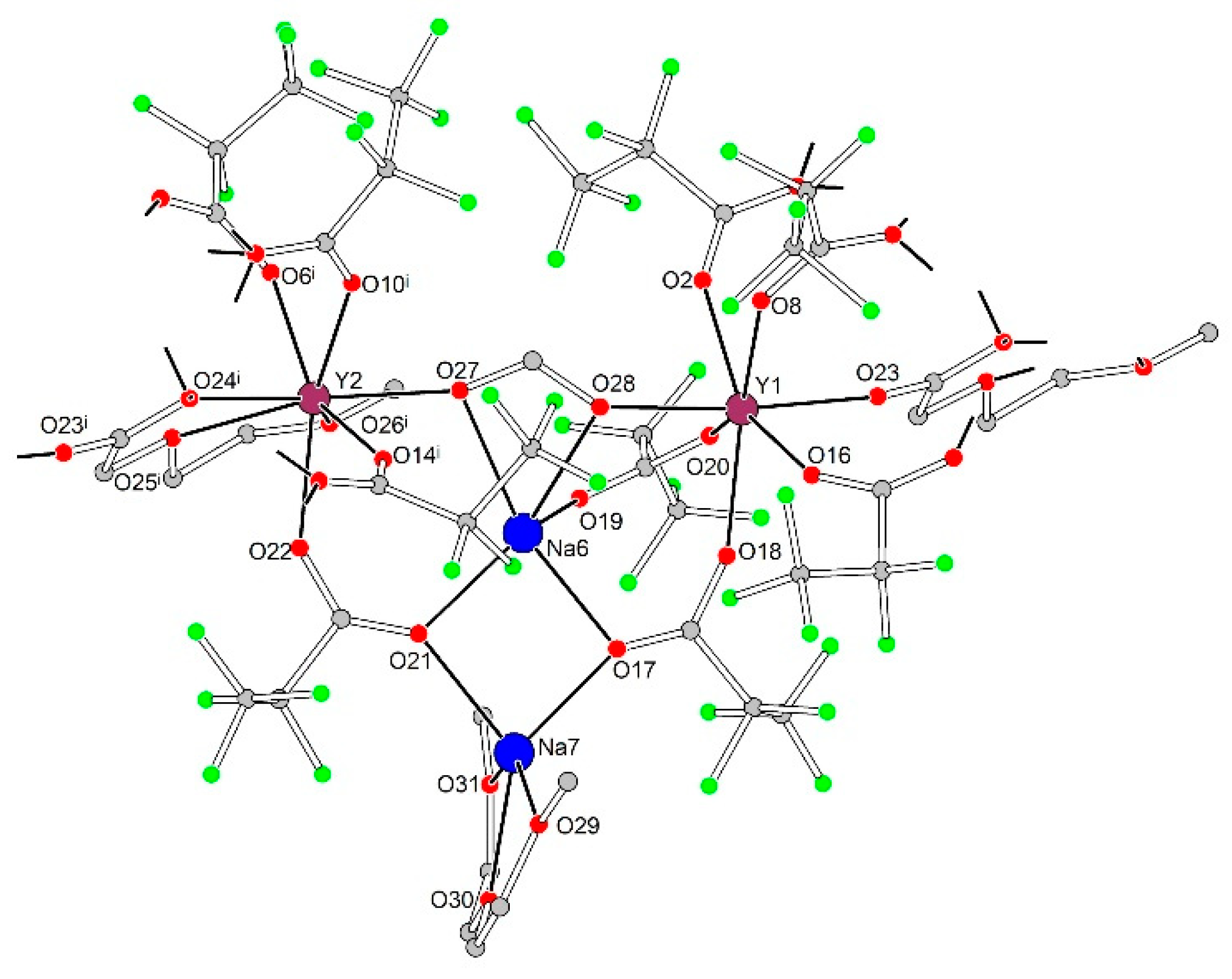
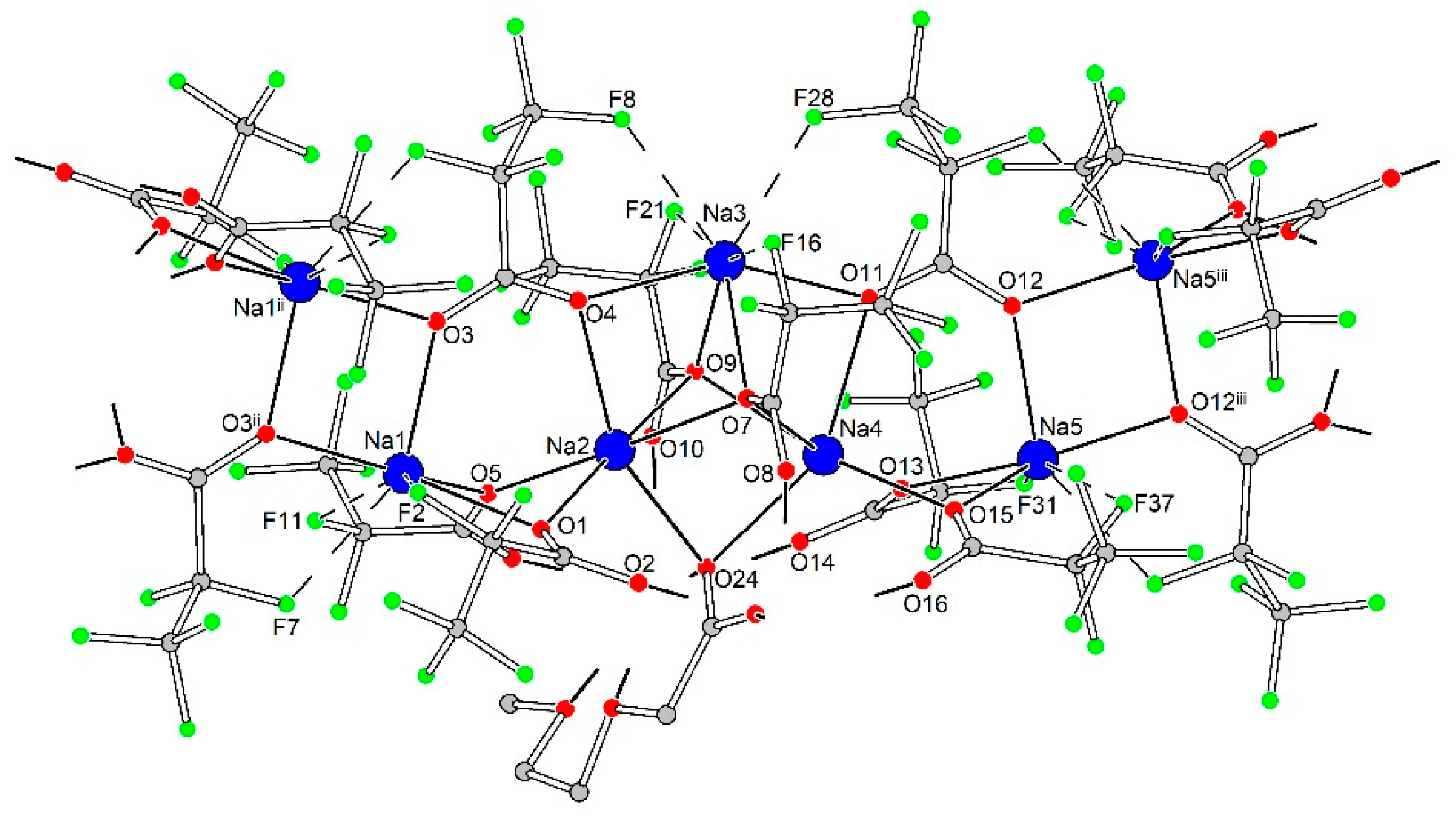
3.2.3. [Na7Ln2(pfp)11(form)(diglyme)(Meac)] (Ln = Y, Er, Yb) (3Ln)

The single crystals of the mixed-metal compound 3Ln were harvested from the gel-like mother liquor formed after solvent evaporation from the mixed-metal precursor solution of [Na(pfp)] and [Ln2(pfp)6(H2O)6], where Ln = Y0.78Yb0.20Er0.02; the same cation ratio was set up for Ln ions in the 3Ln structure. The asymmetric part of the triclinic unit cell contains seven Na atoms, two Ln atoms, eleven pfp anions, one diglyme ligand and additionally form and Meac anions. The 3Ln compound possesses a layered structure. Layers are formed due to the linking of the 1D polymeric {Na5(pfp)5} species and tetranuclear heterometallic {Na2Ln2(diglyme)(Meac)(pfp)6(form)} species via the bridging functions of Meac and pfp anions.
In tetranuclear species each cation, Ln1, Ln2, Na6, and Na7, exhibits a unique coordination environment (Figure 8, Table 4). The coordination environment of the Na6 cation is formed by chelating form anion (O27, O28) and O17, O19 and O21 atoms of three bridging pfp anions, while the Na7 cation is coordinated by the same O17 and O21 atoms of two pfp anions and additionally by chelating neutral diglyme ligand (O29, O30 and O31). Ln1 with a pentagonal bipyramidal environment (CN equals to 7) is coordinated by O2, O8, O16, O18, O20 and O23 atoms of six bridging pfp anions and by O28 atom of chelato-bridging form anion from the Na6 environment. Ln2, being in a triangular dodecahedral environment with CN equal to 8, is coordinated by O6i, O10i, O14i and O22 atoms of four bridging pfp anions, by O27 atom of form anion and by O24i, O25i and O26i atoms of chelating Meac anion.
The 1D polymeric {Na5(pfp)5} species in 3Ln contains Na1-Na5 cations with coordination environments of three types (Figure 9). Na1 and Na5 cations, both with CN equal to 4 + 3, are coordinated by four O-atoms of four bridging pfp anions, and by three additional F-atoms of –CF2– groups from coordinated pfp. The coordination environment of Na2 and Na4 cations is formed by six O-atoms of six bridging pfp anions. Finally, the Na3 cation with CN equal to 4 + 4 is coordinated by O4, O7, O9 and O11 atoms of four pfp anions as well as by F8, F16, F21 and F28 of the same pfp anions. One can virtually separate the polymeric {Na5(pfp)5} species into several corner-shared and face-shared binuclear building blocks with square {Na2O2} and trigonal bipyramidal {Na2O3} metal-oxygen cores, which were recently considered to be the most energetically favorable for Na-based coordination polymers [28]. The {Na5(pfp)5} chains act as ‘guide rods’ assembling the structure to 2D layers via bridging tetranuclear heterometallic {Na2Ln2(diglyme)(Meac)(pfp)6(form)} species (Figure 10). A similar feature was recently revealed by us for the 3D dense coordination polymer [HKCu2(prop)6] with non-fluorinated propionate ligands, where [HK(prop)2] chains were linked into a framework via binuclear [Cu2(prop)4] paddlewheel units [29]. One could expect a similar 3D structure for 3Ln, since Ln3+ ions also tend to form coordination polymers even with bulky anionic ligands [30,31,32]. However, simultaneous coordination of polydentate diglyme and Meac ligands along with bulky –C2F5 groups of pfp anions effectively shielded Ln3+ and Na+ cations and resulted in a 2D coordination polymer.

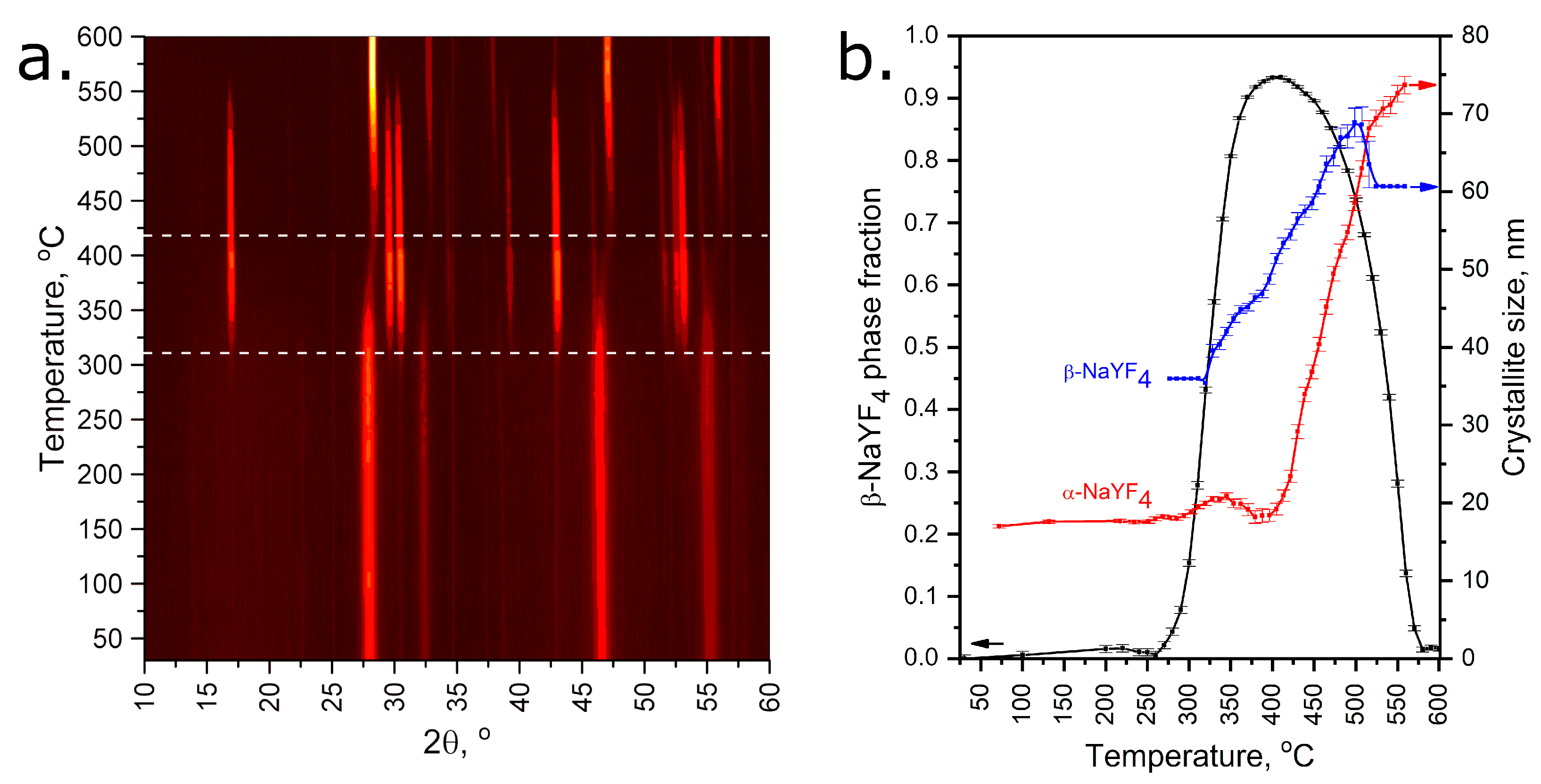
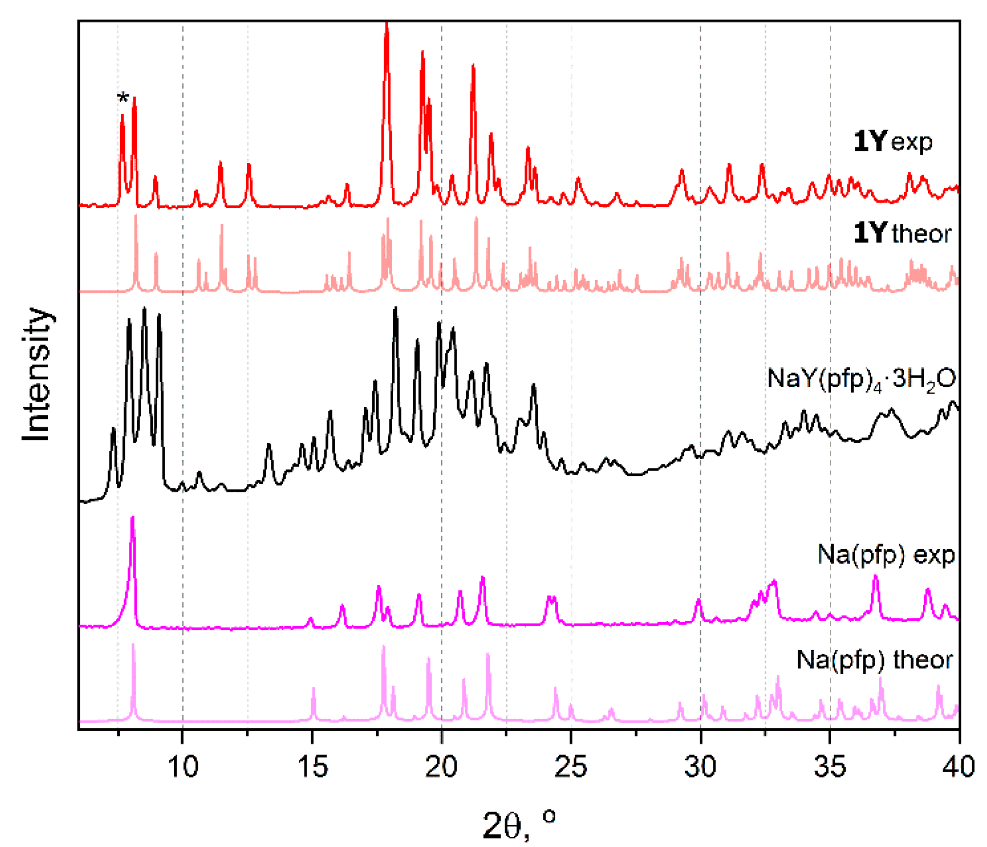
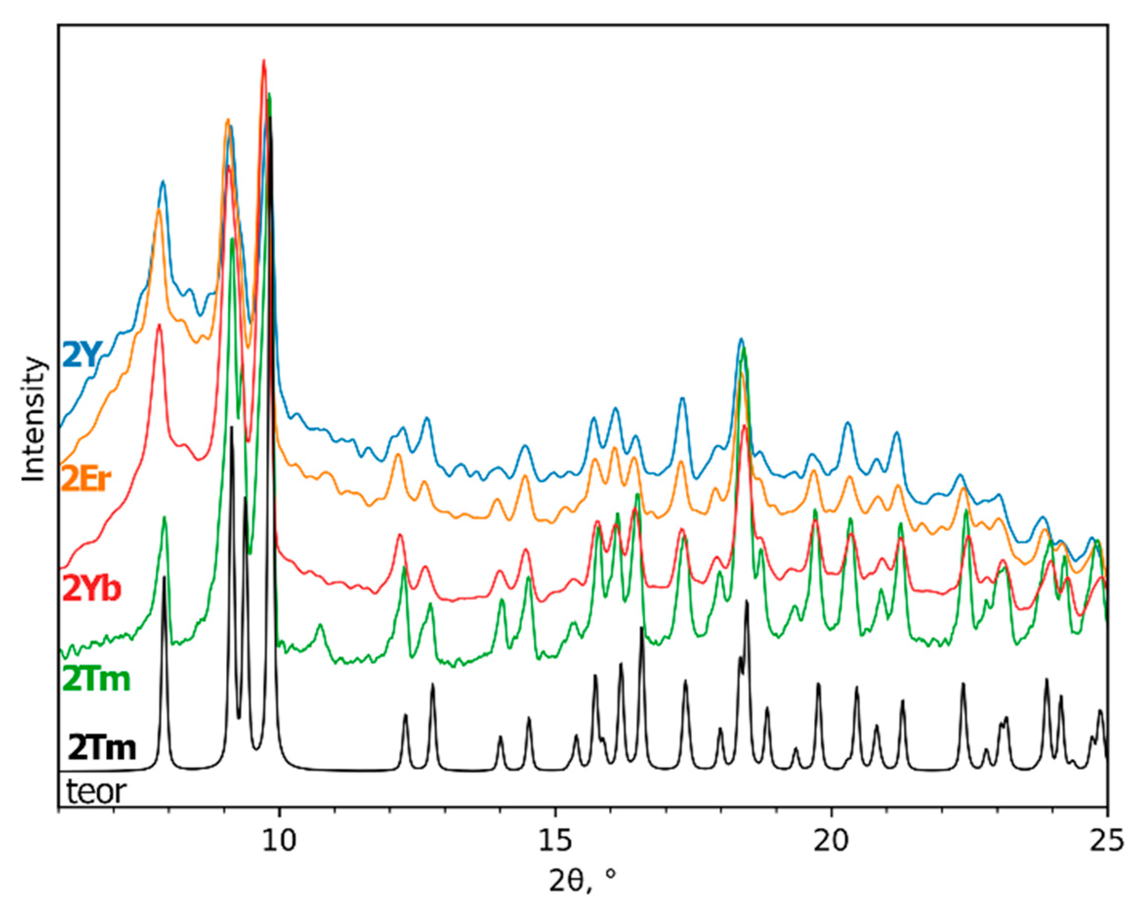
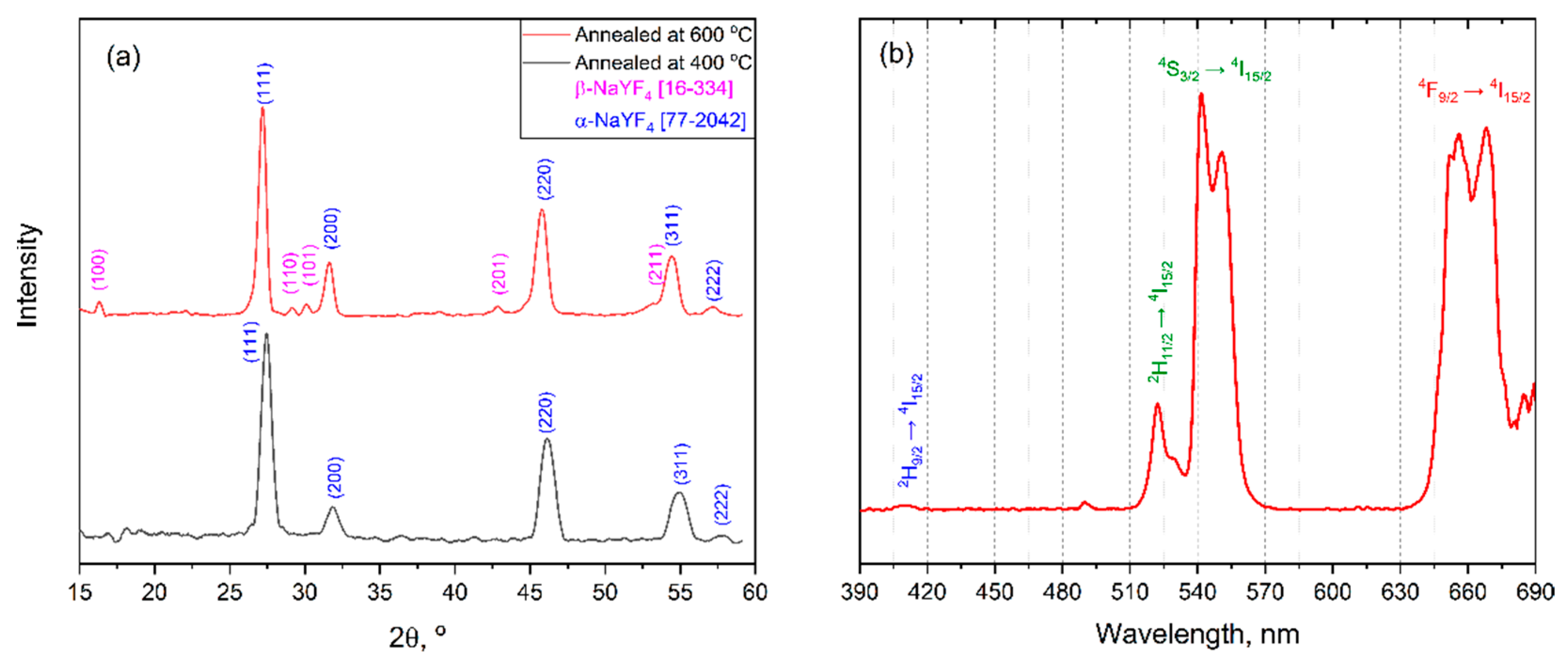
3.3. NaLnF4 Powders Preparation and Characterization

The high reactivity of perfluorinated precursors allows one to perform the chemical synthesis of NaLnF4 at temperatures as low as 300–400 °C. According to the phase diagram of the NaF–YF3 system, this should lead to the formation of hexagonal β-NaLnF4, which is stable up to 680–690 °C [33] and is considered the most suitable for UCL application [34]. However, weak diffusion during low temperature synthesis often leads to crystallization of the disordered cubic α-NaLnF4 phase of the fluorite type. Thus, the crystallization process of NaLnF4 prepared from the thermal decomposition of metal carboxylate precursors was studied by VT-PXRD (Figure 11).
According to the VT-PXRD data, two phase transformations of as-obtained NaYF4 occur in a temperature range of 25–600 °C. At 25–310 °C, the as-obtained sample contains almost pure metastable cubic α-NaYF4 phase with minor contents of a hexagonal β-NaYF4 one within the agreement with Ostwald’s step rule [35]. One can notice the broad peaks of α-NaYF4 at the lower temperatures, which confirms the poor crystallinity of the sample with an estimated crystallite size of less than 20 nm. Further heating activates the ion diffusion effects, and after 310 °C the cubic phase remarkably transforms into the thermodynamically stable hexagonal phase. This process also increases crystallinity, and the size of hexagonal crystallites increases to 70 nm. The maximum amount of hexagonal phase is observed in the 400–440 °C temperature range; however, traces of cubic phase still remain in the sample. Finally, further heating leads to the transformation of the hexagonal phase back to the high-temperature cubic phase with high crystallinity.

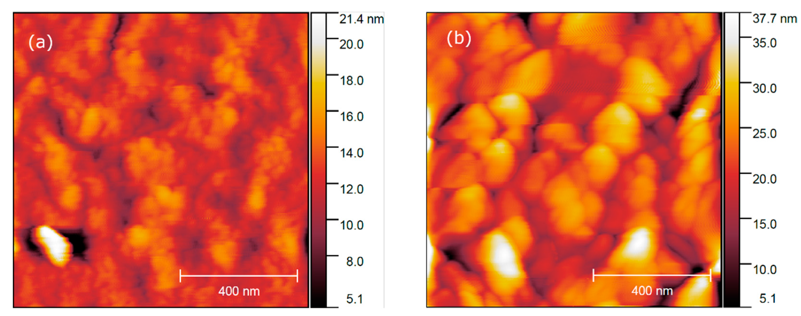
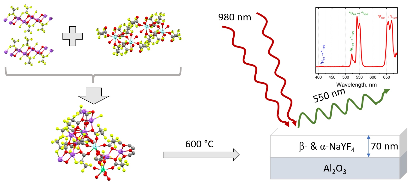
3.4. NaLnF4 Thin Films

The metal organic precursors described above were used for the deposition of complex fluoride thin films by MOCSD. At the first stage, a gel-like amorphous film is formed by the dip-coating technique from homogeneous precursor solution after solvent evaporation. The high viscosity of gel originating from the polymeric mixed-metal species in solution prevents the separation of precursor components and provides a uniformity of film composition. At the second stage, thermal decomposition (Equation (1) [12]) of deposited precursor occurs in the whole volume of the thin film, simultaneously resulting in randomly oriented NaLnF4 nanocrystals (Figure 12a). In addition, the amorphous precursor layer provides exceptional smoothness to the resulting film at lower temperatures.
NaLn(pfp)4 → NaLnF4 + CO + CO2 + C2F4 + …
Further AFM study of film morphology reveals that films after 400 °C annealing consist of 40–70 nm nanocrystals, which corresponds to the limited kinetics of the crystallization process at low temperature. The MOCSD films have a lower porosity and a smoother surface (root mean square roughness Sq = 2.7 nm for 5 × 5 μm2 area) than has been reported for sol–gel films (average roughness of 3.4 nm or 2 × 2 μm2 area) [36]. However, annealing at a higher temperature, e.g., 600 °C, initiates the grain growth up to 130–180 nm in lateral size (Figure 12b) and increases the overall roughness on the film (Sq = 26 nm). It should be also noted that the films have an equal thickness of ca. 73 nm.
GIXRD data (Figure 13a) confirms that both thin films consist of a polycrystalline NaLnF4 phase with a domination of cubic α-NaLnF4. It is worth noting that unlike the powder case, the hexagonal β-NaLnF4 appears as a minor component only in the film annealed at 600 °C. This indicates that the crystallization process in quasi-2D thin films is significantly slowed down with respect to the bulk state and further optimization of deposition conditions required for the preparation of pure β-NaLnF4 film by MOCSD.
Deposited thin films demonstrate an intense eye-visible up-conversion luminescence under 980 nm laser excitation despite small thickness and domination of cubic α-NaLnF4 (Figure 13b). The emission UCL spectrum contains typical emission bands which correspond to electron transitions for the Yb3+-Er3+ system (650, 525, 550 and 420 nm: |4F9/2> → |4I15/2>; |2H11/2> → |4I15/2>; |4S3/2> → |4I15/2>; |2H9/2> → |4I15/2>, respectively) [37]. It is worth noting that the relative intensities of green (|4S3/2> → |4I15/2>) and red (|4F9/2> → |4I15/2>) emission bands are similar to those in the UCL spectrum of β-NaY0.78Yb0.20Er0.02F4 film prepared by the sol–gel method [36].

4. Conclusions

Three new single-source precursors for an affordable method of fluoride film deposition were synthesized and characterized by the XRD and TG-DTA methods. According to single-crystal XRD experiments, individual lanthanide pentafluoropropionates in a crystalline state consist of isolated binuclear formula molecules Ln2(pfp)6(H2O)6 and Ln2(pfp)6(diglyme)6. Substitution of water molecules for diglyme retains the binuclear molecular structure, while the later reaction with Na(pfp) results in a stable solution precursor which crystallizes to [Na7Ln2(pfp)11(form)(diglyme)(Meac)] after organic ligand degradation. For the heterometallic complex (NaLn(pfp)4·3H2O), TG-DTA data confirmed the single-stage fluoride formation within a narrow temperature range, which is essential for homogeneous film deposition at low temperature. VT-PXRD study of as-obtained metal fluorides shows two phase transformations: poorly crystallized cubic NaYF4 into hexagonal NaYF4, and then back into a high-temperature cubic phase. Finally, the diglyme-containing single-source precursor solution allowed us to obtain a homogeneous and smooth NaLnF4 films with an eye-visible up-conversion luminescence under 980 nm laser excitation. This work was more focused on precursor design strategy for the MOCSD of complex fluorides; further optimization of film thickness and heat-treatment conditions is therefore necessary to enhance the efficiency of up-conversion.

Author Contributions

Conceptualization, D.T.; methodology, D.T., A.S. and D.G.; software, D.T., A.A.; formal analysis, D.T., A.S. and D.G.; investigation A.S., D.G., A.A. and D.B.; resources, D.T.; data curation, D.T., A.S. and D.G.; writing—original draft preparation, A.S., D.T. and D.G.; writing—review and editing, D.T. and D.G.; visualization, A.S. and D.G.; supervision, D.T.; project administration, D.T.; funding acquisition, D.T. All authors have read and agreed to the published version of the manuscript.

Funding

Artem Shevchenko acknowledges the DFG-Grant BE 7407/1-1 for funding of in situ PXRD data collection.

Institutional Review Board Statement

Not applicable.

Informed Consent Statement

Not applicable.

Data Availability Statement

The primary data presented in this study are available on request from the corresponding author.

Acknowledgments

Dmitry Tsymbarenko acknowledges support from M.V. Lomonosov Moscow State University Program of Development. Artem Shevchenko is very thankful to Sebastian Bette (Max Plank Institute for Solid State Research (MPI-FKF), Stuttgart, Germany) for his help in conducting PXRD experiments.

Conflicts of Interest

The authors declare no conflict of interest.

References

  1. Joubert, M.-F. Photon avalanche upconversion in rare earth laser materials. Opt. Mater. 1999, 11, 181–203. [Google Scholar] [CrossRef]
  2. Lui, Y.; Chem, W.; Wang, S.; Joly, A.G. X-ray luminescence of LaF3:Tb3+ and LaF3: Ce3+,Tb3+ water-soluble nanoparticles. J. Appl. Phys. 2008, 103, 063105. [Google Scholar]
  3. Yang, L.W.; Han, H.L.; Zhang, Y.Y.; Zhong, J.X. White Emission by Frequency Up-Conversion in Yb3+-Ho3+-Tm3+ Triply Doped Hexagonal NaYF4 Nanorods. J. Phys. Chem. C 2009, 113, 18995–18999. [Google Scholar] [CrossRef]
  4. Zhang, P.; Chen, H.; Yang, Y.; Zhao, D.; Jia, Z.; Zheng, K.; Qin, G.; Qin, W. 3D up-conversion display of NaYF4-PMMA co-valent-linking nanocomposites. J. Alloys Compd. 2018, 753, 725–730. [Google Scholar] [CrossRef]
  5. Menyuk, N.; Dwight, K.; Pierce, J.W. NaYF4: Yb, Er—An efficient upconversion phosphor. Appl. Phys. Lett. 1972, 21, 159–161. [Google Scholar] [CrossRef]
  6. Tsuyoshi, K.; Yamamoto, H.; Otomo, Y. NaLnF4:Yb3+, Er3+ (Ln: Y, Gd, La): Efficient Green-Emitting Infrared-Excited Phos-phors. J. Electrochem. Soc. 1972, 119, 1561. [Google Scholar]
  7. Pinol, L.; Rebello, K.; Caruso, K.; Francomacaro, A.S.; Coles, G.L. Physical vapor deposition and patterning of calcium fluoride films. J. Vac. Sci. Technol. A 2011, 29, 21001. [Google Scholar] [CrossRef]
  8. Ylilammi, M.; Ranta-aho, T. Metal Fluoride Thin Films Prepared by Atomic Layer Deposition. J. Electrochem. Soc. 1994, 141, 1278. [Google Scholar] [CrossRef]
  9. Jia, H.; Xu, C.; Wang, J.; Chen, P.; Liu, X.; Qui, J. Synthesis of NaYF4:Yb–Tm thin film with strong NIR photon up-conversion photoluminescence using electro-deposition method. CrystEngComm 2014, 16, 4023–4028. [Google Scholar] [CrossRef]
  10. Battiato, S.; Rossi, P.; Paoli, P.; Malandrino, G. Heterobimetallic Sodium Rare-Earth Complexes: “Third-Generation” MOCVD Precursors for the Deposition of NaREF4 (RE = Y, Gd) Films. Inorg. Chem. 2018, 57, 15035–15039. [Google Scholar] [CrossRef]
  11. Barranco, J.; Méndez-Blas, A.; Calixto, M.E. Structural, morphology and optical properties of NaYF4 thin films doped with trivalent lanthanide ions. J. Mater. Sci. Mater. Electron. 2019, 30, 4855–4866. [Google Scholar] [CrossRef]
  12. Rillings, K.; Roberts, J. A thermal study of the trifluoroacetates and pentafluoropropionates of praseodymium, samarium and erbium. Thermochim. Acta 1974, 10, 269–277. [Google Scholar] [CrossRef]
  13. Hercules, D.A.; Parrish, C.A.; Sayler, T.S.; Tice, K.T.; Williams, S.M.; Lowery, L.E.; Brady, M.E.; Coward, R.B.; Murphy, J.A.; Hey, T.A.; et al. Preparation of tetrafluoroethylene from the pyrolysis of pentafluoropropionate salts. J. Fluor. Chem. 2017, 196, 107–116. [Google Scholar] [CrossRef] [Green Version]
  14. Chen, X.; Peng, D.; Ju, Q.; Wang, F. Photon upconversion in core–shell nanoparticles. Chem. Soc. Rev. 2015, 44, 1318–1330. [Google Scholar] [CrossRef]
  15. Ayadi, H.; Fang, W.; Mishra, S.; Jeanneau, E.; Ledoux, G.; Zhang, J.; Daniele, S. Influence of Na+ion doping on the phase change and upconversion emissions of the GdF3: Yb3+, Tm3+nanocrystals obtained from the designed molecular precursors. RSC Adv. 2015, 5, 100535–100545. [Google Scholar] [CrossRef]
  16. Mishra, S.; Jeanneau, E.; Bulin, A.-L.; Ledoux, G.; Jouguet, B.; Amans, D.; Belsky, A.; Daniele, S.; Dujardin, C. A molecular precursor approach to monodisperse scintillating CeF3 nanocrystals. Dalton Trans. 2013, 42, 12633–12643. [Google Scholar] [CrossRef]
  17. Grebenyuk, D.; Ryzhkov, N.; Tsymbarenko, D. Novel mononuclear mixed ligand complexes of heavy lanthanide trifluoro-acetates with diethylenetriamine. J. Fluor. Chem. 2017, 202, 82–90. [Google Scholar] [CrossRef]
  18. Chen, Y.; Mishra, S.; Ledoux, G.; Jeanneau, E.; Daniel, M.; Zhang, J.; Daniele, S. Direct synthesis of hexagonal NaGdF4 nano-crystals from a single-source precursor: Upconverting NaGdF4:Yb3+,Tm3+ and its composites with TiO2 for near-IR-driven photocatalysis. Chem. Asian J. 2014, 9, 2415–2421. [Google Scholar] [CrossRef]
  19. Mishra, S.; Daniele, S.; Ledoux, G.; Jeanneau, E.; Joubert, M.-F. Heterometallic−complexes as novel single-source precursors for upconverting NaYF4 co-doped with Yb and Er/Tm ions. Chem. Commun. 2010, 46, 3756–3758. [Google Scholar] [CrossRef]
  20. Mishra, S.; Ledoux, G.; Jeanneau, E.; Daniele, S.; Joubert, M.-F. Novel heterometalorganic complexes as first single source precursors for up-converting NaY(Ln)F4 (Ln = Yb, Er Tm) nanomaterials. Dalton Trans. 2012, 41, 1490–1502. [Google Scholar] [CrossRef]
  21. Petříček, V.; Dušek, M.; Palatinus, L. Crystallographic Computing System JANA2006: General features. Z. Krist.-Cryst. Mater. 2014, 229, 345–352. [Google Scholar] [CrossRef]
  22. Sheldrick, G.M. SADABS V. 2.01, Bruker/Siemens Area Detector Absorption Correction Program; Bruker AXS: Madison, WI, USA, 1998. [Google Scholar]
  23. Sheldrick, G.M. CELL_NOW; Georg-August-Universität: Göttingen, Germany, 2008. [Google Scholar]
  24. Sheldrick, G.M. TWINABS 2012/1; Bruker AXS: Madison, WI, USA, 2012. [Google Scholar]
  25. Sheldrick, G.M. SHELXTL, Ver. 5.10. In Structure Determination Software Suite; Bruker AXS: Madison, WI, USA, 1998. [Google Scholar]
  26. Tang, S.; Zhao, H. Glymes as versatile solvents for chemical reactions and processes: From the laboratory to industry. RSC Adv. 2014, 4, 11251–11287. [Google Scholar] [CrossRef] [PubMed]
  27. Rohde, A.; Urland, W. Synthese, Kristallstruktur und magnetisches Verhalten von Gd(CF3CF2COO)3(H2O)3. Z. Anorg. Allg. Chem. 2006, 632, 1141–1144. [Google Scholar] [CrossRef]
  28. Tsymbarenko, D.M.; Korsakov, I.E.; Lyssenko, K.A.; Troyanov, S.I. One-dimensional coordination polymers in the crystal structures of sodium and potassium acetylacetonates. Polyhedron 2015, 92, 68–76. [Google Scholar] [CrossRef]
  29. Kendin, M.; Nikiforov, A.; Svetogorov, R.; Degtyarenko, P.; Tsymbarenko, D. A 3D-coordination polymer assembled from copper propionate paddlewheels and potassium propionate 1D-polymeric rods possessing a temperature-driven sin-gle-crystal-to-single-crystal phase transition. Cryst. Growth Des. 2021, 21, 6183–6194. [Google Scholar] [CrossRef]
  30. Tsymbarenko, D.; Martynova, I.; Grebenyuk, D.; Shegolev, V.; Kuzmina, N. One-dimensional coordination polymers of whole row rare earth tris-pivalates. J. Solid State Chem. 2018, 258, 876–884. [Google Scholar] [CrossRef]
  31. Grebenyuk, D.; Zobel, M.; Polentarutti, M.; Ungur, L.; Kendin, M.; Zakharov, K.; Degtyarenko, P.; Vasiliev, A.; Tsymbarenko, D. A Family of Lanthanide Hydroxo Carboxylates with 1D Polymeric Topology and Ln4 Butterfly Core Exhibits Switchable Supramolecular Arrangement. Inorg. Chem. 2021, 60, 8049–8061. [Google Scholar] [CrossRef]
  32. Grebenyuk, D.; Tsymbarenko, D.; D. Synthesis and crystal structure of polymeric erbium cyclohexanecarboxylate with an unusual geometry of the polymer chain. J. Struct. Chem. 2022, 63, 3. [Google Scholar]
  33. Thoma, R.E.; Hebert, G.M.; Insley, H.; Weaver, C.F. Phase Equilibria in the System Sodium Fluoride-Yttrium Fluoride. Inorg. Chem. 1963, 2, 1005–1012. [Google Scholar] [CrossRef]
  34. Krämer, K.W.; Biner, D.; Frei, G.; Güdel, H.U.; Hehlen, M.P.; Lüthi, S.R. Hexagonal Sodium Yttrium Fluoride Based Green and Blue Emitting Upconversion Phosphors. Chem. Mater. 2004, 16, 1244–1251. [Google Scholar] [CrossRef]
  35. Van Santen, R.A. The Ostwald step rule. J. Phys. Chem. 1984, 88, 5768–5769. [Google Scholar] [CrossRef]
  36. Park, H.; Yoo, G.Y.; Kim, M.-S.; Kim, K.; Lee, C.; Park, S.; Kim, W. Thin film fabrication of upconversion lanthanide-doped NaYF4 by a sol-gel method and soft lithographical nanopatterning. J. Alloys Compd. 2017, 728, 927–935. [Google Scholar] [CrossRef]
  37. Bünzli, J.C.G.; Eliseeva, S.V. Basics of Lanthanide Photophysics. In Lanthanide Luminescence. Springer Series on Fluorescence (Methods and Applications); Hänninen, P., Härmä, H., Eds.; Springer: Berlin/Heidelberg, Germany, 2010; Volume 7. [Google Scholar] [CrossRef] [Green Version]
Figure 1. Calculated and experimental PXRD patterns of [Y2(pfp)6(H2O)6] (1Y), Na(pfp) and [NaY(pfp)4(H2O)3] (black). Symbol * indicates the peak of the by-product phase of Y(pfp)3·nH2O with a polymeric structure.
Metals 12 00488 g001
Figure 2. TG-curves for the thermal decomposition of individual and heterometallic pentafluoropropionates heated at 10°/min in air atmosphere. Vertical dotted lines correspond to the end of thermal decomposition.
Metals 12 00488 g002
Figure 3. Experimental PXRD patterns of [Ln2(pfp)6(diglyme)2] (2Ln, Ln = Y, Er, Tm, Yb) and theoretical PXRD pattern of 2Tm at room temperature.
Metals 12 00488 g003
Figure 4. Molecular geometry in 1Y structure. Y atoms are depicted at 50% probability, light atoms at 30% probability. Colour code: Y, cyan; O, red; F, green; C, grey; H, white. H atoms are omitted partially for clarity. Symmetry code (i): −x, 1 − y, 1 − z.
Metals 12 00488 g004
Figure 5. Topology of layer in ab plane formed by molecular species in crystal structure of 1Y. Colour code: Y, cyan; O, red; F, green; C, grey. H atoms are omitted for clarity. Dashed lines show H-bonds.
Metals 12 00488 g005
Figure 6. Tm2(pfp)6(diglyme)2 binuclear molecule. Tm atoms are depicted at 50% probability, light atoms at 30% probability. Colour code: Tm, violet; O, red; F, green; C, grey. H atoms are omitted for clarity. Symmetry code (i): 1 − x, 1 − y, 2 − z.
Metals 12 00488 g006
Figure 7. Packing diagram of [Tm2(pfp)6(diglyme)2] molecules within bc plane in structure 2Tm. Colour code: Tm, violet; O, red; F, green; C, grey; H, white.
Metals 12 00488 g007
Figure 8. Geometry of {Na2Ln2(diglyme)(Meac)(pfp)6(form)} species in the crystal structure of 3Ln. Colour code: Y|Yb|Er, burgundy; Na, blue; O, red; F, green; C, grey. H-atoms are omitted for clarity.
Metals 12 00488 g008
Figure 9. Geometry of 1D polymeric {Na5(pfp)5} species in the crystal structure of 3Ln. Colour code: Na, blue; O, red; F, green; C, grey. H-atoms are omitted for clarity. Dash lines show Na···F contacts.
Metals 12 00488 g009
Figure 10. Topology of 2D layer in crystal structure of 3Ln. Colour code: Y|Yb|Er, burgundy; Na, blue; O, red; F, green; C, grey. Perfluoroethyl groups of pfp anions are depicted in semitransparent mode. H-atoms are omitted for clarity.
Metals 12 00488 g010
Figure 11. VT-PXRD patterns of as-obtained NaYF4 (a) and result of Rietveld refinement (b). Horizontal dashed lines at 310 and 420 °C correspond to the beginning of the crystallization process of the hexagonal and cubic phases, respectively. XRD patterns recorded at 270–320 °C and 560–600 °C temperature ranges were refined with a fixed crystallite size of β-NaYF4 due to its minor content.
Metals 12 00488 g011
Figure 12. AFM height profiles of fluoride thin films, annealed at 400 °C and 600 °C (a) and (b), respectively.
Metals 12 00488 g012
Figure 13. (a) GIXRD patterns (ω = 0.5°) of thin films annealed at 400 °C (black) and 600 °C (orange); (b) up-conversion luminescence spectra from thin film under 980 nm laser excitation.
Metals 12 00488 g013
Table 1. Crystal and refinement data for the crystal structure 1Y, 2Tm and 3Ln.
Compound1Y2Tm3Ln
FormulaC18H12F30O18Y2C30H28F30O18Tm2C45H24F55Na7O31Y1.56Yb0.40Er0.04
Formula weight1264.101584.382481.18
DiffractometerBruker D8 QUESTBruker Smart APEX DUOBruker D8 QUEST
Data collection methodω-scansω-scansω-scans
Temperature (K)100(2)120(2)150(2)
Crystal systemTriclinicMonoclinicTriclinic
Space groupP1P21/cP1
a (Å)9.062(4)12.036(2)12.8526(12)
b (Å)10.202(5)18.553(3) 14.7852(13)
c (Å)11.113(6)12.084(2)23.055(2)
α (°)90.78(2)90100.753(2)
β (°)110.03(2)113.849(3) 101.520(2)
γ (°)106.05(2)9091.705(2)
V (Å3)921.0(8)2468.1(7)4207.3(7)
Z122
Color, habitColorless, plateColorless, plateColorless, block
Crystal dimensions (mm)0.24 × 0.17 × 0.060.31 × 0.30 × 0.120.269 × 0.172 × 0.097
Dcalc (g·cm−3)2.2792.1321.959
μ (mm−1)3.3603.7511.785
Unique reflections (Rint)4731 (0.1108)5948 (0.0499)18,172 (0.1015)
Observed reflections [I > 2σ(I)]33274324 9391
Parameters, restrains307, 0363, 01262, 179
R1[I > 2σ(I)], ωR20.0704, 0.17000.0349, 0.07900.0901, 0.2755
Goodness-of-fit on F21.0391.0661.020
Absorption correctionSADABSSADABSTWINABS
Tmin, Tmax0.499, 0.8240.2543, 0.65930.5359, 0.7455
ρmin, ρmax (eÅ−3)−1.529, 1.861−1.923, 1.996 −0.860, 1.808
Table 2. Selected interatomic distances (Å) in 1Y. Symmetry code (i): 1 − x, 1 − y, 2 − z.
ParameterDistance
Ln1–O1 2.293(4)
Ln1–O2 i2.306(4)
Ln1–O3 2.322(4)
Ln1–O5 2.312(4)
Ln1–O4 i2.383(4)
Ln1–O7 2.339(4)
Ln1–O8 2.411(4)
Ln1–O9 2.339(4)
Ln1···Ln1 i4.483(2)
D···A distance in hydrogen bonds
O7–H1···O6 ii2.721(5)
O8–H3···O4 iii2.873(7)
O9–H6···O62.629(6)
Symmetry codes: (i) −x, 1 − y, 1 − z; (ii) 1 − x, 2 − y, 1 − z; (iii) 1 − x, y, z.
Table 3. Selected interatomic distances (Å) in 2Tm. Symmetry code (i): 1 − x, 1 − y, 2 − z.
Parameter2Tm
Tm1–O1 2.343(4)
Tm1–O2 i2.278(4)
Tm1–O3 2.245(3)
Tm1–O5 2.304(3)
Tm1–O6 i2.279(3)
Tm1–O7 2.432(3)
Tm1–O8 2.399(3)
Tm1–O9 2.405(3)
Tm1···Tm1 i4.5199(6)
Table 4. Selected interatomic distances (Å) in 3Ln structure. Symmetry codes: (i) x − 1, y, z; (ii) 2 − x, −y, 2 − z; (iii) 2 − x, −y, 1 − z.
ParameterDistanceParameterDistanceParameterDistanceParameterDistanceParameterDistance
Distances in 1D polymeric {Na5(pfp)5}species
Na1–O12.352(9)Na2–O12.621(9)Na3–O42.338(7)Na4–O72.381(8)Na5–O122.324(11)
Na1–O32.345(10)Na2–O42.352(9)Na3–O72.408(9)Na4–O92.455(8)Na5–O132.315(12)
Na1–O3 ii2.284(8)Na2–O52.307(10)Na3–O92.326(9)Na4–O112.429(10)Na5–O12 iii2.291(8)
Na1–O52.373(9)Na2–O72.409(9)Na3–O112.318(8)Na4–O132.287(10)Na5–O152.352(10)
Na1–F22.699(11)Na2–O92.370(8)Na3–F82.602(9)Na4–O152.319(9)Na5–F26 iii2.617(10)
Na1–F7 ii2.639(10)Na2–O242.287(9)Na3–F162.478(11)Na4–O232.871(9)Na5–F312.879(15)
Na1–F112.678(12)--Na3–F212.767(10)Na4–O242.498(9)Na5–F372.817(14)
----Na3–F282.558(11)----
Distances in tetranuclear heterometallic {Na2Ln2(diglyme)(Meac)(pfp)6(form)} species
Na6–O172.288(11)Na7–O172.233(12)Y1–O22.266(8)Y2–O6 i2.300(7)--
Na6–O192.34(2)Na7–O212.318(11)Y1–O82.311(11)Y2–O10 i2.319(9)--
Na6–O212.262(10)Na7–O292.31(2)Y1–O162.267(9)Y2–O14 i2.282(10)--
Na6–O272.402(12)Na7–O302.289(18)Y1–O182.252(11)Y2–O222.291(9)--
Na6–O282.374(12)Na7–O312.39(2)Y1–O202.334(12)Y2–O24 i2.325(8)--
--Na7–F512.938(12)Y1–O232.226(8)Y2–O26 i2.429(12)--
----Y1–O282.229(8)Y2–O272.259(8)--
Publisher’s Note: MDPI stays neutral with regard to jurisdictional claims in published maps and institutional affiliations.

