Article

Optimizing the Electrical and Mechanical Properties of Cu-Cr Alloys by Hf Microalloying

Key Laboratory for Light-Weight Materials, College of Materials Science and Engineering, Nanjing Tech University, Nanjing 211816, China
*
Author to whom correspondence should be addressed.
Metals 2022, 12(3), 485; https://doi.org/10.3390/met12030485
Submission received: 7 February 2022 / Revised: 28 February 2022 / Accepted: 10 March 2022 / Published: 13 March 2022

Abstract

:
Cu-0.4Cr (wt.%) alloys with the microalloying of Hf elements were subjected to a modified rolling–aging process to achieve high strength, high electrical conductivity and high ductility simultaneously. Transmission electron microscopy and X-ray line broadening analysis were conducted to characterize the microstructures of these alloys. Deformation twins and high-density dislocations were introduced into the copper alloys via the modified rolling–aging process and the microalloying of Hf, improving the mechanical properties of copper alloys. The Cu-Cr-Hf alloy with a reduced Hf content performed well in terms of strength, electrical conductivity and ductility. The microalloying of 0.4 wt.% Hf in the Cu-0.4Cr alloy was sufficient to achieve a good combination of high tensile strength (593 MPa), high uniform elongation (~5%) and high electrical conductivity (80.51% IACS).

1. Introduction

Cu-Cr system alloys, including Cu-Cr, Cu-Cr-Zr and Cu-Cr-Zr-Mg-Si alloys and so on, have been widely used in many electronic and electrical industries [1,2,3] because of their high strength and high electrical conductivity. Among various strengthening strategies, precipitation strengthening seems to be one of the most effective ones for the simultaneous achievement of high strength and high electrical conductivity. On the one hand, nanoprecipitates play a significant role in enhancing mechanical strength [4]. On the other hand, the depletion of solutes in a copper matrix increases the electrical conductivity significantly [5]. The Cr phase is one of the most important precipitates in Cu-Cr system alloys. In the past few decades, there has been a dispute regarding the Cr precipitate as to whether it has a body-centered-cubic (bcc) or face-centered-cubic (fcc) structure. Fujii et al. argued that the crystal structure of the Cr phases in Cu-Cr alloys was bcc even in the early stage of aging [6]. However, subsequent studies on Cu-Cr-Zr [7], Cu-Cr-Zr-Fe [8] and Cu-Cr-Zr-Mg-Si [9] alloys showed that initial precipitates were the ordered fcc Cr phase, having a cube-on-cube orientation with the copper matrix. As the aging treatment goes on, these fcc Cr phases will transform into the bcc structure with a Nishiyama–Wassermann or Kurdjumov–Sachs orientation with the copper matrix [7]. The alloying elements, such as the Zr or Hf elements, tend to segregate at the Cu/Cr interfaces and thus impede the coarsening of the Cr phase, contributing to the increase in tensile strengths [10,11]. Hafnium (Hf) has many similarities with Zr because of their similar crystal structure and same group. Both Hf and Zr additions can elevate the softening temperature of copper alloys [12]. The biggest difference between the Zr and Hf element is that the maximum solubility of Hf (0.4 at.% [13]) in copper is higher than that of Zr (0.12 at.% [14]).
It is generally deemed correct that higher solute content in the matrix will produce a higher fraction of precipitates during the aging treatment, resulting in a more pronounced precipitation strengthening. Following this strategy, Shangina et al. developed a Cu-0.7Cr-0.9Hf (wt.%) alloy subjected to severe plastic deformation [2,12]. Although excellent comprehensive performance in tensile strength (605 MPa) and electrical conductivity (78% IACS) was obtained [2], excess Hf element increases the costs and aggravates the resource consumption. To avoid resource exhaustion and to lower the costs, reducing the alloy content and optimizing the process seem to be promising ways to fabricate high-performance materials. One of the most common methods of preparing copper alloys with high strength and high electrical conductivity is thermo-mechanical treatment (i.e., solution treatment, cold rolling and aging). However, this one-step rolling–aging process fails to produce enough dislocations or nano-twins to elevate the mechanical properties further. If a portion of nano-precipitates form in the interval of cold rolling, these nano-precipitates will act as obstacles and sources of dislocations during the subsequent rolling, promoting the generation of dislocations. Following this strategy, a modified rolling–aging process is developed to obtain the simultaneous achievement of high strength and high electrical conductivity.
In this study, we aimed to develop a high-performance Cu-Cr-Hf alloy containing less Hf element to reduce the costs and resource consumption. The effects of the Hf element on the tensile strength, uniform elongation and electrical conductivity were investigated.

2. Materials and Methods

The alloys with nominal compositions of Cu-0.4Cr-0.2Hf and Cu-0.4Cr-0.4Hf (all in mass fraction hereafter) were melted via a vacuum medium frequency induction furnace (ZG-0.01L, Beijing Qianlan Nano Technology Development Co., Ltd., Beijing, China). The Cu-16 wt.% Hf master alloys were pre-prepared in a non-consumable vacuum arc furnace (custom-built, Kejing Automation Equipment Co., Ltd., Shenyang, China). Electrolytic copper (>99.97 wt.%), pure chromium (>99.8 wt.%) and Cu-16 wt.% Hf master alloys were melted in a graphite furnace and then cast in an iron mold at 1200 °C. The size of the ingot s was 40 × 50 × 120 mm3. The element content of the ingots was analyzed via X-ray fluorescence Spectrometer (XRF-1800, Shimadzu, Kyoto, Japan) to identify the actual chemical compositions of the ingots. The actual chemical compositions of the ingots were Cu-0.39Cr-0.21Hf and Cu-0.39Cr-0.38Hf, respectively, approaching the nominal compositions. The ingots were subjected to homogenization at 960 °C for 24 h, hot rolling at 850 °C with a thickness reduction of 30%, solution treatment at 972 °C for 60 min, and finally, water-quenching in sequence. The homogenization and solution treatment were conducted using a vacuum resistance furnace (ZMF-1200C-M, Anhui Beiyike Equipment Technology Co., Ltd., Hefei, China). The process flow chart is shown in Figure 1. Two different rolling–aging processes were explored. Process I was a one-step rolling–aging treatment (denoted as S1) including cold rolling with 90% reduction in thickness and aging at 450 °C. Process II was a two-step rolling–aging treatment (denoted as S2) including a first cold rolling with 30% reduction in thickness, a first aging at 450 °C for 120 min, a second cold rolling with 60% reduction in thickness and a second aging at 450 °C. The Cu-0.4Cr-0.2Hf alloys were subjected to Process I (denoted as Cu-0.4Cr-0.2Hf-S1). The Cu-0.4Cr-0.4Hf plate was cut into two parts. One part was subjected to Process I (denoted as Cu-0.4Cr-0.4Hf-S1); the other part was subjected to Process II (denoted as Cu-0.4Cr-0.4Hf-S2). The aging treatments were performed in a tubular electric resistance furnace with an accuracy of ±1 °C (BTF-1200C, Anhui Beiyike Equipment Technology Co., Ltd., Hefei, China). The final aging duration of both S1 and S2 samples depended on the final electrical conductivities. A series of isothermal aging treatments at 450 °C were conducted to raise the electrical conductivity. The shortest duration elevating the electrical conductivity over 80% IACS was defined as the optimal duration. Following this principle, the final aging durations of the Cu-0.4Cr-0.2Hf-S1, Cu-0.4Cr-0.4Hf-S1 and Cu-0.4Cr-0.4Hf-S2 were 90 min, 120 min and 90 min, respectively.
A transmission electron microscope (TEM, Talos F200x, Thermo Fisher Scientific Co., Hillsboro, OR, USA) was operated at 300 kV for microstructural characterizations. A Gatan PIPS 691 ion polishing system was used to prepare the foils for TEM. The convolutional multiple whole profile (CMWP) method was used to calculate the dislocation densities [15,16]. Dogbone tensile samples with a cross-section of 1.7 mm × 6 mm and a gauge length of 30 mm were cut from the plates using the electric spark cutting machine, according to the ASTM-E8 standard test methods for tension testing of metallic materials. These samples were tested utilizing a tensile machine (Instron 5500R, Instron Co., Norwood, MA, USA) with an initial displacement rate of 2 mm/min at room temperature. The strain was measured with a mechanical extensometer (Instron, Instron Co., Norwood, MA, USA). Samples were tensile-tested three times under each condition, and the values of their properties were calculated by averaging the test results. A Sigmascope SMP 350 (Helmut Fischer GmbH, Sindelfingen, Germany) was used for the electrical conductivity measurements. The size of each sample was 20 × 20 × 1.7 mm2. At least 8 measurements were taken to obtain an average value.

3. Results

Figure 2 shows the typical tensile curves of Cu-0.4Cr-0.2Hf-S1 and Cu-0.4Cr-0.4Hf-S1. The tensile strength of the Cu-Cr-Hf alloys increases with the increase in Hf content from 0.2% to 0.4%. The tensile strength of the Cu-0.4Cr-0.4Hf alloy subjected to cold rolling with 90% reduction already reaches 568 MPa, approaching the required mechanical properties. Although the art of alloying tailors the mechanical properties of metals, excess alloying elements increase both the costs and the environmental burden. A proper adaptation of materials processing, an alternative to alloying, becomes another effective strategy to modify the mechanical properties. Based on this idea, a modified rolling–aging process was used to enhance the tensile performance of Cu-0.4Cr-0.4Hf alloys further.
Figure 3a illustrates the typical tensile curves of both as-rolled and aged Cu-0.4Cr-0.4Hf alloys, in which the uniform elongations are labeled by rectangles. Figure 3b shows the strain hardening rate curves of the as-rolled and aged Cu-0.4Cr-0.4Hf alloys. Table 1 summarizes the mechanical properties (yield strength, σ0.2, ultimate tensile strength, σUTS, uniform elongation, εu and elongation to failure, εf), electrical conductivity (C) and dislocation density (ρ). The tensile strengths of the Cu-0.4Cr-0.4Hf-S2 samples in both as-rolled and aged conditions are higher than those of the Cu-0.4Cr-0.4Hf-S1 counterparts, indicating that the modified rolling–aging process can enhance the tensile strength effectively. In addition, the aged Cu-0.4Cr-0.4Hf-S2 has a good combination of high tensile strength (593 MPa), high uniform elongation (~5%) and high electrical conductivity (80.51% IACS). It is noteworthy that the tensile strength of the aged Cu-0.4Cr-0.4Hf-S2 closely approaches that of the Cu-0.7Cr-0.9Hf alloy, which was subjected to severe plastic deformation [2].
The longitudinal cross-section TEM image of the aged Cu-0.4Cr-0.4Hf-S2 is shown in Figure 4. The heterogeneous, deformed structures are mainly deformation bands with various widths, revealing that dislocation slipping dominates the deformation mode. The inset in Figure 4 shows the distribution of the deformation band width of the aged Cu-0.4Cr-0.4Hf-S2. The widths of the deformation bands are mostly in the range of 70–170 nm, and the average deformation band width is ~123 nm. Some deformation twins are also observed in Figure 4. The characteristics of the deformation twins can be observed in the longitudinal cross-section TEM image with high magnification (Figure 5). It is noteworthy that the deformation twins form within the deformation bands. The high-resolution TEM (HRTEM) micrographs (Figure 6a,c) show the distributions of the precipitates in the aged Cu-0.4Cr-0.4Hf-S2 along [001]Cu and [011]Cu zone axes, respectively. Some precipitates are marked by ellipses in Figure 6a,c. From Figure 6, most of the precipitates are ~4 nm in size, while some are ~15 nm in size. The corresponding fast Fourier transformation (FFT) patterns of Figure 6a,c are shown in Figure 6b,d, respectively. The subscripts M and P represent the diffraction spots of the copper matrix and precipitates, respectively. It is observed that most of the precipitates are the fcc Cr phase. Some superlattice reflections (marked by triangles in Figure 6b,d) exist in the middle of the {220} reflections of the Cr precipitate, revealing that the Cr atoms tend to be enriched on the alternate {220} planes. The Cr precipitates have a cube-on-cube relationship with the copper matrix. The crystal structure and orientation of the Cr precipitates in the Cu-Cr-Hf alloy are similar with those in the Cu-Cr-Zr alloys [17], implying the Hf addition fails to change the precipitation sequence. Besides the Cr precipitate reflections, trace reflections from another precipitate (marked by rectangles) are also observed in Figure 6d. These trace precipitates are indexed as Cu5Hf with fcc structure.

4. Discussion

Slipping and twinning are the two important deformation modes in the fcc metals. At a small strain, dislocation slipping dominates the deformation mode of the Cu-Cr-Hf alloys. Various selections of slip systems separate the original grains into cell blocks, resulting in the formation of deformation bands [18]. With the increase in strain, the deformation bands are refined via the dissociation of dislocation walls or the generation of new dislocation walls [19]. At a high strain, the width of deformation bands equals nearly that of a cell, making it hard to further refine the deformation bands. In this case, deformation twinning will accommodate the plastic deformation for the alloys with medium and low stacking fault energy (SFE). On the one hand, the high strain will generate a large number of dislocations in the matrix. The high-density dislocations will result in high flow stress, as shown below [20]:
τ τ 0 = α b G ρ t
where τ is the flow stress, τ0 is the frictional stress, b is the Burgers vectors, α is a constant, G is the shear modulus and ρt is the density of dislocations. When the flow stress exceeds the critical stress for the nucleation of twins, deformation twins will form. From Table 1, the dislocation density of the as-rolled Cu-0.4Cr-0.4Hf-S2 (29.24 × 10¹⁴ m−2) is higher than that of the Cu-0.4Cr-0.4Hf-S1 counterpart (13.84 × 10¹⁴ m−2), indicating that the modified rolling–aging process can enhance the dislocation density of the Cu-Cr-Hf alloys effectively. The increased dislocation density makes it easier to form deformation twins. On the other hand, the first-principle calculations show that the addition of Hf element into the Cu matrix can decrease the SFE, while the addition of Cr element has little influence on the SFE of copper alloys [21]. The decreased SFE of copper alloys can reduce the critical stress for twinning, promoting the transition from dislocation slipping to deformation twining. The enhanced dislocation density and the reduced SFE contribute to the existence of deformation twins in the Cu-0.4Cr-0.4Hf-S2.
The enhanced tensile strength can be ascribed to the increase in dislocation densities. As described above, the modified rolling–aging process results in high-density dislocations in the as-rolled Cu-0.4Cr-0.4Hf-S2. Although it experiences recovery during the final aging treatment, the dislocation density of the aged Cu-0.4Cr-0.4Hf-S2 (13.50 × 10¹⁴ m−2) is still higher than that of the aged Cu-0.4Cr-0.4Hf-S1 (5.86 × 10¹⁴ m−2). The strength contributing from dislocation strengthening follows the equation [22]:
σ = α M G b ρ
where M is the Taylor factor and ρ is the dislocation density. The increased dislocation density enhances the tensile strength by 30 MPa. It is noteworthy that the tensile strength of the aged Cu-0.4Cr-0.4Hf-S2 closely approaches that of the Cu-0.7Cr-0.9Hf alloy, which was subjected to severe plastic deformation [2]. It reveals that the excess Hf cannot result in pronounced precipitation strengthening. Although some Cu5Hf precipitates are observed in the aged Cu-0.4Cr-0.4Hf-S2, the main precipitates are still the Cr phases. The aging treatment includes both precipitation strengthening and recovery softening. A shorter aging duration, in which the majority of solute atoms can precipitate from the matrix, will lead to higher tensile strength. The trace Hf element tends to segregate around the Cr precipitates and thus impedes the coarsening of the Cr phase, analogous to the effects of Zr addition [10]. However, the excess Hf addition will prolong the aging duration, thereby deteriorating the tensile strength. The addition of 0.9% Hf element into the copper alloys prolongs the aging duration to 150 min, while the aging duration of the Cu-0.4Cr-0.4Hf-S2 with 0.4% Hf addition is only 90 min. For resource conservation, the addition of 0.4% Hf element is sufficient to strengthen the copper alloys.
Both Cu-0.4Cr-0.4Hf-S1 and Cu-0.4Cr-0.4Hf-S2 in the as-rolled condition have low uniform elongation because of their high-density dislocations. The high-density dislocations will reduce the storage ability of dislocations and further increase the possibility of localized shear banding, thereby leading to low uniform elongation [23]. The dislocation densities of the as-rolled Cu-0.4Cr-0.4Hf-S1 and Cu-0.4Cr-0.4Hf-S2 are reduced by more than half after the final aging, resulting in an increase in uniform elongations. Although the aged Cu-0.4Cr-0.4Hf-S2 has a higher dislocation density than the aged Cu-0.4Cr-0.4Hf-S1, its uniform elongation closely approaches 5%, which is sufficient to prevent the catastrophic failure of materials. The high performance of the aged Cu-0.4Cr-0.4Hf-S2 in the ductility may be related to the deformation twins. On the one hand, the deformation twins can act as barriers for hindering and accumulating dislocations. On the other hand, the twin boundaries can emit dislocations and thus serve as dislocation sources [24]. These two reasons contribute to sustained strain hardening, thereby resulting in high uniform elongation.
According to Matthiessen’s rule, the electrical resistivity of alloys can be described by the following relation [4]:
ρ t o t a l = ρ 0 + ρ s + ρ p + ρ d
where ρ t o t a l is the electrical resistivity of copper matrix, ρ s is the electrical resistivity resulting from solute atoms, ρ p is the electrical resistivity resulting from precipitates and ρ d is the electrical resistivity resulting from lattice defects (including vacancy, grain boundary, twin boundary and dislocation). The lattice defects play a minor role in scattering electrons, while the solute atoms in copper matrix play a decisive role in the total electrical resistivity. The electrical resistivity of copper alloys increases linearly with the increase in solute atoms. The electrical conductivity values of the solution-treated Cu-0.4Cr-0.2Hf and Cu-0.4Cr-0.4Hf samples are 39.05% IACS and 34.88% IACS, respectively. After a first aging treatment, the solute atoms precipitate from the copper matrix, and the electrical conductivity of the Cu-0.4Cr-0.4Hf sample increases to 74% IACS. After the final aging treatment, most of solute atoms precipitate from the copper matrix, elevating the electrical conductivity of both Cu-0.4Cr-0.4Hf-S1 and Cu-0.4Cr-0.4Hf-S2 over 80% IACS. It is worth noting that the electrical conductivity values of Cu-0.4Cr-0.4Hf-S1 and Cu-0.4Cr-0.4Hf-S2 are almost the same, although the dislocation density of Cu-0.4Cr-0.4Hf-S2 is twice as high as that of Cu-0.4Cr-0.4Hf-S1.
Figure 7 lists the combinations of ultimate tensile strength, uniform elongation and electrical conductivity in comparison with those of the previously reported Cu-0.29Mg-0.21Ca [25], Cu-0.3Mg-0.05Ce [26], Cu-carbon nanotubes [27], Cu-0.3Zr [5], Cu-0.45Cr-0.12Zr [28], Cu-1Cr-0.1Zr [17] and Cu-0.7Cr-0.9Hf [2] alloys. It can be seen that the Cu-Cr-Zr/Hf alloys perform better in terms of tensile strength, which can be ascribed to the significant strengthening of the Cr phase. Among the Cu-Cr-Zr/Hf alloys, the Cu-0.4Cr-0.4Hf alloy that experienced two-step rolling and aging in this study has the highest uniform elongation.

5. Conclusions

The present study shows that Cu-Cr-Hf with reduced Hf content can perform well in terms of strength, electrical conductivity and ductility. The modified rolling–aging process and Hf microalloying contribute to high-density dislocations and the existence of deformation twins. The increased dislocations result in the high tensile strength of Cu-0.4Cr-0.4Hf-S2, while they have a minor influence on the electrical conductivity. The Cr precipitates have a cube-on-cube relationship with the copper matrix, and the Hf addition has a minor effect on the precipitation sequence. The microalloying of 0.4% Hf in the Cu-0.4Cr alloy is sufficient to achieve a good combination of high tensile strength (593 MPa), high uniform elongation (~5%) and high electrical conductivity (80.51% IACS). The high tensile strength is ascribed to the high-density dislocations, refined deformation bands, nano-twins and nano-precipitates. The high electrical conductivity is ascribed to the depletion of Cr and Hf elements from the copper matrix after the aging treatment. The excess Hf addition will prolong the aging duration and thus deteriorate the mechanical properties.

Author Contributions

Conceptualization, G.K. and R.L.; methodology, Y.Y.; investigation, Y.Y. and G.K.; writing—original draft preparation, Y.Y. and R.L.; writing—review and editing, G.K. and R.L.; visualization, Y.Y. and G.K. All authors have read and agreed to the published version of the manuscript.

Funding

This research was funded by the National Key Research and Development Plan (2020YFA0405900), the National Natural Science Foundation of China (52001161, 51927801) and the Natural Science Foundation of Jiangsu Province (BK20200695, BK20202010).

Institutional Review Board Statement

Not applicable.

Informed Consent Statement

Not applicable.

Data Availability Statement

Not applicable.

Conflicts of Interest

The authors declare no conflict of interest.

References

  1. Wallis, C.; Buchmayr, B. Effect of heat treatments on microstructure and properties of CuCrZr produced by laser-powder bed fusion. Mater. Sci. Eng. A 2019, 744, 215–223. [Google Scholar] [CrossRef]
  2. Shangina, D.; Terent’ev, V.; Prosvirnin, D.; Antonova, O.; Bochvar, N.; Gorshenkov, M.; Raab, G.; Dobatkin, S. Mechanical Properties, Fatigue Life, and Electrical Conductivity of Cu-Cr-Hf Alloy after Equal Channel Angular Pressing. Adv. Eng. Mater. 2018, 20, 1700536. [Google Scholar] [CrossRef]
  3. Morozova, A.; Mishnev, R.; Belyakov, A.; Kaibyshev, R. Microstructure and properties of fine grained Cu-Cr-Zr alloys after termo-mechanical treatments. Rev. Adv. Mater. Sci. 2018, 54, 56–92. [Google Scholar] [CrossRef]
  4. Huang, J.Z.; Xiao, Z.; Dai, J.; Li, Z.; Jiang, H.Y.; Wang, W.; Zhang, X.X. Microstructure and Properties of a Novel Cu-Ni-Co-Si-Mg Alloy with Super-high Strength and Conductivity. Mater. Sci. Eng. A 2019, 744, 754–763. [Google Scholar] [CrossRef]
  5. Li, R.; Kang, H.; Chen, Z.; Fan, G.; Zou, C.; Wang, W.; Zhang, S.; Lu, Y.; Jie, J.; Cao, Z.; et al. A promising structure for fabricating high strength and high electrical conductivity copper alloys. Sci. Rep. 2016, 6, 20799. [Google Scholar] [CrossRef] [PubMed] [Green Version]
  6. Fujii, T.; Nakazawa, H.; Kato, M.; Dahmen, U. Crystallography and morphology of nanosized Cr particles in a Cu-0.2% Cr alloy. Acta Mater. 2000, 48, 1033–1045. [Google Scholar] [CrossRef]
  7. Batra, I.S.; Dey, G.K.; Kulkarni, U.D.; Banerjee, S. Precipitation in a Cu-Cr-Zr alloy. Mater. Sci. Eng. A 2002, 356, 32–36. [Google Scholar] [CrossRef]
  8. Zhou, H.T.; Zhong, J.W.; Zhou, X.; Zhao, Z.K.; Li, Q.B. Microstructure and properties of Cu-1.0Cr-0.2Zr-0.03Fe alloy. Mater. Sci. Eng. A 2008, 498, 225–230. [Google Scholar] [CrossRef]
  9. Xia, C.; Zhang, W.; Kang, Z.; Jia, Y.; Wu, Y.; Zhang, R.; Xu, G.; Wang, M. High strength and high electrical conductivity Cu-Cr system alloys manufactured by hot rolling-quenching process and thermomechanical treatments. Mater. Sci. Eng. A 2012, 538, 295–301. [Google Scholar] [CrossRef]
  10. Zhang, S.; Li, R.; Kang, H.; Chen, Z.; Wang, W.; Zou, C.; Li, T.; Wang, T. A high strength and high electrical conductivity Cu-Cr-Zr alloy fabricated by cryorolling and intermediate aging treatment. Mater. Sci. Eng. A 2017, 680, 108–114. [Google Scholar] [CrossRef]
  11. Wang, H.; Gong, L.; Liao, J.; Chen, H.; Xie, W.; Yang, B. Retaining meta-stable fcc-Cr phase by restraining nucleation of equilibrium bcc-Cr phase in CuCrZrTi alloys during ageing. J. Alloys Compd. 2018, 749, 140–145. [Google Scholar] [CrossRef]
  12. Shangina, D.V.; Bochvar, N.R.; Dobatkin, S.V. The effect of alloying with hafnium on the thermal stability of chromium bronze after severe plastic deformation. J. Mater. Sci. 2012, 47, 7764–7769. [Google Scholar] [CrossRef]
  13. Subramanian, P.R.; Laughlin, D.E. The Cu-Hf (copper-hafnium) system. Bull. Alloy. Phase Diagr. 1988, 9, 51–56. [Google Scholar] [CrossRef]
  14. Arias, D.; Abriata, J.P. Cu-Zr (Copper-Zirconium). Bull. Alloy. Phase Diagr. 1990, 11, 452–459. [Google Scholar] [CrossRef]
  15. Ungar, T.; Ott, S.; Sanders, P.G.; Borbely, A.; Weertman, J.R. Dislocations, grain size and planar faults in nanostructured copper determined by high resolution x-ray diffraction and a new procedure of peak profile analysis. Acta Mater. 1998, 46, 3693–3699. [Google Scholar] [CrossRef]
  16. Ribárik, G.; Ungár, T. Characterization of the microstructure in random and textured polycrystals and single crystals by diffraction line profile analysis. Mater. Sci. Eng. A 2010, 528, 112–121. [Google Scholar] [CrossRef]
  17. Li, R.; Guo, E.; Chen, Z.; Kang, H.; Wang, W.; Zou, C.; Li, T.; Wang, T. Optimization of the balance between high strength and high electrical conductivity in CuCrZr alloys through two-step cryorolling and aging. J. Alloys Compd. 2019, 771, 1044–1051. [Google Scholar] [CrossRef]
  18. Hughes, D.A.; Hansen, N. High angle boundaries formed by grain subdivision mechanisms. Acta Mater. 1997, 45, 3871–3886. [Google Scholar] [CrossRef]
  19. Bay, B.; Hansen, N.; Hughes, D.A.; Kuhlmann-Wilsdorf, D. Overview no. 96 evolution of f.c.c. deformation structures in polyslip. Acta Met. Mater. 1992, 40, 205–219. [Google Scholar] [CrossRef]
  20. Hansen, N. Microstructural evolution during forming of metals. J. Mater. Sci. Technol. 2001, 17, 409–412. [Google Scholar] [CrossRef]
  21. Zhang, Y.; Guo, J.; Chen, J.; Wu, C.; Kormout, K.S.; Ghosh, P.; Zhang, Z. On the stacking fault energy related deformation mechanism of nanocrystalline Cu and Cu alloys: A first-principles and TEM study. J. Alloys Compd. 2019, 776, 807–818. [Google Scholar] [CrossRef]
  22. Morozova, A.; Kaibyshev, R. Grain refinement and strengthening of a Cu–0.1Cr–0.06Zr alloy subjected to equal channel angular pressing. Philos. Mag. 2017, 97, 2053–2076. [Google Scholar] [CrossRef]
  23. Lin, Y.; Zhang, Y.; Xiong, B.; Lavernia, E.J. Achieving high tensile elongation in an ultra-fine grained Al alloy via low dislocation density. Mater. Lett. 2012, 82, 233–236. [Google Scholar] [CrossRef]
  24. Cheng, Z.; Zhou, H.; Lu, Q.; Gao, H.; Lu, L. Extra strengthening and work hardening in gradient nanotwinned metals. Science 2018, 362, 559. [Google Scholar] [CrossRef] [Green Version]
  25. Li, Y.P.; Xiao, Z.; Li, Z.; Zhou, Z.Y.; Yang, Z.Q.; Lei, Q. Microstructure and properties of a novel Cu-Mg-Ca alloy with high strength and high electrical conductivity. J. Alloys Compd. 2017, 723, 1162–1170. [Google Scholar] [CrossRef]
  26. Yang, G.; Li, Z.; Yuan, Y.; Lei, Q. Microstructure, mechanical properties and electrical conductivity of Cu–0.3Mg–0.05Ce alloy processed by equal channel angular pressing and subsequent annealing. J. Alloys Compd. 2015, 640, 347–354. [Google Scholar] [CrossRef]
  27. Xiong, L.; Liu, K.; Shuai, J.; Hou, Z.; Zhu, L.; Li, W. Toward High Strength and High Electrical Conductivity in Super-Aligned Carbon Nanotubes Reinforced Copper. Adv. Eng. Mater. 2017, 20, 1700805. [Google Scholar] [CrossRef]
  28. Liang, N.; Liu, J.; Lin, S.; Wang, Y.; Wang, J.; Zhao, Y.; Zhu, Y. A multiscale architectured CuCrZr alloy with high strength, electrical conductivity and thermal stability. J. Alloys Compd. 2018, 735, 1389–1394. [Google Scholar] [CrossRef]
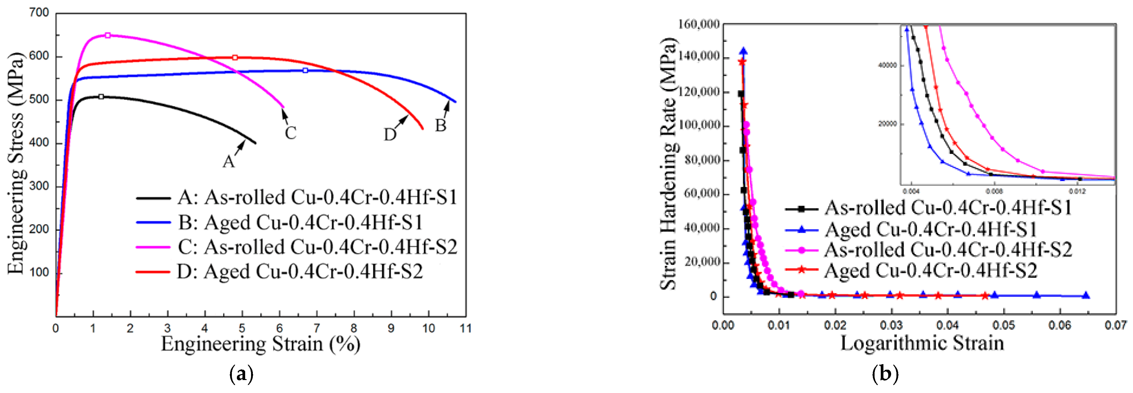
Figure 1. The process flow chart in this study.
Metals 12 00485 g001
Figure 2. Typical tensile curves of Cu-0.4Cr-0.2Hf-S1 and Cu-0.4Cr-0.4Hf-S1.
Metals 12 00485 g002
Figure 3. (a) Typical tensile curves of the as-rolled and aged Cu-0.4Cr-0.4Hf alloys; (b) strain hardening rate curves of the as-rolled and aged Cu-0.4Cr-0.4Hf alloys.
Metals 12 00485 g003
Figure 4. A longitudinal cross-section TEM observation of the aged Cu-0.4Cr-0.4Hf-S2. The inset shows the distribution of the deformation band width in the aged Cu-0.4Cr-0.4Hf-S2.
Metals 12 00485 g004
Figure 5. A high-magnification, longitudinal cross-section TEM observation of the aged Cu-0.4Cr-0.4Hf-S2.
Metals 12 00485 g005
Figure 6. (a) An HRTEM micrograph of aged Cu-0.4Cr-0.4Hf-S2 along the [001]Cu zone axis; (b) the corresponding FFT patterns of (a); (c) an HRTEM micrograph of aged Cu-0.4Cr-0.4Hf-S2 along the [011]Cu zone axis; (d) the corresponding FFT patterns of (c). Some precipitates are marked by ellipses in (a,c).
Metals 12 00485 g006
Figure 7. Combinations of ultimate tensile strength, uniform elongation and electrical conductivity in comparison with those of the previously reported copper alloys.
Metals 12 00485 g007
Table 1. Mechanical properties, electrical conductivity and dislocation density of Cu-0.4Cr-0.4Hf-S1 and Cu-0.4Cr-0.4Hf-S2.
Sampleσ0.2
(MPa)
σUTS
(MPa)
εu
(%)
εf
(%)
C
(%IACS)
ρ
(1014 m−2)
As-rolled Cu-0.4Cr-0.4Hf-S1497 ± 1508 ± 11.13 ± 0.135.31 ± 0.4433.85 ± 0.1213.84 ± 0.59
Aged Cu-0.4Cr-0.4Hf-S1540 ± 8565 ± 57.04 ± 0.5212.00 ± 0.9880.36 ± 0.135.86 ± 0.86
As-rolled Cu-0.4Cr-0.4Hf-S2621 ± 1644 ± 71.34 ± 0.095.47 ± 0.5562.25 ± 0.1329.24 ± 1.12
Aged Cu-0.4Cr-0.4Hf-S2566 ± 9593 ± 64.64 ± 0.209.54 ± 0.0480.51 ± 0.1813.50 ± 0.67
Publisher’s Note: MDPI stays neutral with regard to jurisdictional claims in published maps and institutional affiliations.

