Abstract
In the present paper, the medium-C Si-rich steel with a quenched martensite microstructure was heated to intercritical annealing temperatures at 750 °C, 760 °C and 770 °C after warm rolling deformation to obtain ferrite with varying volume fractions. Subsequently, bainite/ferrite multiphase microstructures were attained via austempering near Ms temperature. The microstructures of the test steel after different heat treatments were characterized by scanning electron microscopy, transmission electron microscopy and electron backscatter diffraction, and corresponding tensile and impact properties were tested. The results showed that, with the increase of intercritical annealing temperature, the austenite content increased, which limited the growth of ferrite grains, and the grain size decreased from ~1.6 μm to ~1.4 μm. In addition, the degree of ferrite recrystallization was almost complete. At the same intercritical annealing temperature, compared with austempering above Ms, prior athermal martensite (PAM) was obtained after austempering below Ms, which effectively refined the size of bainite ferrite lath. Moreover, with the increase of intercritical annealing temperature, the bainite content of the test steel increased after austempering, resulting in the increase of yield strength, tensile strength and impact energy. In contrast, while the decrease in ferrite content led to a significant decrease in uniform elongation. At constant intercritical annealing temperature, the tensile strength decreased slightly, and the impact property improved after austempering above Ms.
1. Introduction
As an important branch of high-strength low-alloy (HSLA) steel, dual-phase steels have been widely used in some industrial fields because of their excellent mechanical properties [1,2,3,4]. The traditional dual-phase steels are composed of a soft ferrite phase as the matrix and a small amount of hard martensite phase dispersed in the matrix, in which ferrite and martensite provide toughness and strength, respectively. Intercritical annealing is a common heat treatment method for preparing dual-phase steel, e.g., the test steel is heated to the α + γ phase region for partial austenitization to obtain a certain amount of austenite followed by a controlled cooling rate to make the austenite transform into martensite. In recent years, researchers have tried to use bainite with better toughness to replace martensite to form bainite/ferrite dual-phase steel. This approach has improved the toughness significantly at the expense of strength [5,6]. However, most relevant reports have used ferrite as the matrix in low-carbon steel to study the effect of introducing a small amount of martensite or bainite on the mechanical properties, while there have been few studies on introducing a large amount of bainite into medium carbon steel.
In the 1980s, Bhadeshia et al. [7,8,9,10,11] first obtained and defined the low-temperature bainite under isothermal transformation at a low-temperature condition of T = 0.25Tm (Tm is the absolute melting temperature) for several days in some high-carbon high-silicon steels. This low-temperature bainite microstructure was composed of ultra-fine bainite ferrite lath and thin-film retained austenite between laths, which had high strength and good toughness. Zhao et al. [12] studied low-temperature bainite microstructures by austempering around nose-tip temperature of the TTT diagram—the tensile strength of the material reached ~1550 MPa, attained ~30% uniform elongation and the impact toughness was 80 J. Zhao et al. [13] prepared a low-temperature bainite microstructure with a strength of 2223–2581 MPa in medium-carbon silicon-rich steel through ausrolling to reduce the Ms. Tian et al. [14] investigated the preparation of low-temperature bainite microstructures by austempering below Ms. The results showed that the best combinations of strength and ductility were obtained in steels by austempering below Ms with an optimum martensite fraction (∼5%). In addition to optimizing bainite, refining ferrite grain is also a key method to improve the properties of bainite/ferrite steel. Cold rolling or warm rolling with large deformation (>80%) and deformation-induced ferrite transformation (DIFT) are common methods to refine ferrite grains. For example, Mazaheri et al. [15,16] conducted 80% large deformation on the initial microstructure of ferrite and pearlite and heated it to different intercritical annealing temperatures to obtain ultrafine-grained ferrite with a size in the range of 1.6–3.8 μm. Xiong et al. [17] performed 40% deformation on austenite in low-carbon steel in the temperature range of 800–700 °C and obtained ~3 µm fine-grained ferrite by DIFT. Although the above methods have played a positive role in the refinement of ferrite, the operation is relatively difficult and needs to be accurately controlled in the preparation process.
In previous work, we have done some research on bainitic/ferritic dual-phase steels [18,19]. In this paper, a novel thermomechanical process for preparing an ultrafine-grained ferrite/low-temperature bainite microstructure was designed. The quenched martensite microstructure was subjected to intercritical annealing and austempering after 60% warm-rolling deformation, which was applied to medium-carbon Si-rich low-alloy steel, and different intercritical annealing temperatures were selected to obtain ferrite with different volume fractions (~30%, ~15% and ~5%). The effects of different heat treatment processes on the microstructure and mechanical properties (including tensile and notch impact toughness) were compared and analyzed.
2. Materials and Experimental Methods
The chemical composition of medium-C Si-rich steel used in this investigation is as follows: 0.47C-1.00Mn-1.61Si-0.20Mo-0.49Cr-0.001P-0.003S, balance is Fe, all in wt. %. The steels used in this study were smelted in a vacuum induction furnace and cast into ingots with a diameter of 180 mm. The ingot was homogenized at 1150 °C for 40 min, hot-rolled into a round bar with a diameter of 40 mm at the final rolling temperature of 850 °C and air-cooled to room temperature. Furthermore, the hot-rolled round bar was kept at 880 °C for 15 h and cooled to 400 °C in a furnace, followed by air cooling to room temperature for annealing.
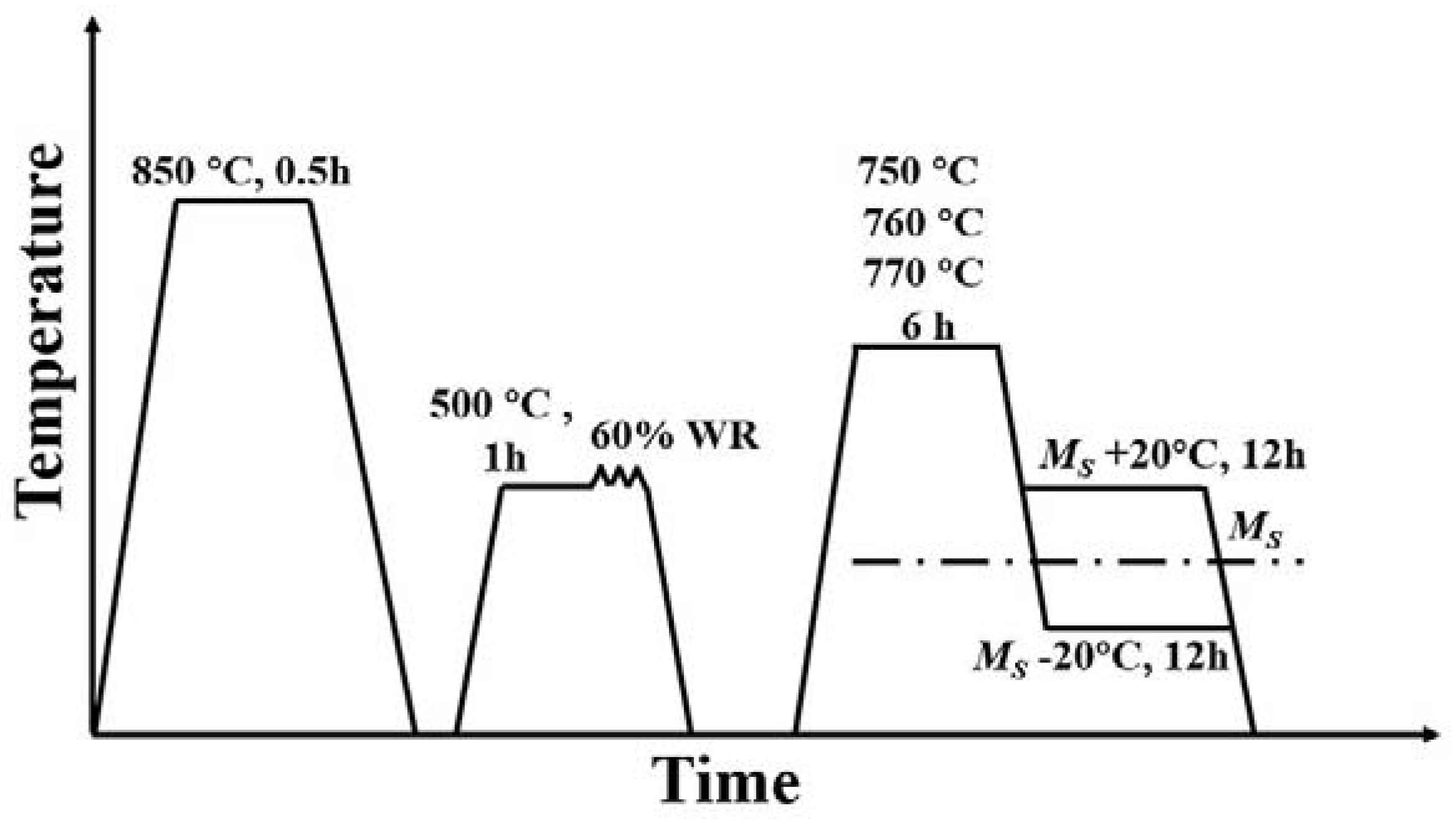
The annealed round bar was machined into rectangular samples with a thickness of 30 mm, a width of 20 mm and a length of 80 mm by wire cutting machine, and then subjected to the thermomechanical process, as shown in Figure 1. Firstly, the samples were heated to Ac3 + 40 °C and held for 30 min to attain full austenitization. Subsequently, the samples were quenched to room temperature to obtain martensite. The Ac3 temperatures determined by a dilatometer were 810 °C (Figure 2a). Secondly, the quenched samples were reheated to 500 °C and held for 1 h, followed by 60% warm-rolling deformation, and the final thickness of the sample was 12 mm. The warm rolling was completed in nine passes and the reduced amount of each pass was 2 mm. To ensure that the rolling temperature was maintained at 500 °C, the sample was kept at 500 °C for 2 min after every three rolling passes. Finally, the deformed samples were subjected to different temperatures at 750 °C, 760 °C and 770 °C for intercritical annealing. In order to achieve complete recrystallization of ferrite and complete dissolution of previously generated carbides, the holding time was finally determined to be 6 h through multiple experiments. Subsequently, the samples were immediately transferred to a salt bath furnace (potassium nitrate and sodium nitrite with a weight ratio of 1:1) for austempering. The austempering temperatures were selected as Ms ± 20 °C. The Ms temperatures after intercritical annealing at 750 °C, 760 °C and 770 °C were determined to be 210 °C, 250 °C and 270 °C, respectively, using a Gleeble-3800 thermomechanical simulator (Figure 2b). Therefore, the austempering temperatures corresponding to 750 °C were 190 °C and 230 °C, the austempering temperatures corresponding to 760 °C were 230 °C and 270 °C and the austempering temperatures corresponding to 770 °C were 250 °C and 290 °C, respectively. The holding times of all heat treatment processes were all 12 h.

Figure 1.
Schematic illustrations of the thermomechanical process.
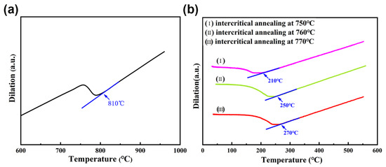
Figure 2.
(a) Dilation–temperature curves to measure the Ac3 temperature, (b) dilation–temperature curves to measure the Ms temperature after intercritical annealing.
The microstructures of the austempering samples were characterized by scanning electron microscopy (SEM) and transmission electron microscopy (TEM). The samples were etched with 4% nitric acid alcohol solution after grinding and polishing and the microstructures were observed by Hitachi SU-5000 SEM. TEM samples with a diameter of 3 mm were prepared by cutting 0.5 mm thick slices followed by mechanical grinding to ~30 μm in thickness and double-jet thinning to perforation at a voltage of 29 V. The electrolyte used was a solution of 7% perchloric acid in ethanol. The TEM characterization was completed using FEI Tolas F200X at an operating voltage of 200 kV. The electron backscatter diffraction (EBSD) analysis was conducted using a Hitachi SU-5000 equipped with EBSD equipment. The treatment of the EBSD sample was the same as that of the TEM sample. The acceleration voltage was 70 kV and the scan step was 0.1 μm for EBSD analysis. The volume of the retained austenite was measured by X-ray diffraction (XRD) using a Rigaku D/max-2500/PC diffractometer [20], with Cu-Kα radiation, the 2θ range was 40–105°, the scanning rate was 2 °/min and the working voltage and current were 40 kV and 200 mA, respectively.
Tensile samples with a gauge length of 25 mm, a width of 6 mm and a thickness of 4 mm were used for tensile tests on a MTS810 servo-hydraulic tensile tester, and the tensile speed was 3 mm/min. The impact toughness of the U-notched standard impact samples was tested by a 300 J Charpy impact machine. The size of the impact samples was 10 × 10 × 55 mm. The tensile and impact properties of samples in each state were tested three times to ensure the accuracy of the test results.
3. Results and Discussion
3.1. Microstructures
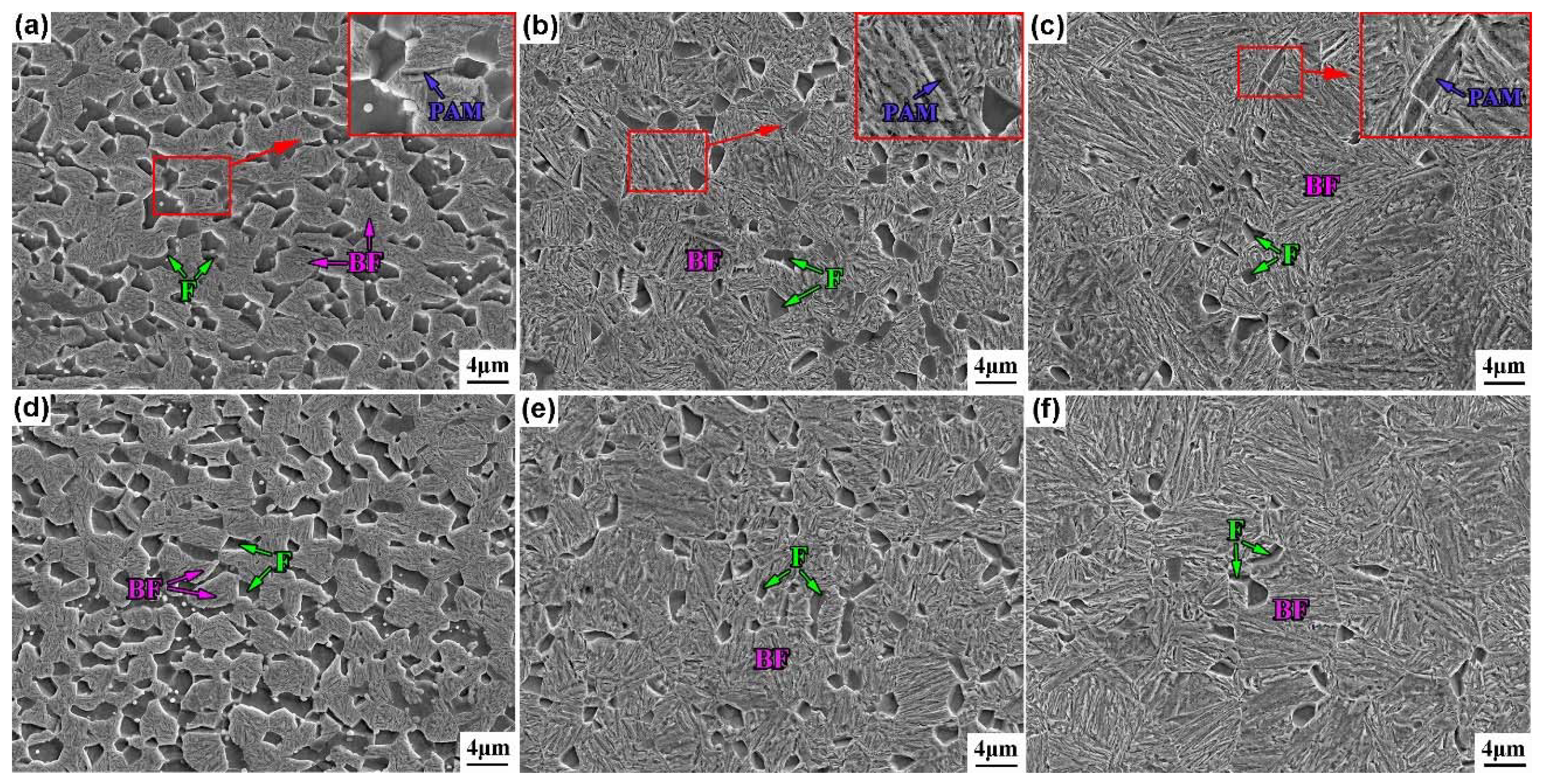
The SEM microstructures of the test steel austempered below and above Ms after intercritical annealing at different temperatures are shown in Figure 3. With the increase of intercritical annealing temperature, the content of ferrite in the test steel decreased obviously. The content of ferrite was determined by the statistic results of SEM microstructures. To ensure the accuracy and reliability of statistics, 20 SEM images in each state of the steel were counted. According to the statistic results, the content of ferrite reached ~30%, ~15% and ~5% after intercritical annealing at 750 °C, 760 °C and 770 °C, respectively. In addition, the ferrite grain sizes also decreased slightly to ~1.6 μm, ~1.4 μm and ~1.2 μm after intercritical annealing at 750 °C, 760 °C and 770 °C, respectively. This was due to increased austenite content at increased intercritical annealing temperature, limiting the growth of ferrite grain [21,22]. Moreover, the austenite grain size increased with the increase of intercritical annealing temperature. The average length of bainite ferrite laths increased, reaching ~8 μm, ~4.6 μm and ~10.5 μm after intercritical annealing at 750 °C, 760 °C and 770 °C, respectively. Furthermore, a certain amount of prior athermal martensite (PAM) was obtained after austempering below Ms, and it was tempered at subsequent holding, as exhibited in the locally enlarged diagrams in Figure 4a–c. The shape of PAM was irregular, and its size was significantly larger than that of the bainite ferrite lath.
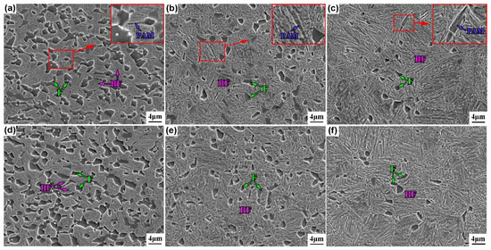
Figure 3.
SEM microstructures of the test steel at different heat treatment processes. (a): 750–190 °C, (b): 760–230 °C, (c): 770–250 °C, (d): 750–230 °C, (e): 760–270 °C, (f): 770–290 °C.
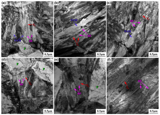
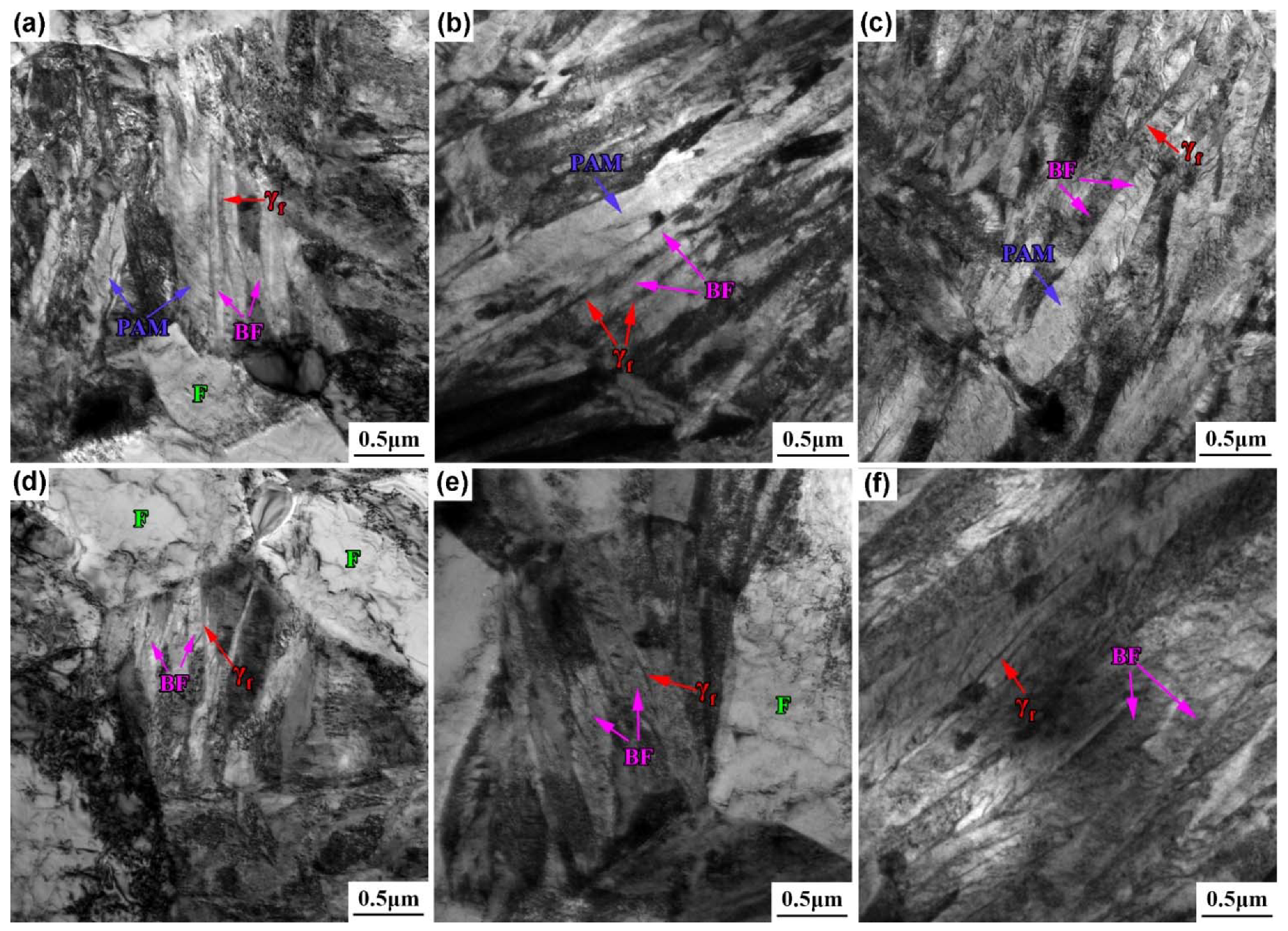
Figure 4.
TEM microstructures of the test steel at different heat treatment processes. (a): 750–190 °C, (b): 760–230 °C, (c): 770–270 °C, (d): 750–230 °C, (e): 760–270, (f): 770–290 °C.
Figure 4 displays the TEM microstructures of the test steel austempered below and above Ms after intercritical annealing at different temperatures. Many entangled dislocations existed in the polygonal ferrite and the bainite was composed of the bainite ferrite laths and the thin-film retained austenite between the laths. In addition, tempered martensitic microstructure, e.g., PAM, could be observed in the TEM images after austempering below Ms. The thickness tB of the bainite ferrite lath was obtained by measuring the average linear intercept LT perpendicular to the lath’s direction and crystallographic correction with the formula tB = 2LT/π [23], summarized in Table 1. The thickness of the bainite ferrite lath obtained after austempering below and above Ms was 74–123 nm and 112–165 nm, respectively. Many scholars have studied the reasons for refining bainite ferrite lath after austempering below Ms, which can be summarized as follows. Firstly, austempering below Ms has a greater undercooling when compared to austempering above Ms, which improved the nucleation rate and refined bainite laths [24,25,26]. Secondly, the PAM obtained after austempering below Ms divided the parent austenite grains into smaller parts, limiting the growth of bainite ferrite laths. Furthermore, martensite/austenite interfaces provided more nucleation sites for bainite formation, which further refined the bainite ferrite lath [26].

Table 1.
Thickness of bainite ferrite laths and content of retained austenite after different processes.
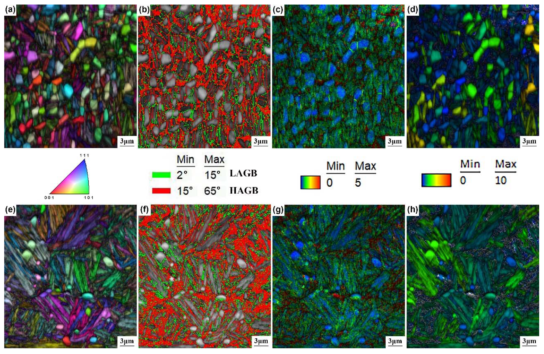
Figure 5 presents the image quality and inverse pole figure (IQ + IPF); grain boundary distribution, image quality and kernel average transportation (IQ + KAM); and image quality and grain orientation spread (IQ + GOS) diagrams of the test steel austempered above Ms after intercritical annealing at 760 °C and 770 °C. The red lines in the grain boundary distribution diagram represent the high-angle grain boundaries (15° ≤ HAGB ≤ 65°) and green lines represent the low-angle grain boundaries (2° ≤ LAGB ≤ 15°). The GOS demonstrates the average value of the difference between the average grain orientation and orientation of each nucleus in the grain. Lower GOS indicates lower grain orientation gradient, which connotes a smaller degree of lattice distortion. It can be seen from the IPF that the color inside the ferrite grains was basically the same, which illustrates that the orientation inside the grain was consistent, and there was no obvious distortion (Figure 5a,e). In addition, the interfaces in the microstructures were mainly HAGBs, while a few LAGBs existed at the ferrite grain boundaries and at the interfaces between ferrite and bainite ferrite (Figure 5b,f). For the KAM diagram, it could be observed that the strain concentration occurred at the interfaces between ferrite and bainite ferrite laths, and at the interfaces of bainite ferrite laths (Figure 5c,g). Moreover, for the GOS diagrams, the ferrite grains after intercritical annealing at 770 °C displayed a more blue color when compared to the ferrite grains after intercritical annealing at 760 °C, (Figure 5d,h), indicating an almost complete degree of recrystallization.
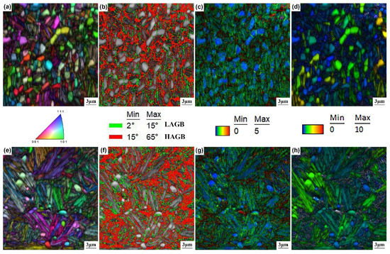
Figure 5.
(a,e) IQ + IPF, (b,f) grain boundary distribution, (c,g) IQ + KAM and (d,h) IQ + GOS diagrams of the test steel austempered above Ms after intercritical annealing at 760 °C and 770 °C.
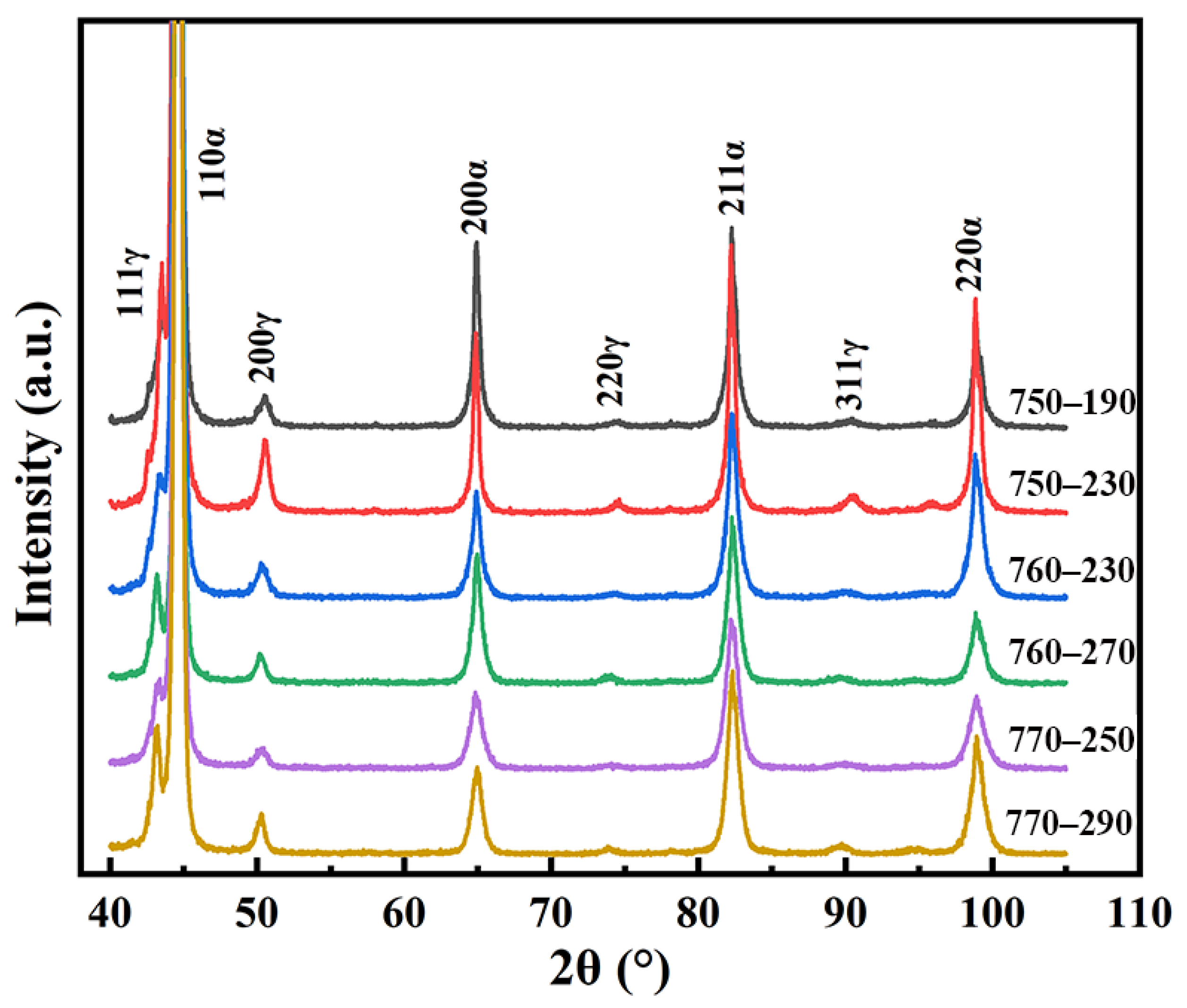
The XRD patterns of the test steel following different heat treatment processes are shown in Figure 6. BCC (ferrite) and FCC (austenite) phases were detected in all the samples. The corresponding constituents of retained austenite as calculated by the XRD diffraction peak are summarized in Table 1. When the intercritical annealing temperature increased from 750 °C to 770 °C, the retained austenite content decreased from 12.5–15.3% to 5.8–8.6%. As the intercritical annealing temperature increased, the corresponding austempering temperature increased and the time required for complete bainite transformation decreased. When the holding time (12 h) was the same, the higher the austempering temperature, the more complete the bainite transformation, resulting in a decrease of the retained austenite content. In addition, when the intercritical annealing temperature was constant, a small amount of PAM was preferentially obtained by below-Ms austempering, which accelerated the bainite transformation at the initial stage [25], making the bainite transformation more complete. Therefore, the retained austenite content below Ms was less.

Figure 6.
XRD patterns of the test steel following different heat treatment processes.
3.2. Mechanical Properties
3.2.1. Tensile Properties
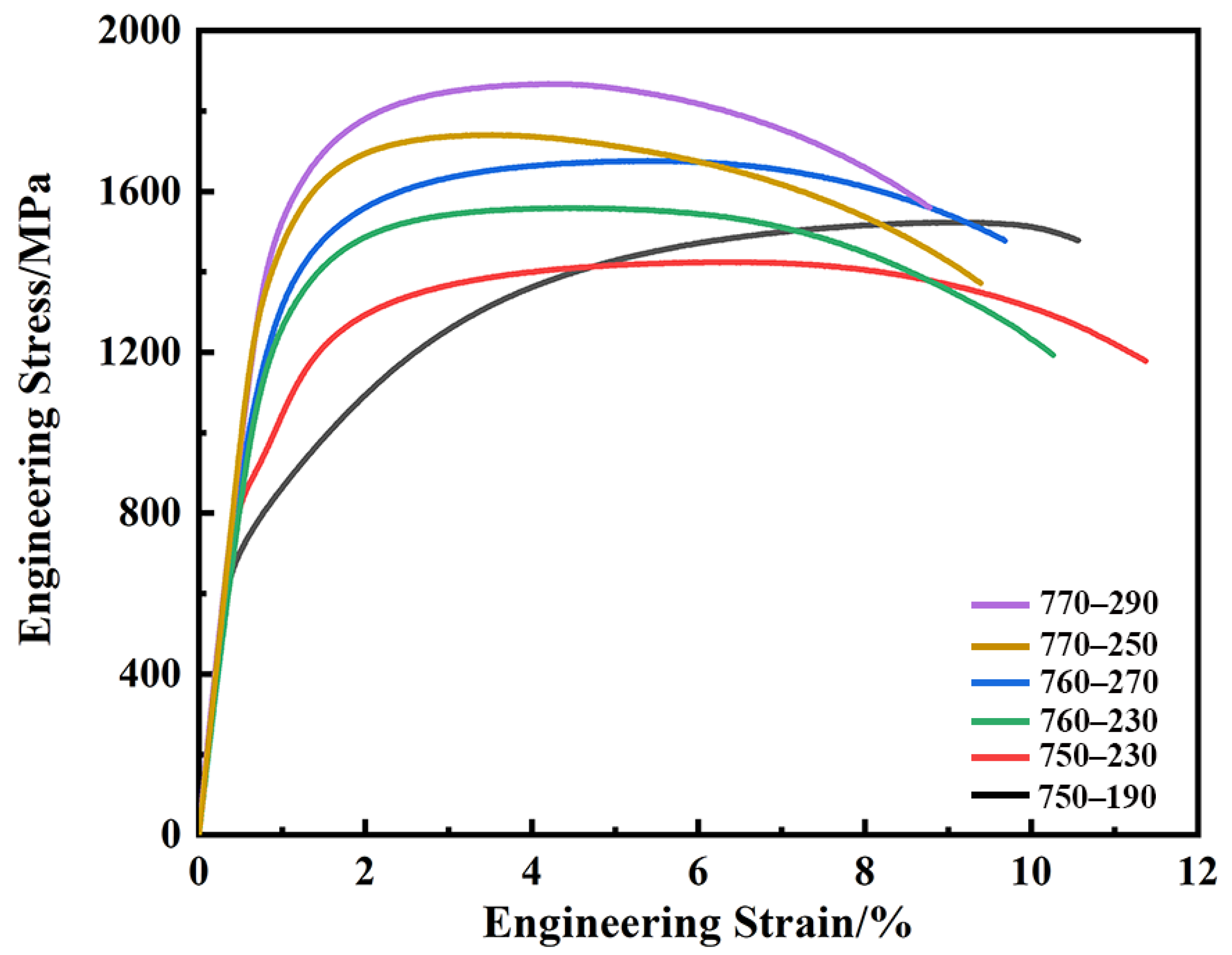
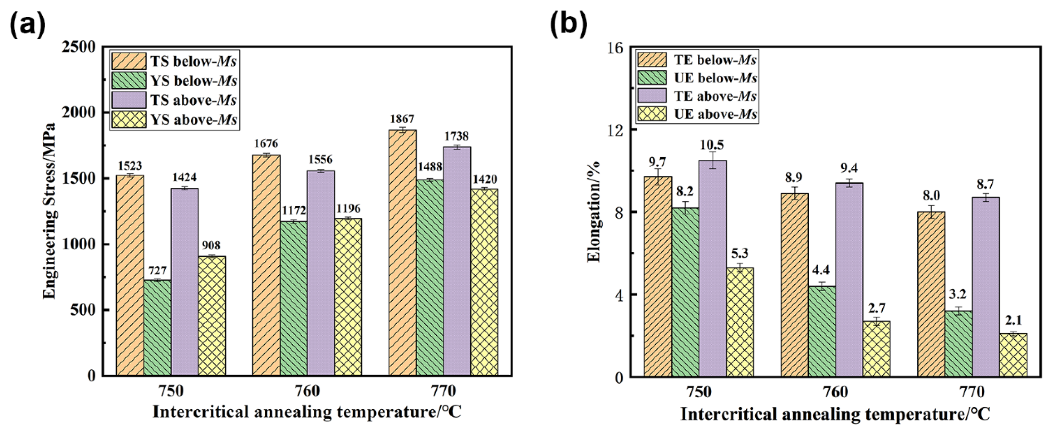
Figure 7 displays the tensile stress–strain curve of the test steel following different heat treatment processes. The specific tensile properties are shown in Figure 8. The tensile strength and yield strength increased as the intercritical annealing temperature increased. After intercritical annealing at 750 °C and austempering below and above Ms, the tensile strength attained 1523 MPa and 1424 MPa, and the yield strength was 727 MPa and 908 MPa, respectively. However, after intercritical annealing at 770 °C and austempering below and above Ms, the tensile strength increased to 1867 MPa and 1738 MPa, and the yield strength attained 1488 MPa and 1420 MPa, respectively. The difference in elongation after fracture of the test steel subjected to different heat treatment processes was not significant, which was in the range of 8.0–10.5%, but the difference in uniform elongation was significant. The uniform elongations reached 8.2% and 5.3% after intercritical annealing at 750 °C for austempering below and above Ms, respectively, but reduced to 3.2% and 2.1% after intercritical annealing at 770 °C and austempering below and above Ms, respectively. In addition, when the intercritical annealing temperature was constant, the tensile strength obtained after austempering below Ms was higher than that after austempering above Ms, and the uniform elongation decreased slightly.
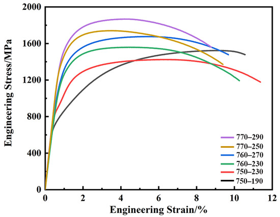
Figure 7.
Tensile stress–strain curves after different processes.

Figure 8.
(a) Tensile strength (TS), yield strength (YS), (b) total elongation (TE) and uniform elongation (UE) after different processes.
It can be deduced from the analysis of the microstructure and properties that as the intercritical annealing temperature increases, the bainite content increases, thus, increasing the yield strength and tensile strength, while the uniform elongation decreases significantly. During the tensile test of the samples, the soft ferrite phase preferentially deformed, dislocation density increased, work hardening occurred and the stress continued to increase. When the stress at the phase interfaces reached the yield stress of hard phases (bainite/martensite), the strain began to transfer from soft phases to hard phases [27]. With a further increase in deformation, the overall cumulative strain in the sample continued to increase until the sample necked and the stress decreased. After intercritical annealing at 750 °C, the content of the soft phase was more when compared to the intercritical annealing temperatures of 760 °C and 770 °C. The initiating time of strain transferring from soft to hard phase was delayed; thus, the uniform elongation improved. Moreover, when the intercritical annealing temperature was constant, compared with the austempering above Ms, PAM was obtained after austempering below Ms. Therefore, the strain was transferred from the soft phases to the multiple hard phases during tensile deformation, which increased the strain transfer process, resulting in a greater uniform elongation.
In addition, the TRIP effect provided by retained austenite also has a great influence on work hardening performance and uniform elongation [28,29,30,31]. It can be seen from the SEM and TEM images that the test steel mainly obtained stable film-like retained austenite after austempering, and no obvious block-retained austenite was observed, while the stable retained austenite extended the TRIP effect time to improve the uniform elongation. When relatively more retained austenite was obtained after intercritical annealing at 750 °C, the TRIP effect was more pronounced, resulting in higher uniform elongation. However, after intercritical annealing at 770 °C, the retained austenite was reduced and the uniform elongation was significantly decreased.
3.2.2. Impact Properties
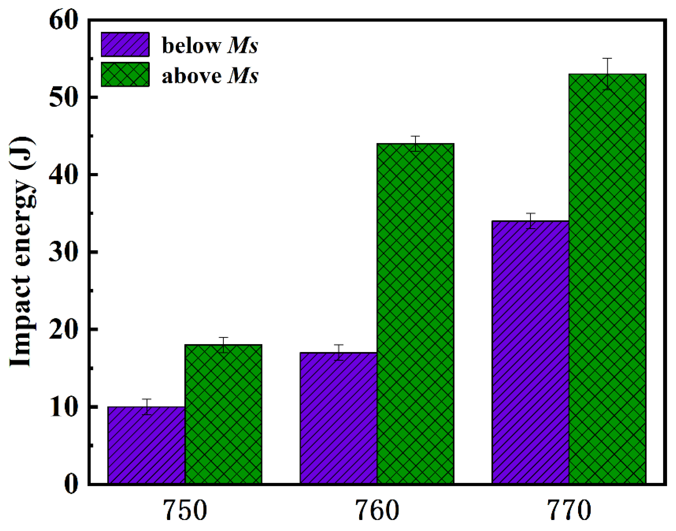
The impact energy of the test steel at different heat treatment processes is shown in Figure 9. The impact energy increased with the increase of intercritical annealing temperature. After intercritical annealing at 750 °C and austempering below and above Ms, the impact energy was 10 J and 18 J, respectively. When the intercritical annealing temperature increased to 770 °C, the impact energy value was enhanced to 34 J and 53 J after austempering below and above Ms, respectively. This indicates that the impact energy obtained after austempering above Ms was higher than that after austempering below Ms.
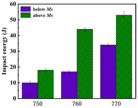
Figure 9.
Impact energy after different processes.
Bainite contributes more to the improvement of the impact energy when compared to ferrite. More austenite was obtained at increased intercritical annealing temperature and bainite content after austempering increased. Therefore, the maximum impact energy was obtained after intercritical annealing at 770 °C. Similar experimental results were reported by Gurumurthy et al. [32]. In addition, at constant intercritical annealing temperature, the impact energy of bainite ferrite increased with increasing austempering temperature, resulting in higher impact energy after austempering above Ms.
4. Conclusions
In the current study, ultrafine-grained ferrite/low-temperature bainite multiphase microstructure was obtained in the medium-C Si-rich steel through intercritical annealing followed by austempering heat treatment. Compared with the previous study, the process designed in this paper adopted a simple quenching + warm rolling treatment before intercritical annealing. Under the premise of not needing large deformation, the original microstructure was refined and the driving force for ferrite recrystallization was provided at the same time, achieving the purpose of refining ferrite. In addition, the holding time of the intercritical annealing had little effect on the size of ferrite, thus accurate control was not required in the actual production process. Subsequently, low-temperature bainite obtained by austempering ensured a considerable strength. The main results can be summarized as follows.
- (1)
- After intercritical annealing at 750 °C, 760 °C and 770 °C, the volume fractions of ferrite of ~30%, ~15% and ~5% were obtained, respectively. At increasing intercritical annealing temperatures, the average ferrite grain size decreased slightly to ~1.6 μm, ~1.4 μm and ~1.2 μm at 750 °C, 760 °C and 770 °C, respectively. The bainite ferrite laths were obtained after austempering below and above Ms, and a certain amount of prior athermal martensite (PAM) was obtained after austempering below Ms, resulting in a finer bainite ferrite lath.
- (2)
- The interfaces in microstructures obtained by different processes were mainly HAGBs, while a few LAGBs existed at the ferrite grain boundaries and at the interfaces between ferrite and bainite ferrite. There were obvious strain concentrations at the interfaces between ferrite and bainite ferrite laths, and at the interfaces of bainite ferrite laths. In addition, the degree of recrystallization in ferrite grains was almost complete at increasing intercritical annealing temperature.
- (3)
- With increasing intercritical annealing temperature, the bainite content increased, resulting in the increase in yield strength and tensile strength, while the uniform elongation decreased significantly. This was due to the formation of the soft ferrite phase at lower intercritical annealing temperatures. The initiating time of strain transferring from soft to hard phase was delayed; thus, the uniform elongation improved. In addition, the tensile strength decreased slightly and the impact property improved after austempering above Ms at the same intercritical annealing temperature when compared to austempering below Ms.
Author Contributions
Conceptualization, X.J., T.Z. and T.W.; methodology, L.W. and X.S.; formal analysis, X.J., T.Z. and L.W.; data curation, Y.W. and X.S.; writing—original draft preparation, X.J. and L.W.; writing—review and editing, Y.W. and T.W. All authors have read and agreed to the published version of the manuscript.
Funding
This work was supported by the National Natural Science Foundation of China (Grant No.51471147).
Institutional Review Board Statement
Not applicable.
Informed Consent Statement
Not applicable.
Data Availability Statement
The raw/processed data required to reproduce these findings cannot be shared at this time as the data also form part of an ongoing study.
Conflicts of Interest
The authors declare that they have no known competing financial interest or personal relationships that could have appeared to influence the work reported in this paper.
References
- Jiang, Z.H.; Guan, Z.Z.; Lian, J.S. Effects of microstructural variables on the deformation behavior of dual-phase steel. Mater. Sci. Eng. A 1995, 190, 55–64. [Google Scholar] [CrossRef]
- Sarwar, M.; Priestner, R. Influence of ferrite-martensite microstructural morphology on tensile properties of dual-phase steel. J. Mater. Sci. 1996, 31, 2091–2095. [Google Scholar] [CrossRef]
- Bouaziz, O.; Lung, T.; Kandel, M.; Lecomte, C. Physical modelling of microstructure and mechanical properties of dual-phase steel. J. Phys. IV 2001, 11, Pr4-223–Pr4-231. [Google Scholar] [CrossRef]
- Liedl, U.; Traint, S.; Werner, E.A. An unexpected feature of the stress–strain diagram of dual-phase steel. Comput. Mater. Sci. 2002, 25, 122–128. [Google Scholar] [CrossRef]
- Saeidi, N.; Ekrami, A. Comparison of mechanical properties of martensite/ferrite and bainite/ferrite dual phase 4340 steels. Mater. Sci. Eng. A 2009, 523, 125–129. [Google Scholar] [CrossRef]
- Bakhtiari, R.; Ekrami, A. The effect of bainite morphology on the mechanical properties of a high bainite dual phase (HBDP) steel. Mater. Sci. Eng. A 2009, 525, 159–165. [Google Scholar] [CrossRef]
- Garcia-Mateo, C.; Caballero, F.G.; Bhadeshia, H.K.D.H. Development of hard bainite. ISIJ Int. 2003, 43, 1238–1243. [Google Scholar] [CrossRef] [Green Version]
- Caballero, F.G.; Bhadeshia, H.K.D.H. Very strong bainite. Curr. Opin. Solid State Mater. Sci. 2004, 8, 251–257. [Google Scholar] [CrossRef] [Green Version]
- Caballero, F.G.; Bhadeshia, H.K.D.H.; Mawella, K.J.A.; Jones, D.G.; Brown, P. Very strong low temperature bainite. Mater. Sci. Technol. 2002, 18, 279–284. [Google Scholar] [CrossRef] [Green Version]
- Garcia-Mateo, C.; Caballero, F.G.; Bhadeshia, H.K.D.H. Mechanical Properties of Low-Temperature Bainite. Mater. Sci. Forum. 2005, 500–501, 495–502. [Google Scholar] [CrossRef] [Green Version]
- Garcia-Mateo, C.; Caballero, F.G.; Bhadeshia, H.K.D.H. Acceleration of low-temperature bainite. ISIJ Int. 2003, 43, 285–288. [Google Scholar] [CrossRef] [Green Version]
- Zhao, J.L.; Lv, B.; Zhang, F.C.; Yang, Z.N.; Qian, L.H.; Chen, C.; Long, X.Y. Effects of austempering temperature on bainitic microstructure and mechanical properties of a high-C high-Si steel. Mater. Sci. Eng. A 2019, 742, 179–189. [Google Scholar] [CrossRef]
- Zhao, J.; Guo, K.; He, Y.M.; Wang, Y.F.; Wang, T.S. Extremely high strength achievement in medium-C nanobainite steel. Scr. Mater. 2018, 152, 20–23. [Google Scholar] [CrossRef]
- Tian, J.Y.; Xu, G.; Hu, H.J.; Wang, X.; Zurob, H. Transformation kinetics of carbide-free bainitic steels during isothermal holding above and below MS. J. Mater. Res. Technol. 2020, 9, 13594–13606. [Google Scholar] [CrossRef]
- Mazaheri, Y.; Jahanara, A.H.; Sheikhi, M.; Kalashami, A.G. High strength-elongation balance in ultrafine grained ferrite-martensite dual phase steels developed by thermomechanical processing. Mater. Sci. Eng. A 2019, 761, 138021. [Google Scholar] [CrossRef]
- Jahanara, A.H.; Mazaheri, Y.; Sheikhi, M. Correlation of ferrite and martensite micromechanical behavior with mechanical properties of ultrafine grained dual phase steels. Mater. Sci. Eng. A 2019, 764, 138206. [Google Scholar] [CrossRef]
- Xiong, Z.P.; Saleh, A.A.; Kostryzhev, A.G.; Pereloma, E.V. Strain-induced ferrite formation and its effect on mechanical properties of a dual phase steel produced using laboratory simulated strip casting. J. Alloys Compd. 2017, 721, 291–306. [Google Scholar] [CrossRef] [Green Version]
- Zhao, T.; Jia, X.; Chen, C.; Zhang, F.C.; Wang, T.S. Simultaneously improved strength and impact toughness by introducing ultrafine ferrite in low-temperature bainitic steel. J. Mater. Res. Technol. 2021, 15, 5106–5113. [Google Scholar] [CrossRef]
- Jia, X.; Zhao, T.; Wang, L.; Sun, X.W.; Wang, Y.F.; Wang, T.S. Microstructure and Mechanical Properties of Low- and Medium-Carbon Si-Rich Low-Alloy Steels Processed by Austemping after Intercritical Annealing. Materials 2022, 15, 1178. [Google Scholar] [CrossRef]
- De, A.K.; Murdock, D.C.; Mataya, M.C.; Speer, J.G.; Matlock, D.K. Quantitative measurement of deformation-induced martensite in 304 stainless steel by X-ray diffraction. Scr. Mater. 2004, 50, 1445–1449. [Google Scholar] [CrossRef]
- Mazaheri, Y.; Kermanpur, A.; Najafizadeh, A. A novel route for development of ultrahigh strength dual phase steels. Mater. Sci. Eng. A 2014, 619, 1–11. [Google Scholar] [CrossRef]
- Huang, J.; Poole, W.J.; Militzer, M. Austenite formation during intercritical annealing. Metall. Mater. Trans. A 2004, 35, 3363–3375. [Google Scholar] [CrossRef]
- Chang, L.C.; Bhadeshia, H.K.D.H. Austenite films in bainitic microstructures. Mater. Sci. Technol. 1995, 11, 874–882. [Google Scholar] [CrossRef]
- Zhao, L.J.; Qian, L.H.; Meng, J.Y.; Zhou, Q.; Zhang, F.C. Below-Ms austempering to obtain refined bainitic structure and enhanced mechanical properties in low-C high-Si/Al steels. Scr. Mater. 2016, 112, 96–100. [Google Scholar] [CrossRef]
- Qian, L.H.; Li, Z.; Wang, T.L.; Li, D.D.; Zhang, F.C.; Meng, J.Y. Roles of pre-formed martensite in below-Ms bainite formation, microstructure, strain partitioning and impact absorption energies of low-carbon bainitic steel. J. Mater. Sci. Technol. 2022, 96, 69–84. [Google Scholar] [CrossRef]
- Navarro-Lopez, A.; Hidalgo, J.; Sietsma, J.; Santofimia, M.J. Influence of the prior athermal martensite on the mechanical response of advanced bainitic steel. Mater. Sci. Eng. A 2018, 735, 343–353. [Google Scholar] [CrossRef]
- Garcia-Mateo, C.; Caballero, F.G. Ultra-high-strength bainitic steels. ISIJ Int. 2005, 45, 1736–1740. [Google Scholar] [CrossRef] [Green Version]
- Chiang, J.; Lawrence, B.; Boyd, J.D.; Pilkey, A.K. Effect of microstructure on retained austenite stability and work hardening of TRIP steels. Mater. Sci. Eng. A 2011, 528, 4516–4521. [Google Scholar] [CrossRef]
- Mark, A.F.; Wang, X.; Essadiqi, E.; Embury, J.D.; Boyd, J.D. Development and characterisation of model TRIP steel microstructures. Mater. Sci. Eng. A 2013, 576, 108–117. [Google Scholar] [CrossRef]
- Pierman, A.P.; Bouaziz, O.; Pardoen, T.; Jacques, P.J.; Brassart, L. The influence of microstructure and composition on the plastic behaviour of dual-phase steels. Acta Mater. 2014, 73, 298–311. [Google Scholar] [CrossRef]
- Wang, T.L.; Qian, L.H.; Li, K.F.; Zhang FC Meng, J.Y. Strain-hardening behavior and mechanisms of a lamellar-structured low-alloy TRIP steel. Mater. Sci. Eng. A 2021, 819, 141498. [Google Scholar] [CrossRef]
- Gurumurthy, B.M.; Sharma, S.S.; Kini, A.; Mansoor, S. Effect of preheat treatment structure on mechanical characterization of AISI 4340 ferrite bainite dual phase steel. Mater. Today Proc. 2018, 9, 84–89. [Google Scholar]

Publisher’s Note: MDPI stays neutral with regard to jurisdictional claims in published maps and institutional affiliations. |
© 2022 by the authors. Licensee MDPI, Basel, Switzerland. This article is an open access article distributed under the terms and conditions of the Creative Commons Attribution (CC BY) license (https://creativecommons.org/licenses/by/4.0/).