Article

Structural Characterization of Ion Nitrided 316L Austenitic Stainless Steel: Influence of Treatment Temperature and Time

1
Division of Materials and Manufacturing Science, Graduate School of Engineering, Osaka University, 2-1, Yamadaoka, Osaka 565-0871, Japan
2
Faculty of Mechanical Engineering, Istanbul Technical University, Istanbul 34437, Turkey
*
Authors to whom correspondence should be addressed.
Metals 2022, 12(2), 306; https://doi.org/10.3390/met12020306
Submission received: 21 January 2022 / Revised: 7 February 2022 / Accepted: 8 February 2022 / Published: 10 February 2022
(This article belongs to the Special Issue Surface Engineering of Metals and Alloys)

Abstract

:
The ion nitriding behavior of AISI 316L austenite stainless steel was investigated at different nitriding times (2 h, 4 h, and 9 h) and temperatures (450 °C, 500 °C, and 550 °C). The structural characterization has been assessed by several considerations which can be listed: (i) the evaluation of phase distribution through Rietveld analysis of X-ray diffraction patterns and accompanying peak fitting process, (ii) hardness profile and related nitride layer thickness by microhardness and microscopic measurements, and (iii) displacement measurements to assess the residual stress accumulation. The diffusion of nitrogen atomic species into the sample surface caused a transformation of the γ phase matrix into an expanded austenite (γN) phase, which is recognized with its high hardness and wear resistance. Furthermore, depending on the nitriding condition, chromium nitride (Cr1-2N) and iron nitride (ε-Fe2-3N and γ′-Fe4N) phases were detected, which can be detrimental to the corrosion resistance of the 316L austenite stainless steel. The γN phase was observed in all nitriding conditions, resulting in a significant increase in the surface hardness. However, decomposition of the γN phase with an increase in nitriding temperature eventually altered the surface hardness distribution in the nitriding layer. Considering the phase-type and distribution with the consequent hardness characteristics in the nitride layer, to our best knowledge, this is the first report in which an ion-nitriding temperature of 500 °C (higher than 450 °C) and time of 9 h can be proposed as ideal processing parameters leading to optimal phase composition and hardness distribution for 316L austenite stainless steels particularly for the applications requiring a combination of both wear and corrosion resistance.

1. Introduction

Due to their excellent corrosion resistance, austenitic stainless steels are widely used in many industrial applications [1]. However, their surfaces can suffer from wear damages if they articulate on a counterpart surface, such as in dental implants, bone/joint replacements, etc. [2]. Therefore, an increase in their surface hardness and corresponding wear resistance without losing their corrosion resistance could significantly broaden their utilization in several different applications [3].
The surface hardness and wear resistance of steels, in general, can be improved with surface modifications, including coating processes, such as electrospraying and physical vapor deposition, etc. [4,5], or diffusion processes, such as carburizing, nitriding, etc. [6]. Nitriding is a well-established thermochemical process to increase the surface hardness of the steels, thus their wear and corrosion resistance. Among the nitriding processes, ion nitriding is recognized as a cost-effective and fast nitrogen diffusion process even at lower treatment temperatures and shorter times [7].
Additionally, if austenitic stainless steels, such as AISI 316L, are treated at the temperatures used in conventional nitriding treatments of steels (typically about 550 °C), they can suffer a significant decrease in their corrosion resistance due to the formation of chromium nitride precipitation with the expense of chromium in their solid solution, which would otherwise be used in the construction the protective film on their surfaces [8]. Therefore, their nitriding treatments are carried out at temperatures lower than 500 °C [9].
Upon ion nitriding process, a metastable phase consisting of supersaturated nitrogen atoms in the fcc austenite (γ) matrix can form in the nitride layer [10,11] in biomedical grade AISI 316L austenite stainless steel. This metastable phase, called expanded γ [8] or γN phase [12], can improve the surface hardness four to five times over γ matrix associated with an enhancement of the wear resistance in several orders of magnitude [6].
The characterization of the γN phase revealed that it can contain a high amount of nitrogen species (4 wt% to 14 wt% of N) in the form of solid solution before promoting precipitation of any other compound/s, such as Cr1-2N [13]. The characteristic peaks of the γN phase in the XRD pattern were expressed as shifted peaks of the γ matrix due to the expansion of γ lattice and the corresponding generation of the compressive stresses caused by the concentration gradient of diffusing nitrogen. Accordingly, the increase in surface hardness is due to the solute solution hardening mechanisms caused by this supersaturation of nitrogen species in the γN phase and the corresponding generation of compressive stresses in the nitriding layer [14].
In general, the overall structure of a nitriding layer can be separated into two overlying layers: (i) an underlying diffusion layer, and (ii) an outermost thin compound layer. Phase decompositions and formations of new phases occur in the diffusion layer. On the other hand, the formation of very hard and brittle ε and γ′ phases occurs in the compound layer.
It is proposed that the amount of the γN phase in the diffusion layer of AISI 316L stainless steels can be enhanced with increasing nitriding temperature and time promoting a richer and more homogenous distribution of nitrogen species and consequently increasing the thickness of the diffusion layer [7,8,9,12]. However, there is a critical value for nitriding temperature and time, and upon exceeding these critical values, a decomposition of the γN phase into α-ferrite and CrN can occur [15], which can further increase the surface hardness, while resulting in a detrimental loss in its corrosion resistance.
The compound layer, consisting of iron nitrides (ε-Fe2-3N, γ′-Fe4N), is quite hard and brittle. The thickness of this compound layer depends on the nitriding parameters. For instance, an increase in temperature can result in a decrease in the thickness of this layer due to denitriding, thus decreasing the overall surface hardness [7].
The denitriding in the form of decomposition of the γN phase, and consequent precipitation of the CrN phase, can alter the surface characteristics of AISI 316L, leading to a decrease in the surface hardness and consequent deterioration of the wear and corrosion resistance. The vast majority of the studies in the literature on nitrided stainless steel have focused, in general, only the formation of the γN phase emphasizing its increasing effect on the hardness and corrosion resistance, and the formation of CrN emphasizing its detrimental effect on wear and corrosion properties [6].
For this reason, a deeper understanding of the effect of process parameters on the nitride layer characteristics is of great importance to evaluate the overall hardness and indirectly the wear and corrosion properties of the AISI 316L austenite stainless steel. Thus, the purpose of this study is to investigate the effect of ion nitriding temperature and time, on its surface structural characteristics with the characterization of the existing phases, nitriding layer thicknesses, and corresponding hardness and their distributions in the nitride layer.

2. Materials and Methods

The AISI 316L austenite stainless steel samples used in this study were cut from cylindrical bars with a diameter of 8 mm and a thickness of 15 mm. The chemical composition of the steel is shown in Table 1. The cylindrical AISI 316L samples were ground and mechanically polished to a mirror surface to guarantee a regular and flat surface for the nitriding process. Additionally, the nitriding surfaces were cleaned by trichloroethylene from any oil and dust before the nitriding treatment.
A custom-made DC plasma ion nitriding equipment was used to carry out nitriding treatment. A high silica tube, 200 mm in diameter and 400 mm in height, was used as the nitriding chamber [16]. The cathode was placed in the middle of the chamber. A 30 mm in diameter stainless steel disc which was positioned to the middle of the chamber was used as a cathode. The samples were placed onto this cathode plate. A disc-shaped metal plate with 130 mm in diameter and 2.5 mm in thickness was used as an anode. A thermocouple was connected to the sample through the cathode to monitor the treatment temperature.
The tube was first evacuated to 10 Torr with a single-stage rotary vacuum pump that maintained vacuum pressure. The same vacuum pump was also used to maintain the desired vacuum level throughout the nitriding processes.
Before the plasma nitriding, the samples were subjected to cleaning by hydrogen sputtering for 30 min to remove surface oxides and other contaminates. Then, the plasma nitriding was performed in a gas mixture of 80%N2–20%H2, with a total pressure of 1 kPa. The nitriding temperatures were 450 °C, 500 °C, and 550 °C; the treatment times were 2 h, 4 h, and 9 h.
The phases of the nitrided layers were analyzed by X-ray Diffraction (XRD, Panalytical X’pert, PW3040, Malvern Panalytical Ltd, Malvern City, UK). Cu-Kα radiation (λ = 1.5406 nm) produced at 45 kV and 40 mA scanned the diffraction angles (2θ) between 35° and 55° at every 0.145° for 1 s. Diffraction signal intensity throughout the scan was monitored and processed with X-Pert HighScore Plus software 3.0 (Malvern Panalytical Ltd) performing Rietveld analysis; furthermore, the peak identification was conducted by open-source peak fitting software (PeakFit 4.1.2).
The nitriding layer was observed from the cross-section of nitride samples by optical microscopy (OM, Nikon, Eclipse LV150, Tokyo, Japan) and selective electron microscopy (SEM, Cameca SX 100, CAMECA, Gennevilliers, France). Vickers microhardness (HV) tests were performed on the cross-sections of the nitride samples using a Shimadzu Micro Hardness Tester (HMV-G31S, Shimadzu, Kyoto, Japan). The indentation load was 100 g and the indentation time was 10 s.
To evaluate the residual stress in the nitriding layer, micrometer measurements were conducted on the nitriding surface before and after wire cutting. To be able to observe the stress accumulation during nitriding, 3 steps of micrometer measurements from the center of the nitride surface were carried out and the difference of the measured values after wire cutting (stress-release) was discussed as residual-stress-induced displacement.

3. Results and Discussion

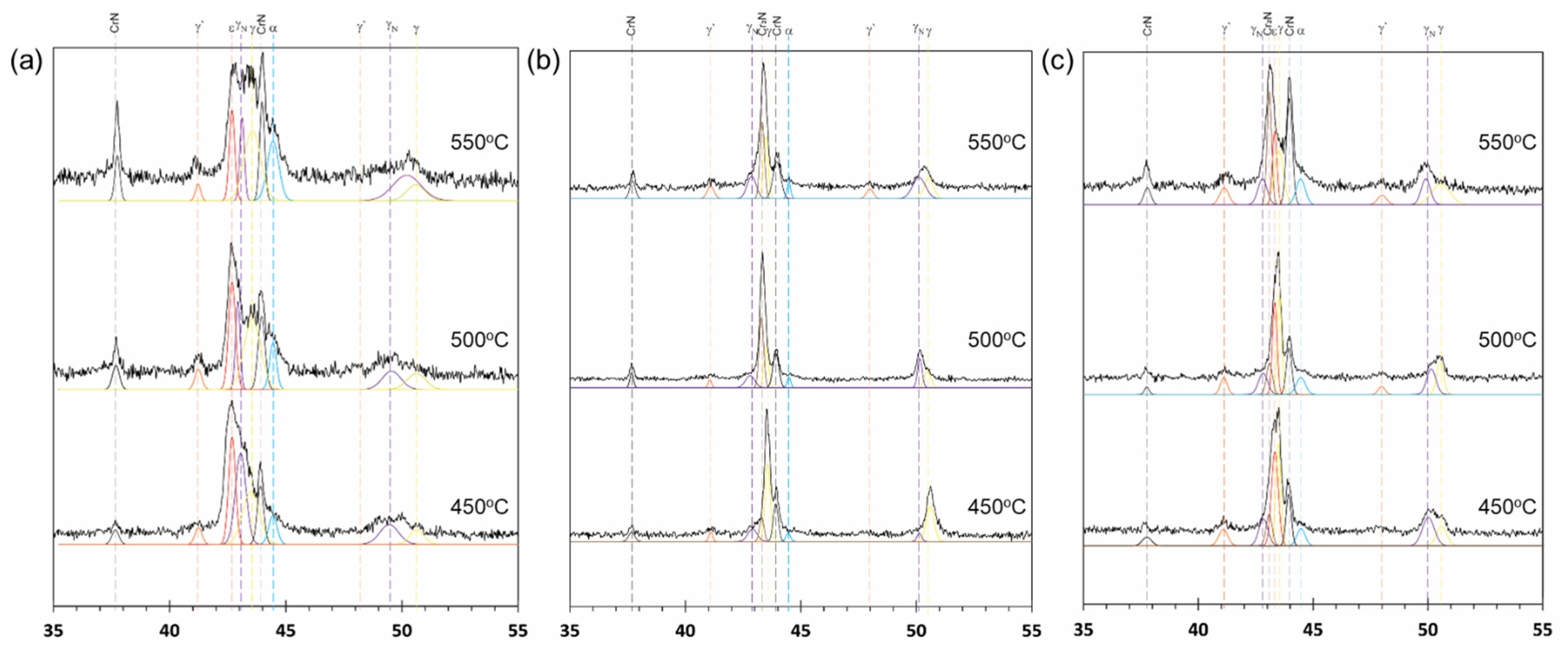
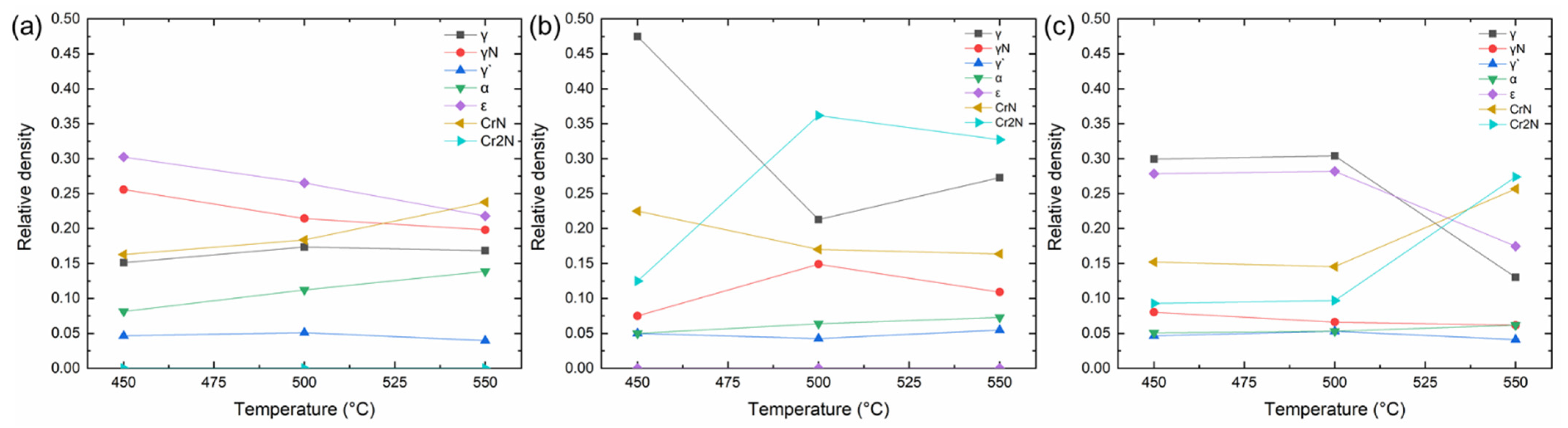
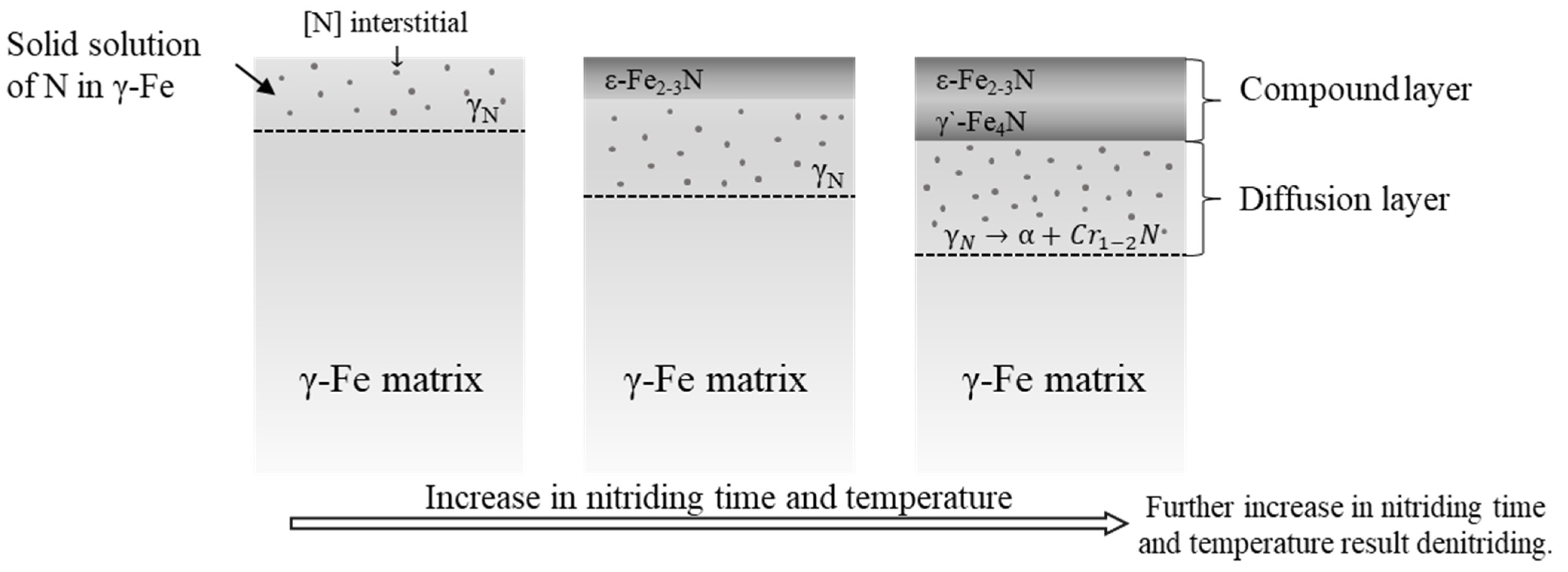
3.1. Phase Formation Characteristics

XRD patterns of the nitride layers on AISI 316L samples obtained at different nitriding temperatures and times are given in Figure 1. γ, γN, γ′, α, ε, CrN, and/or Cr2N are the major and minor phases detected in all patterns. The existence of the γN phase was detected from the peaks formed by shifting the peaks of the matrix γ phase to a smaller diffraction angle [6] due to the nitrogen penetration into its lattice structure. The presence of the γN phase formed by the diffused nitrogen into the γ phase is crucial as it plays a critical role to obtain a combination of high hardness and good corrosion properties [17]. Therefore, the existence of metastable γN phase even after 2 h nitriding was evidence of a successful surface modification in this study (Figure 1a).
The relative amounts of the phases detected in the nitride layer observed upon treatment for (a) 2 h, (b) 4 h, and (c) 9 h at 450, 500, and 550 °C are given in Figure 2 based on those given in Figure 1. The γ, γN, γ′, α, ε, CrN, and Cr2N phases were observed at 450 °C for 2 h in Figure 2a. As the temperature increased, the amount of the ε and γN phases showed a continuous decrease, while those of the α and CrN phases showed an increase. On the other hand, the amount of γ′ and γ phases remained almost constant. No considerable amount of the Cr2N phase was detected.
Upon nitriding for 4 h at 450 °C (Figure 2b) the relative amount of γ phase showed a decrease at 500 °C and slightly increased at 550 °C. The Cr2N phase became apparent at 450 °C. Then, its amount first showed an increase at 500 °C and then slightly decreased at 550 °C. Likewise, the amount of the γN phase first showed an increase at 500 °C and slightly decreased at 550 °C. Although those of α and γ’ phases were lower than others, their amount showed a slight increase. The ε phase was not detected in these processing conditions.
Upon nitriding for 9 h (Figure 2c), all phases became apparent in the respected XRD patterns. Their relative amounts, interestingly, did not show a considerable change upon processing at 450 °C and 500 °C. On the other hand, the amount of the γ and ε phases showed a considerable decrease at 550 °C, while CrN and Cr2N phases showed a considerable increase and became dominant phases. The amount of the γN, γ’, and α phases was relatively low compared to others and even they did not show a considerable change compared to others. Nevertheless, it should be stated that the γN and γ’ phases slightly decreased at 550 °C, while the α phase remained almost constant.
As a general trend, when the nitriding temperature was increased from 450 °C to 500 °C, the amount of peak shift was increased for all nitriding times, most probably as a response to increasing nitrogen concentration. It has been reported that the nitrogen interstitial concentration in the γN phase can reach 14 wt% [8]. However, when the nitriding temperature was further increased to 550 °C, the related peaks started to shift back as an indication of a decrease in the amount of the γN phase and an increase in that of the γ phase, as clearly observed in Figure 2b. This event can be attributed to the denitriding of the γN phase due to relatively high treatment temperature [14].
On the other hand, the decrease in the amount of the γN phase was not always counterbalanced by an increase in the γ phase alone. For instance, there was also an increase in the relative amounts of the CrN and the α phases. This event can also be attributed to the denitriding of the γN phase [14]. During this denitriding process, the γN phase can decompose and release chromium and nitrogen species, leading to the precipitation of the CrN phase and the formation of the α phase (γN → α + CrN), as shown in Figure 2a. It should be emphasized that the CrN formation was favored due to the high negative enthalpy and low Cr diffusivity (high diffusion activation energy) in the matrix phase at temperatures higher than 450 °C [13,18].
Furthermore, although Cr2N was not observed upon treatment for 2 h, a significant amount of the Cr2N phase became apparent at 4 h (Figure 1b and Figure 2b) associated with the appearance of the CrN phase. Therefore, it may be proposed that the denitriding of the γN phase may also promote the formation of the Cr2N phases as such a mechanism that γN → α + Cr2N. This may definitely cause a further decrease in corrosion resistance due to the increasing consumption of Cr species.
Nevertheless, it can be deduced that upon nitriding for 9 h, the γN phase exhibited a more stable behavior, assuming that the balance between nitrogen diffusion and denitriding mechanisms was established.
Moreover, the decrease in the amount of the ε phase with increasing temperature (Figure 2a,c), can also be attributed to the denitriding mechanism [19]. On the other hand, the formation of the γ′ phase seems to be due to the transformation of the γN phase due to the increasing concentration of nitrogen species. However, its relative amount did not considerably change in different processing conditions.
In this regard, a typical evaluation of nitride layer structure on 316L stainless steel is schematically proposed in Figure 3. It can be expected that the layer in which the γN phase existed and its decomposition into the CrN, Cr2N, and α phases occurred is the diffusion layer. On the other hand, the layer consisting of the ε and γ‘ phases can be considered as the compound layer.
The high amount of the ε phase in the compound layer is expected to demonstrate a hard and brittle layer at nitriding temperatures of 450 °C and 500 °C. The detection of ε phase after 9 h nitriding indicated that the penetration depth of ε phase reached a value wherein denitriding was insufficient to decompose ε phase at nitriding temperatures of 450 °C and 500 °C. However, a drastic decrease in ε phase and the consequent increase in CrN and Cr2N precipitations can be correlated with the denitriding of ε phase and decomposition of γN phase at 550 °C nitriding temperature.
Considering the variation of nitriding temperature and time, γ′ phase showed a stable amount for each nitriding condition. Therefore, the fluctuation in hardness was expected to be due to the variations in the amounts of γN, ε, and α phases associated with the CrN and Cr2N precipitations.

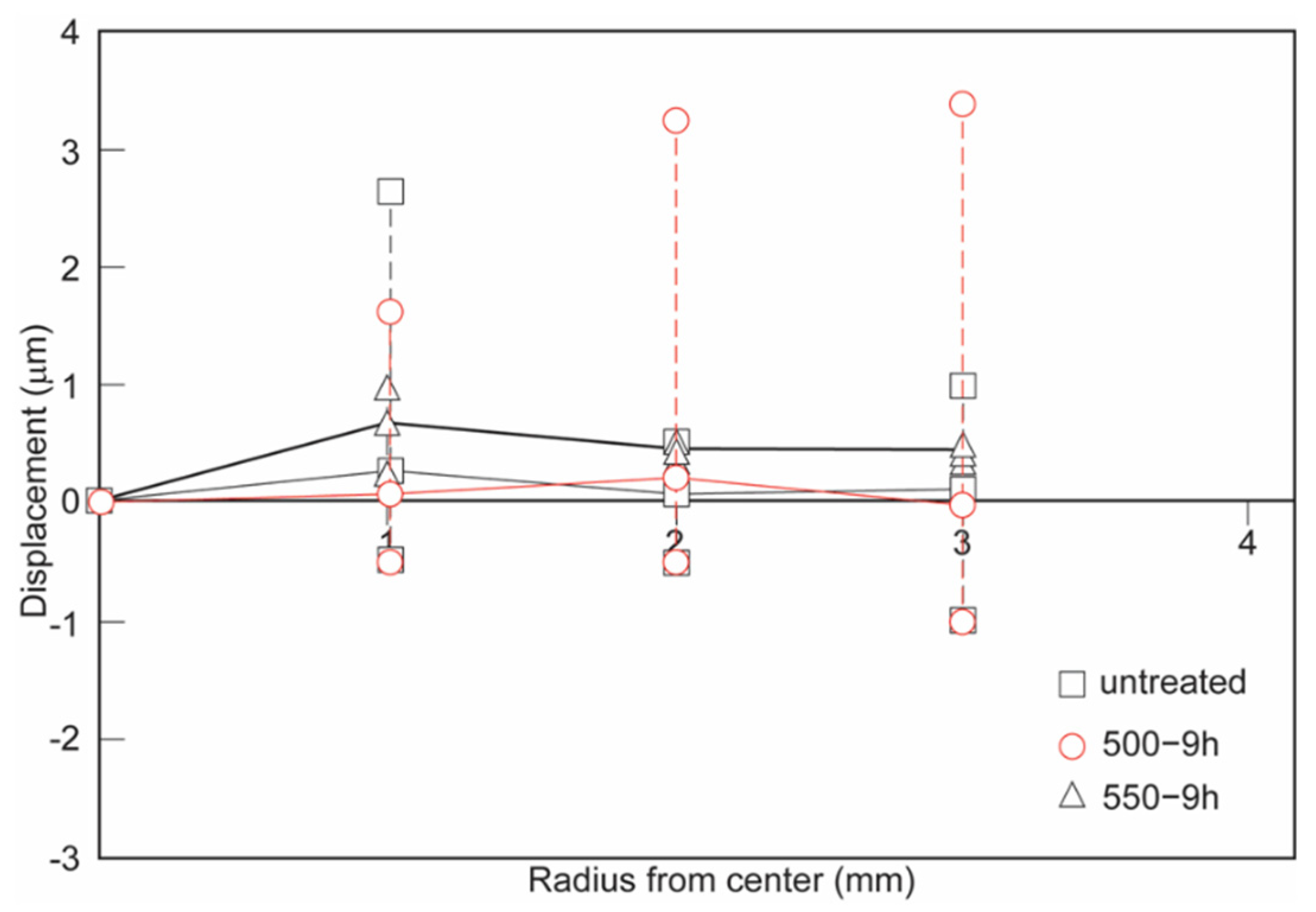
3.2. Measurements of Residual-Stress-Induced Displacements

To investigate the effect of the accumulated stress on the nitriding layer, displacement measurements were conducted on 316L samples nitrided at 500 °C and 550 °C for 9 h and after stress-release (wire cutting). The displacement results were presented in Figure 4 with corresponding highest and lowest measurements compared to untreated samples. While untreated samples showed near-neutral displacement similar to treated samples, the increasing tendency in the highest and lowest displacement of treated samples indicated the accumulated residual stress which can be beneficial to improve surface hardness, wear, and corrosion resistance [19].
The nitrogen penetration to the matrix γ phase forming expanded γN phase and intensive phase transformations during the nitriding process are expected to cause compressive residual stress in the nitriding layer. It has been reported that the expanded γN phase in the nitride layer exhibited peak broadening due to the gradient of nitrogen and accumulated residual stresses [19]. To this extent, 316L sample nitrided at 500 °C for 9 h was expected to present high hardness with sufficient nitrogen diffusion which resulted from high residual-stress-induced displacement, however, the samples nitride at 550 °C demonstrated no accumulated stress owing to stress relaxation by high-temperature nitriding.

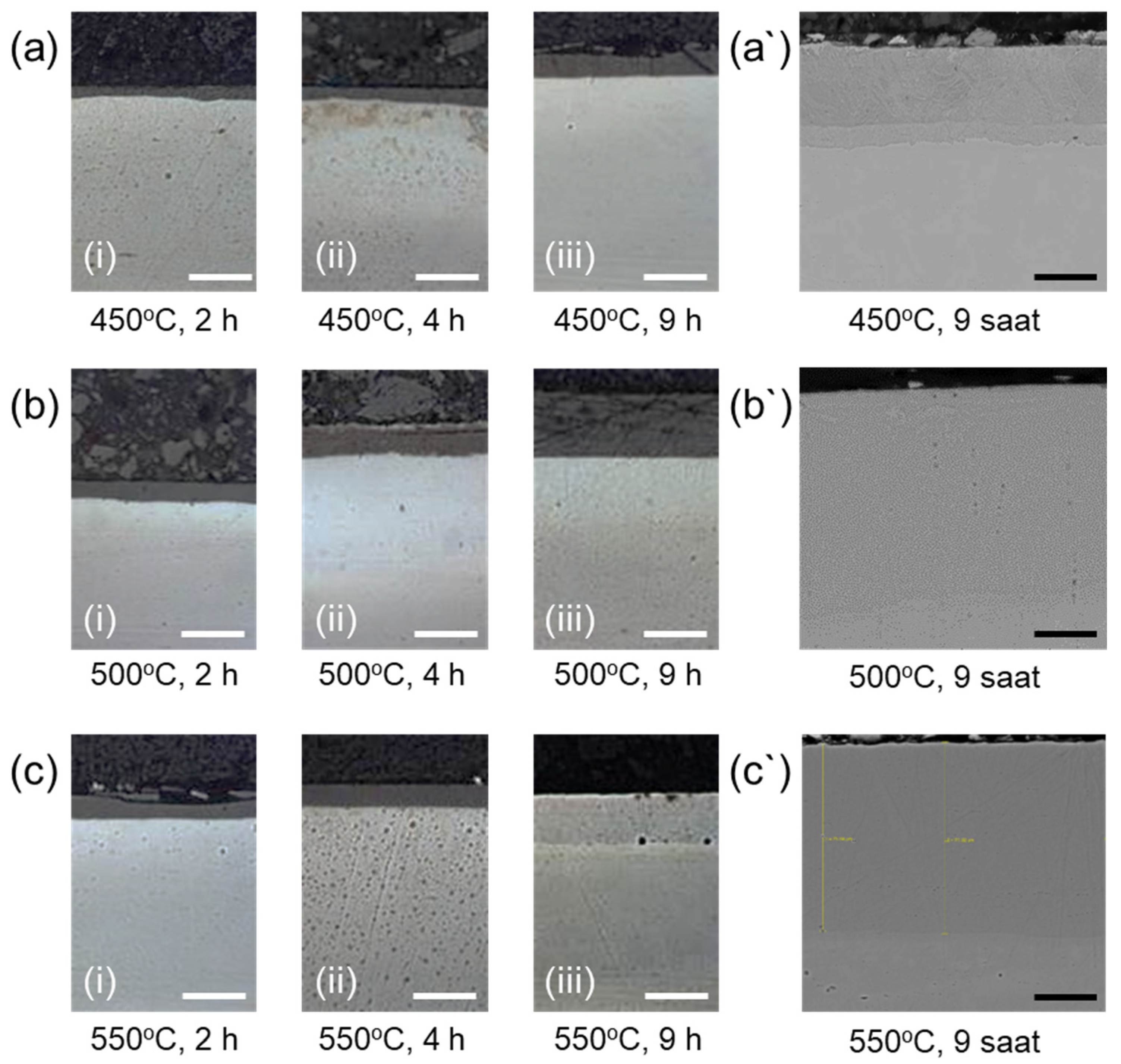
3.3. Microhardness and Microstructural Analysis

Vickers microhardness measurements were carried out on the cross-section of nitride samples to clarify the nitride layer thickness. The results of cross-sectional microhardness measurements of samples nitrided for 2 h, 4 h, and 9 h at 450 °C, 500 °C, and 550 °C were presented in Figure 5 according to the distance from the surface.
Upon nitriding for 2 h, the surface hardness increased from about 900 HV to 2000 HV when the nitriding temperature was increased from 450 °C to 500 °C. However, the surface hardness decreased to about 1300 HV when the nitriding temperature was further increased to 550 °C (Figure 5a). With a similar trend, upon nitriding for 4 h, the surface hardness increased from about 900 HV to 1900 HV when the nitriding temperature was increased from 450 °C to 500 °C, and then decreased to about 1400 HV at 550 °C (Figure 5b).
More interestingly, upon nitriding for 9 h, the surface hardness was decreased from 2100 HV to 1500 HV when the nitriding temperature was increased from 450 °C to 500 °C, and then further decreased to 1400 HV at 550 °C (Figure 5c).
OM images of nitriding cross-sections were demonstrated the nitride layer as a darker region due to the nitrogen penetration and consequent phase transformations (Figure 6a–c). Although some delamination of the outer nitride layer was observed due to the formation of brittle ε phase as seen in Figure 6a(iii), SEM images presented a defect-free nitride depth (Figure 6a′–c′), reaching 95 µm after 9 h nitriding at 500 °C (Figure 6b′).
The nitride layer thickness was evidently observed by OM and SEM measurements as shown in Figure 6, corresponding to the results of microhardness measurements. Considering the results obtained by the hardness-depth profiles determined by microhardness measurements, OM, and SEM micrographs, the approximate nitride layer thicknesses for each nitriding condition are about 15, 40, and 45 µm for 450, 500, and 550 °C, respectively, as listed in Table 2.
It is not surprising that the increase in nitriding time and temperature results in an increase in nitriding layer thickness [7,9,20]. However, the aforementioned differences in the relative amount of the phases are critically important to understand the hardness levels and distributions in the depth profiles. The hardness of the matrix of untreated samples was about 330 HV. On the other hand, the hardness of the γN phase is able to reach over 1200 HV depending on the amount of diffused nitrogen in its structure [21]. Moreover, γ′, ε, and α phases, as such CrN and Cr2N precipitates, can reach hardness around 2000 HV [18]. Therefore, the fluctuations in microhardness measurements can be attributed to the distribution of brittle phases (γ′ and ε in compound layer) and nitrides (Cr1-2N in diffusion layer) in the nitride layers.
Upon nitriding for 2 h, the highest hardness was detected from the sample nitrided at 500 °C. According to our findings based on Figure 1a and Figure 2a, the samples nitrided at 450 °C have a higher amount of α phase and CrN, and lower amount of γN and ε phases compared to the ones nitrided either at 500 °C and 550 °C. On the other hand, a possible denitriding process was detected in the γN and ε phases in the samples nitrided at 550 °C. Therefore, it is not surprising that the sample nitrided at 500 °C has the highest hardness with a value of almost 2000 HV (Figure 5a) with its sufficiently thick nitride layer (about 40 µm) composed with a compound layer consisting of hard and brittle γ’ and ε phases.
The samples nitrided for 4 h showed the same dependency on nitriding temperature in the hardness-depth profiles, as shown in Figure 5b. However, the lower hardness of sample nitrided for 4 h with a value of 1825 HV compared to one nitrided for 2 h with a value of 2015 HV for the nitriding temperature at 500 °C can be attributed to denitriding of ε phase at the outermost layer as discussed in Section 3.1.
Despite the increase in nitriding time from 2 h to 4 h for 450 °C nitriding temperature, the characteristics of hardness were similar (Figure 5a,b), exhibiting approximately the same nitride layer thickness (15 µm as expressed in Table 2). Thus, it is assumed that an increase in nitriding time from 2 h to 4 h merely affected the phase distribution regarding denitriding (Figure 1a,b). As such, in exchange for denitriding of ε phase, Cr2N was formed for hardening nitriding layer.
Interestingly, the hardness of the sample nitrided at 450 °C was the highest among the samples nitrided for 9 h, reaching over 2000 HV (Figure 5c). It can be anticipated that the erratic alterations in hardness depth profile up to about 10 µm depth can be in parallel to the inhomogeneous and nonlinear distribution gradient of the ε phase in the compound layer. In this regard, considering the overall nitride layer thickness as about 50 µm, the rest 40 µm is expected to be the diffusion layer composed of the γN, α phases, and nitride precipitates for sample nitrided at 450 °C for 9 h. Therefore, the fluctuation in hardness in this diffusion layer can be attributed to the corresponding distributions of nitride precipitates.
On the other hand, the decrease in near-surface hardness of samples nitrided at 500 and 550 °C for 9 h indicated denitriding of outer ε phase (Figure 5c), while a significant decrease in ε phase density was clarified (Figure 2c). It is worth mentioning that denitriding of the ε phase might enhance the quality of the nitride layer while preventing delamination, as observed in Figure 6a(iii),b(iii),c(iii),a′,b′,c′.
Previous reports recommended 450 °C nitriding temperature to reach maximum surface hardness, and accordingly good wear and corrosion-resistance [22,23], which was expected as a very valuable outcome of a more stable γN phase. Similarly, observation of the highest hardness in the sample nitrided at 450 °C for 9 h with its the highest relative amount of the γN phase is in very good agreement with the literature [17,20,24,25]. However, it should be noted that the existence of ε phase in the compound layer upon nitriding at 450 °C can cause undesirable consequences, such as high brittleness and delamination in the surface layers.
On the other hand, although it has been reported that CrN precipitation showed no detrimental effect on wear and corrosion in a low relative density [9], increasing nitriding temperature to 550 °C will promote the precipitation of increasing the amount of Cr1-2N phases, ultimately consuming a substantial amount of free chromium available to construct a surface oxide layer important for corrosion protection. Consequently, the corrosion resistance of the samples can undesirably be deteriorated [26] with increasing nitriding temperature.
Therefore, according to the results of this study of interest, it can be proposed that a nitriding temperature of 500 °C can present an ideal combination of high hardness and hardness depth profile, providing an ideal solution for the applications requiring wear as well as corrosion resistance.

4. Conclusions

This study investigated the microstructural characteristics of ion-nitrided biomedical grade AISI 316L stainless steel considering the influence of nitriding time and temperature. The following conclusions can be withdrawn from the above results:
  • The γN phase existed in the diffusion layer in all different nitriding conditions. This phase was responsible for the hardness increase upon the ion nitriding process.
  • The compound layer thickness consisting of hard and brittle ε phase increased significantly at 9 h nitriding time. Increasing nitriding temperature caused a decrease in the amount of ε and γN phases due to the denitriding and resulting CrN precipitation.
  • The γ’ phase was also existent in all nitriding conditions. However, the amount of the phase did not show a significant difference with changing nitriding parameters.
  • The samples nitrided at 450 °C for 9 h exhibited the highest surface hardness values. However, they suffered from cracks and/or delamination, most probably due to the sharp concentration gradient of the diffusing nitrogen and consequent residual stresses in the nitride layer.
  • The sample nitrided at 500 °C for 9 h exhibited the best nitride layer thickness and hardness combination without any cracks and/or delamination.
In this study, a combination of nitriding temperature of 500 °C, and time of 9 h is proposed as ideal nitriding parameters to give the best combination of surface hardness and layer thickness. In addition, as the γN phase is responsible for the increase in hardness, the corresponding sample is expected to also have an ideal combination of wear and corrosion properties for the engineering applications of AISI 316L stainless steel.

Author Contributions

O.G.: Conceptualization, Analysis, Investigation, Data curation, Validation, Visualization, and Writing the original draft. C.E.: Project Administration, Supervision, Writing—review, and Editing. T.G.: Analysis and Investigation. T.N.: Project Administration, Writing—Review and Editing. S.Y.: Project Administration, Supervision. All authors have read and agreed to the published version of the manuscript.

Funding

This research was financially supported by the Scientific and Technological Research Council of Turkey (TUBITAK Contract No: 106M053 and 106M202) and Grants-in-Aid for Scientific Research from the Japan Society for the Promotion of Science (JSPS) (Grant Number: JP18H05254).

Data Availability Statement

Not applicated.

Conflicts of Interest

The authors declare no conflict of interest.

References

  1. Michler, T. Austenitic Stainless Steels. In Reference Module in Materials Science and Materials Engineering; Elsevier: Amsterdam, The Netherlands, 2016; ISBN 978-0-12-803581-8. [Google Scholar]
  2. Bekmurzayeva, A.; Duncanson, W.J.; Azevedo, H.S.; Kanayeva, D. Surface modification of stainless steel for biomedical applications: Revisiting a century-old material. Mater. Sci. Eng. C 2018, 93, 1073–1089. [Google Scholar] [CrossRef]
  3. Mateescu, A.O.; Mateescu, G.; Balan, A.; Ceaus, C.; Stamatin, I.; Cristea, D.; Samoila, C.; Ursutiu, D. Stainless Steel Surface Nitriding in Open Atmosphere Cold Plasma: Improved Mechanical, Corrosion and Wear Resistance Properties. Materials 2021, 14, 4836. [Google Scholar] [CrossRef] [PubMed]
  4. Gokcekaya, O.; Webster, T.J.; Ueda, K.; Narushima, T.; Ergun, C. In vitro performance of Ag-incorporated hydroxyapatite and its adhesive porous coatings deposited by electrostatic spraying. Mater. Sci. Eng. C 2017, 77, 556–564. [Google Scholar] [CrossRef]
  5. Ueda, T.; Kondo, N.; Sado, S.; Gokcekaya, O.; Ueda, K.; Ogasawara, K.; Narushima, T. Ceramic coating of Ti and its alloys using dry processes for biomedical applications BT—Interface Oral Health Science 2016. In Proceedings of the Interface Oral Health Science 2016; Sasaki, K., Suzuki, O., Takahashi, N., Eds.; Springer: Singapore, 2017; pp. 23–34. [Google Scholar]
  6. Borgioli, F. From Austenitic stainless steel to expanded austenite-S phase: Formation, characteristics and properties of an elusive metastable phase. Metals 2020, 10, 187. [Google Scholar] [CrossRef] [Green Version]
  7. Alsaran, A.; Çelik, A. Structural characterization of ion-nitrided AISI 5140 low-alloy steel. Mater. Charact. 2001, 47, 207–213. [Google Scholar] [CrossRef]
  8. Zhang, Z.L.; Bell, T. Structure and corrosion resistance of plasma nitrided stainless steel. Surf. Eng. 1985, 1, 131–136. [Google Scholar] [CrossRef]
  9. Borgioli, F.; Fossati, A.; Galvanetto, E.; Bacci, T. Glow-discharge nitriding of AISI 316L austenitic stainless steel: Influence of treatment temperature. Surf. Coat. Technol. 2005, 200, 2474–2480. [Google Scholar] [CrossRef]
  10. Sun, Y.; Bell, T.; Wood, G. Wear behaviour of plasma-nitrided martensitic stainless steel. Wear 1994, 178, 131–138. [Google Scholar] [CrossRef]
  11. Borowski, T. Enhancing the corrosion resistance of austenitic steel using active screen plasma nitriding and nitrocarburising. Materials 2021, 14, 3320. [Google Scholar] [CrossRef] [PubMed]
  12. Wang, J.; Xiong, J.; Peng, Q.; Fan, H.; Wang, Y.; Li, G.; Shen, B. Effects of DC plasma nitriding parameters on microstructure and properties of 304L stainless steel. Mater. Charact. 2009, 60, 197–203. [Google Scholar] [CrossRef]
  13. Christiansen, T.; Somers, M.A.J. Decomposition kinetics of expanded austenite with high nitrogen contents. Int. J. Mater. Res. 2006, 97, 79–88. [Google Scholar] [CrossRef]
  14. Tschiptschin, A.P.; Nishikawa, A.S.; Varela, L.B.; Pinedo, C.E. Thermal stability of expanded austenite formed on a DC plasma nitrided 316L austenitic stainless steel. Thin Solid Films 2017, 644, 156–165. [Google Scholar] [CrossRef]
  15. Fraczek, T.; Ogorek, M.; Skuza, Z.; Prusak, R. Mechanism of ion nitriding of 316L austenitic steel by active screen method in a hydrogen-nitrogen atmosphere. Int. J. Adv. Manuf. Technol. 2020, 109, 1357–1368. [Google Scholar] [CrossRef]
  16. Gokcekaya, O.; Yilmaz, S.; Ergun, C.; Kaya, B.; Yücel, O. Plasma nitrided austenitic stainless steel for biomedical applications. In Proceedings of the Ceramic Engineering and Science Proceedings, Daytona Beach, FL, USA, 24–29 January 2010; Volume 31. [Google Scholar]
  17. Li, G.Y.; Lei, M.K. Microstructure and properties of plasma source nitrided AISI 316 austenitic stainless steel. J. Mater. Eng. Perform. 2017, 26, 418–423. [Google Scholar] [CrossRef]
  18. Shen, H.; Wang, L.; Sun, J. Characteristics and properties of CrN compound layer produced by plasma nitriding of Cr-electroplated of AISI 304 stainless steel. Surf. Coat. Technol. 2020, 385, 125450. [Google Scholar] [CrossRef]
  19. Kurny, A.S.W.; Mallya, R.M.; Mohan Rao, M. A study on the nature of the compound layer formed during the ion nitriding of En40B steel. Mater. Sci. Eng. 1986, 78, 95–100. [Google Scholar] [CrossRef]
  20. Wang, L.; Ji, S.; Sun, J. Effect of nitriding time on the nitrided layer of AISI 304 austenitic stainless steel. Surf. Coat. Technol. 2006, 200, 5067–5070. [Google Scholar] [CrossRef]
  21. Aizawa, T.; Yoshino, T.; Morikawa, K.; Yoshihara, S.-I. Microstructure of plasma nitrided AISI420 martensitic stainless steel at 673 K. Crystals 2019, 9, 60. [Google Scholar] [CrossRef] [Green Version]
  22. Qin, X.; Guo, X.; Lu, J.; Chen, L.; Qin, J.; Lu, W. Erosion-wear and intergranular corrosion resistance properties of AISI 304L austenitic stainless steel after low-temperature plasma nitriding. J. Alloys Compd. 2017, 698, 1094–1101. [Google Scholar] [CrossRef]
  23. Spies, H.-J. 6—Corrosion Behaviour of Nitrided, Nitrocarburised and Carburised Steels. In Thermochemical Surface Engineering of Steels; Mittemeijer, E.J., Somers, M.A.J., Eds.; Woodhead Publishing: Oxford, UK, 2015; pp. 267–309. ISBN 978-0-85709-592-3. [Google Scholar]
  24. García Molleja, J.; Milanese, M.; Piccoli, M.; Moroso, R.; Niedbalski, J.; Nosei, L.; Bürgi, J.; Bemporad, E.; Feugeas, J. Stability of expanded austenite, generated by ion carburizing and ion nitriding of AISI 316L SS, under high temperature and high energy pulsed ion beam irradiation. Surf. Coat. Technol. 2013, 218, 142–151. [Google Scholar] [CrossRef]
  25. Peng, T.; Chen, Y.; Liu, X.; Wu, M.; Lu, Y.; Hu, J. Phase constitution control of plasma nitrided layer and its effect on wear behavior under different loads. Surf. Coat. Technol. 2020, 403, 126403. [Google Scholar] [CrossRef]
  26. Yasumaru, N. Low-Temperature Ion Nitriding of Austenitic Stainless Steels. Mater. Trans. JIM 1998, 39, 1046–1052. [Google Scholar] [CrossRef] [Green Version]
Figure 1. XRD pattern of the nitride layer on 316L samples at various temperatures for (a) 2 h, (b) 4 h, and (c) 9 h.
Metals 12 00306 g001
Figure 2. Relative densities of nitride layer phases of 316L samples nitride for (a) 2 h, (b) 4 h, and (c) 9 h at 450 °C, 500 °C, and 550 °C.
Metals 12 00306 g002
Figure 3. Schematic illustration of the microstructure of the nitride region which develops upon nitriding 316L stainless steel.
Metals 12 00306 g003
Figure 4. Residual-stress-induced displacement measurements for untreated and nitrided samples at 500 °C and 550 °C for 9 h.
Metals 12 00306 g004
Figure 5. Microhardness profiles of 316L samples nitrided at various temperatures for (a) 2 h, (b) 4 h, and (c) 9 h.
Metals 12 00306 g005
Figure 6. OM images of the nitride layer of 316L samples for (ac) various nitriding time and temperature with corresponding SEM images of 9 h nitrided samples for (a′c′) various temperatures.
Metals 12 00306 g006
Table 1. Chemical composition of the AISI 316L austenite stainless steel in weight %.
CSiMnPSCrMoNiCu
0.0220.791.60.250.00215.32.6314.090.05
Table 2. The nitride layer thickness of the samples depending the nitriding temperature and time.
Nitriding TimeNitride Layer Thickness (µm)
450 °C500 °C550 °C
2 h154045
4 h154550
9 h509575
Publisher’s Note: MDPI stays neutral with regard to jurisdictional claims in published maps and institutional affiliations.

