
Enhanced Plasticity and Corrosion Resistance in Mg-Zn-Ca-Cu Amorphous Alloy Composite via Plasma Electrolytic Oxidation Treatment


Abstract
:1. Introduction
2. Materials and Methods
2.1. Fabrication and Characterization of Amorphous alloy Composite Specimens
2.2. Fabrication and Characterization of PEO-Treated Specimens
3. Results and Discussion
4. Conclusions
Author Contributions
Funding
Data Availability Statement
Acknowledgments
Conflicts of Interest
References
- Kiani, F.; Wen, C.; Li, Y. Prospects and strategies for magnesium alloys as biodegradable implants from crystalline to bulk metallic glasses and composites—A review. Acta Biomater. 2020, 103, 1–23. [Google Scholar] [CrossRef] [PubMed]
- Chen, Y.; Xu, Z.; Smith, C.; Sankar, J. Recent advances on the development of magnesium alloys for biodegradable implants. Acta Biomater. 2014, 10, 4561–4573. [Google Scholar] [CrossRef] [PubMed]
- Munir, K.; Lin, J.; Wen, C.; Wright, P.F.A.; Li, Y. Mechanical, corrosion, and biocompatibility properties of Mg-Zr-Sr-Sc alloys for biodegradable implant applications. Acta Biomater. 2020, 102, 493–507. [Google Scholar] [CrossRef] [PubMed]
- Witte, F. The history of biodegradable magnesium implants: A review. Acta Biomater. 2010, 6, 1680–1692. [Google Scholar] [CrossRef]
- Martinez, A.H.M.; Luthringer, B.J.C.; Feyerabend, F.; Willumeit, R. Mg and Mg alloys: How comparable are in vitro and in vivo corrosion rates? A review. Acta Biomater. 2015, 13, 16–31. [Google Scholar]
- Wang, W.; Wu, H.; Zan, R.; Sun, Y.; Blawert, C.; Zhang, S.; Ni, J.; Zheludkevich, M.L.; Zhang, X. Microstructure controls the corrosion behavior of a lean biodegradable Mg-2Zn alloy. Acta Biomater. 2020, 107, 349–361. [Google Scholar] [CrossRef]
- Zberg, B.; Uggowitzer, P.J.; Löffler, J.F. MgZnCa glasses without clinically observable hydrogen evolution for biodegradable implants. Nat. Mater. 2009, 8, 887–891. [Google Scholar] [CrossRef]
- Gu, X.N.; Zheng, Y.F.; Zhong, S.P.; Xi, T.F.; Wang, J.Q.; Wang, W.H. Corrosion of, and cellular responses to Mg-Zn-Ca bulk metallic glasses. Biomaterials 2010, 31, 1093–1103. [Google Scholar] [CrossRef]
- Li, H.; Pang, S.; Liu, Y.; Sun, L.; Liaw, P.K.; Zhang, T. Biodegradable Mg-Zn-Ca-Sr bulk metallic glasses with enhanced corrosion performance for biomedical applications. Mater. Des. 2015, 67, 9–19. [Google Scholar] [CrossRef]
- Ghidelli, M.; Orekhov, A.; Bassi, A.L.; Terraneo, G.; Djemia, P.; Abadias, G.; Nord, M.; Béché, A.; Gauquelin, N.; Verbeeck, J.; et al. Novel class of nanostructured metallic glass films with superior and tunable mechanical properties. Acta Mater. 2021, 213, 116955. [Google Scholar] [CrossRef]
- Lee, S.; Kim, S.W.; Ghidelli, M.; An, H.S.; Jang, J.; Bassi, A.L.; Lee, S.Y.; Park, J.U. Integration of transparent supercapacitors and electrodes using nanostructured metallic glass films for wirelessly rechargeable, skin heat patches. Nano Lett. 2020, 20, 4872–4881. [Google Scholar] [CrossRef] [PubMed]
- Zhang, X.L.; Chen, G.; Bauer, T. Mg-based bulk metallic glass composite with high bio-corrosion resistance and excellent mechanical properties. Intermetallics 2012, 29, 56–60. [Google Scholar] [CrossRef]
- Guo, W.; Shao, Y.; Qin, Z.; Lü, S.; Wu, S. Development of in-situ hybrid phase reinforced Mg-based metallic glass matrix composites. J. Alloy. Compd. 2020, 829, 154544. [Google Scholar] [CrossRef]
- Liu, L.; Qiu, C.L.; Zou, H.; Chan, K.C. The effect of the microalloying of Hf on the corrosion behavior of ZrCuNiAl bulk metallic glass. J. Alloy. Compd. 2005, 399, 144–148. [Google Scholar] [CrossRef]
- Nashrah, N.; Kamil, M.P.; Yoon, D.K.; Kim, Y.G.; Ko, Y.G. Formation mechanism of oxide layer on AZ31 Mg alloy subjected to micro-arc oxidation considering surface roughness. Appl. Surf. Sci. 2019, 497, 143772. [Google Scholar] [CrossRef]
- Kaseem, M.; Hussain, T.; Rehman, Z.U.; Ko, Y.G. Stabilization of AZ31 Mg alloy in sea water via dual incorporation of MgO and WO3 during micro-arc oxidation. J. Alloy. Compd. 2021, 853, 157036. [Google Scholar] [CrossRef]
- Wasiur-Rahman, S.; Medraj, M. Critical assessment and thermodynamic modeling of the binary Mg-Zn, Ca-Zn and ternary Mg-Ca-Zn systems. Intermetallics 2009, 17, 847–864. [Google Scholar] [CrossRef]
- Hui, X.; Dong, W.; Chen, G.L.; Yao, K.F. Formation, microstructure and properties of long-period order structure reinforced Mg-based bulk metallic glass composites. Acta Mater. 2007, 55, 907–920. [Google Scholar] [CrossRef]
- Gao, J.H.; Sharp, J.; Guan, D.K.; Rainforth, W.M.; Todd, I. New compositional design for creating tough metallic glass composites with excellent work hardening. Acta Mater. 2015, 86, 208–215. [Google Scholar] [CrossRef]
- Khan, S.P.; Auner, G.G.; Newaz, G.M. Influence of nanoscale surface roughness on neural cell attachment on silicon. Nanomedicine 2005, 1, 125–129. [Google Scholar] [CrossRef]
- Hussein, R.O.; Nie, X.; Northwood, D.O.; Yerokhin, A.; Matthews, A. Spectroscopic study of electrolytic plasma and discharging behaviour during the plasma electrolytic oxidation (PEO) process. J. Phys. D Appl. Phys. 2010, 43, 105203. [Google Scholar] [CrossRef]
- Zhao, L.; Cui, C.; Wang, Q.; Bu, S. Growth Characteristics and corrosion resistance of micro-arc oxidation coating on pure magnesium for biomedical applications. Corros. Sci. 2010, 52, 2228–2234. [Google Scholar] [CrossRef]
- Chui, P.F.; Jing, R.; Zhang, F.G.; Li, J.H.; Feng, T. Mechanical properties and corrosion behavior of β-type Ti-Zr-Nb-Mo alloys for biomedical application. J. Alloy. Compd. 2020, 842, 155693. [Google Scholar] [CrossRef]
- Pilliar, R.M. Modern metal processing for improved load-bearing surgical implants. Biomaterials 1991, 12, 95–100. [Google Scholar] [CrossRef]
- Chen, S.S.; Wu, J.J.; Tu, J.X.; Wang, H.R.; Xiong, X.B.; Hu, Q.; Zou, J.Z.; Zeng, X.R. Effect of plasma electrolytic oxidation treatment on the mechanical properties of a Zr–Cu–Ni–Ti–Al bulk metallic glass. Mater. Sci. Eng. A 2016, 672, 32–39. [Google Scholar] [CrossRef]
- Deng, X.D.; Chen, S.S.; Hu, Q.; Xie, S.H.; Zou, J.Z.; Sial, M.A.; Zeng, X.R. Excellent room-temperature mechanical properties in the high glass-forming Zr-Cu-Ni-Al-Nb alloy system. Mater. Res. Express 2019, 6, 086551. [Google Scholar] [CrossRef]
- Chen, S.S.; Song, P.D.; Xing, D.; Zou, J.H.; Deng, X.D.; Liu, F. Significant room-temperature plasticity in a high Zr-containing bulk glassy alloy. J. Mater. Res. 2020, 35, 1590–1597. [Google Scholar] [CrossRef]
- Stern, M.; Geary, A.L. Electrochemical polarization: I. A Theoretical analysis ofthe shape of polarization curves. J. Electrochem. Soc. 1957, 104, 55–63. [Google Scholar] [CrossRef]
- Kokubo, T. Bioactive glass ceramics: Properties and applications. Biomaterials 1991, 12, 155–163. [Google Scholar] [CrossRef]
- Kitsugi, T.; Yamamuro, T.; Nakamura, T.; Kokubo, T.; Takagi, M.; Shibuya, T.; Takeuchi, H.; Ono, M. Bonding behavior between two bioactive ceramics in vivo. J. Biomed. Mater. Res. 1987, 21, 1109–1123. [Google Scholar] [CrossRef]


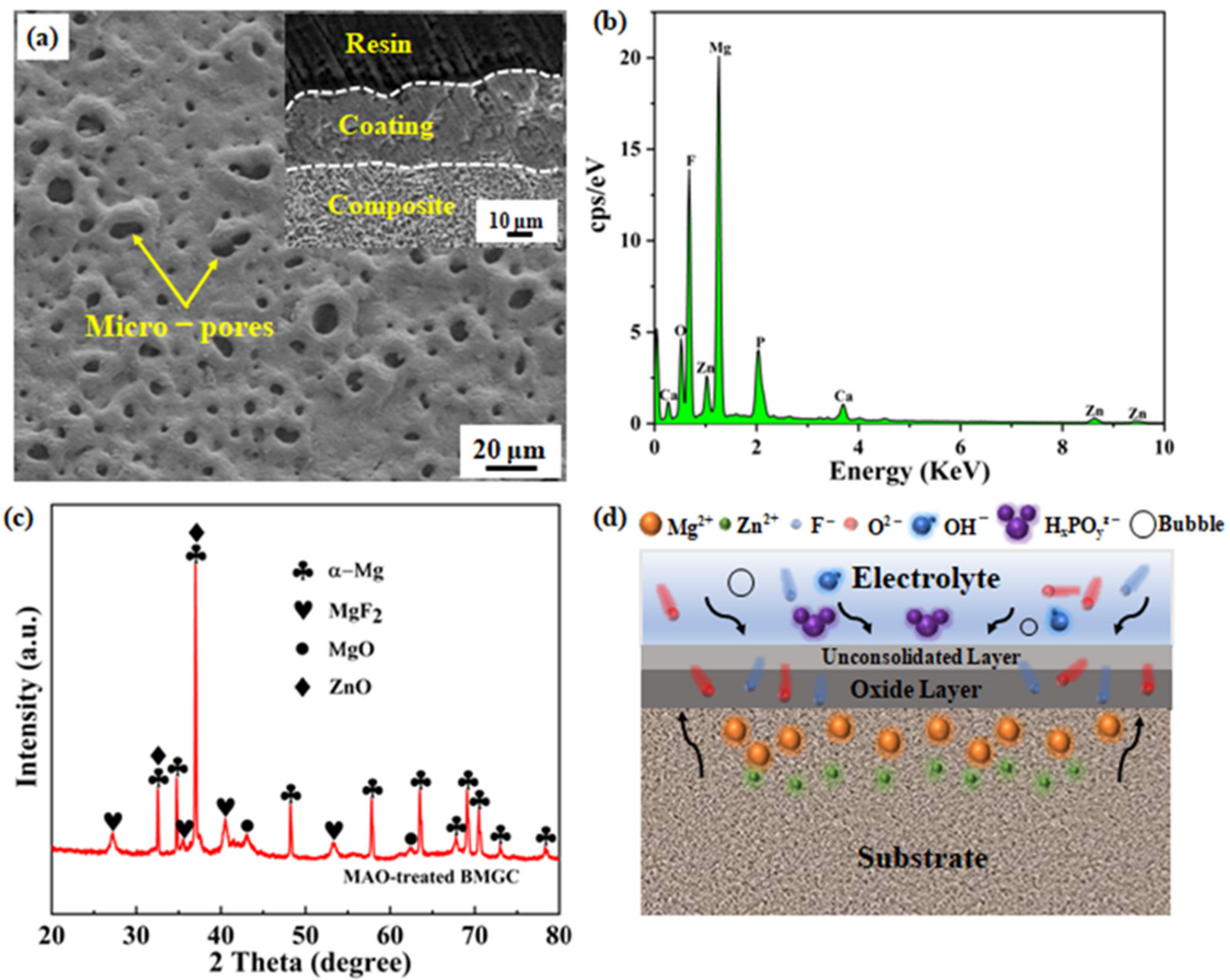
| Element | O | F | Mg | Zn | Ca | P |
|---|---|---|---|---|---|---|
| Wt. % | 11.4 | 34.7 | 33.4 | 12.0 | 2.8 | 5.7 |
| At. % | 16.4 | 42.0 | 31.6 | 4.2 | 1.6 | 4.2 |
| Alloy Specimen | t (μm) | σy (MPa) | σf (MPa) | εp (%) | E (GPa) |
|---|---|---|---|---|---|
| As-cast | 0 | 337 ± 7 | 589 ± 25 | 6.6 ± 0.7 | 54.6 ± 3.3 |
| PEO-treated | 32.4 ±2.0 | 315 ± 11 | 630 ± 9 | 10.5 ± 1.1 | 55.9 ± 2.4 |
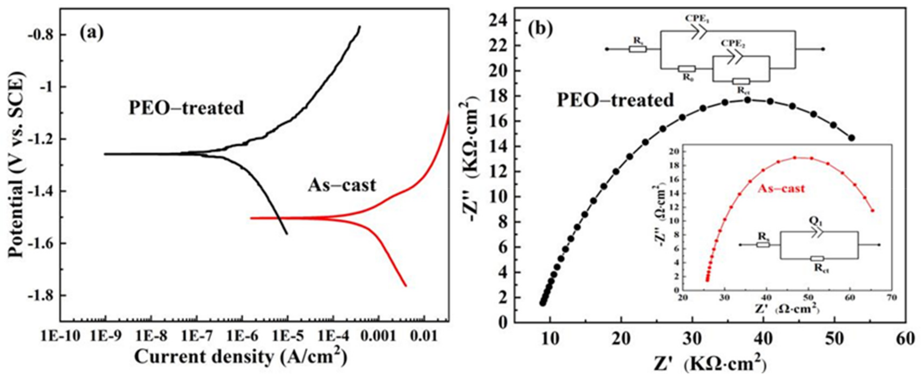
| Alloy Specimen | βa (V·dec−1) | βc (V·dec−1) | Icorr (A·cm−2) | Ecorr (V) | Rp (Ω·cm2) |
|---|---|---|---|---|---|
| As-cast | 0.112 | 0.879 | 3.14 × 10⁻⁴ | −1.483 | 1.38 × 10² |
| PEO-treated | 0.128 | 0.297 | 4.79 × 10⁻⁷ | −1.234 | 8.12 × 10⁴ |
Publisher’s Note: MDPI stays neutral with regard to jurisdictional claims in published maps and institutional affiliations. |
© 2022 by the authors. Licensee MDPI, Basel, Switzerland. This article is an open access article distributed under the terms and conditions of the Creative Commons Attribution (CC BY) license (https://creativecommons.org/licenses/by/4.0/).
Share and Cite
Zeng, Q.; Chen, S.; Song, P.; Li, H.; Zeng, X. Enhanced Plasticity and Corrosion Resistance in Mg-Zn-Ca-Cu Amorphous Alloy Composite via Plasma Electrolytic Oxidation Treatment. Metals 2022, 12, 300. https://doi.org/10.3390/met12020300
Zeng Q, Chen S, Song P, Li H, Zeng X. Enhanced Plasticity and Corrosion Resistance in Mg-Zn-Ca-Cu Amorphous Alloy Composite via Plasma Electrolytic Oxidation Treatment. Metals. 2022; 12(2):300. https://doi.org/10.3390/met12020300
Chicago/Turabian StyleZeng, Qingling, Shuangshuang Chen, Peidi Song, Haodi Li, and Xierong Zeng. 2022. "Enhanced Plasticity and Corrosion Resistance in Mg-Zn-Ca-Cu Amorphous Alloy Composite via Plasma Electrolytic Oxidation Treatment" Metals 12, no. 2: 300. https://doi.org/10.3390/met12020300
APA StyleZeng, Q., Chen, S., Song, P., Li, H., & Zeng, X. (2022). Enhanced Plasticity and Corrosion Resistance in Mg-Zn-Ca-Cu Amorphous Alloy Composite via Plasma Electrolytic Oxidation Treatment. Metals, 12(2), 300. https://doi.org/10.3390/met12020300