Article

A Modelling Study of the Correlation between the Layer Obtained by Selective Transfer and the Dislocations Movement at the Friction Surfaces Limit

1
Department of Machine Elements and Tribology, Polytechnic University of Bucharest, 313 Spl. Independentei, 060042 Bucharest, Romania
2
Department of Biotechnical Systems, Polytechnic University of Bucharest, 313 Spl. Independentei, 060042 Bucharest, Romania
*
Author to whom correspondence should be addressed.
Metals 2022, 12(2), 180; https://doi.org/10.3390/met12020180
Submission received: 20 November 2021 / Revised: 4 January 2022 / Accepted: 14 January 2022 / Published: 19 January 2022

Abstract

:
The selective transfer phenomenon (STP) is based on physico-chemical processes occurring in the contact area of a friction pair, with an element from a copper alloy and allows the metallic transfer of particles of micro/nanometric size, forming a thin superficial tribologically performing layer under energy and relative motion conditions. During the formation of the layer, its crystalline network has an excess of defects and this makes the dislocations to come to the surface. The layer thickness is small, porous, and with comparable dimensions to those of the tensions field of the dislocations. This paper presents a review and analysis of the STP based on dislocations movement to establish and know the tensions field influence, the energy (about 0.25 J/m), and the linear tension of dislocations (~2.42 × 10⁻⁹ N) at the contact surfaces zone of a friction pair, by which we can ensure a low wear state (~4.16 × 10⁻⁵–2.16 × 10⁻⁴ g/min), and a reduced friction coefficient (~0.014–0.034). Therefore, the purpose of the paper is to analyze the STP based on the dislocations movement because is proves the existence (presence), importance, and utility of the dislocations, respectively, the dislocations movements during the conditions’ selective transfer, at the limit of the friction surfaces, under the action of a tensions field, whose components are determined analytically by modelling, together with energy and the linear tension. Also, the layer formed through STP has the property of ensuring during the deformation process an agglomeration of dislocations (structural defects) which protects it from destruction, and therefore, a self-regulation of the equilibrium processes, disturbed during the friction process, to maintain the friction and wear of the friction pairs within reduced limits.

1. Introduction

During the friction process of two materials and in the presence of suitable lubricants, the wear process is manifested as a transfer of material from one element of a friction pair to another (forming a selective layer), a specific process known as the selective transfer phenomenon (STP). This phenomenon lasts until the transferred (tribologically performing) layer reaches an optimal thickness, after which, it may return, totally or partially, to the initial element (repeating alternately). STP will occur in a friction pair if there is one copper-based alloy element in the pair, favorable energy, relative movement, and an adequate lubricant.
The analysis of the STP on the basis of the movement of the dislocations is useful because in the friction process of two elements a tensions and energy field is created around dislocations, which generates forces leading to their detachment, displacement, separation, and anchoring on the contact surfaces. In addition, the layer formed by selective transfer also has the property of ensuring an agglomeration of structural defects (dislocations) which protects it from destruction during the deformation process.
In the process of operation of a friction pair, the friction of adhesion layers and the metal contact interactions depend to a large extent on the state of the friction surfaces [1,2]. During sliding, besides oxidation as a determinant element of the process, there are other processes which favor the dynamics of the phenomenon, namely the formation of a double electric layer on the actual surface; concentration of the superficial dislocations and reduction of the tangential stresses in the surface areas; depolarization and destruction of the oxide layers, having as an effect the acceleration of the corrosion processes; electron emission in the oxide-free areas and once with the variation of the sense of the sliding speed, the formation of metal-organic compounds, of colloids and active substances, which have the effect the transporting metal particles into the contact area.
The parameters with the greatest influence on layer formation with optimal friction and wear properties are the pressure, speed, temperature, and duration of contact [3,4,5].
Phenomenologically, the selective transfer assumes:
  • A reduction in the contact pressure as a result of the increased friction surface;
  • A compensation of tangential tensions by selectively dissolving the thin, superficial layer formed by the two materials in contact;
  • A return of the particles removed by wear into the friction area and formation of a polymerized protective layer.
During the ordinary plastic deformation of a crystalline network, two processes take place: solidification of the crystals and movement (deformation) of the plastic areas, respectively. The solidification is related especially to an interaction of the dislocations, which remain in the crystal lattice and the plastic deformation is related to a modification of the linear defects (dislocations), that come out of the surface through various sliding mechanisms [6,7,8]. The sliding process by which plastic deformation is performed occurs on defined crystallographic planes and in precise directions. The way the sliding process and sliding steps formation take place can be seen in Figure 1a.
In [10,11] it was shown that for metallic monocrystals with known orientation the crystallographic planes on which the slip is produced are usually flat, with a maximum atomic density and a maximum interplanes distance, and in the sliding plane, the sliding always occurs in a direction of maximum packing; the combination between a sliding plane and a sliding direction, from that plane, forms a sliding system; in a certain crystalline grain, this first occurs on that sliding system in which the tangential component of the tension (TCT) in the sliding direction has a maximum value [10,11]. Therefore, slipping into a crystalline grain or a mono-crystal is provoked not by all the applied tension, but only by the TCT in the direction of slipping (Figure 1b).
This paper analyzes the structure of the superficial selective protective layer (which behaves very well during rubbing and wear) formed during the friction process, by material transfer, specific to the STP. Due to the movement of dislocations in this thin, tribologically performing layer, obtained under special conditions, it turns out that, the deformation processes ensure an agglomeration of dislocations (structural defects) which protects it from destruction.
Hence, the aim of this paper is the analysis of the STP in correlation with dislocations theory, based on the movement of the dislocations that is useful and has importance, because in the friction process and under selective transfer conditions, a tensions, energy and linear tension field is created around dislocations, which generates the forces necessary for their detachment, displacement, and anchoring, on contact surfaces, where the selective layer (already formed) is present, protecting it against destruction. Determination by modeling and knowledge of the tensions field, energy, and linear tension of the dislocations, are necessary, because the tensions field components’ size depends on the movement of the dislocations, having as an effect the maintenance of friction and wear of the friction pairs within reduced limits, by self-regulation of the phenomena and the equilibrium processes, disturbed during the friction process.

2. Establishing the Tangential Component of the Sliding Stress/Tension (TCT) and of Methodology

The TCT can be determined mathematically, if a monocrystal of cylindrical form (Figure 1b), with base S, subjected to the traction of an axial force F, is considered, namely:
TCT = (F·cosλ)/(S/cosα) = (F/S)·cosα·cosλ
The value of the trigonometric factor, cosα∙cosλ in relation (1) depends on the orientation of the force in relation to the plane and the direction of the crystal sliding. This trigonometric factor may have a maximum value, which is 1/2 for α = λ = π/4, and a minimum value, which is zero if the angle α is known (from Figure 1b) and λ = π/2, respectively.
In accordance with [10], experimentally it was found that sliding in a crystal occurs on a sliding system when the TCT reaches a critical value in that system, called the critical sliding component or shear stress, τ. The presence of a softer protection layer on the friction surface, relative to the base material, is a necessary condition for conducting a selective transfer by friction. In this way, it intervenes to create a positive gradient of the shear stress in the friction surface area of the two metallic materials (here bronze/steel or brass/steel, etc.) [12]. During the friction process of the copper alloys what takes place, primarily, is a redistribution of the alloying elements that determines the behavior of the metal in the contact area. The results of the analysis of structural changes in the thin superficial layers prove that a selective transfer is characterized by certain structural changes. These structural changes represent a necessary condition, for the friction process, almost without wear. This condition supposes the formation on the friction surface of a layer of pure copper with special properties, such as a high density of dislocations and a high degree of saturation of point defects. For this reason, it was considered useful to study the selective transfer through dislocations movement.
As shown in [9], at the beginning of the friction tests, dislocations slip in a relatively disordered way on those planes where the smallest shear stress appears. Such sliding is related to the absence of obstacles for the movement of the dislocations, which are, in fact, agglomerations of dislocations. In addition, as the trial duration and external load increase, dislocations slippage takes place in the network, whereby a state of tension is created. As the frictional stress continues, the stage of so-called dynamic restoration [13] in other slipping planes, followed by the removal of defects with signs to the contrary occurs [14].
As a consequence of the agglomeration of dislocation actions, a stress that exceeds the theoretical shear resistance can appear in their upper part, which is precisely τ [15].
During the selective transfer process in the areas of the friction surfaces, the formation of a superficial layer based on copper can lead to a decrease in the effective shear tension in the base material, and thereby, the agglomeration processes are reduced. A reduction in tangential stress can then prove insufficient to overcome the interaction forces.
As a result, there is the possibility of the formation of branched dislocations, both at the layer surface and between the layer and the base material, which make it difficult for the output of the dislocations, directly to the surface and lead to an increase in the stresses, in the material below this layer [3,16,17].
Therefore, as a result an energy accumulation occurs to a significant extent in the areas close to the surface. This ensures a state, which lasts relatively long, with particularly low wear of a bronze/steel friction pair [18,19].
In other words, it is to be expected that the selective layer that has been transferred between the two friction surfaces will reduce the wear because the dislocations in this layer are rejected by the limit surface of the phases [9,20,21,22,23].
From experimental research [2,3,24,25,26] it was found that this phenomenon does not appear, for situations where the thickness of the layer can be compared to the tension field radius of action. For this reason, defects cannot be blocked because they are favored by the thermal energy generated during friction, an energy that is comparable to the energy of activation of the movement of the dislocations.

3. Theoretical Tension at the Plastic Deformation in the Conditions of Selective-Transfer

The defects from crystal structure play an important role in determining many properties of solid bodies, strongly influencing the physicochemical properties of these and underpinning some phenomena like diffusion in solids, semi-conductivity [10,27], etc. which are specific to the STP. The typical representatives of defects are dislocations, which can be linear (marginal) or helical.
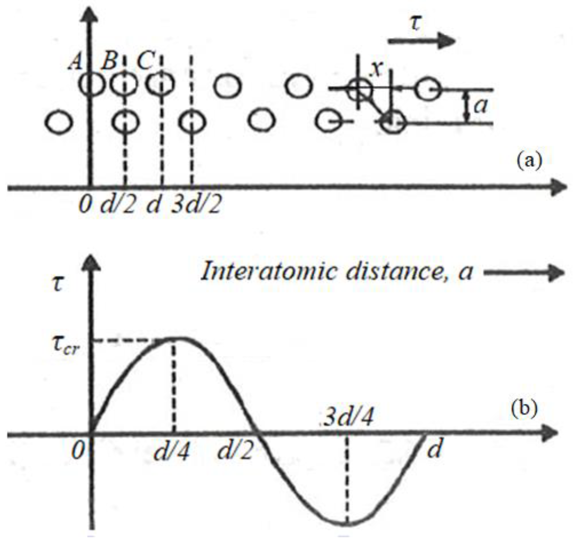
It is known from [8,27,28,29] that, the irreversible displacement of atoms in metallic crystals during plastic deformation also occurs by sliding inside the grains and this starts to occur only at low temperatures. Slipping in a perfect crystal is synchronous, which implies the simultaneous displacement of all atoms in the upper plane in ratio with the lower one (Figure 2a). The slip occurs along those planes and in the directions with maximum atomic density (maximum packaging direction).
The shear tension, τ, required to produce sliding, to bring the atoms to positions A, B, C (Figure 2a) corresponding to the travel distance x, respectively, will be maximum and equal to τcr (Figure 2b) and given by the following relationship [9,12,27]:
τcr = G/2π.
More precise calculations indicate for the theoretical deformation tension [9,12,27], the value:
τcr = G/30
where G is the transverse resistance modulus (the shear modulus).
In [10], it has been shown that the theoretical resistance to deformation by shear is much higher than that obtained experimentally. This difference is due to the imperfections of the crystal lattice of the actual crystals and, in particular, to the presence of network defects (dislocations). This is explained by the fact that in imperfect crystals the slip does not occur simultaneously on the entire surface of the sliding plane, but gradually, by migrating the dislocations into the sliding plane under the action of the tangential forces [2,3].
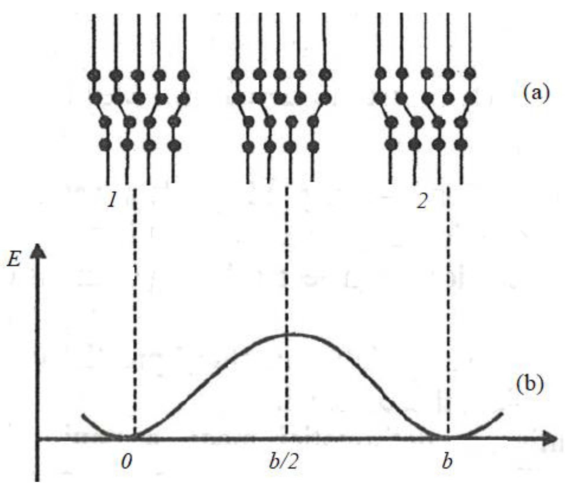
Tension is required for the movement of a mobile dislocation on a slipping plane, which can be understood from Figure 3 [9,12]. Figure 3a shows how a dislocation moves to the right from position 1 in position 2 of a crystalline network with an interatomic distance equal to b (b being the size of the Burgers vector). Figure 3b shows the variation of the dislocation energy for its various locations, with minima in symmetric positions 1 and 2 and with the maxima at the half-distance between these positions. The passing of dislocation from one position to another through intermediate configurations with increased energy requires the application of a tangential tension/stress τ, which is calculated with the following relation [3,10]:
τ = [2G/(1 − νp)]·1/el/b,
where: b is the interatomic distance on the slip direction (b is the magnitude of the Burgers vector of the dislocation); l is the width of the dislocation, equal to several interatomic distances in the metallic crystals and νp is Poisson’s coefficient.
By comparing the relationship (4) with (2) and (3), it is found that the tension is less than the slip theoretical resistance with a few orders of magnitude because of the exponent 1/b. The width of dislocations l is higher in metallic crystals (i.e., the tangential tension is lower) due to the non-directed metallic connections; this allows network disturbances from the dislocation area to extend over many interatomic distances.

4. The Forces That Cause Movement of Dislocations

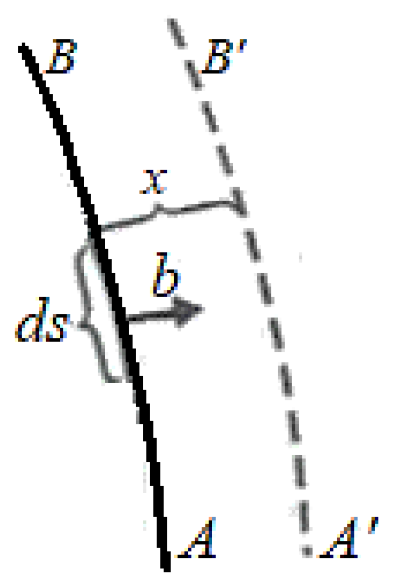
The deformation resistance is dependent on the movement of the dislocations, the movement being controlled by the forces acting on the dislocations. The movement of dislocations is of practical importance because it is accompanied by plastic deformation of the body [30]. The force that causes dislocations displacement is proportional to the Burgers vector of the dislocation and the applied tension [10,22,31]. To determine the mean deformation of a crystal, at any displacement x of the dislocations contained therein, consideration is taken, in the sliding plane represented in Figure 4, of the dislocation AB with the Burgers vector, b; this dislocation moves to the dotted position AB’ under the force action which causes the displacement.
If an external force, F, determines the plane of sliding the tangential component of tension (the shear tension) [27,32], τ, then the tangential force acting on the unit of dislocation length is Fd and:
Fd = τ·b
The relationship (5) is valid for the displacement of the dislocations under the action of tangential tensions (displacement by slip), and when the displacement of the dislocations happens under the action of the normal stretching or compression stresses (displacement by climb) [27,32], and Fd, becomes:
Fd = σ·b
Thus, on a dislocation that is in a tensions field, forces act that causes its movement. The stresses/tensions field can be external or combined, having the same effect on dislocation. The relations (5) and (6) that define the size of the force acting on a dislocation are established for external tension fields. It follows that these forces are also applicable to internal or combined tension fields. Therefore, it can be said that the dislocations in the crystals interact with each other, and the force of interaction can be one of attraction or repulsion, depending on the sign of the dislocations (positive or negative). Thus, under selective transfer conditions, the interaction between dislocations and the free surface of the superficial selective layer must be taken into account. In this case, the unitary interaction force tends to move the dislocations to the surface under the action of tangential tensions (displacement by slipping), and described by the following relation [9]:
Fd =Gb2/2πs,
where s represents the distance between the dislocation and the free surface. This is why it is necessary to know the tensions field, energy, and linear tension of dislocations, which will be established and determined further.
On the other hand, the components of the tension that generate a force on the helical dislocation which can move only by sliding are both τθz and τrz, respectively, and the components of the tensions that generate a force on the linear dislocation and can be moved both by sliding and by climbing are τθr and σrr (see Figure 5).
The sliding motion of a linear dislocation is limited to its sliding plane, defined by the dislocation line and the Burgers vector (the vector perpendicular to the dislocation line) and moves through climbing or diffusion (Figure 6).
However, in the case of helical dislocation the Burgers vector is parallel to the dislocation line, so it does not define a unique sliding plane and this enables helical dislocations to execute a special type of displacement by sliding, called deviated sliding (“cross-slip”). The activation energy required for the deviated slip movement of the helical dislocations is very low (<1 eV), considerably lower than the activation energy for the displacement by diffusion of the linear dislocations; this explains the greater mobility of helical dislocations as the temperature rises.

5. The Stresses/Tensions Field of a Dislocation

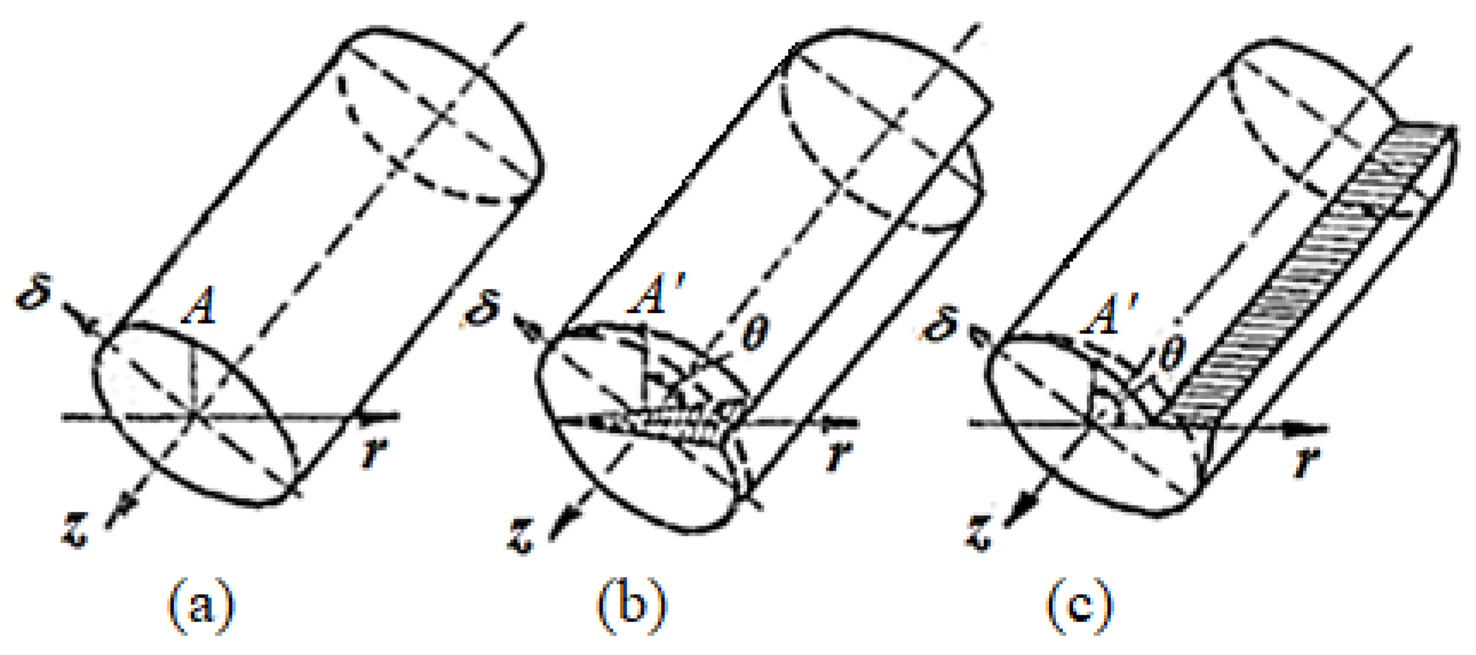
Any dislocation is surrounded by a tensions field that generates forces that produce the displacement of the dislocations. This field can be produced by the application of some external tensions or the existence of defects of the crystal lattice, such as dissolved foreign atoms, precipitated secondary phase particles, and other dislocations [24,26,32]. The components of this field can be determined with help by the elasticity theory, but only from a distance ρ0 from the core of the dislocation because, in the immediate vicinity of the core of dislocation, deformation is too large to be treated with the elasticity theory (ρ0 is the dislocation core radius). The way how to form a dislocation is shown in Figure 7. To establish the components of the tension caused by a dislocation a cylindrical body is considered, which has an axis parallel to the z-axis (Figure 7a).
In this body we introduce a dislocation and proceed according to the following imaginary mechanism:
  • the body is radially cut down the plane δ = 0 to the point where the dislocation will be located (possibly up to the point r = 0, δ = 0);
  • a force moving the surfaces obtained by cutting one above the other with the distance b/2 (b being the size of the Burgers vector) is applied so that the total displacement is b;
  • the two surfaces are brought together, by cutting.
If the driving force produced a displacement b parallel to the z-axis, the dislocation obtained is a helical one (Figure 7b), and if the displacement b is perpendicular to the z-axis, the dislocation is linear (Figure 7c). The components of the tensions field produced by a helical dislocation can be determined with the notations in Figure 7b. If prior to displacement, the point A (see Figure 7a) has the coordinates x, y, z, these deformations become r + u, δ + v, and z + w (see Figure 7b), where u, v, and w are the displacements of the point A along with the r, δ, z-axes.
It is noted that:
{ u = v = 0 ; w = b 2 π θ ,
where θ the angle formed by the r-axis with the right that joins point A with the origin of the coordinate system, u represents the displacement along the r-axis; v is the displacement along the δ-axis; w is the displacement along the z-axis. Hence, the deformation specific components, after the r, δ, z directions, can be written as [28,29,30]:
ε r = u r ; ε δ = 1 ρ · v δ ; ε z = w z ,
where ρ is the radius of the cylindrical area centered on the dislocation line, to the point where the tension is calculated, and the angular deformations are [29,31]:
{ γ δ z = 1 ρ · w δ + v z ; γ z r = u z + w r ; γ r δ = v r v ρ + 1 ρ · u δ .
Based on the relations (8) and (9), since u = v = 0, for a helical dislocation oriented in the z-direction (see Figure 7b), the tensions field has a component single and can be expressed in cylindrical coordinates, according to the notations from Figure 5, in the form:
τ δ z = G ρ · w δ = G b 2 π ρ .
The tensions field according to (9) and (10) has only one component of tension, non-zero, τδz from the relation (11). Therefore, in the case of helical dislocations, there are no normal tensions but only tangential tensions, the tensions field being symmetrical.
When the tensions field around linear dislocations is asymmetrical in the sense that the plane of sliding divides the crystal into two halves; in the half containing the additional half-plane (see Figure 3a) the tensions are of compression, in the other half the tensions are of tensile (stretching).
For the determination of the tensions field of a linear displacement, is consider Figure 7c, from which results in the linear displacement components in the system of cylindrical coordinates:
{ u = b 2 π [ θ + sin 2 θ 4 ( 1 v p ) ] ; v = b 2 π [ ( 1 2 v p ) ln ρ 2 ( 1 v p ) + cos 2 θ 4 ( 1 v p ) ] ; w = 0 .
Considering the relations (10), the following expressions are obtained for the components of the tension in cylindrical coordinates:
{ σ r r = σ δ δ = G b 2 π ( 1 v p ) · sin θ ρ ; σ z z = G · b · v p 2 π ( 1 v p ) · sin θ ρ ; τ r δ = τ δ r = G b 2 π ( 1 v p ) · cos θ ρ ,
where G represents the transverse elastic modulus; vp is the Poisson coefficient; b is the size of Burgers dislocation vector and ρ is the radius of the cylindrical area centered on the dislocation line, to the point where the tension is calculated.

6. Energy and Linear Tension of Dislocations

6.1. Dislocations Energy under Selective Transfer Conditions

The presence of dislocations in a crystal leads to displacement of atoms in the dislocations area, outside their equilibrium positions, from the crystalline network, having as an effect the elastic deformation of the network and the creation of a tensions field around the dislocations.
To introduce a dislocation into a crystal mechanical work is consumed, which is conserved under the form of the energy of elastic deformation of the crystalline lattice. The difference between the crystalline network energy with dislocation and the one without dislocation is equal to the consumed energy for the introduction of the dislocation, called the dislocation energy.
The energy of a dislocation depends on its length L, and for dislocations of the same length, the energy is determined by the type of the dislocation (linear or helical). The energy of dislocation can be determined either by calculating the deformation energy or by calculating the mechanical work required to introduce the dislocation into the crystal. Thus, to determine the energy of dislocation, we will follow the second path.
For this, the cylindrical body in Figure 7a is considered, with the outer radius ρ and the inner radius ρ0, surrounding it, is located along the axis of the cylinder reported to the system of the cylindrical axes (r, δ, z), having the sense given by the positive direction of the z-axis; then the mechanical work required to the dislocation formation is equal to the energy required the displacement of the surfaces obtained by cutting with the δ = 0 plane (see Figure 7c).
This energy is equal to the product between the relative displacement b/2 and the force F, which produced this displacement. Noting the surface element on which the displacement took place with dS and because dS = L·dr, the elemental force, dF will be:
d F = τ δ r d S = τ δ r · L · d r ;
whence the force results, F, is:
F = R 0 R d F = R 0 R τ δ r · L · d r .
If for a linear dislocation, τδr is given by the relation (13), then the energy of the linear dislocation is:
E l = b l 2 ρ 0 ρ τ δ r d r = G b 2 L 4 π ( 1 v p ) ρ 0 ρ cos θ ρ d r .
For plane δ = 0, cosθ = 1, so:
E l = G b 2 L 4 π ( 1 v p ) ln ρ ρ 0 .
If the same thing is done for a helical dislocation, it is found that its energy will be:
E e = b L 2 ρ 0 ρ τ δ z d r = G b 2 L 4 π ρ 0 ρ d r R = G b 2 L 4 π ln ρ ρ 0 ,
where τδr is given by the relationship (13).
From relations (17) and (18) it follows that the energy that comes back on the dislocation length unit will be:
  • for linear dislocation:
    E l = G b 2 4 π ( 1 v p ) ln ρ ρ 0 ;
  • for helical dislocation:
    E e = G b 2 4 π ln ρ ρ 0 .
Since, ρ0 = 3 × 10⁻¹⁰ m and ρ = 10−6 m [29], it results that along the length unit of the linear dislocation an energy approximately equal to Gb2, that is Gb3, respectively, comes back on a dislocation length equal with an interatomic distance, [27,28,29]. For copper, since G = 4 × 10¹⁰ N/m2 and b = 2.5 × 10⁻¹⁰ m, the energy on the dislocation length is approximately 0.25 J/m or about 6.25 × 10⁻¹⁹ J on an interatomic distance of the dislocation length (1 eV on an interatomic distance).
A mixed dislocation has energy equal to the sum of the contributions of the linear and helical dislocations components, namely:
E m i x t = G b 2 L 4 π ( 1 v p ) · ln ρ ρ 0 ( 1 v P cos 2 α ) ,
where: α is the angle between the Burgers vector and the dislocation axis, and the other dimensions have the significances above:
E = G b 2 L 4 π ( 1 v p ) · ( 1 v P cos 2 α ) · ln 1 b d ,
where: d is the dislocations density.
The energy of the dislocation heart contributes approximately 10% to the total energy of dislocation [27]. Analyzing the dislocations energy expressions, the following findings result:
  • because the elastic energy of dislocation is proportional to lnρ, it grows slowly with the radius; as a result, dislocations possess a long distance tensions field, which explains the interactions between dislocations and, between dislocations and other network defects. Hence, due to the same mode of energy distribution at the distance long, the energy stored in the core of the dislocation is small and can be neglected (being less than one-fifth of the total energy for ρ > 10−6 m);
  • since the elastic energy of dislocation is proportional to the square of the Burgers vector, stable dislocations in metallic crystals will be those with the smallest Burgers vector, as they possesses the lowest elastic energy;
  • the elastic energy of a linear dislocation is greater that than of a helical dislocation with a factor 1/(1 − νp); for Poisson’s coefficient νp = 0.33, this factor is 3/2;
  • the elastic energy of a dislocation is proportional to its length, then, dislocations tend to-and reduce their length; as a result, dislocations in the form of some straight segments are more stable than the curved mixed dislocations.

6.2. Linear Tension of the Dislocations in the Selective-Transfer Conditions

The linear tension of dislocation represents a property derived from the last finding in Section 6.1. By analogy with the superficial tension of the liquids, which tends to shrink their surface, the linear tension of the dislocation is defined as a force T guided on the direction of the dislocation, which tends to reduce its length. Based on relationships (16) and (18) it results that dislocation will tend to have a length, as small as possible, attained by shrinking its associated energy, to get in this way a configuration as close as possible to the equilibrium configuration. Under these conditions, the linear tension, T is obtained by deriving the dislocation energy in relation to the length L; preceding in this way, from the relation (16) it results that the linear tension of a linear dislocation becomes:
T = d E l d L = G b 2 π ( 1 v p ) · ln ρ ρ 0 .
For a helical dislocation, the same expression applies, but omitting the factor (1 − νp). Due to the action of the linear tension, a dislocation cannot be maintained under the curved form unless an external tension is exerted on it which balances the linear tension. Therefore, to increase the length of a dislocation, on the sliding plane, it must apply a tangential tension, τ large enough to overcome the linear tension T.
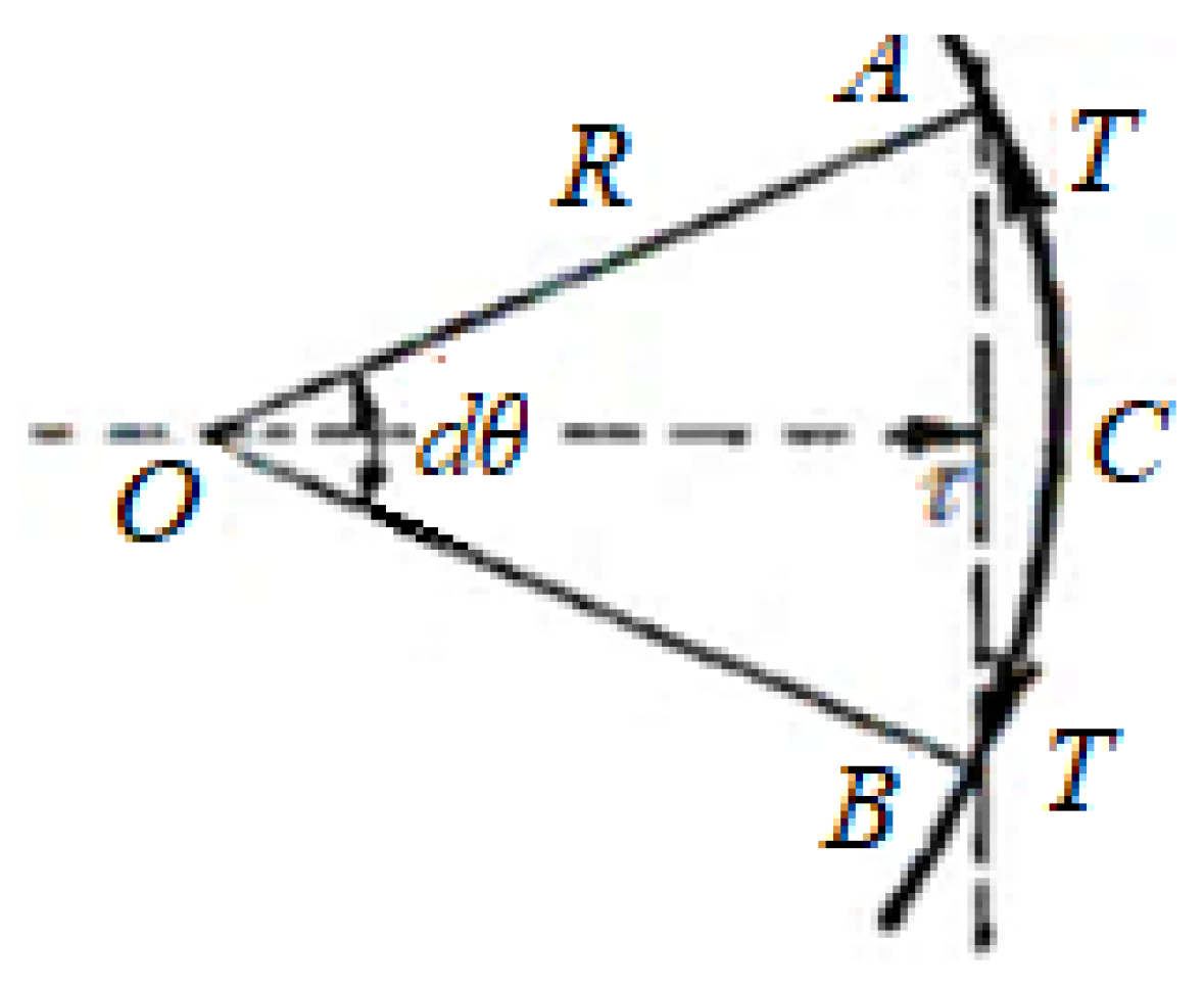
The tangential tension, τ, necessary can be determined by considering an AB dislocation that increases its length by bending; the ends A and B remaining fixed (Figure 8).
In order to curve the AB dislocation, the tension from O to C must be applied, the length of the arc obtained being dl. So, the bending action exercised by the tension τ, which generates the force, τ·b·dl, and it opposes the linear tension T, it tends to keep it straight.
The equilibrium condition is:
τ · b · d l = 2 T sin d θ 2 .
For small angles, sin d θ 2 d θ 2 and, taking into account that d l = R d θ , where R is the radius, it results:
τ · b · d l = T · d θ = T · d l R   or   τ = T b

7. Results and Discussion

It was seen that, on a dislocation that is in a tensions field, forces act that cause its movement. The tensions field can be external, internal, or combined, having the same effect on dislocation.
It is understandable based on the above (Section 4) that in the case of the internal tensions field the dislocations displacement occurs on account of the reduction of the elastic energy of the field, and a modify of these tensions takes place.
The parameters of the crystalline structure of the analyzed and researched bronzes are confused with those of copper, because it is the dominant chemical element (>85%), and are: ρ0 = 3 × 10⁻¹⁰ m, ρ = 10−6 m, b = 2.5 × 10⁻¹⁰ m, G2 = 4 × 10¹⁰ N/m2, νp = 0.33, s = 2.526 × 10⁻¹⁰ m, L = 2.5 × 10⁻¹⁰ m, α = 70°32′, the energy on the dislocation length is approximately 0.25 J/m, and for comparison will be presented G1 = 8 × 10¹⁰ N/m2, for steel.
Thus, for a steel/bronze pair lubricated with glycerin, the dislocations formed in the steel and during start-up will always be attracted by the phase boundary surface, as G1 is considerably larger than G2 (G1 >>> G2, see the values above), for which the surface layer will solidify on the steel element. At the same time, more surface layers will solidify on the bronze element than on the steel element, because the dislocations formed in the layer near the surface are rejected from the separation surface.
The copper layer formed under the selective-transfer conditions alters the conditions for the interaction of the surface areas as well as of dislocations, in the separation layer of the surfaces. Under these conditions, the dislocations produced in the steel are attracted by the separation surface, because G1 > G2. For bronze, the condition G1 < G2 is valid if it can be assumed that the copper layer possess a solid crystal lattice. In this case, the areas near the friction surface of the bronze element will be modified, as the dislocations are rejected from the surface.
Taking into account the results of the research on the structure of the copper layer under selective-transfer conditions [3,33,34], where a layer softening is found during the friction process, then the adhesion at the areas of surface must be weaker. As a result, there is an accumulation of elastic energy in areas close to the surface. This ensures a condition, that lasts relatively long, leading to a particularly low wear of the friction pair.
Therefore, at the contact the two materials (bronze/steel) with the shear modules (transverse resistance modules) G1 (for base material, steel) and G2 (for the selective layer, bronze), the dislocations in steel with module G1 are displaced at the boundary of the two surfaces in contact, then condition G1 > G2 is met; and are rejected when condition G1 < G2 is valid. These conditions are also valid for the description of the interaction energy of dislocations with a surface covered with a homogeneous layer of thickness h.
Thus, if G1 > G2, the dislocation is drawn all the time to the surface, and if G1 < G2, the dislocation is drawn to the surface for, s >> h (s—distance from the surface at which the dislocation is located) and, s << h, the dislocation is rejected from the surface [9]. From this statement we can formulate the equilibrium condition, namely: if G2 > G1, then the dislocation is in equilibrium with the surface and sh.
Now, replacing them in relation (21) one can determine the density of dislocations, d for the bronze/steel pair, which works in the conditions of selective transfer and is obtained: d = 2.483 × 10¹⁴ dislocations/m2, T = 2.42 × 10⁻⁹ N, Fd = 1.56 N/m, and τ = 6.24 × 10³ MPa. By comparing the value of the calculated mixed dislocation density (2.483 × 10¹⁴ dislocations/m2) with the value obtained experimentally by ferromagnetic resonance which is 2.55 × 10¹⁴ dislocations/m2 we can confirm the correlation between the results obtained analytically and the experimental ones. Thus, it was proved that there is a correlation between theory and experiment; the results from experiments are validated by modeling, based on elasticity theory, but only from a distance very small from the core of the dislocation, using the model of a cylindrical body having an axis parallel with a direction of the tension field. At the same time, it is demonstrated that for the friction pairs that operate in the conditions of selective transfer, the specific dislocations are the mixed ones.

8. Conclusions

At the contact of two materials with the shear modules different (here bronze/steel) G1 (for steel—the base material) and G2 (for bronze—the selective layer), the dislocations can be found in the following situations:
  • the dislocations in the material with the G1 module are drawn to the limit of the two surfaces in contact when the condition G1 > G2 is satisfied;
  • the dislocations in the material with the G1 module are rejected when the condition G1 < G2 is valid.
These conditions are valid to the description of the energy of interaction of the dislocations with a covered surface with a homogeneous layer of thickness h. Hence, when the condition G1 < G2 is satisfied, the dislocation is drawn to the surface for, s >> h, and this is rejected from the surface for, s << h, and if G2 > G1, then the dislocation is in equilibrium with the surface and sh.
Because G1 >>> G2, at the contact of bronze/steel pair lubricated with glycerin, the dislocations formed in the steel, even at the startup will always be attracted to the limit surface of the phases, i.e., a superficial layer will adhere on the steel element. At the same time on the bronze element a superficial selective layer will adhere more than on the steel element, because the dislocations formed in the layer near the surface are rejected from separation surface.
In the selective-transfer conditions a copper layer formed, which alters the conditions for the interaction of superficial areas of the surfaces, as well as of dislocations, in the separation layer of the surfaces.
Based on the results of the research on the structure of the copper layer under the selective-transfer conditions, a soaking of the layer during the friction process is found, hence, the adhesion at the areas of surface must be more reduced. As a result, an accumulation of elastic energy takes place in the areas close to the surface, which assures a state which lasts relatively long and leads to particularly low wear of the friction pair.
To prove these affirmations, it was necessary to determine the density of dislocations in the superficial areas, which is very difficult but by using ferromagnetic resonance, this is possible. This assumes the determination of ferromagnetic resonance lines at a certain frequency. Through measuring the width of the ferromagnetic lines, the dislocations density can be estimated, because ferromagnetic line widening contributes to both the dislocations and the asperities of the surface.
During a selective-transfer, use of a tension-active lubricant (glycerin) results in a dislocation density of 2.55 × 10¹⁰ dislocations/cm2, which is very close to the one determined through the analytical calculations (2.483 × 10¹⁰ dislocations/cm2), and under the usual friction conditions, the density of the dislocations is of 7.7 × 10¹⁰ dislocations/cm2. The result proves that the structure of the dislocations changes very little during a selective transfer, which ensures a very small wear condition, as well as a reduced friction coefficient in the contact surfaces area.
The analysis of the STP in correlation with dislocations theory is useful and has importance, because in the friction process and under selective transfer conditions a tensions field is created, around dislocations, the energy and the linear tension, which generates forces necessary for their detachment, displacement and anchoring, on the contact surfaces, where the selective layer (already formed) is present, protecting it from destruction.
The analysis of the STP based on dislocations movement allowed us to establish and know the tensions field influence, the energy (about 0.25 J/m), and the linear tension of dislocations (~2.42 × 10⁻⁹ N) in the contact surfaces zone of a friction pair, which ensures a low wear state (~4.16 × 10⁻⁵–2.16 × 10⁻⁴ g/min) and a reduced friction coefficient (~0.014–0.034), respectively. Hence, it was proved that there is a correlation between theory and experiment and the results from experiments are validated by modeling.
The existence, importance, and utility of the dislocations and their movement in the conditions selective transfer, respectively, at the limit of the friction surfaces under the action of a tensions field was proved.
The layer formed through STP has the property of ensuring in the deformation process an agglomeration of structural defects which protects it against destruction, thus is assuring the self-regulation of the equilibrium processes, disturbed in the friction process, with the aim to maintain the friction and wear of the friction pairs within reduced limits.
Therefore, knowing the tensions field, energy, and linear tension of the dislocations, in the conditions of selective transfer is important and useful for complexity analysis of the STP and the practical results for the operation of friction pairs with low wear, respectively, and reduced friction coefficients.

Author Contributions

Conceptualization, F.I. and G.I.; methodology, F.I. and G.I.; validation, F.I. and G.I.; formal analysis, G.I.; investigation, F.I.; resources, F.I.; data curation, F.I.; writing—original draft preparation, F.I.; writing—review and editing, F.I.; visualization, F.I.; supervision, F.I.; project administration, F.I.; funding acquisition, G.I. All authors have read and agreed to the published version of the manuscript.

Funding

This research received no external funding.

Institutional Review Board Statement

Not applicable.

Informed Consent Statement

Informed consent was obtained from all subjects involved in the study.

Data Availability Statement

Not applicable.

Acknowledgments

We thank the technicians who provided us with the equipment and materials needed for the experiments.

Conflicts of Interest

The authors declare no conflict of interest.

References

  1. Sangid, M.D. The physics of fatigue crack initiation. Int. J. Fatigue 2013, 57, 58–72. [Google Scholar] [CrossRef]
  2. Bjerkén, C.; Melin, S. A tool to model short crack fatigue growth using a discrete dislocation formulation. Int. J. Fatigue 2003, 25, 559–566. [Google Scholar] [CrossRef]
  3. Anderson, P.M.; Hirth, J.P.; Lothe, J. Theory of Dislocations, 3rd ed.; Cambridge University Press: Cambridge, UK, 2018; p. 718. [Google Scholar]
  4. Szekely, J.; Themelis, J.N. Rate Phenomena in Process Metallurgy; John Wiley & Sons, Inc.: Hoboken, NJ, USA, 1991. [Google Scholar]
  5. Ilie, F. Tribological behaviour of the steel/bronze friction pair (journal bearing type) functioning with selective mass transfer. Int. J. Heat Mass Transf. 2018, 124, 655–662. [Google Scholar] [CrossRef]
  6. Cai, W.; Nix, W.D. MRS-Cambridge Materials Fundamentals: Imperfections in Crystalline Solids; Cambridge University Press: Cambridge, UK, 2016; p. 532. [Google Scholar]
  7. Kuksenova, L.I.; Polyakov, S.A.; Lapteva, V.G.; Alekseeva, M.S. Mechanical Properties of Surface Layers of Structural Steels after Nitriding and Possibilities of Adaptation of Their Nanostructure to Contact Deformation. Met. Sci. Heat Treat. 2015, 57, 436–442. [Google Scholar] [CrossRef]
  8. Zhai, W.; Bai, L.; Zhou, R.; Fan, X.; Kang, G.; Liu, Y.; Zhou, K. Recent Progress on Wear-Resistant Materials: Designs, Properties, and Applications. Adv. Sci. 2021, 8, 2003739. [Google Scholar] [CrossRef]
  9. Ilie, F. Study Tribological of Thin Superficial Layers Formed in the Friction Couples through Selective Transfer; Technical Publishing House: Bucharest, Romania, 2002. [Google Scholar]
  10. Laughlin, D.E.; Hono, K. Physical Metallurgy, 5th ed.; Laughlin, D.E., Hono, K., Eds.; Elsevier: Amsterdam, The Netherlands, 2015; p. 1. [Google Scholar]
  11. Field, D.P.; Merriman, C.C.; Allain-Bonasso, N.; Wagner, F. Quantification of dislocation structure heterogeneity in deformed polycrystals by EBSD. Model. Simul. Mater. Sci. Eng. 2012, 20, 024007. [Google Scholar] [CrossRef]
  12. Ilie, F. Diffusion and mass transfer mechanisms during frictional selective transfer. Int. J. Heat Mass Transf. 2018, 116, 1260–1265. [Google Scholar] [CrossRef]
  13. Kaufman, M. Order and Disorder, Science Essetials for the Non-Scientist; Imperial College Press: London, UK; Emory University: Atlanta, GA, USA, 2011. [Google Scholar] [CrossRef]
  14. Havner, K.S. Finite Plastic Deformation of Crystalline Solids; Cambridge University Press: Cambridge, UK, 2009. [Google Scholar]
  15. Arnaudov, N.; Kolyshkin, A.; Weihe, S. Micromechanical modeling of fatigue crack initiation in hydrogen atmosphere. Mech. Mater. 2020, 19, 103557. [Google Scholar] [CrossRef]
  16. Safonov, V.; Shishurin, S.; Gorbushin, P.; Chumakova, S.; Kolomeichenko, A.; Kuznetsov, Y.; Kalashnikova, L. Investigation of Structure and Wear Resistance of Nanocomposite Coating of Chemical Nickel. Tribol. Ind. 2018, 40, 529–537. [Google Scholar] [CrossRef]
  17. Ilie, F. Study of Superficial Layers Obtained by Selective Transfer in the Friction Couples. Eur. J. Eng. Res. Sci. 2017, 2, 54–58. [Google Scholar] [CrossRef] [Green Version]
  18. Marshakov, I.K. Anodic Dissolution and Selective Corrosion of Alloys. Prot. Met. 2002, 38, 118–123. [Google Scholar] [CrossRef]
  19. Bowden, F.P.; Tabor, D. The Friction and Lubrication of Solids; Oxford Classic Texts in the Physical Sciences; Clarendon Press: Oxford, UK; Oxford University Press: New York, NY, USA, 2001; p. 374. [Google Scholar]
  20. Garkunov, D.N.; Polzer, G. Analysis of wear and selective transfer by friction. Saf. Eff. Tribotechnol. 1992, 1, 9–11. [Google Scholar]
  21. Garkunov, D.N.; Polzer, G. International conference, selective transfer and friction coverage. Saf. Eff. Tribotechnol. 1992, 1, 7–8. [Google Scholar]
  22. Calcagnotto, M.; Ponge, D.; Demir, E.; Raabe, D. Orientation gradients and geometrically necessary dislocations in ultrafine grained dual-phase steels studied by 2D and 3D EBSD. Mater. Sci. Eng. A 2010, 527, 2738–2746. [Google Scholar] [CrossRef]
  23. Wilkinson, A.J.; Randman, D. Determination of elastic strain fields and geometrically necessary dislocation distributions near nanoindents using electron back scatter diffraction. Philos. Mag. 2010, 90, 1159–1177. [Google Scholar] [CrossRef] [Green Version]
  24. Yin, X.; Komvopoulos, K. A discrete dislocation plasticity analysis of a single-crystal semi-infinite medium indented by a rigid surface exhibiting multi-scale roughness. Mater. Sci. Part A 2012, 92, 2984–3005. [Google Scholar] [CrossRef]
  25. Godfrey, A.; Mishin, O.V.; Yu, T. Characterization, and influence of deformation microstructure heterogeneity on recrystallization. IOP Conf. Ser. Mater. Sci. Eng. 2015, 89, 012003. [Google Scholar] [CrossRef] [Green Version]
  26. Zhou, W.; Tian, J.; Zheng, J.; Xue, J.; Peng, S. Dislocation-enhanced experimental-scale vacancy loop formation in hcp Zirconium in one single collision cascade. Sci. Rep. 2016, 6, 21034. [Google Scholar] [CrossRef]
  27. Ponec, V.; Bond, G.C. Chapter 1 Structure and Properties of Metals and Alloys. Studies in Surface Science and Catalysis; Elsevier B.V.: Amsterdam, The Netherlands, 1995; Volume 95, pp. 7–72. [Google Scholar]
  28. Papanikolaou, S.; Cui, Y.; Ghoniem, N.M. Avalanches and Plastic Flow in Crystal Plasticity: An Overview. Model. Simul. Mater. Sci. Eng. 2017, 26, 01300. [Google Scholar] [CrossRef] [Green Version]
  29. Zhang, J.; Perez, R.J.; Lavernia, E.J. Dislocation-induced damping in metal matrix composites. J. Mater. Sci. 1993, 28, 835–846. [Google Scholar] [CrossRef]
  30. Ruggles, T.J.; Rampton, T.M.; Khosravani, A.; Fullwood, D.T. The effect of length scale on the determination of geometrically necessary dislocations via EBSD continuum dislocation microscopy. Ultramicroscopy 2016, 164, 1–10. [Google Scholar] [CrossRef] [Green Version]
  31. Cheng, W.; Cheng, H.S.; Keer, L.M.; Ai, X. Surface Crack Initiation under Contact Fatigue, Experimental Observation and Contact Analysis. ASME J. Tribol. 1993, 115, 658–665. [Google Scholar] [CrossRef]
  32. Pan, H.; He, Y.; Zhang, X. Interactions between Dislocations and Boundaries during Deformation. Materials 2021, 14, 1012. [Google Scholar] [CrossRef] [PubMed]
  33. Ilie, F. Deformation of the superficial layers in the conditions of selective transfer. Proc. Sci. Sess. Galati 1993, 1, 128–133. [Google Scholar]
  34. Poliakov, A.A. A theory of coherent cultivation of dissipated structures in selective transfer. Lubr. Tech. 1990, 12, 356. [Google Scholar]
Figure 1. Sliding process and the formation of sliding steps in a crystal (a) and the determination of the tangential component of the sliding tension (TCT) (b): 1—sliding direction; 2—the highest slope line [9].
Metals 12 00180 g001
Figure 2. Determination of the theoretical resistance to plastic deformation: displacement of atoms during synchronous slip (a); periodic variation of the sliding tension according to the position of the atoms during the sliding process (b) [9].
Metals 12 00180 g002
Figure 3. The process to rightward movement from position 1 to position 2 of a linear dislocation (a) and the variation of crystalline network energy according to the position in the crystal of the linear dislocation (b) [9].
Metals 12 00180 g003
Figure 4. Deformation caused by movement of a dislocation [9].
Metals 12 00180 g004
Figure 5. Components of tension/stress in cylindrical coordinates [9].
Metals 12 00180 g005
Figure 6. Movement by climb or diffusion of a linear dislocation [9].
Metals 12 00180 g006
Figure 7. The way how to form a dislocation: (a)—cylindrical body, in which is introduced a dislocation has an axis parallel to the z-axis; (b)—dislocation helical obtained by displacement b parallel to the z-axis; (c)—dislocation linear obtained by displacement b perpendicular to the z-axis (b being the size of the Burgers vector) [9].
Metals 12 00180 g007
Figure 8. Bending a dislocation [9].
Metals 12 00180 g008
Publisher’s Note: MDPI stays neutral with regard to jurisdictional claims in published maps and institutional affiliations.