Article

Understanding the Influencing Mechanism of CNTs on the Microstructures and Wear Characterization of Semi-Solid Stir Casting Al-Cu-Mg-Si Alloys

1
College of Energy and Electromechanical Engineering, Hunan University of Humanities, Science and Technology, Loudi 417000, China
2
Hunan Province Aluminum Alloy Semi-Solid Forming Engineering Technology Research Center, Loudi 417000, China
3
Hunan Engineering Research Center of New Energy Vehicle Lightweight, Hunan Institute of Engineering, Xiangtan 411104, China
*
Author to whom correspondence should be addressed.
Metals 2022, 12(12), 2171; https://doi.org/10.3390/met12122171
Submission received: 24 October 2022 / Revised: 12 December 2022 / Accepted: 13 December 2022 / Published: 16 December 2022
(This article belongs to the Special Issue Advanced Metal Matrix Nanocomposites)

Abstract

:
In this study, CNTs-reinforced Al-Cu-Mg-Si nanocomposites were successfully fabricated by high-energy ball milling (HEBM) combined with semi-solid stir casting. Then, the composites were subjected to hot extrusion. The Microstructure and Phase analysis of the CNT/Al-Cu-Mg-Si composites were characterized by an Optical microscope, Scanning Electron Microscope (SEM), and XRD. Additionally, density, hardness, and wear were measured. The results revealed that the addition of CNTs effectively inhibited the growth of α-Al grains, and the grains were dramatically refined. Additionally, the dynamic recrystallization degree of the composite extruded rod gradually increased from 1.3% to 68.4%, with the content of CNTs from 0 wt% to 3.0 wt%. The hardness values of the composite increased with an increase in CNTs. Moreover, the friction factor and wear rate of the composites first decreased and then increased as the content of CNTs increased. When 1.5CNTs were added, the friction coefficient (COF) and wear rate of composites reached the minimum of 0.3577 and 3.42 mg/km, which were reduced by 30.09% and 73.03% compared with Al-Cu-Mg-Si alloy, respectively.

1. Introduction

Carbon nanotubes (CNTs) attracted researchers due to their excellent properties, such as high elastic modulus (approximately 1 TPa), high strength (approximately 30 GPa), and good transport properties [1,2]. Therefore, they are considered ideal reinforcements for metals. Recently, many studies have suggested that the strength and modulus of CNT/Metal composites can be enhanced compared with those of matrixes [3,4,5,6,7,8]. However, the main difficulty in the external addition process is that the wettability between CNTs and aluminum matrix is poor, and CNTs are easy to agglomerate in alloy [7,8,9,10,11]. Hence, it is of great significance to develop a low-cost and high-performance fabrication process for CNTs/Al composites.
At present, CNTs/Al composites are mainly fabricated by powder metallurgy and selective laser melting [12,13,14,15,16]. Nonetheless, this method has expensive equipment and complex operations, rendering them unsuitable for commercial production [17,18,19,20,21,22,23,24,25,26]. Stir casting technology, with the main advantage of the ability to manufacture near-net-shape products at a low cost, is the best technique for producing commercial metal matrix composites [27].
Wear resistance and frictional behavior are critical to the performance of CNTs/Al composite parts [28,29,30,31]. Recently, CNTs/Al composites have drawn more attention for their enhanced tribological behavior [32,33,34]. Bastwros et al. [35] investigated the wear resistance of Al-CNT composites produced by HEBM combined with cold compaction. It was revealed that the homogenous dispersion of CNTs induced the hardness and wear resistance of the composites. The wear rate of the 5 wt% CNT composite decreased by 78.8% compared to pure aluminum. Yan et al. [34] fabricated CNTs/2024 composites by squeeze casting and demonstrated that CNTs can significantly improve the mechanical properties of 2024 alloys. Under high-temperature conditions, the wear performance of the composite is significantly better than that of the 2024 aluminum alloy. Meanwhile, CNTs can effectively improve the thermal stability and plastic deformation resistance of the material. However, there are few comprehensive studies on the microstructure evolution and wear behavior characterization of SSC-produced CNTs/Al composites.
In this study, a new technology combining high-energy ball grinding with semi-solid stir casting was successfully developed to improve the particle distribution of CNTs/Al-Cu-Mg-Si composites. The effects of CNTs on the microstructural evolution, wear resistance, densification behavior, and mechanical properties of composites were systematically investigated.

2. Experimental Details

2.1. Preparation of the Materials

The preparation methods of x% CNT/Al-Cu-Mg-Si composites have been reported in previous studies [12]. Figure 1 illustrates the fabrication steps of the composite. First, Al powders (99% purity, 300 mesh) and CNTs (98% purity, with an outer diameter of 20~60 nm and a length of 0.5~2 mm) were mixed at a mass ratio of 94:6 (Figure 1a). The microstructure and phase composition of CNTs are presented in Figure 2. Afterward, the powder mixture in alcohol was placed in an ultrasonic cleaner for ultrasonic dispersion and then milled in an attritor at a rotation rate of 300 rpm and a ball-to-powder ratio of 15:1 for 5 h (Figure 1b). The morphology of milled powder is exhibited in Figure 3, where CNTs are homogeneously distributed on the surface of Al particles, as indicated with arrows. Figure 3c,d illuminates the elemental distribution mapping of the ball-milled powder surface with 72.83 wt.% aluminum and 19.33 wt.% carbon.
Subsequently, the 6 wt.% CNTs/Al powder obtained by HEBM was used to prepare x% CNTs/Al-Cu-Mg-Si composite samples (Figure 1d). Specifically, the pre-alloyed ingot was melted with commercially pure Mg, Al-40Cu, and Al-40Si ingots in the electric resistance furnace. Additionally, the solidus and liquidus temperatures of Al-1.2Cu-0.8Mg-0.9Si alloy were 582 °C and 660 °C, respectively, according to the Al-Cu-Mg-Si ternary phase diagram. The chemical compositions of the composites were measured by Inductively Couple Plasma-Atomic Emission Spectroscopy (ICP-AES), as listed in Table 1.
The prepared x% CNTs/Al-Cu-Mg-Si melt (640 °C) was stirred under vacuum, the mechanical stirrer reciprocated in the melt at a speed of 500 rad/min for 30 min, and the electromagnetic stirring power was 30 Hz, as presented in Figure 1e. Casting rods with a diameter of 120 mm and a height of 600 mm were produced by gravity casting under vacuum (Figure 1f). The prepared x% CNTs/Al-Cu-Mg-Si composite cast rods were hot-extruded at 480 °C, the extrusion ratio was 16:1, and the extrusion rate was 2 mm/s (Figure 1g).

2.2. Microstructural Characterization

Metallographic samples were prepared by mechanical polishing and anodic coating. The microstructure evolutions of CNTs/Al-Cu-Mg-Si composite after hot extrusion were examined using optical microscopy (OM, Zeiss Axiovert. AL) and a scanning electron microscopy (SEM, Tescan MIRA3) equipped with energy-dispersive X-ray spectroscopy (EDS, Oxford X-max). For OM observation, the samples were sectioned parallel to the extrusion direction (Figure 1i), polished, and etched in the Keller solution for about 10 s. X-ray powder diffraction (XRD, Bruker AXS D8ADVANCE X) patterns with Cu Kα radiation at a wavelength of 1.5406 Å were employed to determine the phase components of the composites. The Vickers hardness was measured using an HXS-1000AC hardness tester (Shanghai Shangguang Optical Co., Ltd. Shanghai, China) at a load of 100 g and an indentation time of 15 s. The relative density of the x% CNT/Al-Cu-Mg-Si composites was measured following Archimedes’ principle.

2.3. Wear Tests and Characterization

The wear characteristics of the CNTs/Al-Cu-Mg-Si composite were evaluated with a rotating pin-on-disc tribometer WVF-1A. Pins were machined from the unreinforced Al-Cu-Mg-Si alloy and x wt%CNTs/Al-Cu-Mg-Si composites, with a size of φ4.7 mm × 12 mm. The disc was made of 5140 alloy steel, with a diameter of φ46 mm, a thickness of 8 mm, and a hardness of 48 ± 2 HRC after quenching and tempering. All wear tests were performed at 60% humidity. The rotation speed of the pins was stable at 0.24 m/s with a normal load of 20 N, and the sliding distance was 288 m. The temperature was 20 °C and 200 °C. The wear rate was calculated as the ratio between the mass loss and the sliding distance. An average of three replicate samples was taken as the wear rate at each condition.
The worn surface and the subsurface of the pins were also observed with SEM mentioned above. The weight of the specimens was measured using a digital balance with an accuracy of 0.1 mg before and after the wear tests to determine wear loss. The EDS analysis of the worn surfaces was conducted to understand the wear mechanism.

3. Results and Discussions

3.1. Microstructural Evolution upon Addition of CNTs

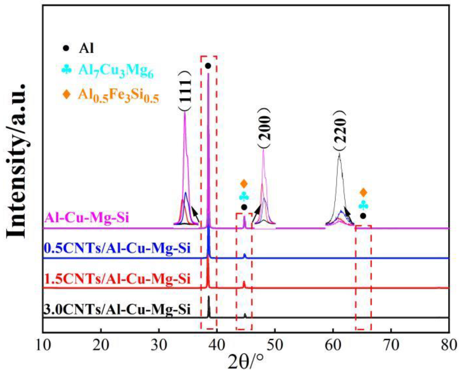
Figure 4 exhibits the XRD patterns of the hot-extruded Al-Cu-Mg-Si alloy materials and CNTs/Al-Cu-Mg-Si composites with different contents of CNTs. The results demonstrated that only the α-Al, S(Al7Cu3Mg6), and Fe-rich (Al0.5Fe3Si0.5) were included in both the Al-Cu-Mg alloy and composites. Due to the low content of added CNTs, no diffraction peaks of CNTs were detected. No new phase containing the C element was detected in the composite material, which indicated that the CNTs were well preserved and did not react with the matrix during the preparation process. Compared with the PDF standard peak(PDF#85-1327), the characteristic diffraction peaks of α-Al in the composites tended to shift to larger 2θ positions, according to Bragg’s law, indicating that the addition of CNTs affected the interplanar spacing of the alloys [34]. Additionally, the intensity of the diffraction peaks of the (111) lattice plane decreased significantly with the addition of CNTs, and the intensity ratio of each diffraction peak was close to the standard ratio [35]. It indicates that the addition of CNTs significantly weakens the (111) surface texture of α-Al and reduces the tendency of the preferred orientation of the hot-extruded Al-Cu-Mg-Si alloy. Table 2 shows that with the increase of CNTs, the width at half maximum (FWHM) of each diffraction peak increases, indicating that the addition of CNTs has a significant effect on the grain refinement of Al-Cu-Mg-Si alloys.
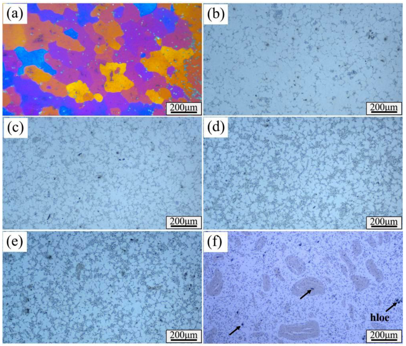
Figure 5 exhibits the radial of x% CNTs/Al-Cu-Mg-Si composites with different mass fractions of CNTs. The hot-extruded Al-Cu-Mg-Si alloy grains are irregular (Figure 5a), and the average grain size is about 150 μm. As the content of CNTs increases, the black phase at the grain boundaries of the composites increases (Figure 5b–f). With the increase in CNTs, the average grain sizes of CNTs/Al-Cu-Mg composites are 36 μm, 28 μm, 24 μm, 23 μm, and 14 μm, respectively.
The experimentally measured densities of all samples are listed in Table 3. The theoretically estimated densities, calculated using the rule of mixture (Equation (1)), are included for comparison purposes.
ρ t h = 1 V C N T ρ A l - C u - M g - S i + V C N T ρ C N T
where ρth is the theoretical density of the composite, ρAl-Cu-Mg-Si is the density of Al-Cu-Mg-Si alloy, ρCNT is the density of the MWCNT (1.9 g/cm3), VCNT is the volume fraction of the CNTs in the composite. The density of the Al-Cu-Mg-Si alloy reaches 99.89%, and there are no significant defects in the structure (Figure 5a), which is close to a completely dense state. With the increase in CNTs, the defects in the composites gradually increase (Figure 5b–f), and the density decreases. The reason is that the CNTs clusters hinder the diffusion of the matrix material during solidification, the wettability of the CNTs and the matrix material is poor, and there are defects between the matrix and the CNTs, resulting in a decrease in the density.
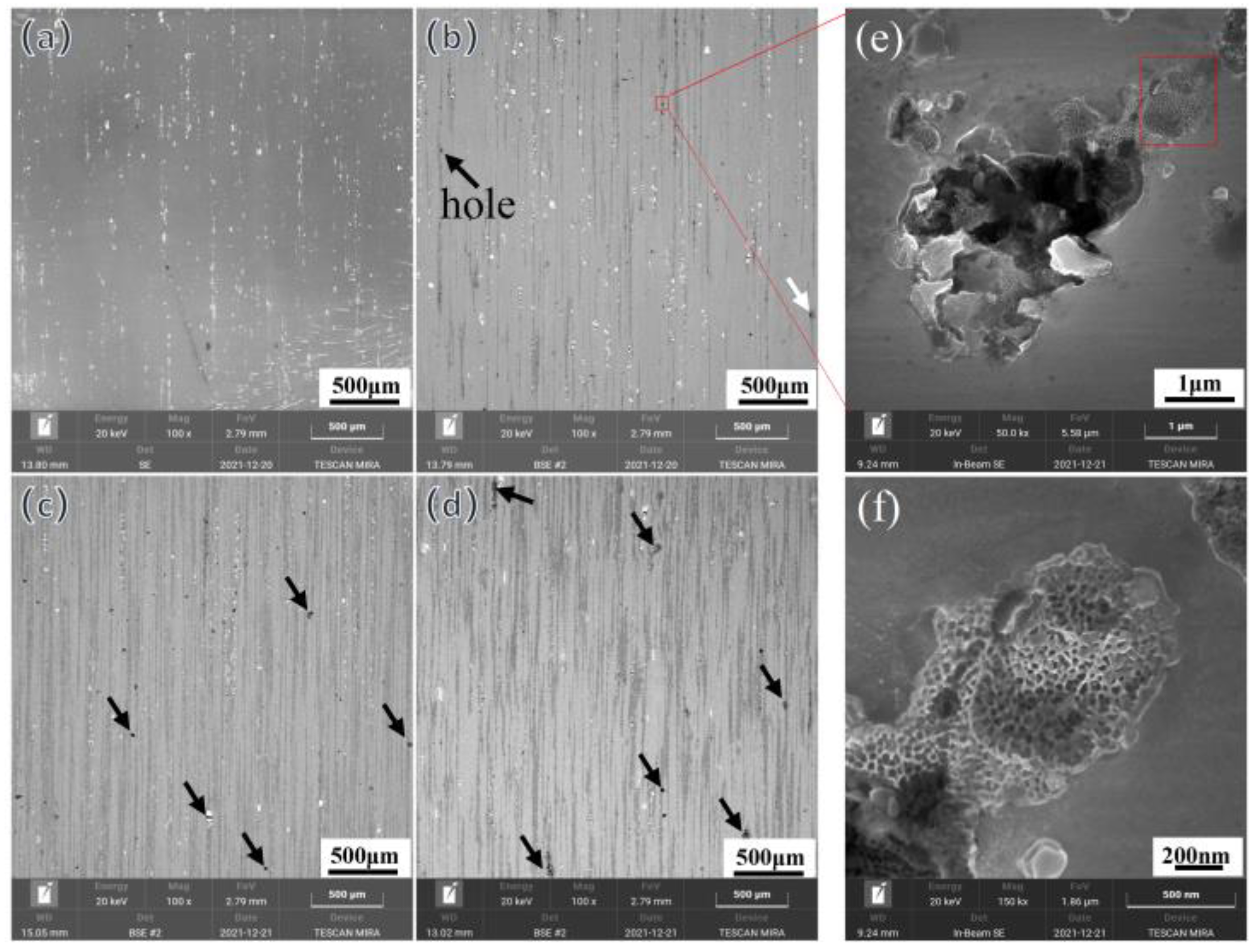
Figure 6 illustrates the microstructure of the 1.5 wt% CNT/Al-Cu-Mg composite along the extrusion direction. The black phase distributed at the grain boundary in Figure 6a,b is mainly the C element, and the positions of the Si element and Fe element are basically coincident, corresponding to the Fe-rich (Al0.5Fe3Si0.5) phase detected by XRD. The microscopic morphology of the CNTs/Al-Cu-Mg-Si composite after deep etching is illustrated in Figure 7. With the increase of CNTs, the holes in the composite gradually increase (Figure 7a–d), which is consistent with the density change in Table 3. A large number of CNTs are distributed around the hole, and there are CNTs entangled clusters (Figure 7e,f).
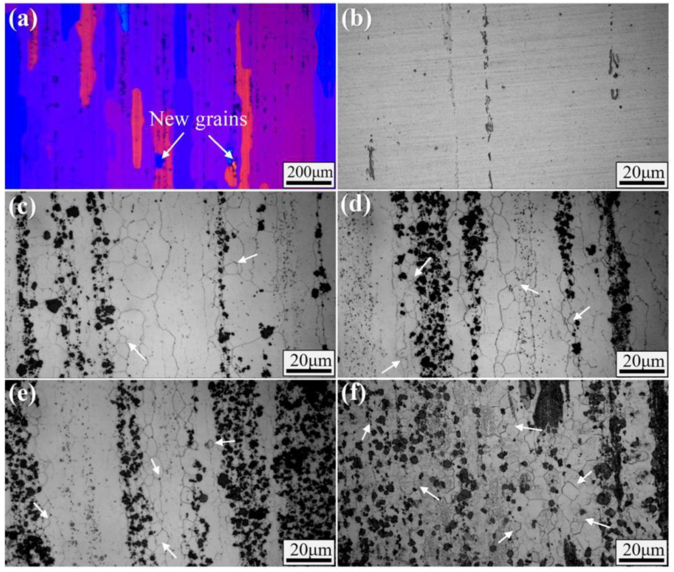
Figure 8 exhibits the microstructures along the extrusion direction of CNTs/Al-Cu-Mg-Si composites with different CNTs mass fractions. It can be observed that the microstructure of the Al-Cu-Mg-Si alloy is streamlined (Figure 8a,b) with a large number of deformed fibrous structures and inconspicuous grain boundaries. Moreover, dynamic recrystallization occurs in the local area, forming fine new grains (indicated by the arrow in Figure 8a) with a volume fraction of about 1.3%. With the increase in CNTs, the number of new grains near the grain boundaries of the original fiber structure gradually increases, and the grain boundaries become clearer, suggesting that the degree of dynamic recrystallization increases. When 1.0 wt% and 1.5 wt% CNTs are added, the corresponding volume fraction of dynamic recrystallization increases to 10.3% and 23.4%, respectively. At this time, the deformed fiber structure still dominates, and the new grains are distributed along the grain boundaries of the fiber structure in a zigzag shape. When the content of CNTs is added to 3 wt%, the volume fraction of recrystallized grains increases to 68.3%, the dynamically recrystallized grains merge and grow, and the fiber structure disappears.
The above results show that with the increase of CNTs content, the dynamic recrystallization degree of hot-extruded Al-Cu-Mg-Si alloy gradually increases, and the volume fraction of recrystallized grains increases from 1.3% to 68.3%. During hot extrusion, the high density of dislocations is the main driving force for inducing dynamic recrystallization. In general, the force P for recrystallization of the extruded metal is calculated using the following [36]:
P = G b 2 N 1 N 2
where G is the shear modulus, b is the Burgers vector, N1 is the dislocation density in the deformed crystal, and N2 is the dislocation density in the fully annealed crystal. For the Al-Cu-Mg-Si alloy without CNTs added, due to the high stacking fault energy, the spacing between the stacking fault distinguishing dislocations is small, and it is easy to bundle and cross-slip [37]. During thermal deformation, the generation of a large number of vacancies in the metal is more conducive to the cross-slip and climbing of dislocations, making it easier for dislocations of opposite signs to meet and disappear, thereby reducing the dislocation density N1. Therefore, the hot-extruded Al-Cu-Mg-Si alloy is prone to dynamic recovery and is not prone to dynamic recrystallization. With the increase of CNTs, the degree of recrystallization in the Al-Cu-Mg-Si alloy increases significantly, which is mainly caused by the following: (1) The thermal expansion coefficients of CNTs and Al are quite different (1.1 × 10⁻⁶ K−1 [12] for CNTs and 23.3 × 10⁻⁶ K−1 [12] for Al). During solidification, the thermal deformation of CNTs and Al is inconsistent, resulting in thermal residual stress in the surrounding matrix of CNTs, inducing a large number of dislocations and increasing the dislocation density N1. (2) The CNTs distributed at the grain boundary have a significant pinning effect on dislocations, affecting the slip and climbing of dislocations, and dislocations are prone to accumulation around them, which is conducive to dynamic recrystallization nucleation.
The Vickers hardnesses of x wt% CNTs/Al-Cu-Mg-Si composites before and after T6 heat treatment are provided in Figure 9. The mechanical properties of the composites increase with the increase in CNTs content. It can be observed that the addition of 3.0 wt% of CNTs increases the hardness in 60 units, reflecting an increment of 61.7% over the Al-Cu-Mg-Si alloy.
The proportional increase in hardness as a function of CNT content can be the result of several strengthening mechanisms [13], such as (1) dislocation strengthening, (2) Orowan strengthening, and (3) a strong interaction between Al and CNTs due to the presence of a transition layer between the intercalation of Al and CNTs sections. The results above demonstrate that the HEBM followed by semi-solid stirring casting is an effective route for the production CNTs/Al composites.

3.2. Tribological Behavior of CNTs/Al-Cu-Mg-Si Nanocomposites

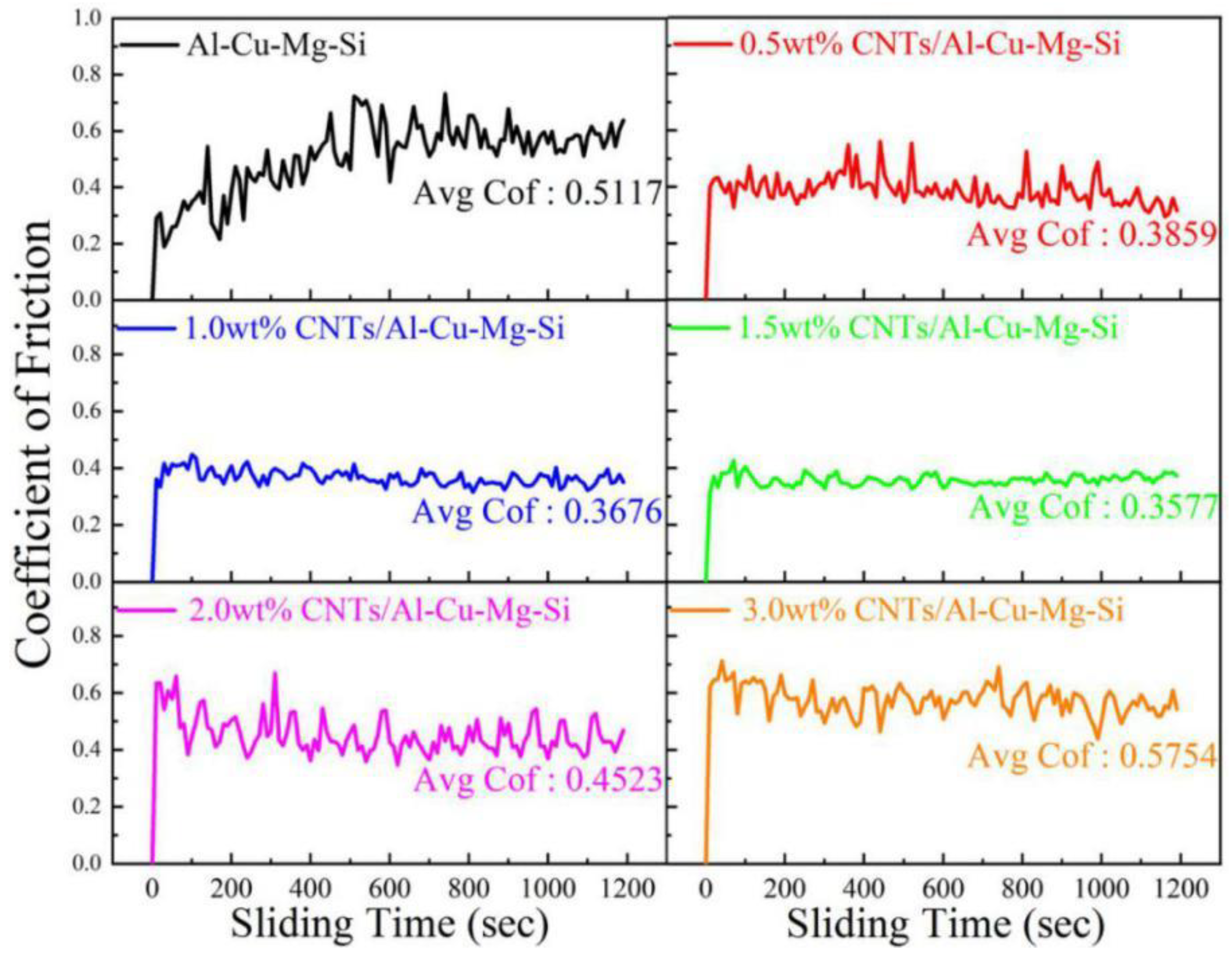
Figure 10 illustrates the COF of the Al-Cu-Mg-Si and CNTs/Al-Cu-Mg-Si composite samples during sliding at a sliding speed of 0.24 m/s under an applied load of 20 N at 20 °C. The friction coefficient curve of Al-Cu-Mg-Si alloy significantly fluctuates, the fluctuation range is about 0.4, and the average friction coefficient is 0.5117. With the increase in CNTs content, the fluctuation range of the friction coefficient curve of CNTs/Al-Cu-Mg-Si composites decreases. When the content of CNTs is 1.5 wt%, the friction coefficient fluctuation range is the smallest (about 0.08), and the average friction coefficient is 0.3577. When the content of CNTs exceeds 2 wt%, the average friction coefficient and the friction coefficient fluctuation range significantly increase. Similar observations were reported by Kim et al. [22], who attributed the reduction in the coefficient of friction to the self-lubricating effects of the CNTs. Generally, a film of carbon can cover the wear surface and act as a solid lubricant that decreases the coefficient of friction.
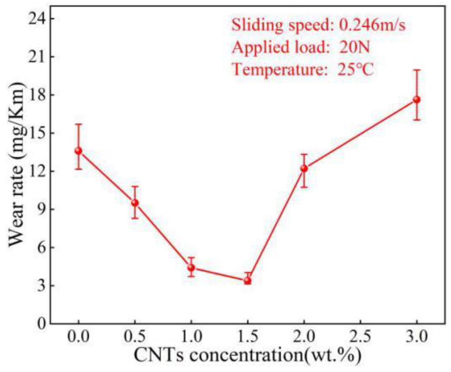
Figure 11 presents the relationship between the wear rate of CNTs/Al-Cu-Mg-Si composites and the content of CNTs. The wear rate of the Al-Cu-Mg-Si alloy is 12.68 mg/Km, and the wear of the composites decreases first and then increases with the increase of CNTs. The wear rate of the composite reaches a minimum value of 3.42 mg/Km at 1.5 wt% CNTs, which is 73.03% lower than that of the Al-Cu-Mg-Si alloy. It is attributed to the strengthening of the Al-Cu-Mg-Si alloy by the CNTs reinforcements, the significant increase in hardness, as presented in Figure 9, as well as the decrease in the coefficient of friction, as shown in Figure 10. When the content of CNTs exceeds 1.5 wt%, the wear rate of the composites rebounds. This can be attributed to CNTs agglomeration, which results in pores, poor densification, and the consequent separation of conglomerated particles that weakly bond to the surface.
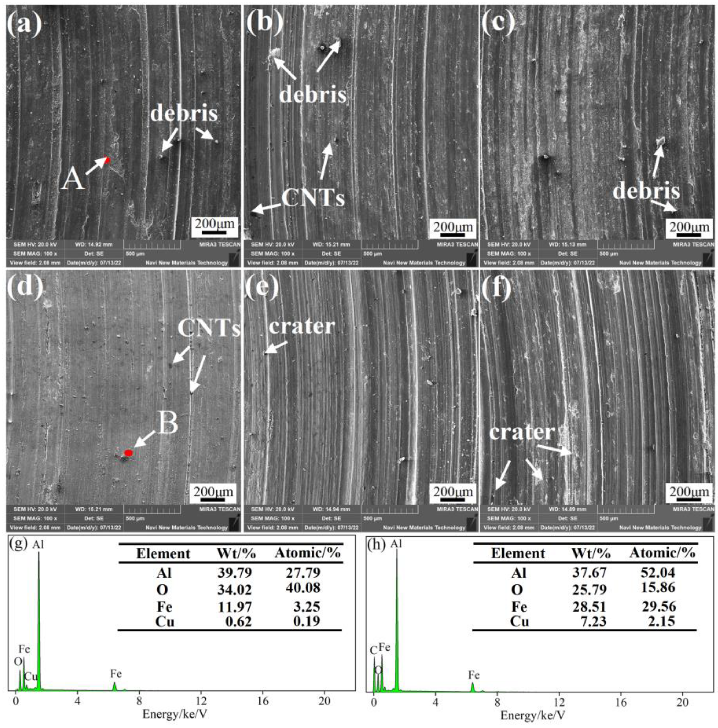
Figure 12 demonstrates SEM micrographs and EDS of the worn surfaces of the Al-Cu-Mg-Si and CNTs/Al-Cu-Mg-Si composite samples. The friction surface of the Al-Cu-Mg-Si alloy sample is delaminated (Figure 12a), and large pieces of material peel off from the surface of the substrate, leaving deep and wide furrows on the friction surface. This reflects noticeable plastic deformation and delamination wear. Compared with the Al-Cu-Mg-Si alloy, the plastic deformation tendency of the CNTs/Al-Cu-Mg-Si composite is significantly reduced (Figure 12b–f). The analysis of the worn surface of the 0.5 wt%CNTs/Al-Cu-Mg-Si composite sample reveals less severe scars and material delamination compared to the Al-Cu-Mg-Si alloy. A clear change in the wear mechanism is observed as the content of CNTs increases to 1.5 wt%. The dominant wear mechanism changed from adhesive wear (Al-Cu-Mg-Si alloy) to abrasive wear (1.5 wt%CNT), generating smoother surfaces. When the content of CNTs exceeds 1.5 wt%, the furrows on the wear surface are densely distributed, manifesting severe abrasive wear. As noted earlier, as the CNTs increased in the composites, the grain refinement effect was significant, and the hardness of the composite increased, which limited the plastic deformation of the surface. Additionally, CNTs have excellent physical properties, lessen the direct contact area between the aluminum matrix and the friction disc (Figure 12h), and significantly lower the friction coefficient due to the self-lubricating properties of CNTs [35].
Figure 13 presents the COF of x% CNTs /Al-Cu-Mg-Si samples. At 200 °C, the average friction coefficient of the composites first decreases and then increases with the increase in the content of CNTs, consistent with the friction law at 20 °C. Notably, the friction coefficient of x% CNTs /Al-Cu-Mg-Si composites fluctuates drastically at 200 °C, and the average friction coefficient is lower than at 20 °C. As the temperature increases, the viscosity of the base alloy increases, and softening occurs, leading to a decrease in frictional resistance. Concurrently, a large amount of wear debris accumulates on the friction surface and is repeatedly rolled into the pits of the wear scar. This plays a lubricating role and lowers the friction coefficient.
Figure 14 exhibits the wear rate of x% CNTs /Al-Cu-Mg-Si composites at 200 °C. Compared with the Al-Cu-Mg-Si alloy, the wear rate of the composites is significantly reduced. The reasons are detailed as follows. (1) At high temperatures, the plastic deformation and high-temperature softening of the aluminum matrix are intensified, and the strength and hardness of the material are considerably curtailed, aggravating cutting and adhesive wear. The addition of CNTs strengthens the matrix material, constrains the softening and plastic deformation of the matrix at high temperatures, inhibits material shedding, and lessens the wear rate. (2) The self-lubricating properties and excellent thermal conductivity of CNTs help to reduce and release the heat generated during the sliding process.
Figure 15 displays SEM micrographs of the worn surfaces of the Al-Cu-Mg-Si and CNTs/Al-Cu-Mg-Si composite samples at 200 °C. The wear surface of Al-Cu-Mg-Si alloy has shallow furrows and remarkable adhesion and detachment area (Figure 15a), demonstrating severe plastic deformation and adhesion wear. The plastic deformation of the composites weakens with the increase in the content of CNTs. There are a few shallow furrows in the composite and very few sticking areas, which are light wear (Figure 15d). When the content of CNTs exceeds 1.5 wt%, the wear is aggravated, the furrow is deepened, and partial shedding areas emerge on both sides of the furrow, while there is no typical adhesive wear phenomenon.

4. Conclusions

In this study, CNTs-reinforced Al-Cu-Mg-Si nanocomposites were successfully fabricated by HEBM combined with semi-solid stir casting. The microstructure and tribological behavior were characterized and compared with pure Al-Cu-Mg-Si specimens. The conclusions are drawn as follows.
(1)
CNTs can pin the grain boundaries, hinder grain growth, and significantly refine the a-Al phase. As the content of CNTs increased from 0 to 3.0 wt%, the average grain diameter decreased from 150μm to 14μm. The addition of CNTs can considerably reduce the preferred orientation of the α-Al phase on the (111) lattice plane.
(2)
With the increase in the content of CNTs, the hardness of the hot-extruded CNTs/Al-Cu-Mg-Si composite significantly increased. Moreover, the hardness increased by 62.2% compared with the Al-Cu-Mg-Si alloy when 3.0 wt% CNTs were added, reaching 157.7 HV.
(3)
With the increase in the content of CNTs, the degree of dynamic recrystallization of Al-Cu-Mg-Si alloy in hot extrusion gradually increased, the volume fraction of recrystallized grains increased from 1.3% to 68.3%, and the grain boundaries became clearer.
(4)
The friction and wear properties of x% CNTs/Al-Cu-Mg-Si composites suggested that the friction coefficient and wear rate of the composites at 20 °C and 200 °C both decreased first and then increased with the increase in the content of CNTs. When the CNTs content was 1.5 wt%, the wear resistance of the composite was the best at 20 °C and 200 °C, and the COF was 30.09% and 73.03% lower than that of the Al-Cu-Mg-Si alloy. The main wear mechanism changed from adhesive wear to abrasive wear.

Author Contributions

Conceptualization, Z.Z.; methodology, Y.L.; investigation, F.T.; data curation, K.L.; writing—original draft preparation, L.W.; writing—review and editing, Y.X. All authors have read and agreed to the published version of the manuscript.

Funding

This research was funded by The science and technology innovation Program of Hunan Province, grant number [2022RC1056].

Institutional Review Board Statement

Not applicable.

Informed Consent Statement

Not applicable.

Data Availability Statement

Not applicable.

Conflicts of Interest

The authors declare no conflict of interest.

References

  1. Trojanowicz, M. Analytical applications of carbon nanotubes: A review. Trends Anal. Chem. 2006, 25, 480–489. [Google Scholar] [CrossRef]
  2. Deng, C.; Zhang, X.; Wang, D.; Lin, Q.; Li, A. Preparation and characterization of carbon nanotubes/aluminum matrix composites. J. Shenyang Univ. 2013, 61, 1725–1728. [Google Scholar] [CrossRef]
  3. Nam, D.H.; Kim, J.H.; Cha, S.I.; Jung, S.I.; Lee, J.K.; Park, H.M.; Park, H.D.; Hong, S.H. Hardness and Wear Resistance of Carbon Nanotube Reinforced Aluminum-Copper Matrix Composites. J. Nanosci. Nanotechnol. 2014, 14, 9134–9138. [Google Scholar] [CrossRef]
  4. Ostovan, F.; Matori, K.A.; Toozandehjani, M.; Oskoueian, A.; Yusoff, H.M.; Yunus, R.; Mohamed Ariff, A.H. Nanomechanical Behavior of Multi-Walled Carbon Nanotubes Particulate Reinforced Aluminum Nanocomposites Prepared by Ball Milling. Materials 2016, 9, 140. [Google Scholar] [CrossRef] [PubMed] [Green Version]
  5. Zhang, H.B.; Wang, B.; Zhang, Y.T.; Li, Y.; He, J.L.; Zhang, Y.F. Influence of aging treatment on the microstructure and mechanical properties of CNTs/7075 Al composites. J. Alloys Compd. 2019, 814, 152357. [Google Scholar] [CrossRef]
  6. Yu, T.; Liu, J.; He, Y.; Tian, J.; Chen, M.; Wang, Y. Microstructure and wear characterization of carbon nanotubes (CNTs) reinforced aluminum matrix nanocomposites manufactured using selective laser melting—ScienceDirect. Wear 2020, 476, 203581. [Google Scholar] [CrossRef]
  7. Huang, Y.; Li, J.; Wan, L.; Meng, X.; Xie, Y. Strengthening and toughening mechanisms of CNTs/Mg-6Zn composites via friction stir processing. Mater. Sci. Eng. A 2018, 732, 205–211. [Google Scholar] [CrossRef]
  8. Pérez-Bustamante, R.; Pérez-Bustamante, F.; Maldonado-Orozco, M.C.; Martínez-Sánchez, R. The effect of heat treatment on microstructure evolution in artificially aged carbon nanotube/Al2024 composites synthesized by mechanical alloying. Mater. Charact. 2017, 126, 28–34. [Google Scholar] [CrossRef]
  9. Duan, B.; Zhou, Y.; Wang, D.; Zhao, Y. Effect of CNTs content on the microstructures and properties of CNTs/Cu composite by microwave sintering. J. Alloys Compd. 2018, 771, 498–504. [Google Scholar] [CrossRef]
  10. Xiong, N.; Bao, R.; Yi, J.; Tao, J.; Liu, Y.; Fang, D. Interface evolution and its influence on mechanical properties of CNTs/Cu-Ti composite. Mater. Sci. Eng. A 2019, 755, 75–84. [Google Scholar] [CrossRef]
  11. Ma, G.; Li, L.; Xi, S.; Xiao, Y.; Li, Y.; Yuan, Z.; He, Y.; Zhou, R.; Jiang, Y. Enhanced combination of strength and ductility in the semi-solid rheocast hypereutectic Al Si alloy with the effect of in-situ TiB2 particles. Mater. Charact. 2021, 176, 111143. [Google Scholar] [CrossRef]
  12. Zhang, Z.; Xiao, Y.; Xu, J.; He, M.; Luo, Y.; Xiang, J. Understanding the Influencing Mechanism of Cnts on the Microstructure and Mechanical Properties of Semi-Solid Stir Casting Al-Cu-Mg Alloys; Social Science Electronic Publishing: Rochester, NY, USA, 2022. [Google Scholar]
  13. Nam, D.H.; Cha, S.I.; Lim, B.K.; Park, H.M.; Han, D.S.; Hong, S.H. Synergistic strengthening by load transfer mechanism and grain refinement of CNT/Al–Cu composites. Carbon 2012, 50, 2417–2423. [Google Scholar] [CrossRef]
  14. Li, S.; Han, Y.; Shi, Z.; Huang, G.; Zong, N.; Le, J.; Qiu, P.; Lu, W. Synergistic strengthening behavior and microstructural optimization of hybrid reinforced titanium matrix composites during thermomechanical processing—ScienceDirect. Mater. Charact. 2020, 168, 110527. [Google Scholar] [CrossRef]
  15. Liang, J.; Li, H.; Qi, L.; Tian, W.; Li, X.; Chao, X.; Wei, J. Fabrication and mechanical properties of CNTs/Mg composites prepared by combining friction stir processing and ultrasonic assisted extrusion. J. Alloys Compd. 2017, 728, 282–288. [Google Scholar] [CrossRef]
  16. Du, Z.L.; Tan, M.J.; Guo, J.F.; Wei, J.; Chua, C.K. Dispersion of CNTs in Selective Laser Melting Printed AlSi10Mg Composites via Friction Stir Processing. Mater. Ence Forum 2016, 879, 1915–1920. [Google Scholar] [CrossRef]
  17. Li, C.D.; Wang, X.J.; Liu, W.Q.; Shi, H.L.; Ding, C.; Hu, X.S.; Zheng, M.Y.; Wu, K. Effect of solidification on microstructures and mechanical properties of carbon nanotubes reinforced magnesium matrix composite. Mater. Des. 2014, 58, 204–208. [Google Scholar] [CrossRef]
  18. Chen, B.; Kondoh, K.; Li, J.S.; Qian, M.J.C.P.B.E. Extraordinary reinforcing effect of carbon nanotubes in aluminium matrix composites assisted by in-situ alumina nanoparticles. Composites 2020, 183, 107691.1–107691.11. [Google Scholar] [CrossRef]
  19. Li, C.D.; Wang, X.J.; Wu, K.; Liu, W.Q.; Xiang, S.L.; Ding, C.; Hu, X.S.; Zheng, M.Y. Distribution and integrity of carbon nanotubes in carbon nanotube/magnesium composites. J. Alloys Compd. 2014, 612, 330–336. [Google Scholar] [CrossRef]
  20. Kim, I.Y.; Lee, J.H.; Lee, G.S.; Baik, S.H.; Kim, Y.J.; Lee, Y.Z. Friction and wear characteristics of the carbon nanotube-aluminum composites with different manufacturing conditions. Wear 2009, 267, 593–598. [Google Scholar] [CrossRef]
  21. Chen, B.; Kondoh, K.; Imai, H.; Umeda, J.; Takahashi, M. Simultaneously enhancing strength and ductility of carbon nanotube/aluminum composites by improving bonding conditions. Scr. Mater. 2016, 113, 158–162. [Google Scholar] [CrossRef]
  22. Basariya, M.R.; Srivastava, V.C.; Mukhopadhyay, N.K. Microstructural characteristics and mechanical properties of carbon nanotube reinforced aluminum alloy composites produced by ball milling. Mater. Des. 2014, 64, 542–549. [Google Scholar] [CrossRef]
  23. Maqbool, A.; Hussain, M.A.; Khalid, F.A.; Bakhsh, N.; Hussain, A.; Kim, M.H. Mechanical characterization of copper coated carbon nanotubes reinforced aluminum matrix composites. Mater. Charact. 2013, 86, 39–48. [Google Scholar] [CrossRef]
  24. Nam, D.H.; Kim, Y.K.; Cha, S.I.; Hong, S.H. Effect of CNTs on precipitation hardening behavior of CNT/Al–Cu composites. Carbon 2012, 50, 4809–4814. [Google Scholar] [CrossRef]
  25. Guo, B.; Chen, Y.; Wang, Z.; Yi, J.; Ni, S.; Du, Y.; Li, W.; Song, M. Enhancement of strength and ductility by interfacial nano-decoration in carbon nanotube/aluminum matrix composites. Carbon 2019, 159, 201–212. [Google Scholar] [CrossRef]
  26. Ma, K.; Zhang, X.; Wang, D.; Wang, Q.; Liu, Z.; Xiao, B.; Ma, Z. Optimization and simulation of deformation parameters of SiC/2009Al composites. Acta Metall. Sin. 2019, 55, 1329–1337. [Google Scholar]
  27. Guo, B.; Zhang, X.; Cen, X.; Chen, B.; Wang, X.; Song, M.; Ni, S.; Yi, J.; Shen, T.; Du, Y. Enhanced mechanical properties of aluminum based composites reinforced by chemically oxidized carbon nanotubes. Carbon 2018, 139, 459–471. [Google Scholar] [CrossRef]
  28. Xiao, P.; Gao, Y.; Xu, F.; Yang, S.; Li, B.; Li, Y.; Huang, Z.; Zheng, Q. An investigation on grain refinement mechanism of TiB2 particulate reinforced AZ91 composites and its effect on mechanical properties. J. Alloys Compd. 2019, 780, 237–244. [Google Scholar] [CrossRef]
  29. Toozandehjani, M.; Matori, K.A.; Ostovan, F.; Jamaludin, K.R.; Amrin, A.; Shafiei, E. The Effect of the Addition of CNTs on the Microstructure, Densification and Mechanical Behavior in Al-CNT-Al2O3 Hybrid Nanocomposites. JOM J. Miner. Met. Mater. Soc. 2020, 72, 2283–2294. [Google Scholar] [CrossRef]
  30. Li, Y.; Xi, S.; Ma, G.; Xiao, Y.; Li, L.; Yuan, Z.; He, Y.; Zhou, R.; Jiang, Y. Understanding the influencing mechanism of sub-micron sized TiB 2p on the microstructures and properties of rheological squeeze casting hypereutectic Al–Si alloys. J. Mater. Res. Technol. 2021, 14, 57–68. [Google Scholar] [CrossRef]
  31. Hu, X.G.; Zhu, Q.; Lu, H.X.; Zhang, F.; Li, D.Q.; Midson, S.P. Microstructural evolution and thixoformability of semi-solid aluminum 319s alloy during re-melting. J. Alloys Compd. 2015, 649, 204–210. [Google Scholar] [CrossRef]
  32. Al-Qutub, A.M.; Khalil, A.; Saheb, N.; Hakeem, A.S. Wear and friction behavior of Al6061 alloy reinforced with carbon nanotubes. Wear 2013, 297, 752–761. [Google Scholar] [CrossRef]
  33. Nardone, V.C.; Prewo, K.M. On the strength of discontinuous silicon carbide reinforced aluminum composites. Scr. Metall. 1986, 20, 43–48. [Google Scholar] [CrossRef]
  34. Gu, D.; Rao, X.; Dai, D.; Ma, C.; Xi, L.; Lin, K. Laser additive manufacturing of carbon nanotubes (CNTs) reinforced aluminum matrix nanocomposites: Processing optimization, microstructure evolution and mechanical properties. Addit. Manuf. 2019, 29, 100801. [Google Scholar] [CrossRef]
  35. Liu, X.; Liu, E.; Li, J.; He, C.; Zhao, N. Investigation of the evolution and strengthening effect of aluminum carbide for in-situ preparation of carbon nanosheets/aluminum composites. Mater. Sci. Eng. 2019, 764, 138139.1–138139.8. [Google Scholar] [CrossRef]
  36. Zhang, T.; Feng, K.; Li, Z.; Kokawa, H. Effects of in-situ synthesized TiB2 on crystallographic orientation, grain size and nanohardness of AA6061 alloy by laser surface alloying. Mater. Lett. 2019, 253, 213–217. [Google Scholar] [CrossRef]
  37. Xi, S.; Ma, G.; Li, L.; Li, Y.; Zhou, R.; Jiang, Y. Investigate on the phase interfaces and performance evaluation of TiB2p/Al-Si-Cu-Zn (T6) composites. J. Mater. Res. Technol. 2021, 12, 581–596. [Google Scholar] [CrossRef]
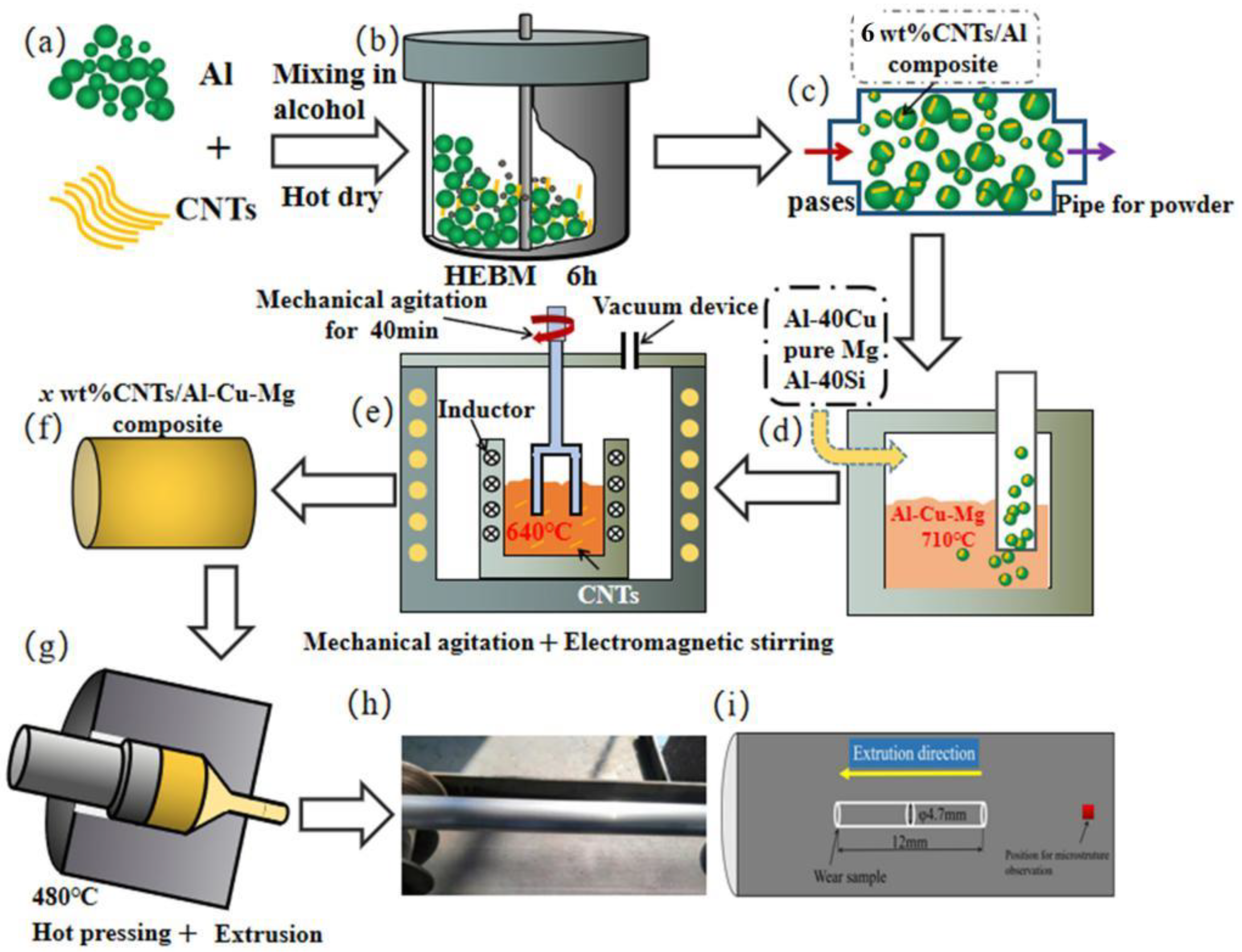
Figure 1. (ai) Schematic diagram of preparation route for x% CNTs/Al-Cu-Mg-Si composites and semi-solid stir casting.
Metals 12 02171 g001
Figure 2. The microstructure and phase composition of raw powders. (a,b) CNTs; (c) XRD patterns of CNTs.
Metals 12 02171 g002
Figure 3. The microstructure and phase composition of milled CNTs/Al nanocomposites powders. (a,b) CNTs/Al; (c) XRD patterns of CNTs/Al.
Metals 12 02171 g003
Figure 4. XRD patterns of CNTs/Al-Cu-Mg-Si composites.
Metals 12 02171 g004
Figure 5. OM image. (a) Al-Cu-Mg-Si alloy; (b) 0.5 wt% CNTs/Al-Cu-Mg-Si composites; (c) 1.0 wt% CNTs/Al-Cu-Mg-Si composites; (d) 1.5 wt% CNTs/Al-Cu-Mg-Si composites; (e) 2.0 wt% CNTs/Al-Cu-Mg-Si composites; (f) 3.0 wt% CNTs/Al-Cu-Mg-Si composites.
Metals 12 02171 g005
Figure 6. Microstructure of as hot-extrusion 1.5 wt% CNT/Al-Cu-Mg-Si composite. (a) OM image of macrostructure, (bh) SEM back-scattered electron image (Determine the distribution of C, Al, Si, Fe, Cu, Mg by scanning the EDS surface).
Metals 12 02171 g006
Figure 7. SEM image of x% CNTs/Al-Cu-Mg-Si composites. (a) Al-Cu-Mg-Si alloy; (b) 1.5 wt% CNTs/Al-Cu-Mg-Si composites; (c) 2.0 wt% CNTs/Al-Cu-Mg-Si composites; (d) 3.0 wt% CNTs/Al-Cu-Mg-Si composites; (e,f) High magnification morphology at holes.
Metals 12 02171 g007
Figure 8. Microstructures along the extrusion direction. (a) Al-Cu-Mg-Si alloy; (b) 0.5 wt% CNTs/Al-Cu-Mg-Si composites; (c) 1.0 wt % CNTs/Al-Cu-Mg-Si composites; (d) 1.5 wt % CNTs/Al-Cu-Mg-Si composites; (e) 2.0 wt % CNTs/Al-Cu-Mg-Si composites; (f) 3.0 wt % CNTs/Al-Cu-Mg-Si composites.
Metals 12 02171 g008
Figure 9. Results from the microhardness test of CNTs/Al-Cu-Mg-Si composites.
Metals 12 02171 g009
Figure 10. Plot of the coefficient of friction as a function of sliding time for. x wt%CNTs /Al-Cu-Mg-Si composites at 20 °C.
Metals 12 02171 g010
Figure 11. Wear rate versus CNT wt%.
Metals 12 02171 g011
Figure 12. SEM micrographs and EDS of representative worn surfaces of x% CNTs/Al-Cu-Mg-Si: (a) 0 wt%, (b) 0.5 wt%, (c) 1.0 wt%, (d) 1.5 wt%, (e) 2.0 wt%, (f) 3.0 wt%, (g) EDS result of point A, (h) EDS result of point B.
Metals 12 02171 g012
Figure 13. Plot of the coefficient of friction as a function of sliding time for x% CNTs /Al-Cu-Mg-Si composites under 200 °C.
Metals 12 02171 g013
Figure 14. Wear rate of the x% CNTs /Al-Cu-Mg-Si composites under 200 °C.
Metals 12 02171 g014
Figure 15. SEM micrographs of representative worn surfaces of x% CNTs /Al-Cu-Mg-Si under 200 °C: (a) 0 wt%, (b) 0.5 wt%, (c) 1.0 wt%, (d) 1.5 wt%, (e) 2.0 wt%, (f) 3.0 wt%. (g) EDS result of point A, (h) EDS result of point B.
Metals 12 02171 g015
Table 1. Chemical compositions of the experimental materials (wt%).
Experimental MaterialCCuMgSiFeAl
6 wt%CNTs/Al composite6.231000.0370.598Balance
Al-Cu-Mg-Si alloy0.0121.4370.8340.9420.014Balance
0.5 wt%CNTs/Al-Cu-Mg-Si composite 0.4921.3240.7800.8970.275Balance
1.0 wt%CNTs/Al-Cu-Mg-Si composite1.0141.3680.7630.9130.304Balance
1.5 wt%CNTs/Al-Cu-Mg-Si composite1.4421.4020.8020.9240.387Balance
2.0 wt%CNTs/Al-Cu-Mg-Si composite1.9171.4360.8140.8730.395Balance
3.0 wt%CNTs/Al-Cu-Mg-Si composite2.8431.3160.7960.8910.420Balance
Table 2. XRD data showing the intensity variation of the identified peaks for Al phase in the CNTs/Al-Cu-Mg-Si composite.
XRD
Parameters
StandardAl-Cu-Mg-Si Alloy0.5CNTs/Al-Cu-Mg-Si1.5CNTs/Al-Cu-Mg-Si3.0CNTs/Al-Cu-Mg-Si
2θ (deg.) (111)38.47438.4861538.5124138.3942438.49302
Intensity (CPS)1001,039,711296,694227,3508282
FWHM (deg.) 0.1410.1670.1690.224
2θ (deg.) (200)44.72244.709944.7361644.6573844.72303
Intensity (CPS)45.580,28528,00143,7534277
FWHM(deg.) 0.1710.1760.2280.257
2θ (deg.) (220)65.09965.0487165.1668965.0618465.11436
Intensity (CPS)23.31533952211727
FWHM (deg.) 0.4600.4480.4290.346
Table 3. The density of x CNTs/Al-Cu-Mg-Si composites.
MaterialTheoretical Density
(g/cm3)
Relative Density
(g/cm3)
Density
(%)
Al-Cu-Mg-Si alloy2.7692.76699.89
0.5CNTs/Al-Cu-Mg-Si composite2.7662.75999.74
1.0CNTs/Al-Cu-Mg-Si composite2.7622.74899.49
1.5CNTs/Al-Cu-Mg-Si composite2.7592.73899.24
2.0CNTs/Al-Cu-Mg-Si composite2.7562.71998.66
3.0CNTs/Al-Cu-Mg-Si composite2.7492.67097.13
Publisher’s Note: MDPI stays neutral with regard to jurisdictional claims in published maps and institutional affiliations.