Article

Repair Reliability Analysis of a Special-Shaped Epoxy Steel Sleeve for Low-Strength Tee Pipes

1
State Key Laboratory of Performance and Structural Safety for Petroleum Tubular Goods and Equipment Materials, CNPC Tubular Goods Research Institute, Xi’an 710077, China
2
Pipeline Network Group (Xinjiang) United Pipeline Co., Ltd., Urumqi 830012, China
3
School of Materials Science and Engineering, Xi’an University of Technology, Xi’an 710048, China
*
Author to whom correspondence should be addressed.
Metals 2022, 12(12), 2149; https://doi.org/10.3390/met12122149
Submission received: 6 November 2022 / Revised: 8 December 2022 / Accepted: 12 December 2022 / Published: 14 December 2022
(This article belongs to the Special Issue Deformation, Fracture and Microstructure of Metallic Materials)

Abstract

:
Ensuring the safe operation of pipe fittings in a natural gas station is critical. The irregular shape of the tee easily leads to uneven mechanical properties in the manufacturing process. The strength of the tee may be lower than the requirements due to its unqualified heat-treatment process. As a result, selecting a reliable way of repairing low-strength tee pipes is a pressing concern. To repair the low-strength tee pipes, a special-shaped epoxy steel sleeve (SSESS) was designed. To optimize the critical design parameters, the SSESS design criteria were established. Following that, the SSESS repair testing was conducted using the optimized design parameters. The SSESS repair reliability was proved using hydraulic burst testing with strain monitoring and simulations of unrepaired and SSESS repaired tees. The result indicated that the SSESS repaired tee’s yielding and burst pressure increased, demonstrating its repair reliability. Furthermore, the SSESS repair revealed the stress and strain concentration decrease law.

Graphical Abstract

1. Introduction

The irregular shape of a large diameter tee pipe is an important aspect of oil and gas transmission pipeline engineering, but it can easily cause unequal performance during the production process. The mechanical characteristics of the large-diameter tee in batches might not fully meet the technical criteria during the heat treatment process of the tee due to numerous causes, such as the irregularity of the tee structure and the non-strict implementation of the heat treatment procedure [1]. Some unqualified tees are not screened out by performance sampling due to the latency of performance non-destructive testing procedures. In addition, irregularly shaped tees inherently suffer from local plastic deformation during the pressure-bearing process [2]. As a result, an issue has been proposed: how to cope with in-service unqualified strength tee.
If a type-B sleeve [3,4] or a special-shaped type-B sleeve [5], is used in a natural gas station, pressure reduction and welding are necessary. However, shutting down the station and dealing with the on-site welding process is challenging. Although the composite repair is simple [6], there are issues with the tee’s abdominal winding, which is insufficient for mending the tee’s unique shape. The composite’s aging problem cannot be remedied [7,8], and the low-strength tee cannot be repaired permanently. In addition, a solution involving a steel hose junction was used for the high-pressure hoses and junctions to overcome the external damage [9].
Epoxy sleeve repair (ESR) is distributed by PII [10]. Two steel shells with a slightly larger diameter than the pipeline to be repaired are connected to cover the damaged part of the pipeline. The sleeve is installed on the surface of the pipeline in the field, and the two ends are sealed, and then the epoxy resin is injected to fill the pores between the pipeline and the repaired sleeve. The epoxy grout compound forms an excellent bond at both steel interfaces, providing a high reinforcement of the damaged section, in the axial and circumferential directions. British Gas developed a variation of the sleeve repair concept in the form of their epoxy-filled shell repair [11]. Wood [12] elaborated on the key advantages of ESR in detail. The steel compression sleeves are introduced in the PRCI [4] and CSA Z662 [13], which is similar to the ESR. The defects of the welded joint were repaired by ESR, and proved by numerical simulation [14]. Mazurkiewicz et al. [15] studied the repair reliability of fiber glass sleeves using the burst test, and numerical simulation, and verify selected sleeve thickness. Arif et al. [16] optimized the thickness of the repair sleeve using the failure pressure estimation and simulation of sleeve installation pressure, in 24 cases ranging from 6 to 60 inches, and the optimization approach should approximate the conditions of the tests performed. Recently, Jaszak et al. [17] proposed a methodology of leakage prediction in gasketed flange joints at deformation based on finite element methods by applying a complex and multi-stage method. Li et al. [18] applied a special steel sleeve filled with epoxy resin for the leakage of the welding connection platform on the brine pipeline. However, the special-shaped ESR for the tee was rarely reported.
In this study, a special-shaped epoxy steel sleeve (SSESS) method was proposed to address the low-strength in-service tee pipe. The purpose of this study is to propose an approach to improve safety factor and eliminate potential safety hazards. The SSESS method has two advantages: nonstop transmission and high reliability. The design criteria of SSESS were presented to optimize the critical design parameters. Then, the SSESS test was performed based on the optimization design parameters. Hydraulic burst tests with strain monitoring and simulations of unrepaired and SSESS tees were carried out to prove the repair reliability of the SSESS. According to comparisons of the strain monitoring, simulation, and hydraulic burst curves between unrepaired and SSESS tees, the reliability of the SSESS repaired low-strength tee was verified.

2. Materials and Methods

2.1. Materials Properties

A 1000 mm × 1000 mm × 800 mm tee was detected as unqualified strength of X70 steel by indentation, metallurgic replica, and Leeb hardness technologies. However, the critical tensile properties of the tee were obtained from the tee of the same batch and furnace. The tensile properties of the low-strength tee are listed in Table 1.

2.2. Design of the Special-Shaped Steel Sleeve

The repair process of low strength tee mainly included the special-shaped steel sleeve and the epoxy resin material. The special-shaped steel sleeve is of interest in this study. The special-shaped steel sleeve structure adopted the welding structure. The stress analysis is the theoretical basis for designing the special-shaped steel sleeve. The strength theory’s equivalent stress or stress strength is the failure criterion. Some researchers have also used progressive failure analysis to identify the failure locations in the simulation of composite structures under aeroelastic loading [19]. The design calculation of the steel shell special-shaped epoxy sleeve under the condition of pipeline reinforcement was mainly based on the standard of GB50251-2015 (gas pipeline engineering design). One of the critical parameters of a special-shaped sleeve design was to calculate the wall thickness, which was considered under the designing pressure of 12 MPa.
According to GB50251-2015, the calculation formula for sleeve minimum thickness δ can be given as:
δ = P D 2 σ s φ F t
where P is the designing pressure, D is the outer diameter of the pipe, σ s is the yield strength, φ is the welding parameter, F is the strength design coefficient, t is the temperature reduction coefficient. In this study, a tee with a specification of 1000 mm × 1000 mm × 800 mm was chosen as the test object. In addition, the material of the tee used 16 Mn of its wide applications and low cost. φ and t were set as 1, respectively, and F was set as 0.4. Hence, the minimum δ of the main and branch pipes were calculated as ~44 mm and ~36 mm, respectively. So, the design δ values of the main and branch pipes should be larger than 44 mm and 36 mm, respectively.
Another critical parameter of the SSESS is the length between the edge of the sleeve and the girth weld, as shown in Figure 1. Due to the unequal wall thickness girth weld between the tee and straight pipe, stress concentration is easily formed in the root toe of the girth weld. Therefore, six SSESS repair modes were simulated to repair the low strength 1000 mm × 1000 mm × 800 mm tee. The repair modes of six kinds of SSESS mainly changed the length of L h as −175 mm, −100 mm, 0 mm, 100 mm, 200 mm, and 300 mm, respectively, as shown in Figure 2. According to the simulation results, the yielding pressure could be obtained in every case. The maximum allowance working pressure (MAWP) was calculated based on the strength design coefficient of 0.5, as shown in Figure 3. As shown in Figure 3, the length of L h needs to be larger than 0. The special-shaped sleeve must contain the girth weld to the MAWP larger than the designing pressure of 12 MPa. The MAWP tends to be constant when L h is larger than 100 mm. So, the design value of L h needs to be larger than 100 mm. The design and material grade of equal-length studs and hexagon nuts were based on the standards of GB/T 901 (Equal-length studs) and GB/T 6170 (Hexagon nuts) in China, respectively. The material grade of equal-length studs and hexagon nuts were 10.9 and 10, respectively.
The gap C between the sleeve and tee was set as 25~40 mm, based on the fluidity and solidification time. In addition, the design of the injection and exhaust holes for the special-shaped sleeve should follow a principle, the injection and the exhaust holes need to be designed on the top and bottom of the sleeve, respectively, as shown in Figure 4. The shape and size of the design of an SSESS for 1000 mm × 1000 mm × 800 mm tee is shown in Figure 5. The holes of the positioning bolt need to be designed on the edges of the sleeve, as shown in Figure 5. The bolt fastening is used for the connection of the sleeve, as shown in Figure 5.

2.3. Repairing Test of SSESS

The hydraulic test structural part containing the 1000 mm × 1000 mm × 800 mm tee was welded for repair and hydraulic tests to verify the reliability of the SSESS. The procedures of repair and hydraulic tests were introduced as follows:
  • Step 1: Surface cleaning and sand-blasting
The repairing areas of the outer surface of the hydraulic test structural part and the inner surface of the special-shaped sleeve need to be cleaned and sandblasted until an Sa2.5 grade of requirement is reached, as shown in Figure 6.
  • Step 2: Experiments with strain monitoring
To monitor the strain concentration and repairing effect, external strain gauges were pasted on the outer surface of the special-shaped sleeve. The external strain gauge locations and actual paste process are shown in Figure 7.
  • Step 3: Installation of a special-shaped steel sleeve
The installation of a special shaped sleeve was carried out by crane and aided by testers. The main procedures of installation are positioning, gap adjustment, and bolt fastening, as shown in Figure 8. The critical points of installation are as follows: (I) the installation process cannot damage the strain gauge; (II) the gap between the tee and special-shaped sleeve needs to be uniformly adjusted; (III) the gasket should be used in the bolt fastening process.
  • Step 4: Injecting process
The rubber sealing tape was used to seal three ends of the special-shaped sleeve, as shown in Figure 9a. The A and B components of the injection were mixed according to a certain mass ratio (100:30) as epoxy resin, and the high-pressure airless injection pump was used to inject the resin. The epoxy resin adhesive needs to meet the requirements listed in Table 2. The injection material was injected from the two injection holes of the special-shaped sleeve through the high-pressure airless injection pump, as shown in Figure 9b. The three exhaust holes are designed on the top of the sleeve, which effectively exhausts the air between the sleeve and the tee, and makes the tee, epoxy resin, and special-shaped sleeve perfectly integrated. Once the epoxy resin is filled in the gap between the tee and sleeve, the empty bottles will timely exhibit the black epoxy resin, and the injecting process should be stopped immediately, as shown in Figure 9c.
  • Step 5: Epoxy resin curing process
The epoxy resin needs to be cured for a week, and then the rubber sealing tapes can be removed, as shown in Figure 10.

2.4. Hydraulic Burst Test

The hydraulic burst test is commonly used in the design verification of pipes and pipe fittings [20]. To verify the repair reliability of the SSESS, the two hydraulic burst tests for two tees were performed. One of the two tees was not repaired, and the other was repaired with the SSESS, as shown in Figure 11. The strain gauges were arranged on both tees according to the same layout of strain gauges on the outer surface of the tees. In addition, these conditions, such as material properties, welding parameters, and geometric parameters of structural parts of the tee hydrostatic test were consistent with each other, except for the repairing approaches. The two hydraulic burst tests were conducted at the HYDROSEYS system.

2.5. Simulations

To analyze the stress and strain distributions of the tee by the repairment of the special-shaped epoxy resin steel sleeve, three-dimensional FE models of the hydraulic test structural parts were carried out by ABAQUS/Explicit software. The load condition of the two simulations only considered the effect of hydrostatic pressure from 0 to burst pressure. The three ends and the outer surface were free, which is consistent with the hydraulic test. The lengths of three straight pipes all were 1100 mm. The straight pipes were meshed using three-dimensional reduced-integration 8-node solid elements (C3D8R) and the tees were meshed using three-dimensional 10-node modified quadratic tetrahedron elements (C3D10M). The structural parts of straight pipes and the tee were created in an overall model instead of a combination of these parts. The three straight parts and the tee part were meshed by C3D8R and C3D10M element type, respectively. Then, the elements of C3D8R and C3D10M were bonded by operating the “mesh part” function automatically in the ABAQUS software, as shown in Figure 12. The yield strengths of the two tees were measured by the indentation, metallurgic replica, and Leeb hardness technologies. The yield strength of the tee is ~350 MPa, which is lower than the 485 MPa requirement. The material constitutive model used the elasto-plastic hardening material models of S1, S2, and S3 in Section 2.1 by fitting the stress–strain data. The special form of these material models can be expressed as:
σ = { E ε e , f o r σ σ s K ε p n , f o r σ σ s ,
where E is Young’s modulus, σ s is the yield stress, ε e is the elastic strain, ε p is the plastic strain, K is the strength coefficient, and n is the strain-hardening exponent. The constitutive parameters of S1, S2, and S3 parts are listed in Table 3.

3. Results

Figure 13 shows the simulation of Mises stress contours with different L h at P = 12 MPa. As shown in Figure 13, the regions of the tee end and girth weld with stress concentrations as L h are −175 mm and −100 mm, while the stress concentration of the tee end gradually reduces with the increase in L h . Therefore, the design of L h for the special-shaped steel sleeve should be larger than 100 mm.
Figure 14 shows the comparisons of strain at monitoring locations between FEM and the experiment for unrepaired and repaired tees. As shown in Figure 14, the strains at monitoring locations are consistent with the experimental strain results for unrepaired and repaired tees, which verified the correctness and reliability of unrepair and repair finite element models.
The equivalent stress contour of unrepaired and repaired tees for inner and outer surfaces under a hydrostatic pressure of 24 MPa are exhibited in Figure 15 and Figure 16, respectively. Figure 17 shows the Mises stress tendencies of critical regions (shoulder and belly of tee) between unrepaired and repaired tees with the increase in internal pressure for inner and outer surfaces. As shown in Figure 15, Figure 16 and Figure 17, the stress concentration was mainly distributed on the inner surface of the shoulder and the outer surface of the belly of the tee, while the stress concentration was greatly alleviated by the repair of an SSESS repair. The maximum stress of the inner shoulder surface and outer belly surface exceeded the yield stress of the tee, so the stress concentration is dangerous for the safe operation of the tee. The reduced stress concentration areas decrease the possibility of failure for the low-strength tee.
Figure 18 shows the experimental hydraulic burst curves for the unrepaired and repaired tees. As shown in Figure 18, the yielding point could be distinguished from the pressure–time curves. The hydraulic and burst pressures of the two cases are ~32 MPa, ~48.6 MPa, and ~42 MPa, ~50.8 MPa, respectively. It can be judged from the pressure-time curve of the repair tee and the failure morphology of the sleeve that the special-shaped epoxy resin steel sleeve did not work under 42 MPa of hydrostatic pressure, as shown in Figure 18 and Figure 19.
As shown in the simulations results in Figure 20 and Figure 21, the maximum equivalent stress areas of the unrepaired and repaired tees are both in the belly, signifying that the origin of the burst should be in the belly. As the experimental burst appears in the two tees in Figure 20 and Figure 21, the origin of the burst of unrepaired and repaired tees are both in the belly and cracked and expanded in the X direction, which proved the reliability of FE models. The shoulder and the girth weld of the branch tee are both torn during the cracking process.

4. Discussion

The experimental strain monitoring results of unrepair and repair conditions under the hydrostatic pressure of 18 MPa and 24 MPa show that the strain concentrations are mainly distributed in the shoulder (location 3), belly (location 12), and the welding joint of the branch pipe (location 7 and location 8), as shown in Figure 22. The strain concentration locations follow the simulation results. The repairing result of the special-shaped epoxy resin steel sleeve shows that the strain concentrations were greatly reduced, especially for the belly (location 12). The maximum strain is ~0.006 on the outer surface of the belly, and it decreases from ~0.006 to ~0.001 under 24 MPa of hydrostatic pressure; the decreasing rate is about 80%. The hydrostatic pressures of 18 MPa and 24 MPa represent 1.5 × Pd (1.5 times the value of the design pressure Pd) and 2 × Pd (twice the value of the design pressure Pd), respectively; 1.5 × Pd is the pressure during the test run, and 2 × Pd represents a design coefficient of 0.5, which is a requirement at the natural gas station. Therefore, the stress and strain measurements under 18 MPa and 24 MPa are conducive to analyzing the load capacity under the test run and the required design coefficient.
The yielding pressure is mainly associated with the yielding point of the loading curves. It is noted that the yielding and burst pressures were improved from ~32 MPa and ~48.6 MPa to ~42 MPa and ~50.8 MPa, respectively, which demonstrates the reliability of a special-shaped epoxy resin steel sleeve to repair a low-strength tee. The reason for the burst pressure of the unrepaired tee being greater than the repair tee is the difference in the material properties and geometry. Moreover, the special-shaped epoxy resin steel sleeve did not work before the burst pressure.
For the low strength tee, the weak points of bearing deformation mainly exist in the shoulder, belly, and girth weld of the tee. If the welding quality of the girth weld is excellent, the reinforcement of the tee should focus on eliminating the stress concentration effect on the shoulder and abdomen. The main functions of the profiled epoxy steel sleeve are to (1) reduce the stress concentration effect of the low strength tee and (2) improve the safety factor and deformation resistance of the tee bearing. The stage in which the special-shaped epoxy steel sleeve plays a role should be the elastic stage of the whole reinforcing structure. Once it enters the elastic-plastic deformation stage, the epoxy resin glue and bolts between the special-shaped epoxy steel sleeves will fail.

5. Conclusions

To repair the low-strength tee, an SSESS repair method was proposed. According to the design of the special-shaped steel sleeve, the repairing test, the hydraulic burst test, and simulations, the repairing reliability of the special-shaped epoxy resin steel sleeve was proved. The main conclusions drawn are as follows:
(1)
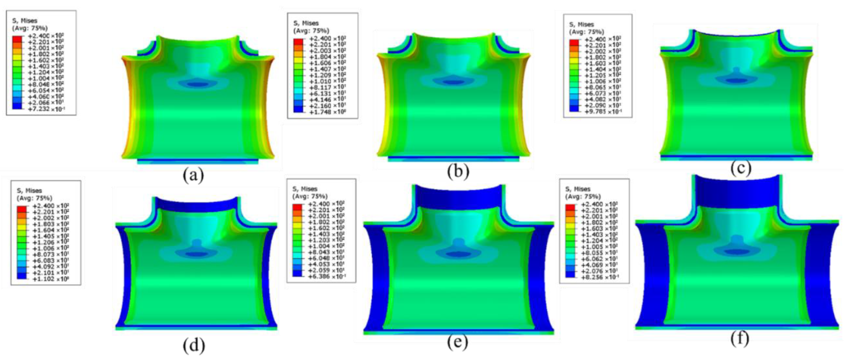
The critical design parameters for the special-shaped sleeve are the minimum thickness, the material properties of the sleeve, the length between the edge of the sleeve and the girth weld, the gap between the sleeve and the tee, and the locations of the injection and exhaust holes.
(2)
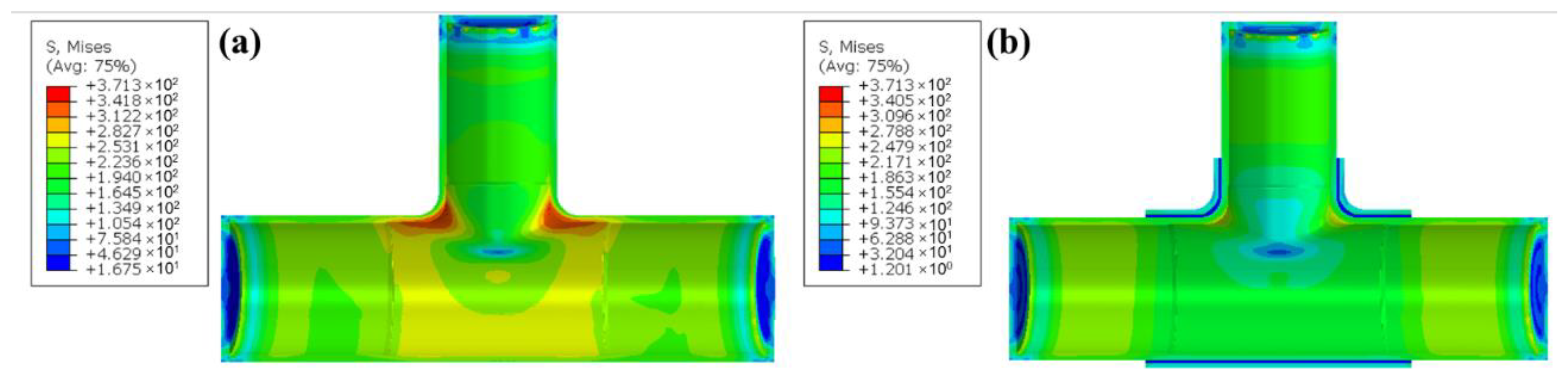
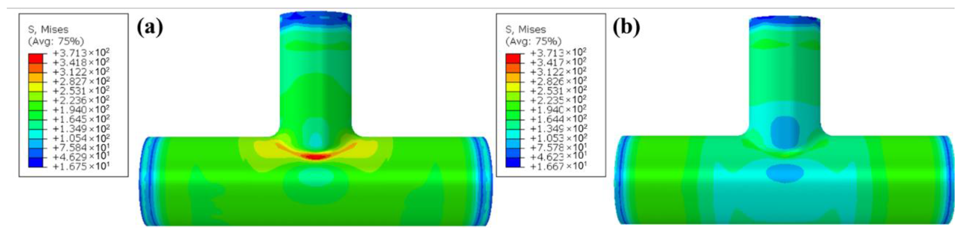
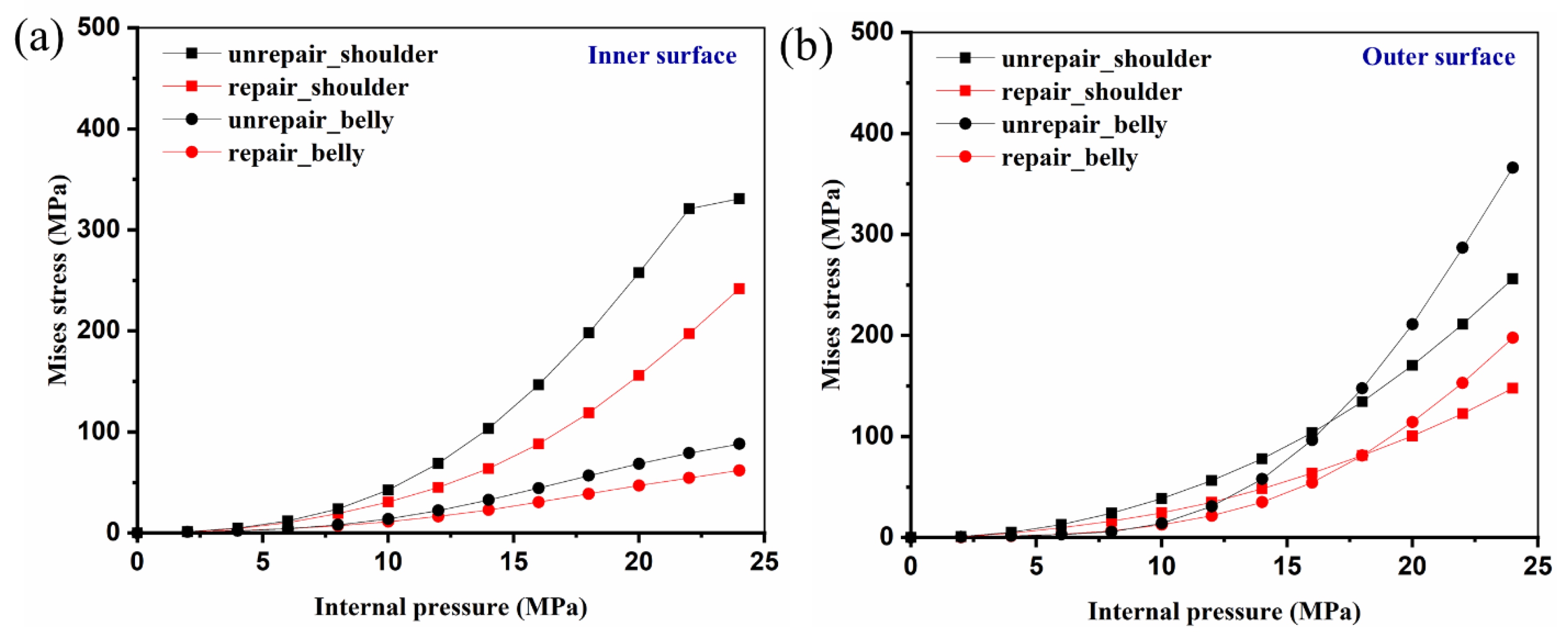
The strain concentrations of the unrepaired tee were greatly reduced, especially for the belly. The maximum strain was ~0.006 on the outer surface of the belly, and it decreased from ~0.006 to ~0.001 under hydrostatic pressure of 24 MPa, where the decreasing rate was about 80%.
(3)
The yielding and burst pressure was improved from ~32 MPa and ~48.6 MPa to ~42 MPa and ~50.8 MPa, respectively, which demonstrates the good reliability of the special-shaped epoxy resin steel sleeve repairing low-strength tee.

Author Contributions

Conceptualization, J.C., W.M. and H.J.; methodology, J.C.; software, J.C. and H.N.; validation, T.Y. and J.R.; formal analysis, H.N., X.L. and W.D.; investigation, J.C.; data curation, J.C. and X.L.; writing—original draft preparation, J.C.; writing—review and editing, K.W. and H.J.; supervision, W.M.; project administration, H.J.; funding acquisition, J.C. All authors have read and agreed to the published version of the manuscript.

Funding

This research was funded by the Young Scientists Fund of the National Natural Science Foundation of China [grant number 51904332], the Natural Science Foundation of Shaanxi Province, China [grant number 2020JQ-934], and the Scientific research and technology development projects of CNPC [grant number 2019D-5009-13].

Data Availability Statement

Not applicable.

Conflicts of Interest

The authors declare no conflict of interest.

References

  1. Cao, J.; Ma, W.; Pang, G.; Wang, K.; Yao, T. Failure analysis on girth weld cracking of underground tee pipe. Int. J. Press. Vessel. Pip. 2021, 191, 104371. [Google Scholar] [CrossRef]
  2. Su, W.; Luo, W.; Dong, X.; Liu, R. Ultimate Strength Analysis of Local Thinning Tee Pipe Considering Plastic Strengthening Effect. J. Phys. Conf. Ser. 2020, 1650, 022024. [Google Scholar] [CrossRef]
  3. Shuai, Y.; Wang, X.; Wang, J.; Yin, H.G.; Cheng, Y.F. Modeling of mechanical behavior of corroded X80 steel pipeline reinforced with type-B repair sleeve. Thin Walled Struct. 2021, 163, 107708. [Google Scholar] [CrossRef]
  4. Jaske, C.E.; Hart, B.O.; Bruce, W.A. Pipeline Repair Manual; Pipeline Research Council International: Arlington, VA, USA, 2006; pp. 1–196. [Google Scholar]
  5. American Society of Mechanical Engineers. Repair of Pressure Equipment and Piping; American Society of Mechanical Engineers: New York, NY, USA, 2015. [Google Scholar]
  6. Lim, K.S.; Azraai, S.; Yahaya, N.; Noor, N.M.; Kim, J. Behaviour of steel pipelines with composite repairs analysed using experimental and numerical approaches. Thin Walled Struct. 2019, 139, 321–333. [Google Scholar] [CrossRef]
  7. Rinastiti, M. The Effect of Aging on Composite-to-Composite Repair Strength; Citeseer: State College, PA, USA, 2010. [Google Scholar]
  8. Savari, A.; Rashed, G.; Eskandari, H. Time-Dependent Reliability Analysis of Composite Repaired Pipes Subjected to Multiple Failure Modes. J. Fail. Anal. Prev. 2021, 21, 2234–2246. [Google Scholar] [CrossRef]
  9. Karpenko, M.; Prentkovskis, O.; Šukevičius, Š. Research on high-pressure hose with repairing fitting and influence on energy parameter of the hydraulic drive. Eksploat. Niezawodn. Maint. Reliab. 2021, 24, 25–32. [Google Scholar] [CrossRef]
  10. Batisse, R. Review of gas transmission pipeline repair methods. In Safety, Reliability and Risks Associated with Water, Oil and Gas Pipelines; Springer: Berlin/Heidelberg, Germany, 2008; pp. 335–349. [Google Scholar]
  11. Stephens, D.; Leis, B.; Francini, R. Developments in criteria for repair or replacement decisions for pipeline corrosion defects. In Proceedings of the 3 Congreso y Expo Internacional de Ductos, Monterrey, Mexico, 13–15 December 1998; pp. 268–275. [Google Scholar]
  12. Wood, A. Evolution of epoxy sleeve pipeline repair technology. Pipes Pipelines Int. 2015, 23, 50–52. [Google Scholar]
  13. CSA-Z662-2007; Oil and Gas Pipeline Systems. Canadian Standards Association: Toronto, ON, Canada, 2007.
  14. Novák, P.; Žmindák, M.; Pelagić, Z. High-pressure pipelines repaired by steel sleeve and epoxy composition. In Applied Mechanics and Materials; Trans Tech Publications Ltd.: Bäch, Switzerland, 2014; pp. 181–188. [Google Scholar]
  15. Mazurkiewicz, L.; Tomaszewski, M.; Malachowski, J.; Sybilski, K.; Chebakov, M.; Witek, M.; Yukhymets, P.; Dmitrienko, R. Experimental and numerical study of steel pipe with part-wall defect reinforced with fibre glass sleeve. Int. J. Press. Vessel. Pip. 2017, 149, 108–119. [Google Scholar] [CrossRef]
  16. Arif, A.; Al-Nassar, Y.N.; Al-Qahtani, H.; Khan, S.; Anis, M.; Eleiche, A.; Inam, M.; Al-Nasri, N.I.; Al-Muslim, H.M. Optimization of pipe repair sleeve design. J. Press. Vessel. Technol. 2012, 134, 51702. [Google Scholar] [CrossRef]
  17. Jaszak, P.; Skrzypacz, J.; Borawski, A.; Grzejda, R. Methodology of Leakage Prediction in Gasketed Flange Joints at Pipeline Deformations. Materials 2022, 15, 4354. [Google Scholar] [CrossRef] [PubMed]
  18. Shang-Peng, L.; Lei, Y.; Xuan-Peng, Q.; Xuefei, D.; Weihua, X.; Huatian, X.; Zhenhua, C. The Applicability Study of Special Steel Sleeve Filled with Epoxy Resin for the Leakage of Welding Connection Platform on Brine Pipeline. Total Corros. Control 2016, 8, 57–59. [Google Scholar]
  19. Ahmad, K.; Baig, Y.; Rahman, H.; Hasham, H. Progressive failure analysis of helicopter rotor blade under aeroelastic loading. Aviation 2020, 24, 33–41. [Google Scholar] [CrossRef]
  20. Fowler, J.R.; Alexander, C.R. Design Guidelines for High-Strength Pipe Fittings; American Gas Association, Inc.: Arlington, VA, USA; Stress Engineering Services: Houston, TX, USA, 1994. [Google Scholar]
Figure 1. Critical design parameters of the special-shaped steel sleeve.
Metals 12 02149 g001
Figure 2. Six numerical-simulation verified SSESS repair modes with different L h : (a) −175 mm, (b) −100 mm, (c) 0 mm, (d) 100 mm, (e) 200 mm, (f) 300 mm.
Metals 12 02149 g002
Figure 3. Yielding pressure and MAWP with the change of L h .
Metals 12 02149 g003
Figure 4. Design of exhaust and injection holes for special-shaped steel sleeves.
Metals 12 02149 g004
Figure 5. Design drawing of the special-shaped steel sleeve.
Metals 12 02149 g005
Figure 6. Surface cleaning and sand-blasting: (a) low-strength tee, and (b) special-shaped sleeve.
Metals 12 02149 g006
Figure 7. Bonding process of the strain gauge. The locations of these strain gauges were designed to study the critical regions: the girth weld region (#1, #2, #3, #4, #7, #8), shoulder (#3 and #5), belly (#12), the bottom of the main pipe (#9), and the reference area (#10 and #11).
Metals 12 02149 g007
Figure 8. Installation process of special-shaped steel sleeves: (a) positioning, (b) gap adjustment, and (c) bolt fastening.
Metals 12 02149 g008
Figure 9. Injecting process of SSESS: (a) end sealing, (b) injection resin, and (c) filling signal.
Metals 12 02149 g009
Figure 10. SSESS after curing for one week.
Metals 12 02149 g010
Figure 11. Hydraulic test structural part: (a) unrepaired tee, and (b) SSESS repaired tee.
Metals 12 02149 g011
Figure 12. Mesh design of the tee and straight parts.
Metals 12 02149 g012
Figure 13. Simulation Mises stress contours with different L h at P = 12 MPa: (a) −175 mm; (b) −100 mm; (c) 0 mm; (d) 100 mm; (e) 200 mm; (f) 300 mm.
Metals 12 02149 g013
Figure 14. Comparisons of strain at monitoring locations between FEM and the experiment: (a) unrepaired and (b) repaired tees.
Metals 12 02149 g014
Figure 15. Stress contour of the inner surface of low strength under a hydrostatic pressure of 24 MPa: (a) unrepair, and (b) SSESS repair.
Metals 12 02149 g015
Figure 16. Stress contour of the outer surface of low strength under a hydrostatic pressure of 24 MPa: (a) unrepair, and (b) SSESS repair.
Metals 12 02149 g016
Figure 17. Mises stress tendencies of critical regions (shoulder and belly of tee) between unrepaired and repaired tees with the increase in internal pressure: (a) inner surface and (b) outer surface.
Metals 12 02149 g017
Figure 18. Experimental hydraulic burst curves of unrepaired and SSESS repaired.
Metals 12 02149 g018
Figure 19. Failure of SSESS with bolt fracture.
Metals 12 02149 g019
Figure 20. Simulated prediction and experimental verification of the blasting location for the unrepaired low-strength tee.
Metals 12 02149 g020
Figure 21. Simulated prediction and experimental verification of the blasting location for the SSESS repaired low-strength tee.
Metals 12 02149 g021
Figure 22. Comparisons of strain monitoring between unrepaired and SSESS repaired tees: (a) 18 MPa, and (b) 24 MPa.
Metals 12 02149 g022
Table 1. The properties of the tee of the same batch and furnace.
Yield Strength
(MPa)
Ultimate Tensile Strength
(MPa)
Elongation
(%)
S1 (branch pipe)34353929.5
S2 (shoulder)37450229.5
S3 (main pipe)36355327.5
Table 2. Properties of epoxy resin.
PropertiesUnitRequirements
Hardness of the resin after curingShore D80 ± 10
Mass solid content%≥99.5
Curing shrinkage%≤0.4
Compressive strength of the resin after curingMPa≥50
(50% deformation)MPa≥10
Shear strengthMPa≥10
Table 3. Properties of S1, S2, and S3 parts.
Region of TeeE (GPa)K (MPa)n
S1207281.00.295
S2211183.50.295
S3209271.00.275
Publisher’s Note: MDPI stays neutral with regard to jurisdictional claims in published maps and institutional affiliations.

