Article

Effect of Notch Structure and Notch Bottom Diameter on the Tensile Load of a Certain GH4169 Notch Bolt for a Device for Longitudinal Separation of Fairing

1
School of Mechanical Engineering, Dalian Jiaotong University, Dalian 116028, China
2
Research and Development Department, Oriental Bluesky Titanium Technology Co., Ltd., Yantai 264000, China
3
School of Mechanical Engineering, Shenyang Ligong University, Shenyang 110158, China
*
Authors to whom correspondence should be addressed.
Metals 2022, 12(12), 2127; https://doi.org/10.3390/met12122127
Submission received: 30 October 2022 / Revised: 29 November 2022 / Accepted: 8 December 2022 / Published: 11 December 2022

Abstract

:
The effect of the notch structure and bottom diameter of a GH4169 notch bolt for an explosive separation device used for longitudinal separation of the fairing, and GH4169 strength range on the tensile load was studied by combing simulations with tests. The results show that the V-shaped, arc-shaped and square notch structures can improve the tensile load of the bolt but to a lesser degree in sequence, and the arc-shaped notch structure performs best in terms of tensile load, fracture appearance and shear resistance. In order to meet the design requirements of 14–15.5 KN tensile load for the notch bolt with an arc-shaped structure, four raw material tensile intervals corresponding to the notch bottom diameters were established by using domestic GH4169 grade C cold-drawn bars.

1. Introduction

The explosive separation device for longitudinal separation of the fairing consists of multiple unlocking joints and docking units [1]. The controlled fracture of the notch bolt as a core connector is directly related to the connection and separation of the two halves of the fairing of the carrier rocket. Conventional notch bolts are made of 30CrMnSiNi2A, which often suffers from hydrogen embrittlement [2], zinc embrittlement and cadmium embrittlement, causing many failures of various types and its use is being gradually restricted in the aerospace industry and other fields. GH4169 (labeled as Inconel718 in other countries) is a nickel-based high-temperature alloy with high-strength, excellent high- and low-temperature performance, high corrosion resistance, excellent high-temperature creep resistance, no risk of hydrogen embrittlement, etc. It is widely used in aerospace engines, carrier rockets, weapons, aircraft and other models, and the bars made of it are widely used to manufacture high-end fasteners for military devices both in China and abroad [3,4,5,6]. Using GH4169 rather than 30CrMnSiNi2A to manufacture the notch bolts for a longitudinal separation of the fairing device has become an important technical research task.
H. Yang [7] used LS-PREPOST software to analyze the fracture direction and stress–strain at the V-shaped notch of the exploding bolt, the load characteristics of the exploding unit and the overall response of the bolt body, obtained the equivalent stress and equivalent plastic strain at the notch, designed the notch structures with different angles and depths and obtained the explosion impact characteristics of the bolt body in various cases. The optimum fracture structure of the exploding bolt body is obtained by comparing it with the explosion impact and explosion impulse of the original bolt. F. Zhang et al. [8] developed a design process for low-impact separation bolts and validated it experimentally. W.Y. Lin [9] used ABAQUS finite element software to establish a simulation model to systematically study the tension and shear of the high-strength bolt at high temperatures. L.F. Du et al. [10] studied the process of explosive bolt action and separation dynamics by combining simulations with tests to explore the research methods and gain experience for the development of explosive bolt technology. C.C. Yang et al. [11] analyzed and optimized the installation process for the explosive bolts for a carrier rocket model, thus effectively improving the installation reliability and efficiency and reducing the lock-up risk. X.C. Song [12] studied the effect of surface treatment of notch bolts on their preload and achieved better results, which is of great value for engineering applications.
This paper studied the effect of the notch structure and notch bottom diameter on the tensile load of the domestic high-quality GH4169 notch bolt by means of ABAQUS finite element simulation and experimental comparison, determined the optimal notch structure and the notch bottom diameters of the bolt in different tensile strength ranges, which meet the design requirements, quantified the notch strengthening effects and provided a theoretical and experimental basis for the development and use of notch bolts.

2. Establishment of the Simulation Model

2.1. Establishment of the Finite Element Model (FEM)

We established the bolt models with a non-notch structure and a notch structure, respectively, using finite element software (Figure 1), to analyze the effect of the notch structure and notch bottom diameter on the tensile strength of the bolt.

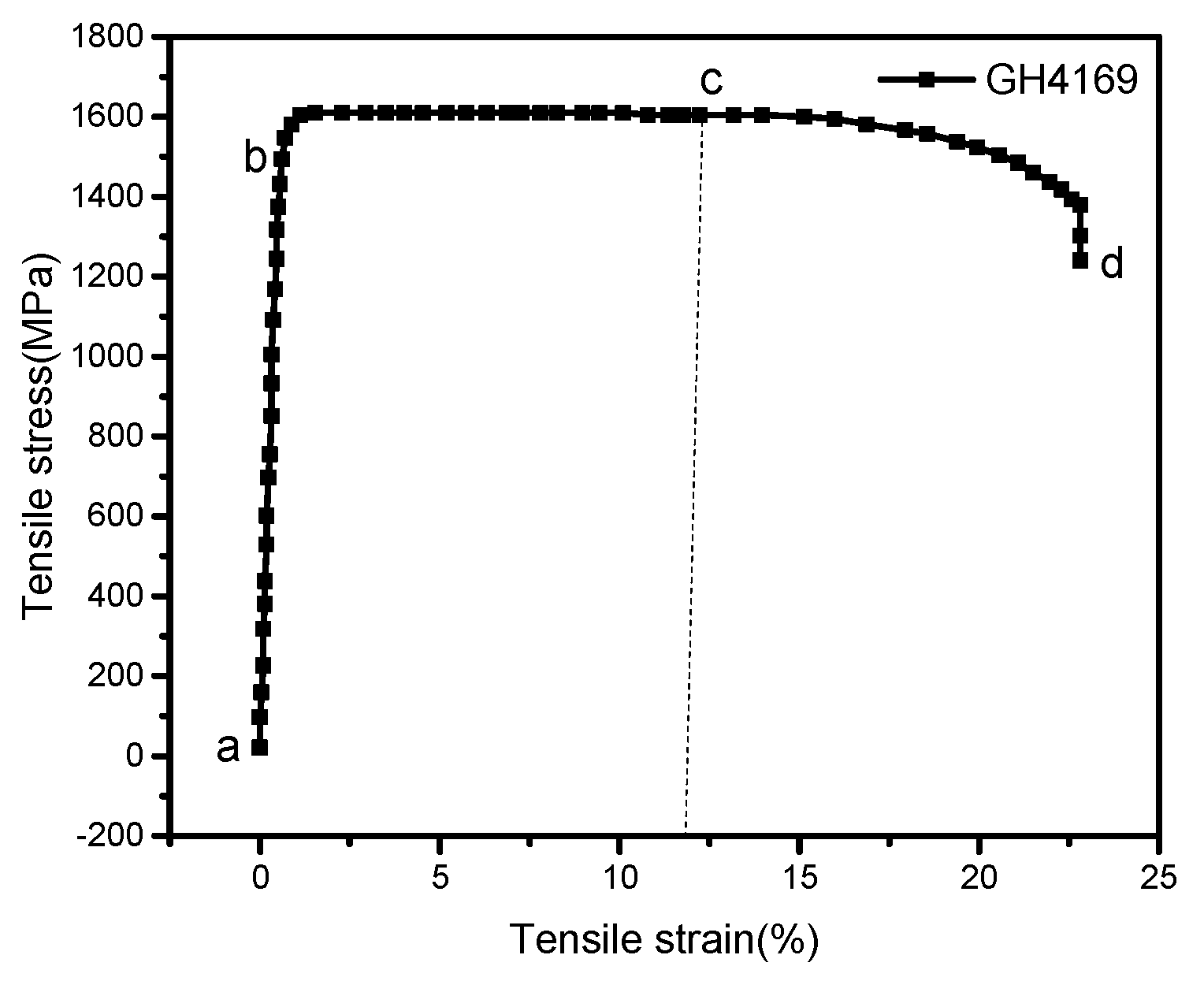
2.2. Material Properties
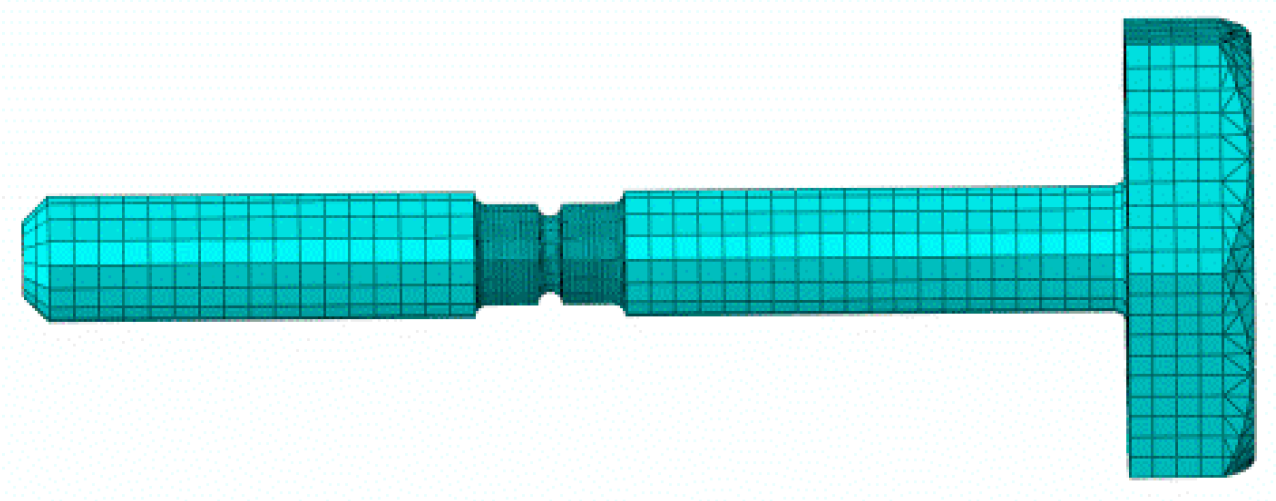
We defined the material properties of GH4169 for the notch bolts, including the material density, Young’s modulus, Poisson’s ratio, yield strength and tensile strength, which are listed in Table 1. The tensile stress–strain curve in Figure 2 is derived from the tensile test of the raw material GH4169 tensile specimen. The yield strength and the tensile strength are derived from the GH4169 stress–strain curve.
In Figure 2, a–b is the initial elastic stage, b–c is the plastic yield and strain hardening stage, and c–d, the bearing capacity decreases after point c until the material is damaged. At point c, the damage criterion is activated, beyond which the stress–strain response is changed to the localized stiffness degradation evolution criterion. Therefore, the plastic parameters in ABAQUS need to be input in stages according to the stress–strain curve.
The ductile damage model is commonly used in the tensile failure process of metal materials. The material parameters of the damage model can be obtained through the tensile stress–strain curve, and the damage parameters are shown in Table 2. The fracture strain parameter shown in Figure 2c points to corresponding strain; triaxial stress degree is the most commonly used kind of ductile metal stress state parameter, as it can well reflect the stress state of various kinds of materials under complex stress state and tensile state; triaxial stress degree η value is always positive, compression, triaxial stress degree η is always negative. Pure shear, η = 0; when the uniaxial tension, η = 1/3; in uniaxial compression, η = −1/3. The working condition of the concave bolt is slow tensile, that is, quasi-static tensile, so the strain rate is defined as 0.

2.3. Gridding

The notch bolt was meshed into hexahedral cells with a side length of 1 mm, and the notched area had a denser mesh size of 0.1 mm, as shown in Figure 3. Hexahedral cells are preferred because they take less time and are more accurate than other cells. The 8-node hexahedral linear reduction integral element was established, which is less prone to shear self-locking under bending load, and the results of the displacement solution are more accurate; moreover, the accuracy of analysis will not be significantly affected when the mesh is deformed.

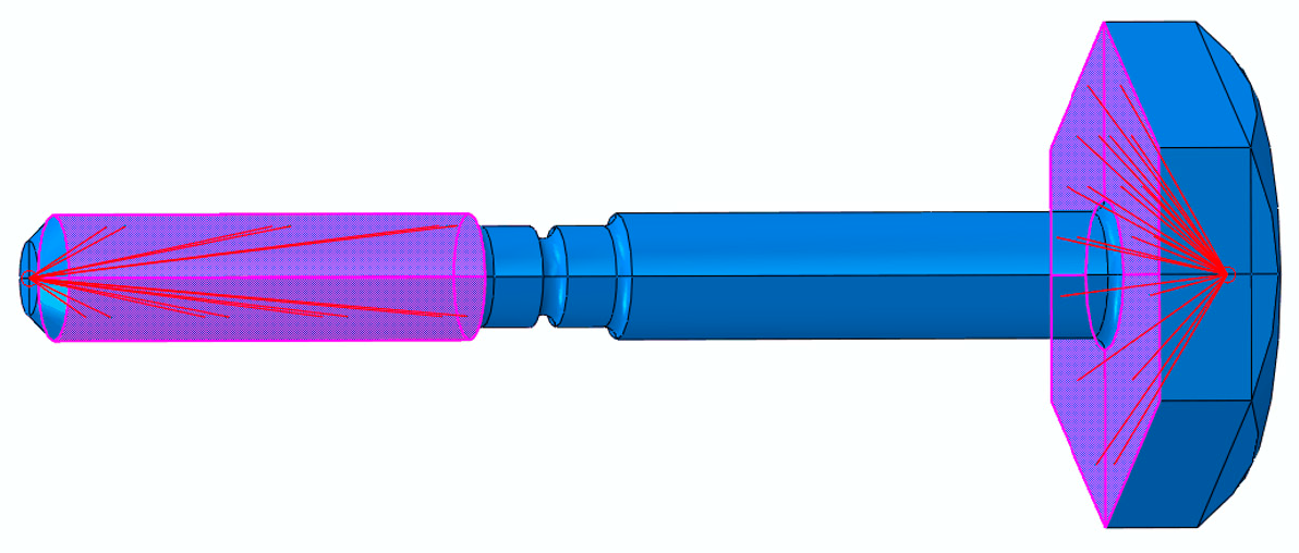
2.4. Boundary Conditions and Loads

The Abaqus/Standard analysis module was used to conduct bolt quasi-static tensile simulation analysis. The time period was set to 0.3 s and evenly spaced time intervals were set to 100. So, the stretching simulation is performed in 100 steps. As in Figure 4, the bottom surface of the bolt head is coupled to the right reference point to fix the reference point completely; the left cylindrical surface of the bolt is coupled to the left reference point and a displacement to the left is applied to the reference point; as the displacement increases, the tension will increase until the bolt breaks completely.

2.5. Yield Criterion and Hardening Criterion

The bolt is deformed under load, moving from the elastic phase to the plastic phase, and then to the hardening phase. The stress is proportional to the strain in the elastic phase. When the stress gradually increases to the yield limit of the material, the plastic deformation of the material lattice occurs, and the load increases till the material reaches the hardening phase [13,14,15]. The yield criterion and the hardening criterion are important indicators of plastic deformation in finite element calculations [16,17,18,19].

2.5.1. Yield Criterion

The equivalent stress is usually calculated using the von Mises yield criterion, which is shown in Equations (1)–(3).
F 0 ( σ i j ) = 1 2 S i j S i j 1 3 σ s 2 = 0
where σs is the yield stress;
s i j = σ i j σ m δ i j is the deviator stress tensor; σij is the stress tensor; σmδij is the spherical stress tensor;
σ s = 1 2 [ ( σ 1 σ 2 ) + ( σ 2 σ 3 ) + ( σ 1 σ 3 ) 2 ]
σ s = 1 2 [ ( σ x σ y ) 2 + ( σ y σ z ) 2 + ( σ x σ z ) 2 + 6 ( τ x y 2 + τ y z 2 + τ x z 2 ) ]
where σ1, σ2 and σ3 are the principal stresses; σx, σy, σz, τxy, τyz and τxz are the stress components.
In the two-dimensional stress plane, the von Mises yield condition corresponds to an ellipse, while in the three-dimensional stress space, the yield plane is a cylindrical plane. When the stress value is inside the yield surface, the material is in the elastic phase; when the stress value is outside the yield surface, the material would yield.

2.5.2. Hardening Criterion

The hardening criterion describes the development of the initial yield of a material under its plastic strain. The size, center and shape of the yield surface of a material under complex stress conditions would also change, and therefore need to be redefined. In the von Mises yielding criterion, the yield surface is evenly expanded. If the initial yield condition is defined as f ( σ i j ) = 0 , then the hardening model is as shown in Equation (4).
ϕ ( σ i j , H α ) = f ( σ i j ) k ( H α ) = 0
where k ( H α ) = k is the hardening function, H α is a parameter reflecting the material deformation history, including hardening parameters, which can be scalar or tensor, and the value of k increases gradually during plastic loading.

3. Simulation of the Effect of the Notch Structure on the Tensile and Shear Loads

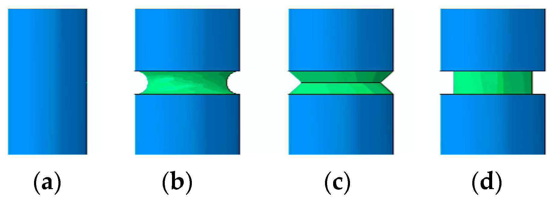
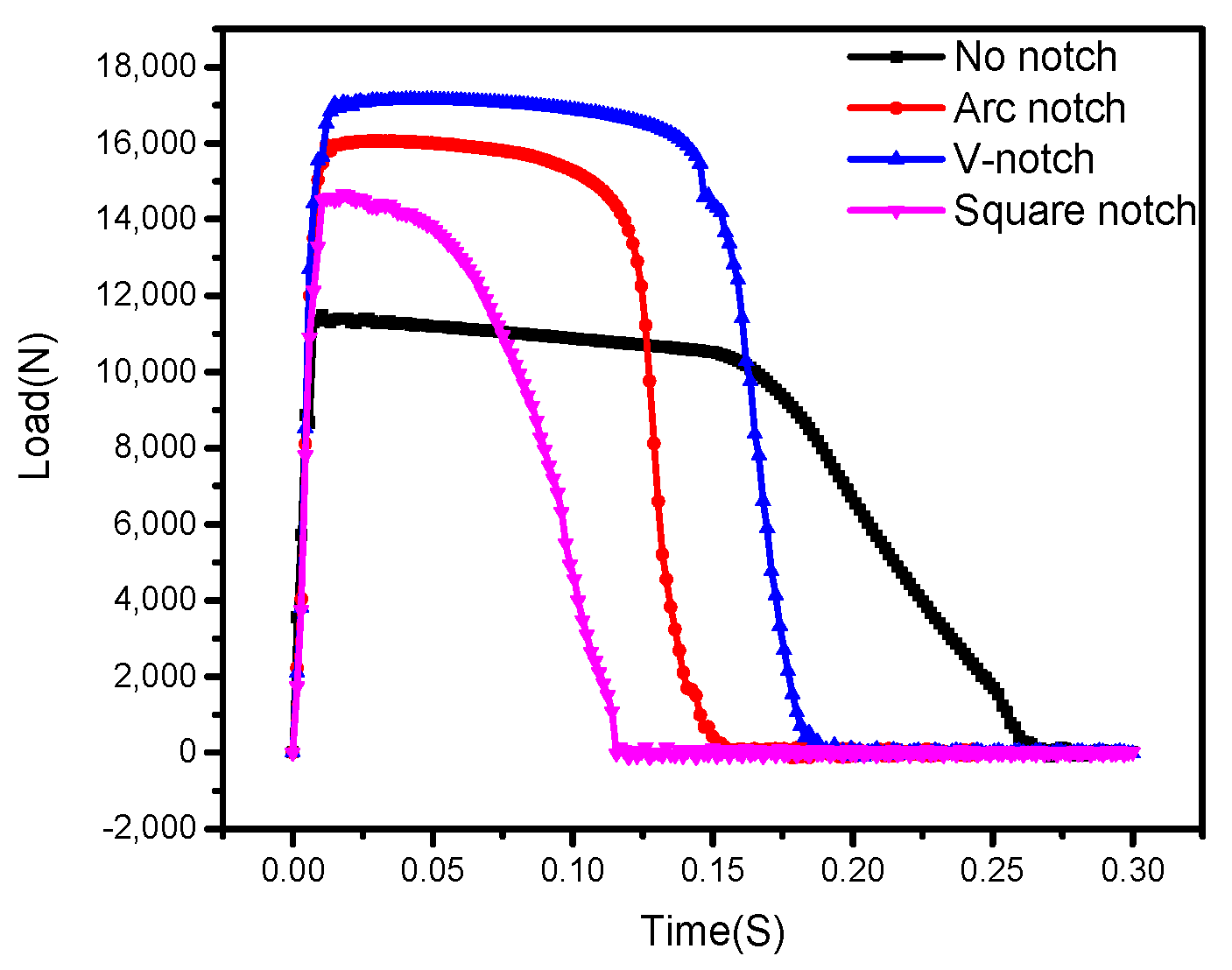
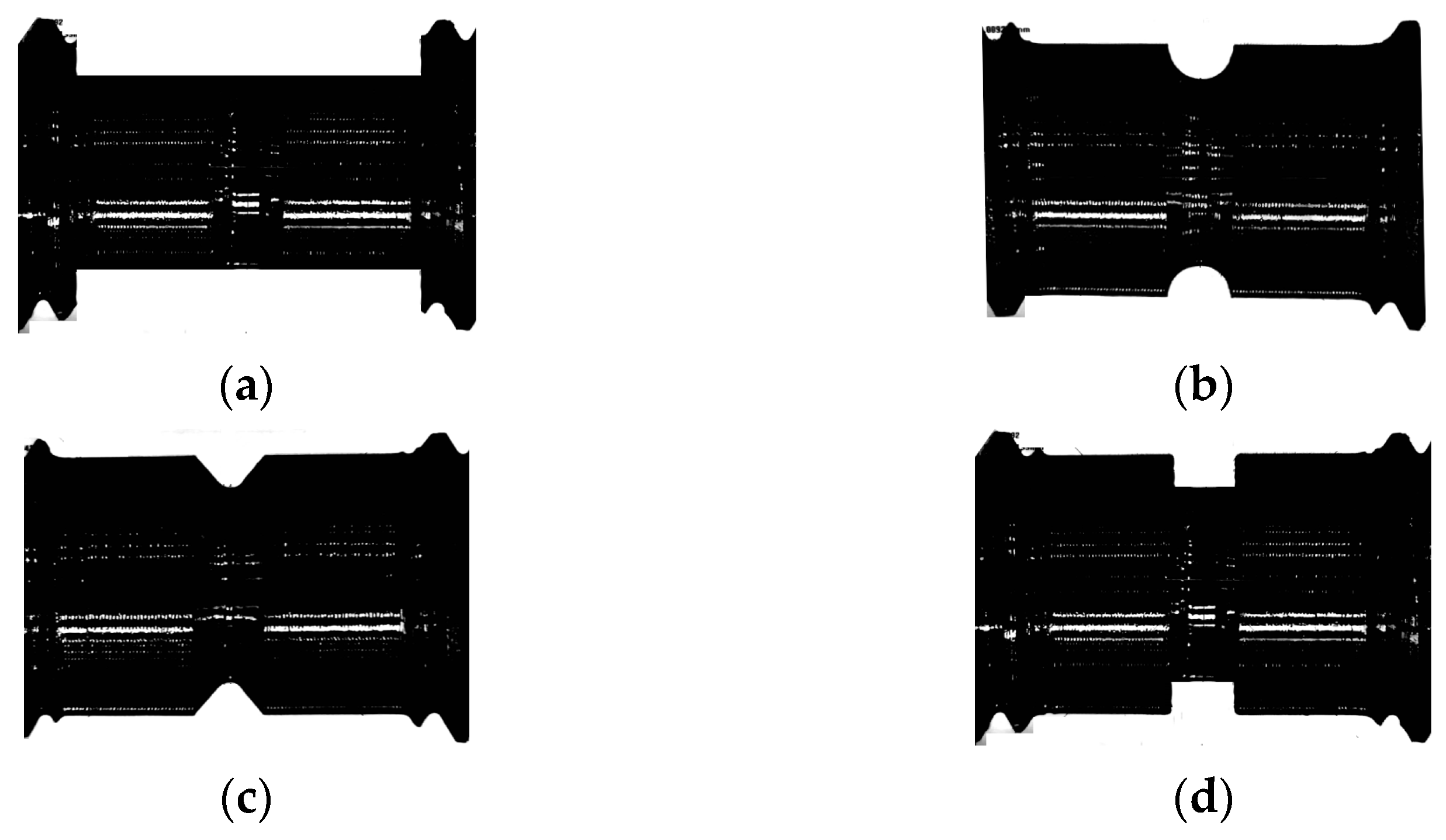
3.1. Tensile Loads of Different Notch Structures

Four types of bolts with a non-notch structure, an arc-shaped notch structure, a V-shaped notch structure and a square notch structure are modeled. The effect of notch structure on the tensile strength of the bolt is analyzed. As shown in Figure 5a, the outer diameter is 3.0 mm; in Figure 5b–d the notch bottom diameter is 3.0 mm and the notch upper/lower outer diameter is 4.0 mm.
The tensile simulation analysis of the four types of bolts and their tensile load/time curves are shown in Figure 6. In addition, the tensile strength of these four mechanisms can be obtained according to the formula σ = Fb/So. The tensile loads and tensile strength of the four structures are listed in Table 3. The tensile strength of the bolt without a notch structure is 1623 MPa, which is basically consistent with the tensile strength of the raw material tensile test specimen of 1609 MPa, which proves the accuracy of the simulation analysis. It can be found that the tensile loads and tensile strength of these four types of structures decrease in the following order: V-shaped structure, arc-shaped, square and non-notch. The tensile load and tensile strength of a bolt with a notch structure are significantly higher than those of a bolt with a non-notch structure. We can confirm that the concave structure plays a role in strengthening the tensile strength of bolts, so we only study the concave structure in the subsequent research process.

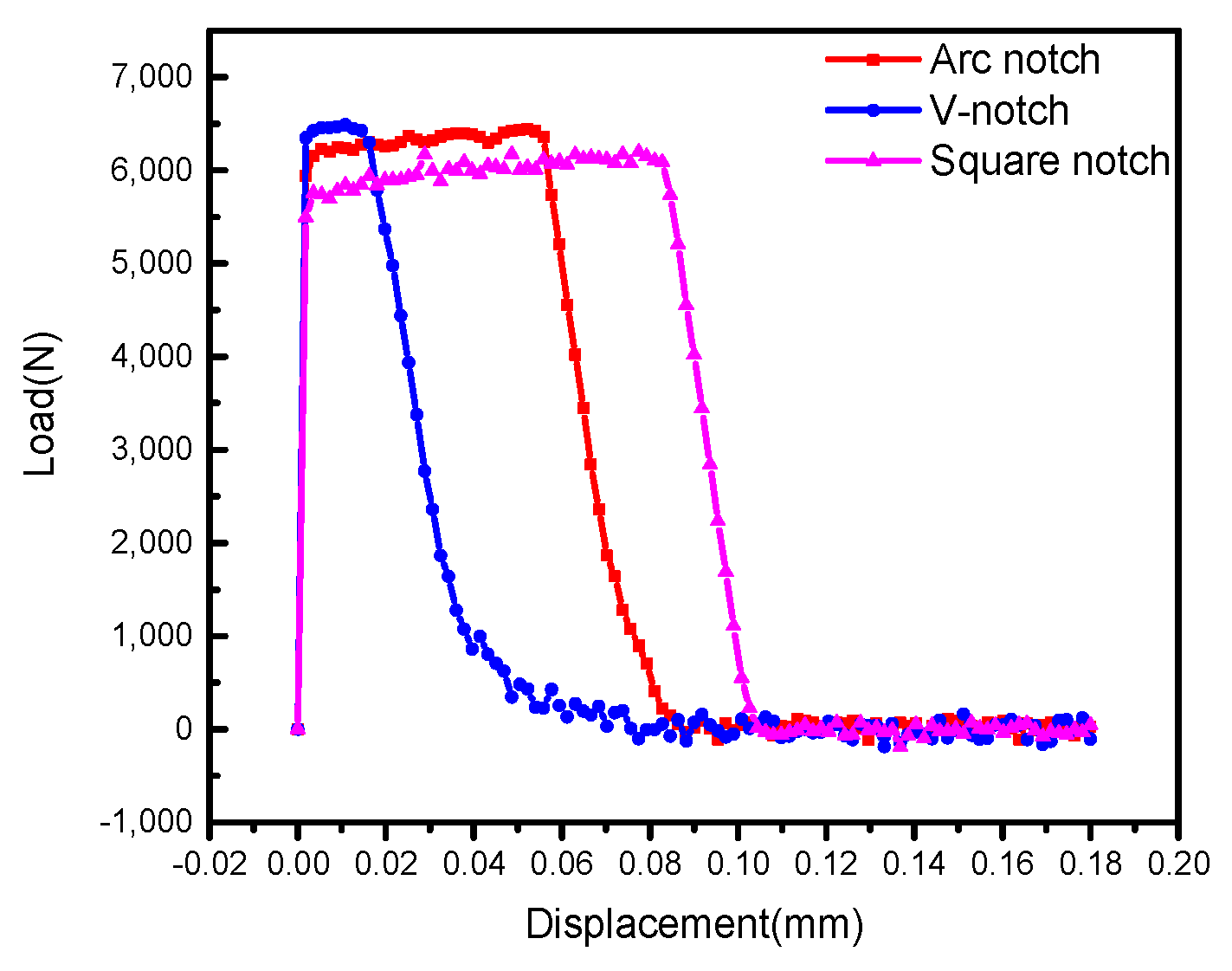
3.2. Shear Loads of Different Notch Structures

The shear simulation analysis of the bolts with an arc-shaped notch structure, a V-shaped notch structure and a square notch structure, and their shear load/time curves are shown in Figure 7. The shear load of the arc-shaped notch structure is 6459 N and its shear displacement is 0.054 mm; the shear load of the V-shaped notch structure is 6487 N and its shear displacement is 0.016 mm; the shear load of the square notch structure is 6166 N and its shear displacement is 0.083 mm. The difference in shear load between the arc-shaped notch structure and the V-shaped notch structure is not significant, but the shear displacement of the arc-shaped notch structure is 3.375 times that of the V-shaped notch structure. The larger the shear displacement, the less likely the bolt is to shear fracture. Therefore, a bolt with an arc-shaped notch structure is more shear resistant than others.

3.3. Effect of the Stamping Velocity on Forming

Figure 8 shows that the simulated fracture appearances of the three notch structures are basically consistent with the fracture appearances obtained from the tensile test shown in Figure 9. The fracture surface (Figure 8 and Figure 9a) of the arc-shaped notch is relatively flat; that of the V-shaped notch (Figure 8 and Figure 9b) is the flattest, while that of the square notch (Figure 8 and Figure 9c) is uneven. This is because the arc-shaped notch and V-shaped notch structures have the smallest cross-section where the fracture occurs, while the square notch structure has the same cross-section size at the notch, and therefore the fracture occurs in a more random way. An arc-shaped notch bolt or a V-shaped notch bolt can precisely control its fracture location, while a square notch bolt cannot control its fracture surface.
In summary, it is concluded that the arc-shaped notch structure can not only greatly improve the tensile and shear loads of the bolt but also accurately control its fracture location. Therefore, the arc-shaped structure is the optimal notch structure.

4. Tensile Simulation Analysis of Arc-Shaped Notch Bolts with Different Bottom Diameters

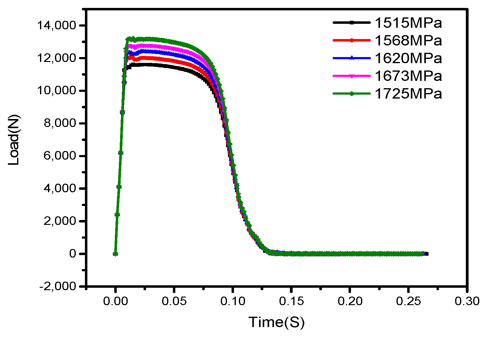
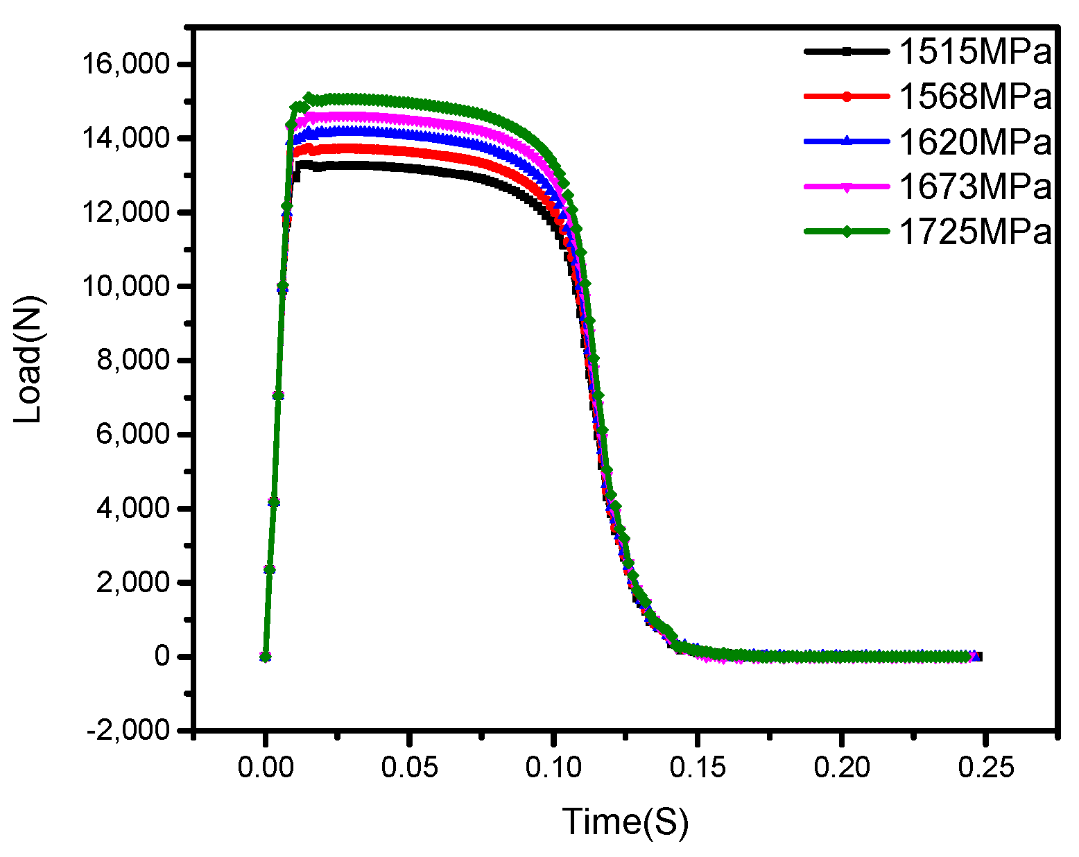
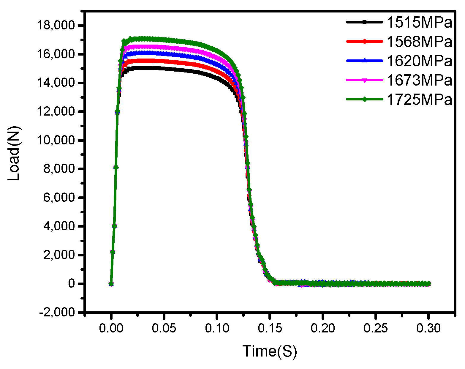
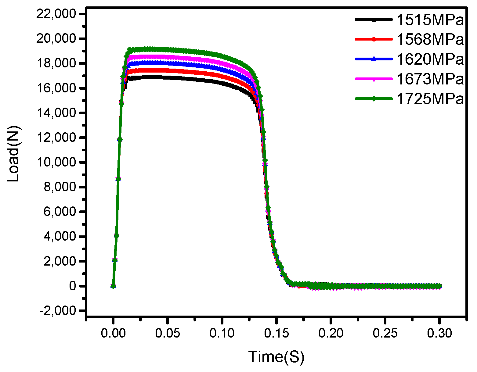
4.1. Tensile Strength Analysis of Notch Bolts with Different Bottom Diameters

According to the design requirements for a certain type of notch bolt, its tensile load should reach 14–15.5 KN. The tensile strength of the raw material for domestic GH4169 grade C cold-drawn bars is 1515–1725 MPa, which is further divided into five grades: 1515, 1568, 1620, 1673 and 1725 MPa. We defined the properties of the materials with the above five tensile strengths for four arc-shaped (R = 0.5 mm, the most commonly used in engineering practices) notch bolt models with notch bottom diameters of 2.6, 2.8, 3.0 and 3.2 mm, respectively, and ran tensile simulations to obtain their tensile loads.
Figure 10, Figure 11, Figure 12 and Figure 13 show the tensile loads of the arc-shaped notch bolts with notch bottom diameters of 2.6, 2.8, 3.0 and 3.2 mm, respectively, under the five tensile strengths. As shown in Table 4, with a notch diameter of 2.6 mm, the tensile load under all five tensile strengths is lower than 14 KN, which does not meet the design requirements. With a notch diameter of 2.8 or 3.0 mm, the ensile load meets the design requirements of 14–15.5 KN under some of the tensile strengths. With a notch diameter of 3.2 mm, the tensile load under all five tensile strengths exceeds 15.5 KN, which does not meet the design requirements.

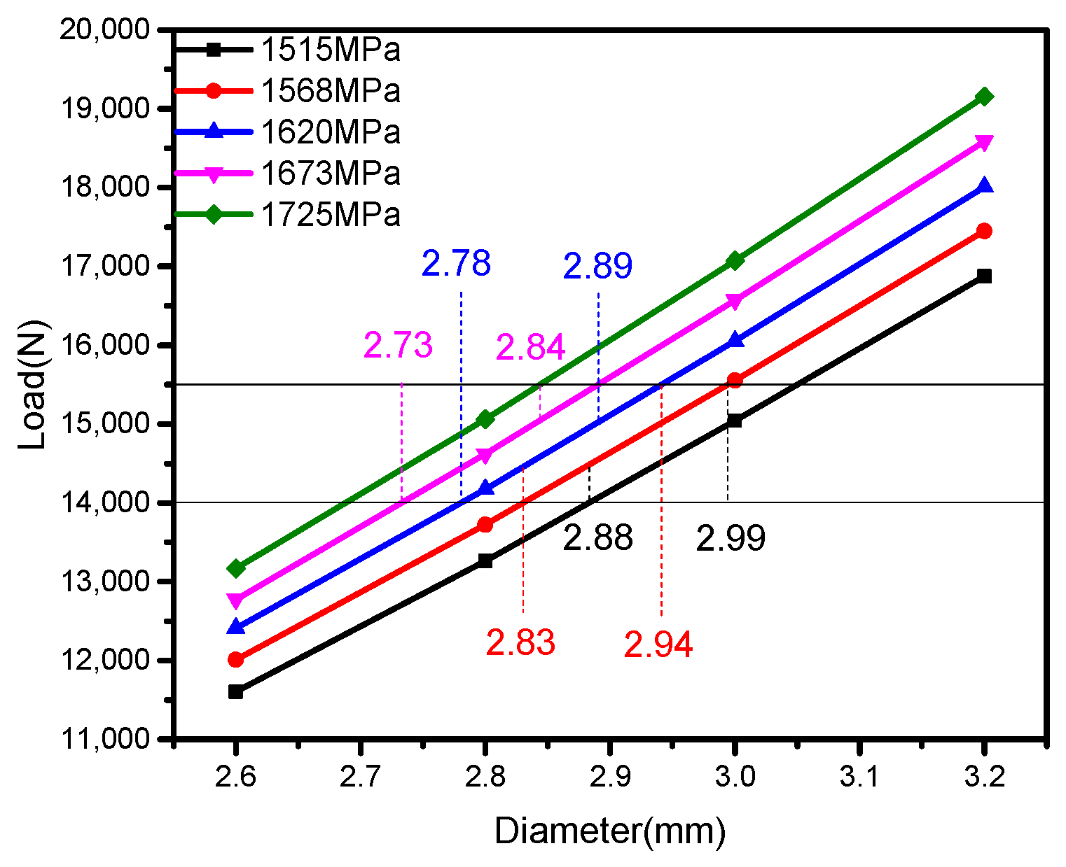
4.2. Determination of the Notch Diameter for Different Tensile Strength Ranges

In order to more intuitively determine the notch bottom diameter that meets the design requirements of 14–15.5 KN, we plotted the bottom diameter–tensile load curves for the five tensile strengths with the notch bottom diameter as the x-axis and the tensile load as the y-axis, as shown in Figure 14.
It can be concluded that with the same material properties, the tensile load is linearly proportional to the bottom diameter. Within the raw material tensile strength range of 1620–1673 MPa, notch bolts with a bottom diameter of 2.78–2.89 mm meet the design requirements; within the raw material tensile strength range of 1673–1725 MPa, notch bolts with a bottom diameter of 2.73–2.84 mm meet the design requirements.

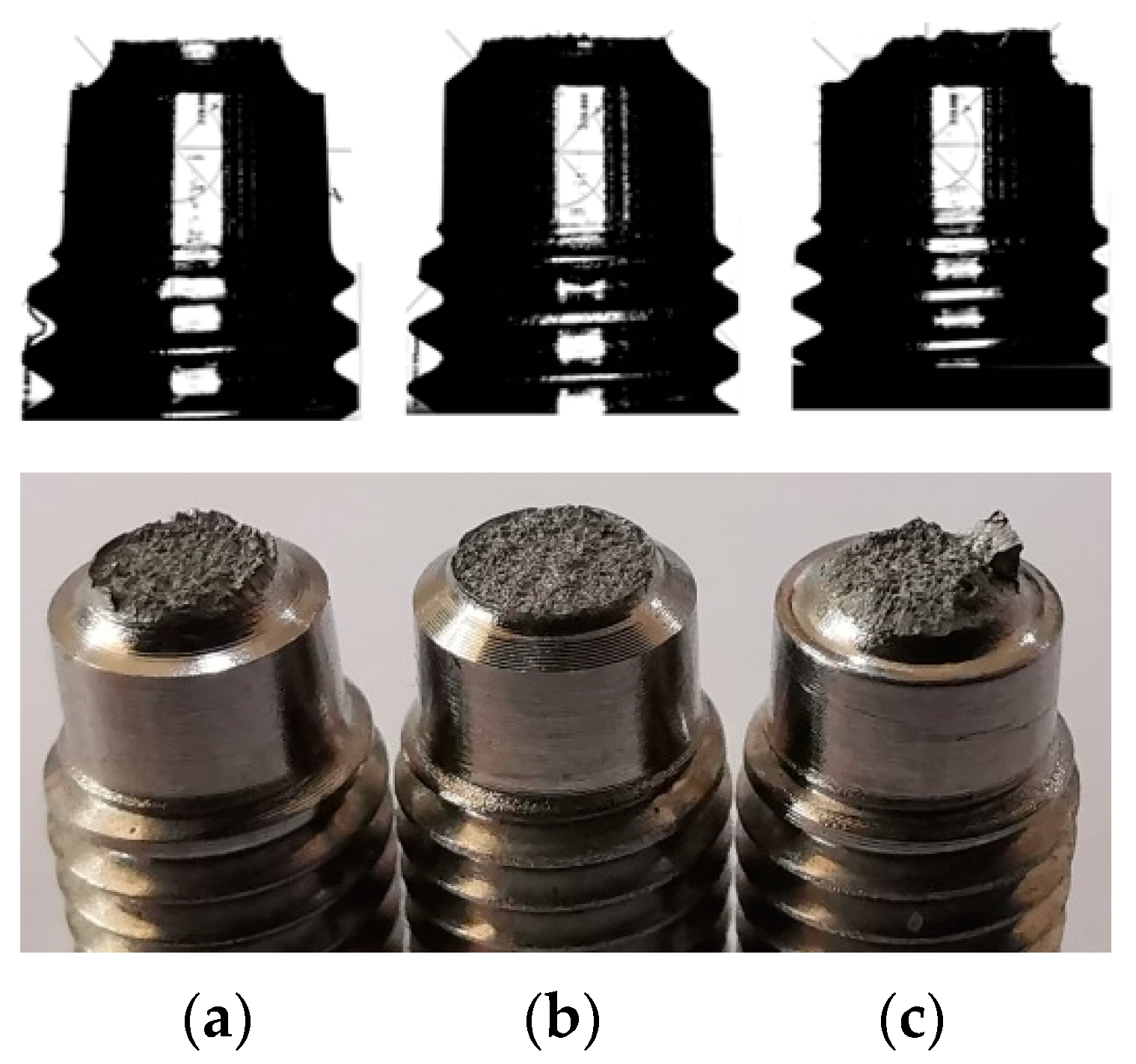
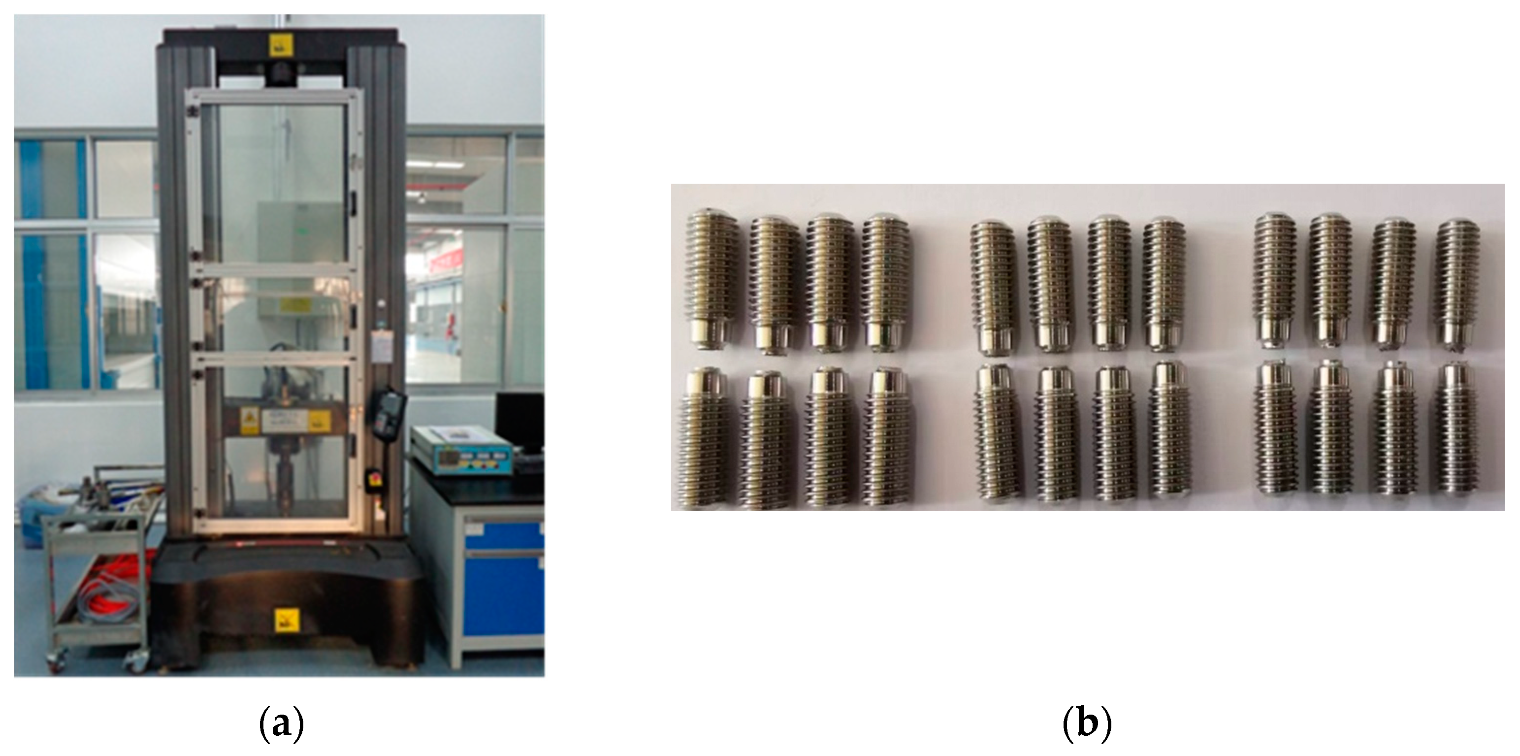
5. Experimental Verification

In order to further verify the effect of the notch structure and bottom diameter on the tensile load of the bolt, high-quality GH4169 grade C cold-drawn bars with a tensile strength of 1609 MPa were used to produce tensile test bars with a non-notch structure (Figure 15a), an arc-shaped notch structure (Figure 15b), a V-shaped notch structure (Figure 15c) and a square notch structure (four bars for each structure) (Figure 15d), respectively. Figure 15 shows the projected images of these notch structures of the test bars. An electronic universal testing machine was used to perform the tensile tests on the test bars (Figure 16a).
The tensile simulation data of the four bolts were compared with their tensile test data, and the results are shown in Table 5. The differences between the simulation results and the test results for the non-notch structure, arc-shaped notch structure, V-shaped notch structure and square notch structure are 4.5%, 1.9%, 6.8% and 4.5%, respectively, which are very small, proving that the simulation results are accurate and reliable and can be used as a theoretical guidance. At the same time, the test results show that the hardening effects of the V-shaped, arc-shaped and square notch structures are 33.7%, 31.2% and 25.6%, respectively.
The raw material with a tensile strength of 1609 MPa was used to produce arc-shaped notch bolts with notch bottom diameters of 2.6, 2.8, 3.0 and 3.2 mm, respectively. A comparison of the simulation results with the test results is shown in Table 6. The differences between the simulation results and the test results are 2.4%, 4.6%, 1.9% and 0.7%, respectively. Once again, the accuracy of the simulation results has been proven.
In summary, by comparing the simulation and test results, we conclude that the simulation models established in the paper are feasible and accurate for studying the notch shapes, bottom diameters, and material strength ranges of notch bolts, as well as the replacement of 30CrMnSiNi2A with the domestic GH4169 Grade C cold-drawn bars.

6. Conclusions

In this paper, by establishing a tensile finite element analysis model of a notch bolt based on the domestic GH4169 Grade C cold-drawn bars and designing verification tests, we conclude that:
(1) The V-shaped, arc-shaped and square notch structures have a hardening effect on the tensile strength of the bolt, which is 33.7%, 31.2% and 25.6%, in decreasing order, respectively.
(2) The arc-shaped notch structure is comparable to the V-shaped notch structure in terms of tensile load and shear load; its shear displacement is 3.375 times that of the V-shaped notch structure; and the arc-shaped notch structure is more shear resistant. The arc-shaped notch structure and V-shaped notch structure have a flat cross-section, allowing precise control of the bolt fracture position. The arc-shaped notch structure performs best in terms of tensile hardening, fracture appearance control and shear resistance.
(3) For a domestic GH4169 C grade cold drawn bar, when the tensile strength and notch bottom diameter fall into the following ranges, the tensile load requirements of 14–15.5 KN for a notch bolt with an arc-shaped (R = 0.5 mm) notch structure can be met. That is, when the tensile strength is 1515–1568 MPa and the notch bottom diameter is 2.88–2.99 mm; when the tensile strength is 1568–1620 MPa and the notch bottom diameter is 2.83–2.94 mm; when the tensile strength is 1620–1673 MPa and the notch bottom diameter is 2.78–2.89 mm; when the tensile strength is 1673–1725 MPa and the notch bottom diameter is 2.73–2.84 mm.

Author Contributions

Conceptualization, X.W. (Xiaoliang Wang) and Y.C.; methodology, X.W. (Xiaoliang Wang); software, T.Y.; validation, X.W. (Xiaoliang Wang) and T.Y.; formal analysis, X.W. (Xiaowei Wang) and Y.C; investigation, Y.C.; resources, X.W. (Xiaoliang Wang) and Y.C; data curation, T.Y. and X.W. (Xiaoliang Wang); writing—original draft preparation, X.W. (Xiaoliang Wang); writing—review and editing, X.W. (Xiaoliang Wang) and Z.J.; visualization, X.W. (Xiaoliang Wang); supervision, Y.C.; project administration, X.W. (Xiaoliang Wang); funding acquisition, Y.C. All authors have read and agreed to the published version of the manuscript.

Funding

This project was supported by the National Natural Science Foundation of China (No. 52175379, 51905071), Doctoral Research Startup Fund Program of Liaoning Province (2019-BS-043).

Data Availability Statement

Some or all data and images generated or used during the present work are available from the corresponding authors upon reasonable request.

Conflicts of Interest

The authors declare no conflict of interest.

References

  1. Ren, D.H. An Explosion Separation Device for Longitudinal Separation of the Fairing. Chinese Patent CN2013101728026A, 11 September 2013. [Google Scholar]
  2. Yang, Z.D.; Gu, H.; Zhang, G.S.; Deng, C. Study on the brittle fracture of 30CrMnSiNi2A bolts. Chin. Equip. Eng. 2018, 10, 73–75. [Google Scholar]
  3. Fang, J.; Wu, M.; Zhang, T.; Tao, Y.; Liu, J.; Jin, K. Hot forging process on superalloy GH4169 bolt. Forg. Press. Technol. 2022, 47, 8–22. [Google Scholar]
  4. Tang, T.; Wang, R. Numerical simulation and parameter optimization on hot upsetting for GH4169 alloy dodecagonal heat bolt. Forg. Press. Technol. 2021, 46, 20–26. [Google Scholar]
  5. Yang, Z.Y. Research on Stress Relaxation Behavior and Finite Element Simulation of GH4169 Alloy; Harbin Institute of Technology: Harbin, China, 2020. [Google Scholar]
  6. Gao, S.Y.; Wang, Y.W.; Su, R. Low-Cycle fatigue behavior of GH4169 superalloy. Rare. Met. 2022, 46, 289–296. [Google Scholar]
  7. Yang, H. Research on Fracture Characteristics of Explosive Bolts Based on Finite Elements; Harbin Institute of Technology: Harbin, China, 2017. [Google Scholar]
  8. Zhang, F.; Yang, S.B.; Yang, A.M.; Wu, R.D. A low-impact separating bolt design. Fireworks 2006, 3, 14–22. [Google Scholar]
  9. Lin, W.Y. Finite Element Analysis of High Strength Bolted Connections with High Temperature Mechanical Properties; Wuhan University of Technology: Wuhan, China, 2006. [Google Scholar]
  10. Du, L.F.; Ma, Y.H.; Chen, H.N.; Yang, S.B.; Xia, D.X. The simulation of action procedure of explosive bolt. Fireworks 2015, 3, 29–32. [Google Scholar]
  11. Yang, C.C.; Ma, L.; Wang, J.D.; Zhao, Y.N.; Yu, Y. Assembly method of carrier rocket interstage separation explosion bolts. Qualit. Reliat. 2018, 2, 13–15. [Google Scholar]
  12. Song, X.C. Experimental study on mechanical properties of notch bolt under lubricating states. J. Hunan. Inst. Technol. (Nat. Sci. Ed.) 2005, 18, 42–45. [Google Scholar]
  13. Antolovich, S.D.; Armstrong, R.W. Plastic strain localization in metals: Origins and consequences. Prog. Mater. Sci. 2014, 59, 1–160. [Google Scholar] [CrossRef]
  14. Wang, S.; Liu, Y.; Peng, H.; Lu, X.; Wang, J.; Su, X. Microstructure and Mechanical Properties of Al–12.6Si Eutectic Alloy Modified with Al–5Ti Master Alloy. Adv. Eng. Mater. 2017, 19, 105–109. [Google Scholar] [CrossRef]
  15. Li, Y.S.; Tao, N.R.; Lu, K. Microstructural evolution and nanostructure formation in copper during dynamic plastic deformation at cryogenic temperatures. Acta Mater. 2008, 56, 230–241. [Google Scholar] [CrossRef]
  16. Zhang, Y.; Zhou, Y.J.; Lin, J.P.; Chen, G.L.; Liaw, P.K. Solid-Solution Phase Formation Rules for Multi-component Alloys. Adv. Eng. Mater. 2008, 10, 534–538. [Google Scholar] [CrossRef]
  17. Liu, M.H.; Li, C.M.; Wang, C.C.; Luo, X.C. The Compression Analysis of LGJ-300/40 Wire Splicing Sleeve. Northeast Powr. Technol. 2014, 35, 26–29. [Google Scholar] [CrossRef] [Green Version]
  18. Dong, X.H.; Cheng, S.; Tu, T.C.; Zeng, C.; Wu, J. Simulation analysis of compression and tensile fracture of large section wire with steel core and aluminum strand. Elec. Meas. Technol. 2021, 44, 62–69. [Google Scholar]
  19. Jácome, L.A.; Weber, S.; Leitner, A.; Arenholz, E.; Bruckner, J.; Hackl, H.; Pyzalla, A.R. Influence of Filler Composition on the Microstructure and Mechanical Properties of Steel—Aluminum Joints Produced by Metal Arc Joining. Adv. Eng. Mater. 2009, 11, 350–358. [Google Scholar] [CrossRef]
Figure 1. Three-dimensional model of bolt.
Metals 12 02127 g001
Figure 2. Stress-strain curve of GH4169 obtained from the test.
Metals 12 02127 g002
Figure 3. Schematic of notch bolt meshing.
Metals 12 02127 g003
Figure 4. Notch bolt’s fixing surface and load surface diagram.
Metals 12 02127 g004
Figure 5. Bolt models of four structures. (a) Non-notch; (b) arc-shaped; (c) V-shaped; (d) square notch.
Metals 12 02127 g005
Figure 6. Tensile loads of four bolt structures.
Metals 12 02127 g006
Figure 7. Effect of different notch structures on the shear load of a bolt.
Metals 12 02127 g007
Figure 8. Simulated fracture appearances. (a) arc-shaped; (b) V-shaped; (c) square notch.
Metals 12 02127 g008
Figure 9. Fracture appearances of test bolts. (a) arc-shaped; (b) V-shaped; (c) square notch.
Metals 12 02127 g009
Figure 10. Tensile loads under different tensile strengths with a notch bottom diameter of 2.6 mm.
Metals 12 02127 g010
Figure 11. Tensile loads under different tensile strengths with a notch bottom diameter of 2.8 mm.
Metals 12 02127 g011
Figure 12. Tensile loads under different tensile strengths with a notch bottom diameter of 3.0 mm.
Metals 12 02127 g012
Figure 13. Tensile loads under different tensile strengths with a notch bottom diameter of 3.2 mm.
Metals 12 02127 g013
Figure 14. Tensile loads of bolts with different tensile strength–notch bottom diameter pairs.
Metals 12 02127 g014
Figure 15. Projected images of the four tensile test bars. (a) Non-notch; (b) arc-shaped; (c) V-shaped; (d) square notch.
Metals 12 02127 g015
Figure 16. Electronic universal testing machine and tensile test bars. (a) Electronic universal testing machine. (b) V-shaped, arc-shape and square tensile test bars.
Metals 12 02127 g016
Table 1. Main material properties of GH4169.
GH4169 Material PropertiesValue
Density/(g·cm−3)8.24
Young’s modulus (MPa)200,000
Poisson’s ratio0.3
Yield strength (MPa) 1516
Tensile strength (MPa)1609
Table 2. Ductile damage parameter.
Ductile DamageValue
Fracture strain0.12
Stress triaxiality0.33
Strain rate0
Table 3. Comparison of tensile load and tensile strength of four structures.
Type of StructureTensile Load (N)Tensile Strength (MPa)
Non-notch11,4741623
Arc-shaped16,0552271
V-shaped17,1442438
Square notch14,6632074
Table 4. Tensile loads of the bolts of different raw material strengths and notch bottom diameters.
Diameter
/mm
1515
/MPa
1568
/MPa
1620
/MPa
1673
/MPa
1725
/MPa
2.611,60612,01112,41112,77413,168
2.813,26413,72314,17414,62215,061
3.015,04315,55316,05516,57117,073
3.216,87717,45118,01218,59019,156
Table 5. Comparison of simulation and test results for different notch structures.
Bolt TypeSimulated Tensile Load/NAverage Value of Tested Tensile Load/N
Non-notch11,47412,011
Arc-shaped notch16,05515,763
V-shaped notch17,14416,059
Square notch14,41115,090
Table 6. Comparison of simulation and test results for different notch bottom diameters.
Notch Diameter/mmSimulated Tensile Load/NAverage Value of Tested Tensile Load/N
2.612,29512,005
2.814,05013,437
3.016,05515,763
3.217,84017,720
Publisher’s Note: MDPI stays neutral with regard to jurisdictional claims in published maps and institutional affiliations.

