Article

Effects of Electrolytic Copper Foil Roughness on Lithium-Ion Battery Performance

1
College of Material Science and Engineering, Zhejiang University of Technology, Hangzhou 310014, China
2
Lingbao Baoxin Electronic Science and Technology Co., Ltd., Lingbao 472500, China
3
Wenzhou Hongfeng Electrical Alloy Co., Ltd., Leqing 300283, China
4
College of Materials Science and Engineering, Beijing University of Technology, Beijing 100124, China
*
Author to whom correspondence should be addressed.
Metals 2022, 12(12), 2110; https://doi.org/10.3390/met12122110
Submission received: 29 August 2022 / Revised: 18 November 2022 / Accepted: 5 December 2022 / Published: 8 December 2022
(This article belongs to the Special Issue Metallic Functional Materials)

Abstract

:
Improving the interfacial properties between the electrode materials and current collectors plays a significant role in lithium-ion batteries. Here, four kinds of electrolytic copper foils with roughness (Rz) values of 1.2, 1.5, 2.2, and 2.8 μm were prepared via an electropolishing technique. Reducing the roughness of the electrolytic copper foil can effectively improve the wettability of the anode slurry. The electrolytic copper foil with a roughness value of 1.2 μm shows the best coating uniformity of the graphite anode slurry. The battery with this electrolytic copper foil (Rz = 1.2 μm) as the current collector exhibits fifth-cycle capacities of 358.7 and 102.5 mAh g−1 at 0.2 and 3.0 C, respectively, showing excellent rate capability. In addition, at 0.5 C, the battery exhibits an initial discharge capacity of 319.5 mAh g−1 and a 100th-cycle capacity retention rate of 98.1%, demonstrating a high level of cycling performance. These results indicate that reducing the roughness of electrolytic copper foil can provide a feasible route to improve the performance of lithium-ion batteries.

1. Introduction

In recent years, lithium-ion batteries (LIBs) have been widely used in communication, electronics, transportation, and other fields due to their high energy density and long cycle life, and they play an important role in modern society [1,2,3,4]. Current collectors, as matrix materials used to carry active materials and transport electrons, are an indispensable part of LIBs [5,6,7,8]. At present, the anode current collector of commercial LIBs is mainly electrolytic copper foil, but research on its structure and performance is still lacking [9,10]. The chemical stability of electrolytic copper foil is directly related to whether it can maintain good performance in the electrolyte and repeated charge and discharge environment, which will directly affect the stability of the battery [11,12,13,14]. In addition, during the long-term cycling process, the repeated intercalation and de-intercalation of Li+ will inevitably lead to the volume expansion of the graphite anode, thereby reducing the bonding strength between graphite and electrolytic copper foil, increasing the interface impedance, and endangering the cycle life of the battery [15]. Therefore, improving the intrinsic stability of electrolytic copper foil through material design and further improving its contact interface with the graphite anode has become the main research direction to improve the performance of electrolytic copper foil current collectors [16,17,18,19,20].
The modification of electrolytic copper foil is an effective strategy to improve the comprehensive performance of LIBs, and related reports confirm the feasibility of this research direction. For example, Christina et al. [21] prefabricated part of copper dendrites on the surface of electrolytic copper foil by electrodeposition, which successfully improved the bonding strength of active material and electrolytic copper foil. However, for commercial graphite anodes, the particle size is too large, and the dendritic structure cannot effectively improve the bonding strength between graphite and electrolytic copper foil. Luo et al. [22] modified electrolytic copper foil with patterned groves and amorphous carbon nanofibers to construct a three-dimensional electrolytic copper foil current collector. The battery assembled with the above current collector showed excellent capacity retention ability, but unfortunately, as it is limited by the preparation process of this scheme, it cannot be widely used on a large scale. Zhong et al. [23] prepared electrolytic copper foil with microcrystalline grains by ultrasonic shot peening, and the assembled graphite/lithium half-cell exhibited good cycle performance and rate capability. However, the surface stress of electrolytic copper foil with microcrystalline grains changed, and was easy to wrinkle, so it was not suitable for a large-area slurry coating. The above-mentioned electrolytic copper foil surface modification methods mainly focus on the roughening treatment of electrolytic copper foil, but the effect of surface roughness on the interface contact characteristics between the electrolytic copper foil and the active material surface and its effect on battery performance are still unclear. In short, by adjusting and reducing the roughness of the electrolytic copper foil, the charge–discharge life and cycle stability of the battery can be effectively improved. The excellent wettability of the low-roughness electrolytic copper foil will help improve the uniformity of the electrode slurry coating, resulting in a high degree of contact between the electrolytic copper foil and the active material, which will accelerate the electron transfer rate and reduce the electrochemical impedance [24,25,26,27]. The contact area between the low-roughness electrolytic copper foil and the electrolyte is small, which can effectively slow down the corrosion of the electrolytic copper foil current collector by the electrolyte and improve the cycle life of the battery. In addition, the regulation of roughness makes the matt surface of the electrolytic copper foil closer to the glossy surface, which helps to meet the consistency of commercial requirements. Therefore, selecting an appropriate and effective method to reduce the roughness of the electrolytic copper foil current collector is of great significance for improving the overall performance of the battery [28].
Here, we selected a batch of commercial electrolytic copper foil with stable performance and adjusted its roughness through the electropolishing process. Among the five electrolytic copper foils with different levels of roughness, the roughness (Rz) value can be as low as 1.2 μm. The results show that the electrolytic copper foil (Rz = 1.2 μm) has better wettability, with a cause value of 32 dyn/cm. In addition, using this electrolytic copper foil as the current collector, the assembled half-cell showed good cycling stability, and the capacity retention rate was still 98.1% after 100 cycles at a current rate of 0.5 C. Low-roughness electrolytic copper foil is beneficial to improve the comprehensive performance of LIBs, and it can provide new ideas for the development of long-life and high-safety LIBs from the perspective of current collectors.

2. Materials and Methods

2.1. Materials

Phosphoric acid (H3PO4), Ethanol (C2H6O), and Sodium dodecyl sulfate (SDS) were purchased from Macklin Materials Technology Co, Ltd. (Shanghai, China). Electrolytic copper foil with a thickness of 12 μm, and roughness (Rz > 3.0 μm) was purchased from Wason electrolytic copper foil Co, Ltd. The active graphite materials in the size range of 14–25 μm were purchased from BTR Materials Technology Co, Ltd. (Tianjin, China).

2.2. Modification of the Electrolytic Copper Foil

First, 15 × 10 cm electrolytic copper foil was rinsed repeatedly with ethanol (95 wt%) to remove surface grease. Then, the stainless-steel plate was used as the cathode, and the treated electrolytic copper foil was used as the anode (the matte surface faced the counter electrode), which was placed in parallel in the H3PO4-C2H6O polishing solution at an interval of 2.5 cm. The typical formula of the polishing solution was a mixed solution of 1.4 L H3PO4 and 0.35 L C2H6O, with 1.05 g/L SDS added as a surfactant. Electropolishing was carried out at 25 °C, DC power supply (BP4610) was used to apply a constant current of 4.5 A/dm2, and electrolytic copper foils with different levels of roughness were obtained by adjusting the electropolishing time. Finally, the electrolytic copper foils, rinsed alternately with ethanol and deionized water and dried at room temperature, were passivated in chromate to improve their oxidation resistance.

2.3. Material Characterization

The cause value was tested with dyne test pens (SHEELON) to characterize the wettability of the electrolytic copper foil. Optical microscopy images were taken by metallographic microscope (OLYMPUS/U-25LBD).X-ray diffraction (XRD) (RIGAKU D/Max 2550 PC) was employed to characterize the phase structure. Surface roughness was characterized by atomic force microscopy (AFM) (Bruker Dimension) and Surftest (SJ-210, Mitutoyo, Japan). Micromorphology analysis was performed on a desktop scanning electron microscope (SEM) (VEGA3) at 15 kV. The sheet resistance of electrolytic copper foil was measured by four-point probe. Additionally, the cells were disassembled in an argon-filled glove box, and the pole pieces were removed and carefully cleaned with diethyl carbonate (DEC) to remove residual lithium salts on the surface.

2.4. Electrode Sheet Preparation and Electrochemical Testing

Graphite anode powder, carbon black, and polyvinylidene fluoride (PVDF) binder were mixed uniformly at a mass ratio of 8:1:1, and the N-methylpyrrolidone (NMP) solvent was added to the mixture. The resulting anode slurry was spread on the electrolytic copper foil with a 50 μm scraper (SZQ) and then dried in a vacuum oven at 80 °C for 12 h. The obtained films were then cut into circular sheets with a diameter of 1.5 cm using a cutting machine (MSK-T10, Shenzhen, China). The CR2025 coin half-cells were assembled from bottom to top according to the sequence of positive shell, anode sheet, polypropylene separator, lithium metal foil, nickel foam (1.8 mm thick), and negative shell. A mixed solution of ethylene carbonate/diethyl carbonate/ethyl methyl carbonate (EC/DEC/EMC, with a volume ratio of 1:1:1) containing 1 M LiPF6, was used as the electrolyte. The electrolyte drop dosage of each battery is 150 μL, and the newly assembled batteries should stand for at least 12 h for full penetration of the electrolyte. Cycle performance and rate capabilities were tested by the NEWARE battery test system at 25 °C. The potential window of the charge and discharge test was from 0.01 to 3 V. Cyclic voltammetry (CV) tests and electrochemical impedance spectra (EIS) were performed with an electrochemical workstation (CHI760D). The voltage range for the CV test was 0.01 to 3.0 V, with a scan rate of 0.5 mV s−1. The frequency range of the EIS test was 0.1–105 Hz.

3. Results and Discussion

Figure 1a schematically illustrates the process of preparing a low-roughness electrolytic copper foil via electropolishing. During the electropolishing process, a sticky layer forms on the surface of the electrolytic copper foil, and its non-uniformity directly leads to the difference in ohmic resistance from the cathode to the anode, making the protruding part dissolve faster than the concave part and promoting the electrolytic copper foil to form a smooth and flat surface [29]. The matte sides of the commercial electrolytic copper foils are electrochemically polished by the above method, and four kinds of electrolytic copper foils with different roughness are obtained according to different processes. In order to confirm that the electropolishing process will not fundamentally change the crystal structure of the electrolytic copper foil, we performed an XRD analysis on the five kinds of electrolytic copper foil. The results show that all samples are still in a cubic structure, and the samples do not undergo oxidative deterioration during the polishing process (Figure 1b). Figure 1c shows the surface roughness (Rz) values and sheet resistance of these samples. The sheet resistance of electrolytic copper foils with roughness (RZ) values of 3.6 μm (CF-3.6), 2.8 μm (CF-2.8), 2.2 μm (CF-2.2), 1.5 μm (CF-1.5) and 1.2 μm (CF-1.2) are 2.0, 2.0, 2.0, 1.0 and 1.0 mΩ/cm2, respectively. It can be seen that changing the surface morphology of electrolytic copper foils can indeed improve their conductivity to a certain extent.
Figure 2a–e shows the SEM observations of the matte sides of electrolytic copper foils with five different roughness (Rz) values. The uneven copper clusters shown in the figures are typical electrodeposited patterns of electrolytic copper foils. With the prolongation of the polishing duration, the surface of the electrolytic copper foil gradually becomes smooth, which shows the effectiveness of the polishing process in reducing the surface roughness of the electrolytic copper foil from the morphology. As shown in Figure 2f–j, experimental results show that the contact angles of the CF-3.6, CF-2.8, CF-2.2, CF-1.5, and CF-1.2 electrolytic copper foils with the N-Methylpyrrolidone (NMP) are 40.2°, 40.1°, 39.4°, 36.1°, and 35.8°, respectively, which indicates that theoretically, the anode slurry has the best wetting effect on CF-1.2 electrolytic copper foil. To support this, as shown in the insets of Figure 2e–h, we tested the infiltration of anode slurry on surfaces of electrolytic copper foils with different roughness. We used a pipettor to aspirate 0.5 mL of slurry each and added it dropwise to all copper foils. The experimental results show that the infiltration area of the anode slurry on the electrolytic copper foil obviously increased after the roughness was reduced, indicating that the wettability of the electrolytic copper foil surface increased, which is conducive to the coating process of the anode slurry. In addition, in order to make the characterization closer to the industrial situation, we also characterized the wettability of the samples by measuring the cause values with a Dyne test pen. The resulting cause values of CF-3.6 and CF-2.8 were less than 28, 28. The CF-2.2, CF-1.5, and CF-1.2 were 30, 30, and 32 dyn/cm, respectively, which also confirms that the NMP has the best wettability in relation to CF-1.2 electrolytic copper foil. With the reduction in the roughness, the wettability of the electrolytic copper foil surface is significantly improved, which is beneficial to the coating of the anode slurry. Thus, obtaining a relatively flat and uniform anode coating facilitates ion transport and reduce the charge transfer impedance of the battery.
Moreover, the defects of the anode coating after rolling can be alleviated. The early coating may lead to local shear and plastic deformation at the interface between the uncoated and coated areas due to uneven distribution of the slurry, thus deforming the electrolytic copper foil and making it impossible to meet the requirements of the electrode sheet [30]. The optical microscopy images results of the cross-section of the above electrolytic copper foils coated with graphite anode are shown in Figure 2k–o. The above samples are embedded in resin and sanded out of the cross-section. For high-roughness electrolytic copper foil, the graphite anode coating is uneven and jagged, which leads to insufficient contact with the surface of the electrolytic copper foil, increases the contact area between the electrolytic copper foil and the electrolyte, and increases the risk of corrosion of the electrolytic copper foil by the electrolyte (Figure 2k,o). In contrast, with the reduction in the roughness of the electrolytic copper foil, the graphite coating on it is relatively uniform and dense, which is beneficial to improve the contact level between the electrolytic copper foil and the graphite anode material and reduce the corrosion risk of the electrolytic copper foil, so as to realize the long cycle of the battery [31].
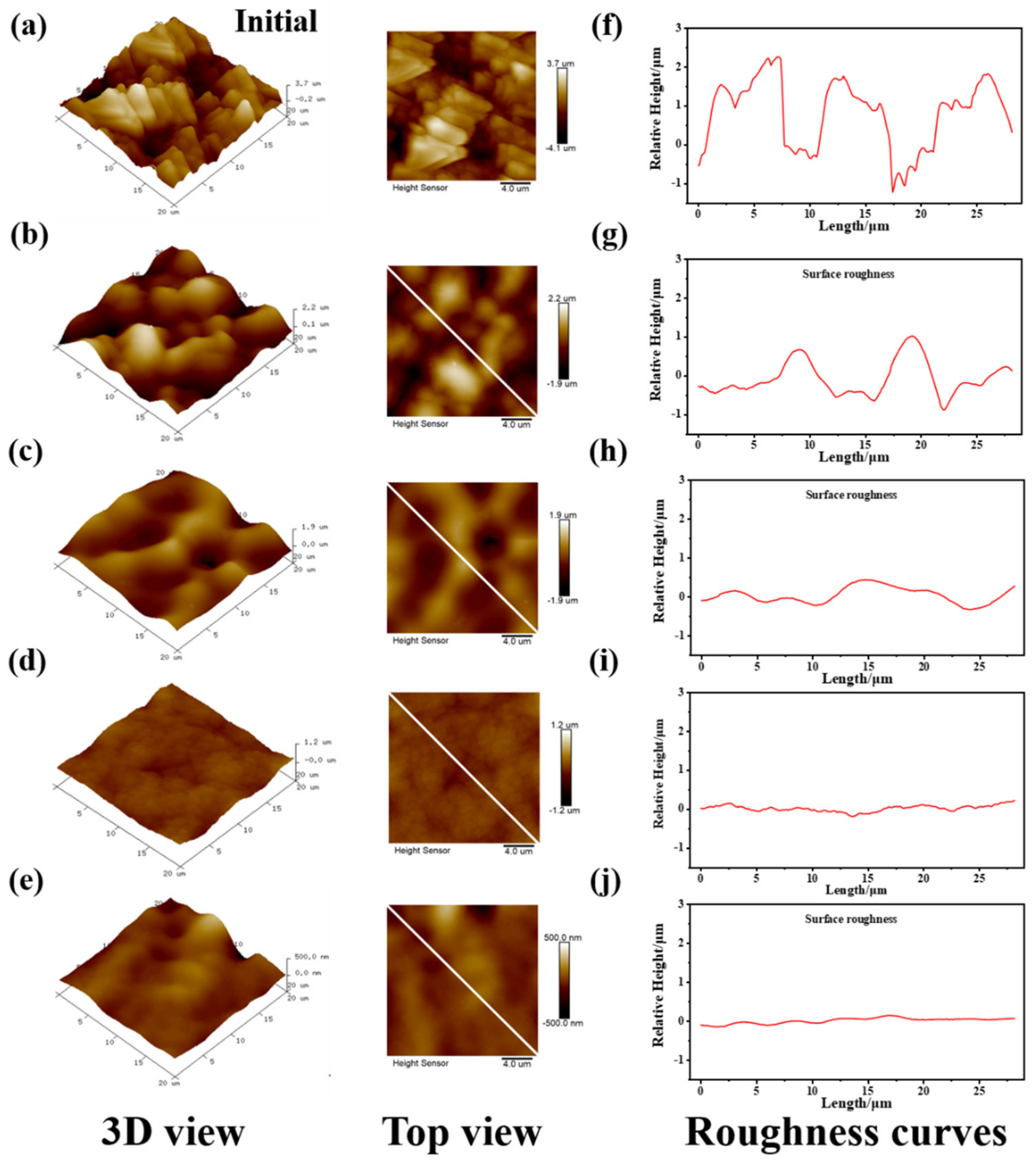
In order to further clarify the surface roughness and structure of electrolytic copper foils with different roughness, we used AFM to further examine the above electrolytic copper foil samples. The topography image and surface roughness curve of 20 × 20 μm electrolytic copper foil are shown in Figure 3. For the CF-3.6, CF-2.8, and CF-2.2 electrolytic copper foil samples with higher roughness, the AFM 3D view images show a rapidly vibrating surface texture with a deep roughness valley and a much shorter roughness wavelength (Figure 3a,b). However, with the prolongation of the duration of the electropolishing treatment, the peak of copper clusters was weakened, and the surfaces of CF-2.2, CF-1.5, and CF-1.2 electrolytic copper foils were extremely smooth and had almost no large copper clusters (Figure 3d,e). It can also be clearly seen from the roughness curves of the corresponding electrolytic copper foil samples that the curve fluctuation of CF-1.2 is the smallest, indicating that its surface uniformity is the best.
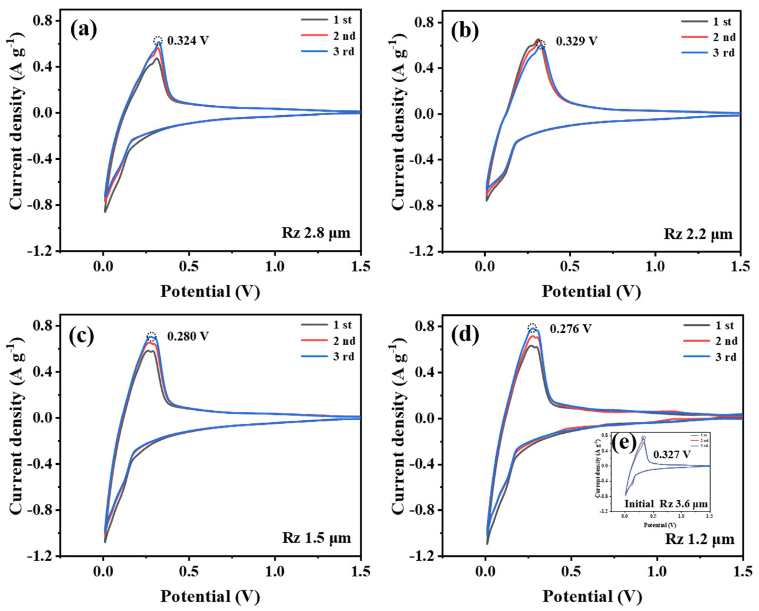
In order to verify that the optimization of roughness can indeed improve the electrochemical performance of electrolytic copper foil, we assembled coin-type half-cells using electrolytic copper foils with different roughness as the anode current collector and carried out relevant battery-performance tests. Figure 4 shows the cyclic voltammetry (CV) curves of the initial three cycles recorded at a scan rate of 0.5 mV s−1 for batteries using different electrolytic copper foils. The reduction and oxidation peaks in the curves are related to the intercalation and deintercalation processes of lithium ions in the anode materials, respectively. The good repeatability of the CV curves in the figures shows that the batteries using these electrolytic copper foils as the current collectors have good stability, and the reduction peaks are all close to 0 V [32]. Interestingly, the oxidation peaks of cells assembled with CF-3.6, CF-2.8, CF-2.2, CF-1.5, and CF-1.2 electrolytic copper foils are 0.327, 0.324, 0.329, 0.280, and 0.276 V, respectively, which shows a significant downward trend with the decrease of electrolytic copper foil roughness. Moreover, with the reduction of electrolytic copper foil roughness, the peak area of the CV curve gradually increases, indicating that reducing electrolytic copper foil roughness can also improve battery capacity.
Figure 5a shows the initial charge/discharge curves of CF@graphite from 0.01 to 3.0 V at 0.1 C current rate. CF-3.6@graphite, CF-2.8@graphite, CF-2.2@graphite, CF-1.5@graphite, and CF-1.2@graphite electrodes exhibit discharge capacities of 384.6, 393.5, 395.6, 434.1 and 433.3 mAh g−1, respectively. During the first discharge, the discharge capacity exceeded the theoretical value of pure graphite (372 mAh g−1) due to the decomposition of the electrolyte and the formation of the solid electrolyte interface (SEI) film. However, it can be clearly observed that a reduction in roughness can effectively enhance the release of graphite electrode capacity. Figure 5b shows the comparison of rate capabilities of different CF@graphite electrodes at rates from 0.2 to 3 C. It can be seen that the CF-1.2@grphite electrode with the lowest roughness of electrolytic copper foil exhibits the best rate performance, maintaining 358.7, 323.7, 268.9, and 102.5 mAh g−1 at the rates of 0.2, 0.5, 1.0, and 3.0 C, respectively. By comparison, at a rate of 3.0 C, the discharge capacities of CF-3.6@graphite, CF-2.8@graphite, CF-2.2@graphite, CF-1.5@graphite, and CF-1.2@graphite electrodes drop to 54.6, 54.5, 71.8, 75.5, and 102.5 mAh g−1, respectively.
As mentioned above, the low-roughness electrolytic copper foil has good wettability with the graphite anode slurry, which reduces the resistance of the contact surface, promotes electron transfer, and improves electrochemical performance. Figure 5c shows the cycling curves of CF@graphite electrodes with different roughness at a current rate of 0.5 C. The initial discharge capacities are 304.9, 311.6, 314.1, 317.5, and 319.5 mAh g−1 for CF-3.6@graphite, CF-2.8@graphite, CF-2.2@graphite, CF-1.5@graphite, and CF-1.2@graphite electrode, respectively, which remain at 285.0, 285.6, 294.7, 297.8, and 311.4 mAh g−1 with the capacity retention ratio of 93.4%, 91.7%, 93.8%, 93.8%, and 98.1% after 100 cycles. It is further confirmed that the battery using low-roughness electrolytic copper foil as the current collector has a higher reversible capacity and better cycling stability. Figure 5d shows the electrochemical impedance spectroscopy (EIS) curves of electrodes before cycling. The semicircle in the high-frequency region and the curves in the mid-high-frequency region correspond to the migration impedance (Rsf) of lithium ions through the SEI film and the charge transfer impedance (Rct) of the intercalation reaction, respectively. The cell with the low-roughness electrolytic copper foil as the current collector has lower total impedance. This may be due to the close contact between the low-roughness electrolytic copper foil and the graphite anode, which reduces the contact resistance at the interface, thereby increasing the rate at which the electrolytic copper foil accepts and outputs electrons in electrochemical reactions.
To verify the long-term reliability of reducing electrolytic copper foil roughness to improve the electrochemical performance of the battery, we performed ex-situ SEM observations on the samples after 100 cycles, as shown in Figure 6. Compared with the samples before cycling, after 100 cycles at 0.5 C and 2 C, the graphite electrode of electrolytic copper foil with greater roughness has more significant cracks, as shown in Figure 6f–o. This may be due to the volume expansion of the graphite anode after prolonged cycling. When the graphite anode slurry layer is deformed and cracked, the surface of the electrolytic copper foil is easily exposed to the electrolyte, which increases the corrosion of copper and the consumption of the electrolyte, thereby reducing the cycle performance and stability. In fact, almost no cracks were found in the graphite electrodes prepared from the low-roughness electrolytic copper foil, especially for CF-1.2, which proves that the low-roughness electrolytic copper foil is beneficial to the uniform coating of graphite and promotes complete contact with the electrolytic copper foil, thereby improving the cycling stability of the battery.

4. Conclusions

In summary, we reduce the roughness of electrolytic copper foil with a simple and effective electropolishing method. Electrolytic copper foils with the roughness of 3.6 μm, 2.8 μm, 2.2 μm, 1.5 μm, and 1.2 μm were used as the current collector. The graphite was used as the negative electrode, and lithium metal was used as the counter electrode to assemble a half-cell to evaluate the electrochemical performance of the electrolytic copper foil. The results show that CF-1.2 with the lowest roughness has a higher electrical conductivity and can effectively improve the uniformity of the graphite anode coating. At the same time, the contact area between the low-roughness electrolytic copper foil and the electrolyte is small, and the corrosion resistance is stronger. Using low-roughness electrolytic copper foil as the anode, the current collector exhibits higher capacity, better cycling stability, and rate performance. It is inferred that electropolishing can be used as an effective method to reduce the roughness of electrolytic copper foil to improve the overall performance of LIBs.

Author Contributions

Conceptualization and Writing-Original Draft, J.Z.; Data curation and formal analysis, D.Z.; Visualization, X.P.; Resources, C.M.; Software, K.C.; Methodology, Q.C.; Writing-review & editing, G.H.; Conceptualization, Supervision, Writing—review & editing, Y.T. All authors have read and agreed to the published version of the manuscript.

Funding

The authors gratefully acknowledge the National Natural Science Foundation of China (Grant Nos. U1802254 and 51871201), Zhejiang Provincial Natural Science Foundation of China (Grant No. LQ22E020005 and LZ22E010002), the State Key Laboratory of Advanced Technologies for Comprehensive Utilization of Platinum Metals (SKL-SPM-202009), and China Postdoctoral Science Foundation (No. 2021M702890).

Data Availability Statement

The data presented in this study are available on request from the corresponding author.

Conflicts of Interest

The authors declare no conflict of interest.

References

  1. Chen, J.; Wang, X.; Gao, H.; Yan, S.; Chen, S.; Liu, X.; Hu, X. Rolled electrodeposited copper foil with modified surface morphology as anode current collector for high performance lithium-ion batteries. Surf. Coatings Technol. 2021, 410, 126881. [Google Scholar] [CrossRef]
  2. Fan, X.-Y.; Ke, F.-S.; Wei, G.-Z.; Huang, L.; Sun, S.-G. Sn–Co alloy anode using porous Cu as current collector for lithium ion battery. J. Alloys Compd. 2009, 476, 70–73. [Google Scholar] [CrossRef]
  3. Arai, S.; Kitamura, T. Simple Method for Fabrication of Three-Dimensional (3D) Copper Nanostructured Architecture by Electrodeposition. ECS Electrochem. Lett. 2014, 3, D7–D9. [Google Scholar] [CrossRef] [Green Version]
  4. Zhang, J.; Chen, H.; Wen, M.; Shen, K.; Chen, Q.; Hou, G.; Tang, Y. Lithiophilic 3D Copper-Based Magnetic Current Collector for Lithium-Free Anode to Realize Deep Lithium Deposition. Adv. Funct. Mater. 2021, 32, 2110110. [Google Scholar] [CrossRef]
  5. Reyter, D.; Rousselot, S.; Mazouzi, D.; Gauthier, M.; Moreau, P.; Lestriez, B.; Guyomard, D.; Roué, L. An electrochemically roughened Cu current collector for Si-based electrode in Li-ion batteries. J. Power Sources 2013, 239, 308–314. [Google Scholar] [CrossRef]
  6. Pan, C.; Chen, S.-J.; Huang, Y.-H.; Wang, L.; Luo, J.-L.; Fu, X.-Z. A facile method to fabricate lightweight copper coated polyimide film current collectors for lithium-ion batteries. J. Power Sources 2022, 528, 231207. [Google Scholar] [CrossRef]
  7. Long, J.; Liu, H.; Xie, Y.; Tang, W.; Fu, T.; Tang, Y.; Lu, L.; Ding, X.; Tang, X. Three-Dimensional Copper Foil-Powder Sintering Current Collector for a Silicon-Based Anode Lithium-Ion Battery. Materials 2018, 11, 1338. [Google Scholar] [CrossRef] [Green Version]
  8. Liu, H.; Wang, E.; Zhang, Q.; Ren, Y.; Guo, X.; Wang, L.; Li, G.; Yu, H. Unique 3D nanoporous/macroporous structure Cu current collector for dendrite-free lithium deposition. Energy Storage Mater. 2019, 17, 253–259. [Google Scholar] [CrossRef]
  9. Zhu, X.; Zhou, S.; Jiang, X.; Yao, X.; Xu, X.; Peng, A.; Wang, L.; Xue, Q. High-performances of Li4Ti5O12 anodes for lithium-ion batteries via modifying the Cu current collector through magnetron sputtering amorphous carbon. J. Alloys Compd. 2020, 830, 154682. [Google Scholar] [CrossRef]
  10. Xu, X.; Shen, K.; Wen, M.; Wu, Q.; Hou, G.; Cao, H.; Wu, L.; Zheng, G.; Tang, Y. Facile synthesis of three-dimensional Cu/Fe3O4 nanowires as binder-free anode for lithium-ion batteries. Appl. Surf. Sci. 2018, 450, 356–363. [Google Scholar] [CrossRef]
  11. Zhang, H.; Yang, Y.; Ren, D.; Wang, L.; He, X. Graphite as anode materials: Fundamental mechanism, recent progress and advances. Energy Storage Mater. 2020, 36, 147–170. [Google Scholar] [CrossRef]
  12. Wei, C.; Tang, J.; Xu, G.; Xia, S.; Ye, N.; Zhao, Y.; Yan, J. Electroless Deposition of Automatically Shedded Thin Copper Foils. ACS Appl. Mater. Interfaces 2020, 12, 28831–28839. [Google Scholar] [CrossRef] [PubMed]
  13. Qiu, X.; Yu, M.; Fan, G.; Liu, J.; Wang, Y.; Zhao, K.; Ding, J.; Cheng, F. Growing Nanostructured CuO on Copper Foil via Chemical Etching to Upgrade Metallic Lithium Anode. ACS Appl. Mater. Interfaces 2021, 13, 6367–6374. [Google Scholar] [CrossRef] [PubMed]
  14. Ding, K.; Qu, R.; Zhou, L.; Zhang, D.; Chen, J.; He, X.; Wang, L.; Wang, H.; Dou, H. In situ preparation of CuCl cubic particles on the commercial copper foil: Its significant facilitation to the electrochemical performance of the commercial graphite and its unexpected photochromic behavior. J. Alloys Compd. 2020, 835, 155302. [Google Scholar] [CrossRef]
  15. Shen, C.; Hu, G.; Cheong, L.; Huang, S.; Zhang, J.; Wang, D. Direct Observation of the Growth of Lithium Dendrites on Graphite Anodes by Operando EC-AFM. Small Methods 2017, 2, 1700298. [Google Scholar] [CrossRef]
  16. Zhang, J.; Chen, H.; Fan, B.; Shan, H.; Chen, Q.; Jiang, C.; Hou, G.; Tang, Y. Study on the relationship between crystal plane orientation and strength of electrolytic copper foil. J. Alloys Compd. 2021, 884, 161044. [Google Scholar] [CrossRef]
  17. Zhao, Y.; Liu, C.; Sun, Y.; Yi, R.; Cai, Y.; Li, Y.; Mitrovic, I.; Taylor, S.; Chalker, P.; Yang, L.; et al. 3D-structured multi-walled carbon nanotubes/copper nanowires composite as a porous current collector for the enhanced silicon-based anode. J. Alloys Compd. 2019, 803, 505–513. [Google Scholar] [CrossRef]
  18. Yang, Y.; Yuan, W.; Zhang, X.; Ke, Y.; Qiu, Z.; Luo, J.; Tang, Y.; Wang, C.; Yuan, Y.; Huang, Y. A review on structuralized current collectors for high-performance lithium-ion battery anodes. Appl. Energy 2020, 276, 115464. [Google Scholar] [CrossRef]
  19. Xia, T.; Liang, T.; Xiao, Z.; Chen, J.; Liu, J.; Zhong, S. Nanograined copper foil as a high-performance collector for lithium-ion batteries. J. Alloys Compd. 2020, 831, 154801. [Google Scholar] [CrossRef]
  20. Wen, S.; Li, Z.; Zou, C.; Zhong, W.; Wang, C.; Chen, J.; Zhong, S. Improved performances of lithium-ion batteries by conductive polymer modified copper current collector. New J. Chem. 2021, 45, 10541–10548. [Google Scholar] [CrossRef]
  21. Toigo, C.; Frankenberger, M.; Billot, N.; Pscherer, C.; Stumper, B.; Distelrath, F.; Schubert, J.; Pettinger, K.; Arbizzani, C. Improved Li4 Ti5 O12 electrodes by modified current collector surface. Electrochim. Acta 2021, 392, 138978. [Google Scholar] [CrossRef]
  22. Luo, J.; Yuan, W.; Huang, S.; Zhao, B.; Chen, Y.; Liu, M.; Tang, Y. From Checkerboard-Like Sand Barriers to 3D Cu@CNF Composite Current Collectors for High-Performance Batteries. Adv. Sci. 2018, 5, 1800031. [Google Scholar] [CrossRef] [Green Version]
  23. Xiao, J.Z.; Chen, J.; Liu, J.; Liang, T.; Zhong, S. Microcrystalline copper foil as a high performance collector for lithium-ion batteries. J. Power Sources 2019, 438, 226973. [Google Scholar] [CrossRef]
  24. Jia, S.; Wang, Y.; Liu, X.; Zhao, S.; Zhao, W.; Huang, Y.; Li, Z.; Lin, Z. Hierarchically porous CuO nano-labyrinths as binder-free anodes for long-life and high-rate lithium ion batteries. Nano Energy 2019, 59, 229–236. [Google Scholar] [CrossRef]
  25. Jeong, C.U.; Lee, S.-Y.; Kim, J.; Cho, K.Y.; Yoon, S. Embossed aluminum as a current collector for high-rate lithium cathode performance. J. Power Sources 2018, 398, 193–200. [Google Scholar] [CrossRef]
  26. Jeon, H.; Cho, I.; Jo, H.; Kim, K.; Ryou, M.-H.; Lee, Y.M. Highly rough copper current collector: Improving adhesion property between a silicon electrode and current collector for flexible lithium-ion batteries. RSC Adv. 2017, 7, 35681–35686. [Google Scholar] [CrossRef] [Green Version]
  27. Fu, Y.; Yang, Z.; Li, X.; Wang, X.; Liu, D.; Hu, D.; Qiao, L.; He, D. Template-free synthesized Ni nanofoams as nanostructured current collectors for high-performance electrodes in lithium ion batteries. J. Mater. Chem. A 2013, 1, 10002–10007. [Google Scholar] [CrossRef]
  28. Yang, H.; Xiong, F.; Wang, Y.; Jia, L.; Hao, J. Manufacturing profile-free copper foil using laser shock flattening. Int. J. Mach. Tool. Manuf. 2020, 152, 103542. [Google Scholar]
  29. Chen, G.; Yang, G.; Zhou, S.; Tawfiq, K.; Wei, H.; Wang, B. Electropolishing of surfaces: Theory and applications. Surf. Eng. 2017, 33, 149–166. [Google Scholar]
  30. Till, G.; David, S.; Ajinkya, M.; Chris, M.; Arno, K.; Gunther, R. Classification of calendering-induced electrode defects and their influence on subsequent processes of lithium-ion battery production. Enegry Technol.-Ger. 2020, 8, 1900026. [Google Scholar]
  31. Yoon, S.; Jang, H.-S.; Kim, S.; Kim, J.; Cho, K.Y. Crater-like architectural aluminum current collectors with superior electrochemical performance for Li-ion batteries. J. Electroanal. Chem. 2017, 797, 37–41. [Google Scholar] [CrossRef]
  32. Fei, X.; Dong, Z.; Gong, B.; Zhao, X. Lightweight Through-Hole Copper Foil as a Current Collector for Lithium-Ion Batteries. ACS Appl. Mater. Interfaces 2021, 13, 42266–42275. [Google Scholar] [CrossRef] [PubMed]
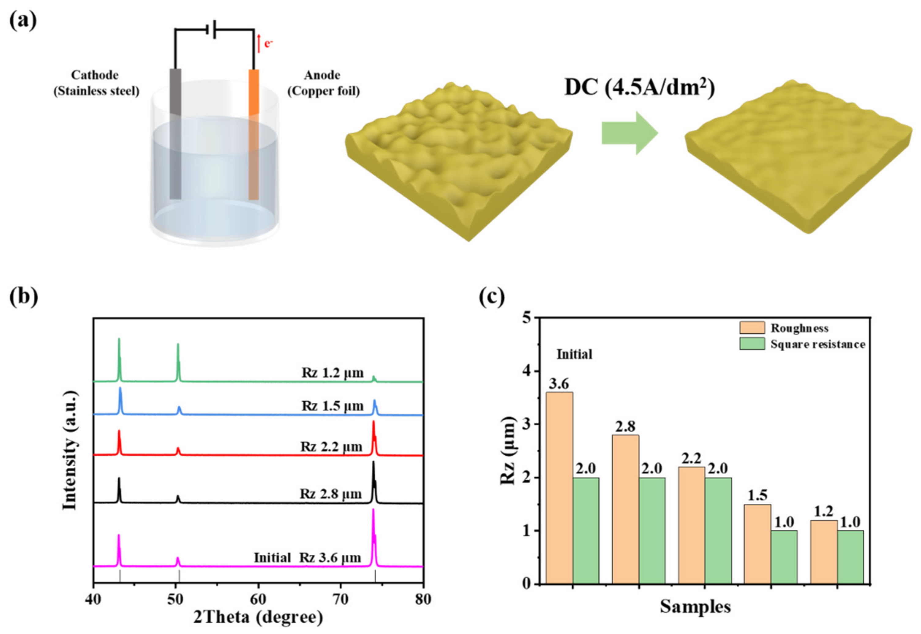
Figure 1. (a) Schematic illustration of the electropolishing process. (b) XRD for electrolytic copper foils with different surface roughness. (c) Specific roughness (Rz) values and sheet resistance of electrolytic copper foils with different roughness.
Metals 12 02110 g001
Figure 2. SEM images for electrolytic copper foils with different roughness (Rz) values: (a) CF-3.6, (b) CF-2.8, (c) CF-2.2, (d) CF-1.5, (e) CF-1.2. Contact angles and cause values between N-Methylpyrrolidone and electrolytic copper foils with different roughness. The wettability of the anode slurry and electrolytic copper foil is shown in the upper right corner of the figure: (f) CF-3.6, (g) CF-2.8, (h) CF-2.2, (i) CF-1.5, (j) CF-1.2. Cross-section optical microscopy images of graphite anode coated on electrolytic copper foils: (k) CF-3.6@graphite, (l) CF-2.8@graphite, (m) CF-2.2@graphite, (n) CF-1.5@graphite, (o) CF-1.2@graphite.
Metals 12 02110 g002
Figure 3. AFM images and surface roughness curves of electrolytic copper foils with different roughness: (a,f) CF-3.6, (b,g) CF-2.8, (c,h) CF-2.2, (d,i) CF-1.5, (e,j) CF-1.2.
Metals 12 02110 g003
Figure 4. Initial three CV curves recorded at the scan rate of 0.5 mV s−1 for batteries using electrolytic copper foils with different roughness: (a) CF-2.8-graphite, (b) CF-2.2-graphite, (c) CF-1.5-graphite, (d) CF-1.2-graphite, inset: CF-3.6-graphite.
Metals 12 02110 g004
Figure 5. Electrochemical performance of CF@graphite electrodes with different roughness: (a) Initial charge/discharge curves (b) Rate performance. (c) Cycle performance on 0.5 C from 0.01 to 3 V. (d) EIS.
Metals 12 02110 g005
Figure 6. SEM images for a surface of graphite electrode: (ae) before cycle test, (fj) after 100 cycles at 0.5 C, (ko) after 100 cycles at 2 C.
Metals 12 02110 g006
Publisher’s Note: MDPI stays neutral with regard to jurisdictional claims in published maps and institutional affiliations.