Article

Crystal Chemistry and Physical Properties of A Quaternary Intermetallic Compound, θ-(Al0.8718Cu0.0256Si0.1026)13Fe4

Brunel Centre for Advanced Solidification Technology (BCAST), Brunel University London, Uxbridge UB8 3PH, UK
*
Author to whom correspondence should be addressed.
Metals 2022, 12(12), 2112; https://doi.org/10.3390/met12122112
Submission received: 24 October 2022 / Revised: 30 November 2022 / Accepted: 4 December 2022 / Published: 8 December 2022
(This article belongs to the Section Computation and Simulation on Metals)

Abstract

:
θ-Al13Fe4 particles form as a primary Fe intermetallic compound (Fe-IMC) during the casting of commercial Al metals and alloys that inevitably contain Fe and Si as impurities. Moreover, the excellent mechanical performances of the Al-Cu alloys demand knowledge about the structural chemistry of the Fe-IMCs, including the θ-phase in the quaternary Al-Cu-Fe-Si system. Here, we investigate the stability, crystal structure, and electronic and mechanical properties of the Cu and Si co-doped θ-phase using a first-principles density-functional theory approach. The calculations reveal high stability of a quaternary θ-phase with chemical composition (Al0.8718Cu0.0256Si0.1026)13Fe4 at ambient conditions. Thermodynamics and statistical analysis show a broad range of Si content in the structure at the casting temperature. The Cu and Si (co-)doping enhances the bulk modulus of the compounds. The calculated bulk modulus of the quaternary θ-phase is 129 GPa. The findings help characterize the θ-phase in the quaternary Al-Si-Fe-Cu system and understand the formation of the θ-phase and related phase transformations in the various Al alloys during casting.

1. Introduction

Commercial aluminum metals and alloys inevitably contain impurities such as iron (Fe) and silicon (Si) [1,2,3]. Fe has low solubility in aluminum (<0.05 wt%), which persuades its existence in the forms of iron intermetallic compounds (Fe-IMCs), including the primary θ-Al13Fe4. During casting, first θ-Al13Fe4 particles form and then they transform to other Fe-IMCs with the decreasing temperature [2,4,5,6,7,8,9]. Si is often added to Al alloys to improve the mechanical performance of the cast parts [1,2,7,8]. Si may dissolve into the Fe-IMCs [4,6,7,8,9,10]. These Fe-IMCs have nontrivial impacts on the mechanical performances of the cast parts [2,7,8,9,10,11]. It is, thus, essential to remove the Fe-IMCs in Al-metal/alloys during liquid handling and to cast processes in the industry [2,8,9]. This becomes even more important for recycling Al scraps for our circular economy [12,13,14]. To reach these goals, knowledge about the formation, stability and structural and physical properties of the Fe-IMCs, particularly the primary θ-Al13Fe4 phase in various Al alloys, is crucial.
There have been many experimental efforts on the formation and phase transformations in Al-based metals and alloys during casting [2,5,6,7,8,9,10], as well as the thermal stability [15,16,17,18] and its crystal structure [19,20] and the physical properties [21] of θ-Al13Fe4. Crystalographically, θ-Al13Fe4 is rich in variation. It has a monoclinic lattice with space group C2/m (nr. 12). The experimental lattice parameters are, a = 15.492 Å, b = 8.078 Å, c = 11.471 Å and β = 107.69° [19]. This cell contains 102 atoms (78 Al and 24 Fe) in 20 different Wyckoff positions (15 Al and 5 Fe). Each Fe atom has nine to eleven Al neighbors; meanwhile, the Al atoms have 10 to 12 neighbors, with the exception of Al2, which has six neighbors with bonds shorter than 3.0 Å [19].
θ-Al13Fe4 is also the prototype of the family of θ-M13Fe4 (M = Co, Fe, Ni, Pt) [22]. Moreover, the rich volatility of the metallic species indicates the possibility of dissolving other metallic atoms into this structure to form multicomponent crystals, including the solution of the transition metals, Co, Cr, Ni, and Pt, at the Fe sites [21,23]. Experimental and theoretical studies have also found Si solution at the Al sites in θ-Al13Fe4 [2,3,4,6,7,8,9,10,11]. Moreover, to improve the mechanical performances of the cast parts, Cu is often added to produce Al-Cu alloys [1,3,15]. Experiments have revealed Cu solution in θ-Al13Fe4 [24,25].
Theoretical approaches, especially parameter-free first-principles methods, have been successfully applied to investigate the stability, structural and electronic properties of various Fe-IMCs [16,17,26,27,28]. First-principle calculations have also been used for the bulk [22,28,29,30], its surfaces [31,32], as well as the intrinsic defects in θ-Al13Fe4 [33,34]. Recently, more interest was drawn to Si [35] and Cu [36] solutions in θ-Al13Fe4.
In the present study, we investigate Si-Cu co-doping in θ-Al13Fe4 using the first-principles density-functional theory within generalized gradient approximation (DFT-GGA). Hubbard U correction was included to describe the Cu 3d electrons, which is important for adequately describing the local chemical bonding [36]. Our study reveals Cu-Si co-solution in the θ-phase, forming a stable quaternary θ-Al68Cu2Si8Fe24 at ambient conditions. Thermodynamics analysis shows the dependence of chemical compositions on preparation conditions. The calculations also provide the bulk modulus of the stable θ-phases. The findings here help us to understand the formation, stability, crystal structure, and properties of the θ-phase in the quaternary Al-Fe-Cu-Si system for the properties of cast Al alloys.

2. Methods

The previous first-principles study revealed the high stability of θ-Al76Cu2Fe24 in the ternary Al-Fe-Cu system [36]. This compound is used here as the starting point. The solid-solid reactions with Si solution at the Al sites can be defined as,
θ-Al76Cu2Fe24 + n Si − n Al = θ-(Al76-nSin)Cu2Fe24 + ΔH
The related formation energy of Si-containing configurations is,
ΔE = E(θ-(Al76-nSin)Cu2Fe24) − {E(θ-Al76Cu2Fe24) + n [E(Si) − E(Al)]}
Here ΔH is the enthalpy of the reaction (1). E(θ-(Al76-nSin)Cu2Fe24), E(θ-Al76Cu2Fe24), E(Si), and E(Al) represent the calculated total valence-electron energies of θ-(Al76-nSin)Cu2Fe24, θ-Al76Cu2Fe24, and the elemental solids Si and α-Al, respectively. The unit in Equation (2) is eV/cell. A negative value of ΔE means that the reaction (1) is exothermal and favored. At ambient conditions (T = 0 K, P = 0 Pa), the formation energy is equal to the negative value of the reaction enthalpy in Equation (1), ΔE = −ΔH, when the zero-point vibration energy term is ignored.
For the calculations, we employ a plane-wave method implemented in the first-principles code VASP (Vienna Ab initio Simulation Package) [37,38]. We also use the spin-polarized generalized gradient approximation [39] within the projector-augmented wave method [40] for the exchange and correlation energy terms. This is because the generalized gradient approximation describes the 3d transition metals well [41,42]. Considering the localized nature of the Cu 3d electrons, we employed the Hubbard U correction [43,44] with U = 4 eV, according to the previous study, to avoid the unphysical interaction of the localized Cu 3d electrons with the neighboring atoms [36,45]. The cut-off energy of the wave functions was set at 550.0 eV and the cut-off energy of the augmentation functions was 700.0 eV. These energies are significantly higher than the corresponding default values for the elements. The electronic wave functions were sampled on a 4 × 8 × 6 grid with 70–110 k-points in the irreducible Brillouin zone of the conventional cell of the θ-phase, depending on the symmetry using the Monkhorst–Pack scheme [46]. Both the lattice parameters and the coordinates of the atoms were fully relaxed. Different k-meshes and cut-off energies were used for the waves and augmentation waves, respectively. The tests showed good convergence (<1 meV/atom).

3. Results and Discussions

Using the above mentioned code and settings, the calculations produced lattice parameters for the elemental solids [47]: a = 3.039 Å for α-Al with a face-centered cubic cell (experimental value, a = 3.0325 Å at 0 K [48], the same for the rest); a = 5.468 Å for Si of the diamond-type structure (a = 5.42982 Å [48]); a = 2.831 Å for the ferromagnetic α-Fe with a body-centered cubic cell (a = 2.8607 Å [48]); and a = 3.622 Å for Cu (a = 3.6032 Å [48]). The calculated magnetic moment for α-Fe is 2.18 μB/Fe, the same as the previous work [27]. The calculated lattice parameters agree with the experimental values with deviations within 1%. The calculations also produced total valence-electron energies for these elemental solids, which will be used to study the formation energies of the related θ-phases.
Calculations for the Si solutions in the Fe sites in θ-Al76Cu2Fe24, with respect to this parent ternary compound and the elemental solids, α-Al and α-Fe, showed that the Si solution at the Fe sites is costly, with formation energies high than 0.5 eV/Si. This indicates that it is unlikely for the Si solution to form in the Fe sites in the θ-phase.

3.1. Si Solution in θ-Al76Cu2Fe24

The Al atoms at each Al site are fully replaced by Si. In this way, the symmetry of the systems is maintained. The calculations revealed non-spin-polarized solutions for all the θ-phases. The obtained results (lattice parameters, cell volume, and formation energies, according to Equation (2)) are listed in Table 1. The coordination numbers of the nearest neighbors for the Si atoms in the optimized structures are included in Table 1.
Table 1 shows the overall trends of the calculated results with the Si solutions in the Al sites in θ-Al76Cu2Fe24. There are only three configurations with Si at the Al8 (denoted as Si8, same for the rest), whereas Al9 and Al6 sites have negative formation energies (Table 1). We also employ the (n Si m) to represent the condition of the calculation; ‘n’ means the number of Si atoms, and ‘m’ the Al sites. The 4Si4 has a small positive formation energy (0.174 eV/cell). The remaining configurations have high values of positive formation energies ranging between 0.48 eV/cell and 1.50 eV/cell. The order of the stability of the stable configurations (from high to low) is 4Si8 > 4Si9 > 4Si6. This order of stability is different from that of Si solutions in pristine θ-Al78Fe24, where the configuration with 4Si9 is the most stable one [35].
The coordination of the Si atoms in the configuration of 4Si8 is similar to that of 4Si9. Each Si in the configurations has four Fe neighbors and seven Al neighbors (Table 1). In the 4Si4, each Si also has four Fe neighbors. In 4Si6, each Si atom has three Fe neighbors. The analysis indicates that each Si has three or four Fe neighbors in the stable configurations.
As shown in Table 1, the volume of the Si solutioned configurations decreases with increasing Si contents in general, with the exception of the highly unstable configuration of 4Si2. This corresponds to the smaller atomic volume of Si with respect to Al [48]. Table 1 also shows that the most stable configuration (4Si8) has the smallest volume among the configurations with the four Si solutions at the Al1 sites.
Next, we focused on the stable configurations with Si solutions at Al8, Al9 and Al6. We performed structural optimizations and total energy calculations for the Si solutions with various contents at the three Al sites. Moreover, we also investigated the configurations of the Si solutions at the mixed Al8, Al9, and Al6 sites. The obtained configurations and related formation energies for the more stable structures are shown in Figure 1.
Figure 1 shows that the formation energy decreases with the increased Si content for Si solutions at the individual Al sites and with the same order of stability, as shown in Table 1, (from high to low): Si8 > Si9 >> Si6, being consistent with the results in Table 1. The Si solutions at mixing Al8 and Al9 have the formation energies in-between those at the corresponding Al8 and Al9 sites with the same Si content.
The investigation revealed that the most stable configurations have 4Si8 and 4Si9 with the composition θ-Al68Cu2Si8Fe24. This has been justified for more arrangements with the same Si content. The next stable configuration with this composition has 4Si8 + 3Si9 + 1Si, the formation energy of which is approximately 0.16 eV/cell higher than the stable one, as shown in Figure 1.
The solutions of Si at the Al6 sites in θ-Al68Cu2Si8Fe24 produced the most stable configurations with the same Si content. The calculations showed that the formation energy increases with the Si content. The maximum Si content with negative formation energy is 12Si at the Al9, Al8, and Al6 sites. The calculations also showed that further Si solutions at the other Al sites, e.g., Al4 in θ-Al68Cu2Si8Fe24, increase the formation energy notably, indicating such solutions as being unfavored.

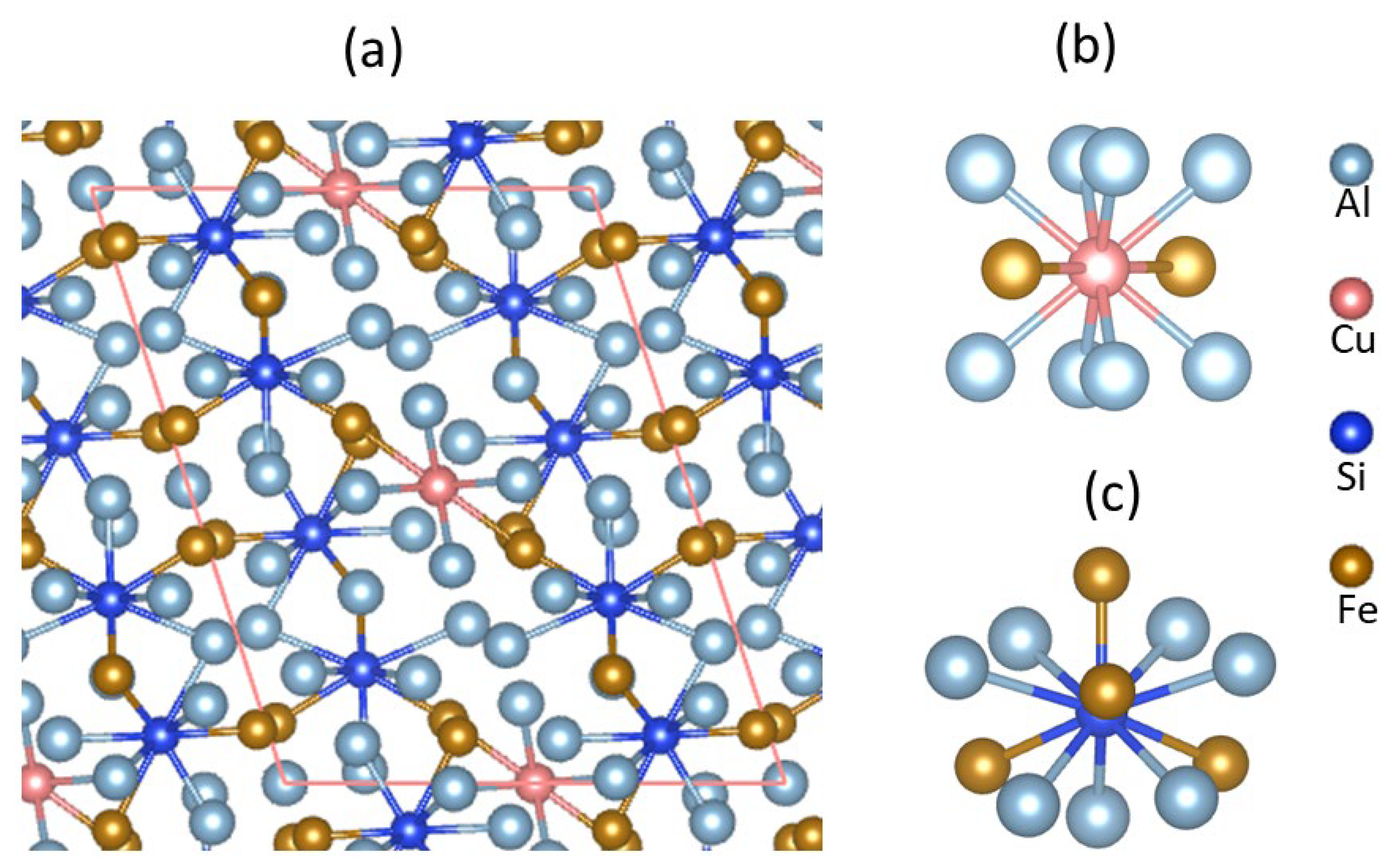
3.2. Crystal Chemistry of θ-Al68Cu2Si8Fe24

The optimized structure for the most stable θ-Al68Cu2Si8Fe24, schematically along its [010] orientation, is shown in Figure 2. The atomic coordinates are shown in Table 2.
The frame of the structure of θ-Al68Cu2Si8Fe24 is the same as that of the pristine θ-Al78Fe24 [19,33]. Here, we focus on the special Al sites, Al7 (2Cu7), Al8 (4Si8), and Al9 (4Si9), in the Cu-Si co-solutioned θ-phase. The chemical bonds of those selected atoms in the different configurations are shown in Table 3.
Table 2 and Table 3 showed that the coordination numbers of the atoms at the same site in the different compositions are the same. However, there are some subtle differences between θ-Al68Cu2Si8Fe24 and the other configurations.
The Cu7-Fe bond length is 2.61 Å in θ-Al76Cu2Fe24, which is close to that of (2.64 Å) in θ-Al68Cu2Si8Fe24. However, these Cu7-Fe bond lengths are larger than the corresponding Al7-Fe bonds (~2.46 Å) in θ-Al78Fe24 and θ-Al74Si4Fe24. Meanwhile, the Cu7-Al bonds, on average (~2.63 Å), in the Cu-containing configurations are shorter than the Al7-Al bonds in the binary Al-Fe and the ternary Al-Fe-Si compounds (~2.74 Å), as shown in Table 3. This phenomenon corresponds well to the smaller Cu volume than Al [44].

3.3. Electronic Properties of θ-Al68Cu2Si8Fe24

Using the settings in Section 2, we performed electronic band structure calculations for the stable θ-Al68Cu2Si8Fe24. The obtained electron density distributions and partial density of states (pDOS) for selected atoms and the total density of states (tDOS) are shown in Figure 3 and Figure 4, respectively.
To better understand the interatomic interactions in θ-Al68Cu2Si8Fe24, we also performed Bader charge analysis, which divides an atom into solid via the zero-flux surfaces between the atom and its surrounding atoms (δρ(r)/δr = 0) [49]. Based on the calculated electron density distribution (Figure 3), the obtained charges at the atomic sites are included in Table 2.
As shown in Figure 4, the Si 3s and 3p states are between −11.6 eV and −0.5 eV and the conduction bands. There is a valley between −0.5 eV and 0 eV, such as a pseudo-gap. The Si 3s states are positioned at the lower valence band (−11.6 eV to −6.0 eV). There are also some Si 3s states at the lower part of the conduction band. Meanwhile, the Si 3p state dominates the upper part of the valence bands and the conduction bands from 2.5 eV. There is admixing between the Si 3s and 3p states, corresponding to the sp3 hybrid.
The Cu 3d states dominate the curve with a peak at −4.5 eV and with a bandwidth of approximately 1.0 eV. This value peak is notably lower than that in pure Cu (−2.3 eV) from the first-principles calculations with Hubbard U correction and the photoemission spectrum measurements [45]. This indicates that the Cu in the structure gains electrons from the environments, which is confirmed by Bader’s charge analysis (Table 2). Moreover, the narrow bandwidth indicates the localized nature of the Cu 3d electrons, which contribute little to the chemical bonding between the Cu and the neighboring atoms.
The Fe 3d states dominate the upper part of the valence band (from −4.0 eV to −0.5 eV). A considerable density of Fe 3d states is located at the Fermi level. Such broad peaks indicate the rather delocalized nature of the Fe 3d states in the compound. The Fe 3d states are almost fully occupied, consistent with the significant gains of electrons from their neighboring atoms. This also means that Fe atoms obtain electrons from the surrounding Al atoms. The Al 3s 3p states are all over the valence and conduction bands with lower densities, corresponding to the metallic nature of the element, indicating their ionic and covalent nature. This agrees with the non-spin-polarized state for the Fe atoms.
Moreover, from Figure 3 and Figure 4, and Table 2, we obtained the following results:
(1)
Al atoms have few electrons around them, corresponding to their metallic nature, as such metals are composed of free electrons and ions. Bader’s charge analysis showed the Al atoms are positively charged with a loss of 1.1 e/Al to 1.5 e/Al (Table 2).
(2)
Cu atoms have almost spherically shaped clouds of dense electrons around them. This is due to the itinerant 3d electrons (Figure 4). Each Cu gains 1.0 e/Cu (Table 2) from neighboring Al atoms.
(3)
Fe atoms also exhibit irregularly shaped clouds of high densities, indicating interactions between Fe 3d states with neighboring atoms, including Si, Cu and Al. Bader charge analysis showed more significant electron gains for the Fe atoms with charges ranging between −2.82 e/Fe and −3.54 e/Fe, corresponding to its electronegativity value being larger than Al. Correspondingly, the Fe atoms are non-spin-polarized in the compounds.
(4)
Si atoms have high electron density around them, and they connect to Fe atoms, forming Si-Fe and Si-Fe-Cu clusters. They are negatively charged with −0.9 e/Si8 to −1.2 e/Si9 from the neighboring Al atoms.
(5)
The number of charge transfers between the atoms, Al, Cu, and Si also indicate the covalent nature of θ-Al68Cu2Si8Fe24.
In brief, electronically Cu 3d states are fully occupied and positioned approximately 4.5 eV below the Fermi level with a small bandwidth, indicating little contribution to the chemical bonding. The Fe 3d states dominate the upper valence band and the Fermi level. The Al atoms are positively charged, whereas the Si, Fe, and Cu atoms are negatively charged. This compound exhibits ionic, covalent, and metallic triple nature.

3.4. Stability and Mechanical Properties of the θ-Phases

The dependences of the total valence-electron energies on the volumes are investigated for the binary, ternary and quaternary θ-phases. Using the Murnaghan equation of states [50,51], we obtained the parameters (ground electronic energies, ground state volume, bulk modulus) of the related compounds. The obtained relation between the total valence-electron energies and volumes is plotted in Figure 5 and Table 4.
As shown in Figure 5, the energy-volume values fit well using the Murnaghan equation of states [51]. As summarized in Table 4, the solutions of the Si-Cu atoms at the Al sites decrease the volume of the pristine θ-Al13Fe4 unit cell. This corresponds to the shorter M-Al and M-Fe (M = Si or Cu) than the corresponding Al-Al and Al-Fe bonds (Table 3).
Table 4 also shows that solutions of Si or Cu enhance the bulk modulus of the θ-phases. The quaternary θ-Al68Cu2Si8Fe24 has the maximum bulk modulus (129 GPa) which is higher than that (122 GPa) of the pristine θ-Al13Fe4 and those of the ternary compounds (123 to 127 GPa).
To provide a comparison of the stability of the binary, ternary and quaternary θ-structures, we investigated their formation energies with respect to the elemental solids in a systematic way. The formation energy of a compound Al78-n-mSinCumFe24 (0 ≤ n, 0 ≤ m ≤ 2) with respect to the elemental solids, α-Al, α-Fe, Si and Cu is here defined as
ΔE(Al78-n-mSinCumFe24) = E(Al76-n-mSinCumFe24) − [(76-n-m) E(Al) + 24 E(Fe) + n E(Si) + m E(Cu)],
here, E(Al76-n-mSinCumFe24), E(Fe), E(Al), E(Si) and E(Cu) are, respectively, the calculated total energy for θ-Al76-n-mSinCumFe24, and the elemental solids, α-Al, α-Fe, Si and Cu. The calculated formation energies are shown in Table 4.
As shown in Table 4, the Si and Cu solutions in θ-Al13Fe4 form, respectively, the ternary θ-Al74Si4Fe24 and θ-Al76Cu2Fe24 compounds, are more stable than the parent binary phase. Table 4 also shows that the Si and Cu co-solution in θ-Al13Fe4 form, the quaternary θ-Al72Cu2Si4Fe24 and θ-Al68Cu2Si8Fe24, are more stable than the binary and the ternary phases, with the latter being the most stable under ambient conditions.
The calculated bulk modulus of the θ-phases provided us information about their mechanical properties. Meanwhile, for better knowledge regarding the elastic properties of these complex compounds, the related elastic constant coefficients and related phonon spectra require further investigation.

3.5. Formation Range and Stability of θ-(Al76-nSinCu2)Fe24 at Casting Temperature

The first-principles calculations showed that Si atoms prefer the Al8 and Al9 sites in the θ-phase. Meanwhile, the energy difference between the Si at the Al8 and Al at the Al9 sites is insignificant. For n = 1 in θ-(Al76-nSinCu2)Fe24, the energy difference value between the 1Si8 and 1Si9 is small (0.05 eV/cell) and increases with the increasing the Si content. The energy difference reaches its maximum value with n = 4 (0.184 eV/cell). Meanwhile, the formation energies for configurations Si at the mixed Al8 and Al9 sites with -n = 2 to 4 are in-between those at Al8 or Al9. This indicates extra freedom of Si solutions in θ-Al76Cu2Fe24 at elevated temperatures. With higher the Si concentration (n = 5 to 8), the energy differences between the 4Si8 + mSi9 configurations and the mSi8 + 4Si9 (m = 1 to 3) decrease with the Si content. For m = 1, the energy difference is 0.133 eV/cell and for m = 4 it becomes 0 eV. This analysis also means extra freedom for Si solutions in θ-Al76Cu2Fe24 with higher Si contents. Next, we discuss the stability of the Cu-Si co-solutioned θ-phase at the casting temperature.
The experiments showed that the θ-phases are formed during casting, typically at around 1000 K, at which temperature the extra freedom of the Si solutions in the Fe-IMC contributes to the free energy of the system:
ΔG = ΔHT ΔS
where ΔS = R ln w, and w is the number of configurations of the same Si content and R (= 8.617 × 10⁻⁵ eV/K) is the Boltzmann constant.
To simplify the analysis, we employed the random model to obtain the number of configurations for the θ-(Al76-nSin)Cu2Fe24. The obtained dependence of the estimated free formation energies on the Si content at 1000 K is shown in Figure 6.
Thermodynamics and statistical analysis revealed that, at the casting temperature, in a Si-poor alloy, the Si content ranges between 3.9 at.% and 6.0 at.% or n = 4 to 6 in the θ-(Al76-nSin)Cu2Fe24. The exact composition depends on the chemical environment and the formation temperature.
The present investigations revealed that the most stable configuration at ambient conditions is θ-(Al68Si8)Cu2Fe24, with Cu at the Al7 and Si at the Al8 and Al9 sites. The calculations also produced a bulk modulus to be 129 GPa for this stable configuration. The study also provided detailed information about the structural and electronic properties of this stable configuration. This obtained information is useful to characterize this phase in the cast alloys and to obtain insight into the contribution of this phase to the mechanical properties of the products.
Thermodynamics and statistical analysis revealed that the extra freedom of Si substitutions at the Al sites strongly impacts the stability and chemical composition of the formed θ-phase at the casting temperature. Using the random model for the Si at the Al8 and Al9 sites, we found that at 1000 K, the Si partial occupations at the Al8 and Al9 sites, particularly the former, are preferred. The estimated chemical compositions are θ-(Al76-nSin)Cu2Fe24 with 4 < n < 6 at 1000 K. Moreover, the configurational entropy contributions further stabilize the θ-phase. This information is helpful in investigating the formation of the θ-phase at the phase transformations of the θ-phase to other Fe-IMCs during the casting and related annealing processes of various Al-based alloys [7,52,53].

4. Conclusions

The present first-principles study revealed a quaternary compound of high stability with the chemical composition θ-Al68Si8Cu2Fe24 or θ-Al11.3333Si1.3333Cu0.3333Fe4 at ambient conditions. The calculated lattice parameters are a = 15.390 Å, b = 7.910 Å, c = 12.309 Å, β = 108.06° and volume = 1424.53 Å3/cell. The lengths of the axis and the cell volume are smaller than the corresponding axis of the binary θ-Al13Fe4. This compound exhibits a chemically ionic, metallic, and covalent triple nature. The calculated bulk modulus for this quaternary compound is 129 GPa, higher than the related binary θ-Al13Fe4 (118GPa), ternary θ-compounds θ-Al12.6667Cu0.3333Fe4 (122GPa) and θ-Al12.3333Si0.6667Fe4 (124 GPa). The obtained information helps characterize the θ-phase in the quaternary Al-Fe-Si-Cu system and the role of this phase in the mechanical performance of the related cast Al-based alloys. The analysis also showed that configurational entropy enhances the stability of the partially Si solutions in this phase, forming θ-(Al76-nSin)Cu2Fe24 with 4 < n < 6 at 1000 K. This information is helpful in investigating the formation of the θ-phase at the phase transformations of the θ-phase to other Fe-IMCs during casting and related annealing processes.

Author Contributions

Conceptualization, C.F.; methodology, C.F.; software, C.F.; validation, C.F.; formal analysis, C.F.; investigation, C.F.; resources, C.F.; data curation, C.F.; writing—original draft preparation, C.F.; writing—review and editing, C.F., Z.Q., M.S., Z.F.; visualization, C.F.; supervision, Z.F.; project administration, Z.Q.; funding acquisition, Z.F. All authors have read and agreed to the published version of the manuscript.

Funding

This research was funded by EPSRC (UK) under grant number EP/N007638/1 and EP/S005102/1.

Conflicts of Interest

The authors declare no conflict of interest.

References

  1. Mondolfo, L.F. Aluminum Alloys: Structure and Properties; Butterworths: London, UK, 1976. [Google Scholar]
  2. Zhang, L.F.; Gao, J.W.; Nana, L.; Damoah, W.; Robertson, D.G. Removal of iron aluminum: A review. Miner. Process. Extr. Metall. Rev. 2012, 33, 99–157. [Google Scholar] [CrossRef]
  3. Glazoff, M.V.; Khvan, A.V.; Zolotorevsky, V.S.; Belov, N.A.; Dinsdale, A.T. Casting Aluminum Alloys, Their Physical and Mechanical Metallurgy; Butterworth-Heinemann: Oxford, UK; Cambridge, MA, USA, 2019. [Google Scholar]
  4. Stefániay, V.; Griger, A.; Turmezey, T. Intermetallic phases in the aluminium-side corner or the AlFeSi-alloy system. J. Mater. Sci. 1987, 22, 539–546. [Google Scholar] [CrossRef]
  5. Shabestari, S.G. The effect of iron and manganese on the formation of intermetallic compounds in aluminum-silicon alloys. Mater. Sci. Eng. A 2004, 383, 289–298. [Google Scholar] [CrossRef]
  6. Marker, M.C.J.; Skolyszewska-Kühberger, B.; Effenberger, H.S.; Schmetterer, C.; Richter, K.W. Phase equilibria and structural investigations in the system Al-Fe-Si. Intermetallics 2011, 19, 1919–1929. [Google Scholar] [CrossRef]
  7. Que, Z.P.; Mendis, C.L. Formation of θ-Al13Fe4 and the multi-step phase transformations to α-Al8Fe2Si, β-Al5FeSi and δ-Al4FeSi2 in Al-20Si-0.7Fe alloy. Intermetallics 2020, 127, 106960. [Google Scholar] [CrossRef]
  8. Que, Z.; Wang, Y.; Fan, Z. Formation of the Fe-Containing Intermetallic Compounds during Solidification of Al-5Mg-2Si-0.7Mn-1.1Fe Alloy. Met. Mater. Trans. A 2018, 49, 2173–2181. [Google Scholar] [CrossRef] [Green Version]
  9. Taylor, J. Iron-Containing Intermetallic Phases in Al-Si Based Casting Alloys. Procedia Mater. Sci. 2012, 1, 19–33. [Google Scholar] [CrossRef] [Green Version]
  10. Khalifa, W.; Samuel, F.H.; Gruzleski, J.E. Iron intermetallic phases in the Al corner of the Al-Si-Fe system. Metall. Mater. Trans. A 2003, 34, 807–825. [Google Scholar] [CrossRef]
  11. Krendelsberger, N.; Weitzer, F.; Schuster, J.C. On the Reaction Scheme and Liquidus Surface in the Ternary System Al-Fe-Si. Met. Mater. Trans. A 2007, 38, 1681–1691. [Google Scholar] [CrossRef]
  12. Schlesinger, M.E. Aluminum Recycling; Taylor & Francis Group: Oxfordshire, UK, 2017. [Google Scholar]
  13. Gesing, A.; Berry, L.; Dalton, R.; Wolanski, R. Assuring continued recyclability of automotive aluminum alloys: Grouping of wrought alloys by color, X-ray adsorption and chemical composition-based sorting. In Proceedings of the TMS 2002 Annual Meeting: Automotive Alloys and Aluminum Sheet and Plate Rolling and Finishing Technology Symposia, Seattle, WA, USA, 17–21 February 2002; pp. 3–17. [Google Scholar]
  14. Raabe, D.; Ponge, D.; Uggowitzer, P.J.; Roscher, M.; Paolantonio, M.; Liu, C.L.; Antreckowitsch, H.; Kozenschnik, E.; Seidmann, D.; Gault, B.; et al. Making sustainable aluminum by recycling scrap: The science of “dirtyȍ alloys”. Prog. Mater. Sci. 2022, 128, 100947. [Google Scholar] [CrossRef]
  15. Yang, W.-C.; Gao, F.; Ji, S.-X. Formation and sedimention of Fe-rich intermetallics in Al-Si-Cu-Fe alloy. Trans. Nonferrous Met. Soc. China 2015, 25, 1704–1724. [Google Scholar] [CrossRef] [Green Version]
  16. Sundman, B.; Ohnuma, I.; Dupin, N.; Kattner, U.R.; Fries, S.G. An assessment of the entire Al–Fe system including D03 ordering. Acta Mater. 2009, 57, 2896–2908. [Google Scholar] [CrossRef]
  17. Zienert, T.; Fabrichnaya, O. Experimental investigation and thermodynamic assessment of the Al-Fe system. J. Alloy. Compd. 2018, 743, 795–811. [Google Scholar] [CrossRef]
  18. Li, X.L.; Scherf, A.; Heilmaier, M.; Stein, F. The Al-rich part of the Fe-Al phase diagram. JPEDAV 2016, 37, 162–173. [Google Scholar] [CrossRef] [Green Version]
  19. Grin, J.; Burkhard, U.; Ellner, M.; Peters, K. Refinement of the Fe4Al13 structure and its relationship to the quasihomogical homeotypical structures. Z. Kristal. 1994, 209, 479–487. [Google Scholar] [CrossRef]
  20. Saitoh, K.; Yokosawa, T.; Tanaka, M.; Tsai, A.P. Structural studied of monoclinic approximants of Al13Fe4 and τ2-inflated Al13Co4 by the high-angle annular dark-field method. J. Electron Microsc. 1999, 48, 105–114. [Google Scholar] [CrossRef]
  21. Popčević, P.; Smontara, A.; Ivkov, J.; Wencka, M.; Komelj, M.; Jeglič, P.; Vrtnik, S.; Bohnar, M.; Jagličić, Z.; Baer, B.; et al. Anisotropic physical properties of the Al13Fe4 complex intermetallic and its ternary derivative Al13(Fe, Ni)4. Phys. Rev. B 2010, 81, 184203. [Google Scholar] [CrossRef]
  22. Jeglič, P.; Vrtnik, S.; Bobnar, M.; Klanjšek, M.; Bauer, B.; Gille, P.; Grin, Y.; Haarmann, F.; Dolinšek, J. M-Al-M groups trapped in cages of Al13M4 (M = Co, Fe, Ni, Ru) complex intermetallic phases as seen via NMR. Phys. Rev. B 2010, 82, 104201. [Google Scholar] [CrossRef]
  23. Lafaye, P.; Oishi, K.; Bourdon, M.; Harvey, J.-P. Crystal chemistry and thermodynamic modelling of the Al13(Fe,TM)4 solid solutions (TM = Co, Cr, Ni, Pt). J. Alloy. Compd. 2022, 920, 165779. [Google Scholar] [CrossRef]
  24. Freiburg, C.; Grushko, B. An Al13Fe4 phase in the Al-Cu-Fe alloy system. J. Alloys Compd. 1994, 210, 149–152. [Google Scholar] [CrossRef]
  25. Genba, M.; Sugiyama, K.; Hiraga, K.; Yokoyama, Y. Crystalline structure of a Cu-substituted λ-Al13Fe4 phase by means of the anomalous X-ray scattering. J. Alloy. Compd. 2002, 342, 143–147. [Google Scholar] [CrossRef]
  26. Becker, H.; Bulut, N.; Kortus, J.; Leineweber, A. β-Al4.5FeSi: Hierarchical crystal and defect structure: Reconciling experimental and theoretical evidence including the influence of Al vs. Si ordering on the crystal structure. J. Alloy. Compd. 2022, 911. [Google Scholar] [CrossRef]
  27. Fang, C.M.; Que, Z.P.; Fan, Z. Crystal chemistry and electronic structure of the β-AlFeSi phase from first-principles. Solid State Chem. 2021, 299, 122199. [Google Scholar] [CrossRef]
  28. Zienert, T.; Leineweber, A.; Fabrichnaya, O. Heat capacity of Fe-Al intermetallics: B2-FeAl, FeAl2, Fe2Al5 and Fe4Al13. J. Alloy. Compd. 2017, 725, 848–859. [Google Scholar] [CrossRef]
  29. Singh, V.K.; Krajčí, M.; Sarkar, S.; Bala, M.; Barman, S.; Sadhukhan, P.; Gloskovskii, A.; Feuerbacher, M.; Barman, S.R. Electronic structure of β-Al3Mg2 and Al13Fe4 complex metallic alloys. Phys. Rev. B 2022, 105, 205107. [Google Scholar] [CrossRef]
  30. Van Alboom, A.; Lemmens, B.; Breitbach, B.; De Grave, E.; Cottenier, S.; Verbeken, K. Multi-method identification and characterization of the intermetallic surface layers of hot-dip Al-coated steel: FeAl 3 or Fe 4 Al 13 and Fe 2 Al 5 or Fe 2 Al 5+x. Surf. Coat. Technol. 2017, 324, 419–428. [Google Scholar] [CrossRef]
  31. Ledieu, J.; Gaudry, Ė.; Loli, L.N.; Villaseca, S.A.; de Weerd, M.C.; Hahne, M.; Gille, P.; Dubois, J.M.; Fournée, V. Structural investigation of the (010) surface of the Al13Fe4 catalyst. Phys. Rev. Lett. 2013, 110, 076102. [Google Scholar] [CrossRef] [Green Version]
  32. Armbrüster, M.; Kovnir, K.; Friedrich, M.; Teschner, D.; Wowsnick, G.; Hahne, M.; Gille, P.; Szentmiklósi, L.; Feuerbacher, M.; Heggen, M.; et al. Al13Fe4 as a low-cost alternative for palladium in heterogeneous hydrogenation. Nat. Mater. 2012, 11, 690–693. [Google Scholar] [CrossRef] [Green Version]
  33. Fang, C.M.; Dinsdale, A.T.; Que, Z.P.; Fan, Z. Intrinsic defects in and electronic properties of θ-Al13Fe4: An ab initio DFT study. J. Phys. Mater. 2019, 2, 015004. [Google Scholar] [CrossRef]
  34. Dinsdale, A.; Fang, C.; Que, Z.; Fan, Z. Understanding the Thermodynamics and Crystal Structure of Complex Fe Containing Intermetallic Phases Formed on Solidification of Aluminium Alloys. JOM 2019, 71, 1731–1736. [Google Scholar] [CrossRef]
  35. Fang, C.; Que, Z.; Dinsdale, A.; Fan, Z. Si solution in θ-Al13Fe4 from first-principles. Intermetallics 2020, 126, 106939. [Google Scholar] [CrossRef]
  36. Fang, C.; Souissi, M.; Que, Z.; Fan, Z. Crystal Chemistry and Electronic Properties of the Al-Rich Compounds, Al2Cu, ω-Al7Cu2Fe and θ-Al13Fe4 with Cu Solution. Metals 2022, 12, 329. [Google Scholar] [CrossRef]
  37. Kresse, G.; Hafner, J. Ab initio molecular-dynamics simulation of the liquid-metal-amorphous-semiconductor transition in germanium. Phys. Rev. B 1994, 49, 14251–14269. [Google Scholar] [CrossRef] [PubMed]
  38. Kresse, G.; Furthmüller, J. Efficiency of ab-initio total energy calculations for metals and semiconductors using a plane-wave basis set. Comput. Mater. Sci. 1996, 6, 15–50. [Google Scholar] [CrossRef]
  39. Perdew, J.P.; Burke, K.; Ernzerhof, M. Generalized gradient approximation made simple. Phys. Rev. Lett. 1996, 77, 3865. [Google Scholar] [CrossRef] [Green Version]
  40. Blöchl, P.E. Projector augmented-wave method. Phys. Rev. B Condens. Matter Mater. Phys. 1994, 50, 17953–17979. [Google Scholar] [CrossRef] [Green Version]
  41. Fang, C.M.; van Huis, M.A.; Sluiter, M.H.F.; Zandbergen, H.W. Stability, structure and electronic properties of γ-Fe23C6 from first-principles. Acta Mater. 2010, 58, 2968–2977. [Google Scholar] [CrossRef]
  42. Fang, C.M.; Sluiter, M.H.F.; van Huis, M.A.; Ande, C.K.; Zandbergen, H.W. Origin of Predominance of Cementite among Iron Carbides in Steel at Elevated Temperature. Phys. Rev. Lett. 2010, 105, 055503. [Google Scholar] [CrossRef] [Green Version]
  43. Hubbard, J. Electron correlations in narrow energy bands. Proc. R. Soc. Lond. Ser. A Math. Phys. Sci. 1963, 276, 238–257. [Google Scholar] [CrossRef]
  44. Liechtenstein, A.I.; Anisimov, V.; Zaanen, J. Density-functional theory and strong interactions: Orbital ordering in Mott-Hubbard insulators. Phys. Rev. B 1995, 52, R5467–R5470. [Google Scholar] [CrossRef]
  45. Souissi, M.; Fang, C.M.; Sahara, R.; Fan, Z. Formation energies of θ-Al2Cu phase and precursor Al-Cu compounds: Importance of on-site Coulomb repulsion. Comp. Mater. Sci. 2021, 194, 110461. [Google Scholar] [CrossRef]
  46. Monkhorst, H.J.; Pack, J.D. Special points for Brillouin-zone integrations. Phys. Rev. B 1976, 13, 5188. [Google Scholar] [CrossRef]
  47. Wyckoff, R.W.G. The Structure of Crystals; Reinhold Publishing Corporation: New York, NY, USA, 1963. [Google Scholar]
  48. Arblaster, J. Selected Values of the Crystallographic Properties of the Elements; ASM International: Materials Park, OH, USA, 2018. [Google Scholar]
  49. Bader, R.F.W. A Bond Path: A Universal Indicator of Bonded Interactions. J. Phys. Chem. A 1998, 102, 7314–7323. [Google Scholar] [CrossRef]
  50. Murnaghan, F.D. The Compressibility of Media under Extreme Pressures. Proc. Natl. Acad. Sci. USA 1944, 30, 244–247. [Google Scholar] [CrossRef] [Green Version]
  51. Tyuterev, V.G.; Vast, N. Murnaghan’s equation of state for the electronic ground energy. Comp. Mater. Sci. 2006, 38, 250–353. [Google Scholar] [CrossRef]
  52. Que, Z.; Wang, Y.; Mendis, C.L.; Fang, C.; Xia, J.; Zhou, X.; Fan, Z. Understanding Fe-Containing Intermetallic Compounds in Al Alloys: An Overview of Recent Advances from the LiME Research Hub. Metals 2022, 12, 1677. [Google Scholar] [CrossRef]
  53. Que, Z.; Fang, C.; Mendis, C.L.; Wang, Y.; Fan, Z. Effects of Si solution in θ-Al13Fe4 on phase transformation between Fe-containing intermetallic compounds in Al alloys. J. Alloy. Compd. 2023, 932. [Google Scholar] [CrossRef]
Figure 1. The calculated formation energies on Si contents (n) in θ-Al76-nCu2SinFe24 with respect to θ-Al76Cu2Fe24 and the elemental solids Al and Si (Equation (2). In the figure, the (n Si m) was used to represent the condition of the calculation. ‘n’ means the number of Si atoms, and ‘m’ the Al sites. In details, the marks represent the formation energies for the configurations with (the order of) Si atoms at the corresponding Al sites: The black filled spheres represent the formation energies relating to that Si atoms first occupy the Al8 sites and gradually the Al9 sites secondly, and the Al6 at last, the red spheres that Si atoms occupy the Al9 sites first and gradually the Al8 sites secondly, the blue spheres that Si first occupies the Al6 sites and gradually the Al8 sites secondly, and the Al9 at last. The yellow spheres represent the formation energies with the configurations with Si atoms at the Al8 and Al9 sites in a mixed way. The green sphere represents the formation energy of the 4Si8, 3Si9 and 1Si6 configuration.
Metals 12 02112 g001
Figure 2. Schematic structure of θ-Al68Cu2Si8Fe24 along its [010] projection (a). The schematic coordination of Cu (b) and Si (c) is shown, respectively. The pink lines in (a) represent a-axis (parallel) and c-axis (upwards) of the unit cell.
Metals 12 02112 g002
Figure 3. Electron density distributions in θ-Al68Cu2Si8Fe24 with electron density iso-surfaces (the yellow clouds, ρ0(r) = 0.045e/Å3). The meaning of the spheres is the same as Figure 2. The Si-Fe-Si clusters are indicated by the pink lines.
Metals 12 02112 g003
Figure 4. Partial density of states (pDOS) of the selected atoms in and the total density of states (tDOS) of θ-Al68Cu2Si8Fe24. The black lines for the pDOS of atoms represent s-characters, red p-characters and green 3d-characters. The vertical dotted line represents the Fermi level (at zero eV). We observed that the Fermi level is dominated by Fe 3d states.
Metals 12 02112 g004
Figure 5. The relationships between the total valence-electron energies on the cell volumes. The dotted lines represent the fitting according to the Murnaghan equation of states [50,51].
Metals 12 02112 g005
Figure 6. The relation between the assessed formation energy at 1000 K and the Si content using the random model for Si at Al8 and Al9 sites when n< 8 and at Al6 when -n > 8. The related lowest formation energies at 0 K are included for comparison.
Metals 12 02112 g006
Table 1. The calculated results (lattice parameters, atomic coordinates, cell volumes, coordination numbers (CNN), Bader’s charges at the Si sites (q) and formation energies according to Equation (2) for Si solutions at the Al sites. The Wyckoff sites are fully replaced by Si and thus, the symmetry of the systems is the same as that of the θ-Al13Fe4 (space group, C2/m) [19].
Si-SitesLocal Sym.Lattice Parameters and Volume
a(Å), b(Å), c(Å), β(°); V3)
CNN(Si)q(e/Si)ΔE
(eV/Cell)
θ-Al76Cu2Fe24-15.501, 7.928, 12.459, 108.15; 1455.08--0.00
4Si at Al14i, m15.446, 7.978, 12.346, 108.24; 1444.983Fe,7Al−0.79+0.48
4Si at Al24i, m15.449, 7.909, 12.540, 108.18; 1455.642Fe, 10Al−0.27+0.95
4Si at Al34i, m15.373, 7.995, 12.541, 109.31; 1454.382Fe, 10Al−0.59+1.25
4Si at Al44i, m15.412, 7.930, 12.403, 107.90; 1442.544Fe, 1Si, 6Al−0.77+0.17
4Si at Al54i, m15.228, 7.992, 12.532, 107.60; 1453.682Fe, 10Al−0.64+1.45
4Si at Al64i, m15.446, 7.967, 12.356, 108.37; 1443.113Fe, 7Al−0.66−0.22
4Si at Al84i, m15.454, 7.906, 12.385, 107.97; 1439.444Fe, 7Al−0.88−0.63
4Si at Al94i, m15.454, 7.926, 12.395, 108.27; 1441.694Fe, 7Al−1.18−0.45
8Si at Al108j, 115.421, 7.959, 12.385, 109.18; 1435.653Fe, 9Al−0.88+1.41
8Si at Al118j, 115.419, 7.958, 12.289, 107.70; 1436.543Fe, 9Al−0.85+1.41
8Si at Al128j, 115.275, 7.943, 12.376, 107.01; 1436.023Fe, 9Al−0.70+1.45
8Si at Al138j, 115.249, 7.955, 12.518, 108.78; 1437.563Fe, 1Cu, 8Al−0.52+1.41
8Si at Al148j, 115.461, 7.957, 12.295, 108.21; 1436.782Fe, 1Si, 9Al−0.79+0.92
4Si at Al154g, 215.422, 7.891, 12.481, 108.09; 1443.704Fe, 8Al−0.46+0.50
Table 2. Calculated results for θ-Al68Cu2Si8Fe24. The space group is C2/m (nr. 12). The calculated lattice parameters are a = 15.390 Å, b = 7.910 Å, c = 12.309 Å, β = 108.06°.
Label
Sites
Coordinates of Atoms
x, y, z
Interatomic Distances (Å)q(e/atom)
Al1, 4i0.0657, 0.0000, 0.1709Al1-3Fe: 2.47, 2.50, 2.53; -1Si: 2.48;
-6Al: 2.79(×2); 2.81(×2); 2.84(×2)
+1.24
Al2, 4i0.3212, 0.0000, 0.2759Al2-2Fe: 2.41(×2);
-10Al: 2.85(×2), 2.92(×2), 2.98(×2); 3.03(×2); 3.09(×2)
+1.17
Al3, 4i0.2320, 0.0000, 0.5323Al3-4Fe: 2.41, 2.55, 3.13(×2); -1Si: 2.81
-9Al: 2.66, 2.76(×2), 2.85(×2), 2.88(×2); 2.90(×2)
+1.07
Al4, 4i0.0740, 0.0000, 0.5784Al4-4Fe: 2.51, 2.56(×2), 2.57; -1Si: 2.48
-6Al: 2.49, 2.66(×3), 2.76(×2)
+1.33
Al5, 4i0.2378, 0.0000, 0.9503Al5-4Fe: 2.39, 2.41, 3.05(×2); -2Si: 2.66, 2.74;
-8Al: 2.74(×2), 2.76(×2), 2.87(×2), 2.90(×2)
+1.49
Al6, 4i0.4801, 0.0000, 0.8323Al6-3Fe: 2.41, 2.49(×2); -1Si: 2.51;
-6Al: 2.79(×2), 2.80(×2), 2.84(×2)
+1.34
Cu7, 2c0.5000, 0.0000, 0.5000Cu7-2Fe: 2.64(×2);
-8Al: 2.57(×4), 2.66(×4)
−1.00
Si8, 4i0.3089, 0.0000, 0.7716Si8-4Fe: 2.42(×2), 2.46, 2.49;
-7Al: 2.51, 2.62(×2), 2.66(×2), 2.74, 2.81
−0.91
Si9, 4i0.0800, 0.0000, 0.7823Si9-4Fe: 2.38, 2.44(×2), 2.61;
-7Al: 2.48(×2), 2.63(×2), 2.66, 2.67(×2)
−1.19
Al10, 8j0.1849, 0.2172, 0.1094Al10-3Fe: 2.49(×2), 2.64; -1Si: 2.66;
-8Al: 2.61, 2.74, 2.76, 2.79, 2.82(×2), 2.90, 2.98
+1.23
Al11, 8j0.3684, 0.2131, 0.1090Al11-3Fe: 2.47, 2.49, 2.68; -1Si: 2.63;
-8Al: 2.61, 2.76, 2.77, 2.79, 2.82, 2.83, 2.87, 2.92
+1.26
Al12, 8j0.1767, 0.2206, 0.3352Al12-3Fe: 2.46, 2.55, 2.61; -1Si: 2.62;
-8Al: 2.68, 2.81, 2.82, 2.85, 2.90(×3), 3.09
+1.22
Al13, 8j0.4906, 0.2221, 0.3344Al13-3Fe:2.45,2.55, 2.61; -1Cu:2.66; -1Si:2.67
-7Al: 2.68, 2.76, 2.83, 2.84, 2.90, 2.96,3.03
+1.34
Al14, 8j0.3660, 0.2056, 0.4758Al14-2Fe: 2.46, 2.49; -1Cu: 2.57;
-9Al: 2.66, 2.68(×2), 2.76, 2.85, 2.88, 2.90, 2.92, 2.96,(3.25)
+1.09
Al15, 4g0.0000, 0.2505, 0.0000Al15-4Fe: 2.48(×4);
-8Al: 2.76(×2), 2.77(×2), 2.80(×2), 2.84(×2)
+1.32
Fe1, 4i0.0782, 0.0000, 0.3762Fe1-1Si: 2.61;
-10Al: 2.46(×2), 2.47, 2.51, 2.55 (×3), 2.57,2.92(×2)
−2.91
Fe2, 4i0.3937, 0.0000, 0.6322Fe2-1Cu: 2.64; -1Si: 2.46;
-8Al: 2.41(×2), 2.45(×2), 2.46(×2), 2.55(×2)
−3.54
Fe3, 4i0.0900, 0.0000, 0.9792Fe3-1Fe: 2.97; -1Si: 2.38;
-9Al: 2.41, 2.48(×2), 2.49(×2), 2.50, 2.53, 2.68(×2)
−3.14
Fe4, 4i0.3986, 0.0000, 0.9786Fe4-1Fe: 3.00; -1Si: 2.49;
-9Al: 2.39, 2.47(×2),2.48(×2),2.49(×2),2.64(×2)
−3.42
Fe5, 8j0.3185, 0.3048, 0.2738Fe5-1Fe: 3.09; -2Si: 2.42, 2.44;
-9Al: 2.41, 2.49(×3), 2.56, 2.61(×2), 3.05, 3.13
−2.82
Table 3. Comparison of the local coordination for the selected atoms in the pristine, Cu or/and Si solutioned and Si-Cu co-solutioned θ-phase.
Siteθ-Al78Fe24θ-Al76Cu2Fe24θ-Al74Si4Fe24θ-Al68Cu2Si8Fe24
M7, 2cAl7-2Fe: 2.47(×2)
-8Al: 2.69(×4),2.80(×4)
Cu7-2Fe: 2.61(×2)
-8Al: 2.49(×4),2.80(×4)
Al7-2Fe: 2.46(×2)
-8Al: 2.69(×4),2.79(×4)
Cu7-2Fe: 2.64(×2);
-8Al: 2.57(×4), 2.66(×4)
M8, 4iAl8-4Fe:2.47(×2), 2.61,2.70
-7Al: 2.56, 2.67(×4),
2.81(×2)
Al8-4Fe:2.47(×2),2.58,2.63
-7Al: 2.55, 2.66(×2),
2.67(×2), 2.79(×2)
Al8-4Fe:2.48(×2),2.59, 2.66
-7Al:2.54, 2.64(×2),
2.68(×2), 2.77, 2.84
Si8-4Fe: 2.42(×2), 2.46, 2.49
-7Al: 2.51, 2.62(×2),
2.66(×2), 2.74, 2.81
M9, 4iAl9-4Fe:2.46,2.49(×2),2.86
-7Al: 2.53, 2.54,2.63(×2),
2.67(×3)
Al9-4Fe:2.49,2.50(×2),2.75
-7Al: 2.52 (×2), 2.52 (×2),
2.69, 2.70(×2)
Si9-4Fe: 2.37, 2.42(×2), 2.77
-7Al:2.51(×2),2.62(×2),
2.66 (×3)
Si9-4Fe: 2.38, 2.44(×2), 2.61
-7Al: 2.48(×2), 2.63(×2),
2.66,2.67(×2)
Table 4. The obtained results for the related configurations using the Murnaghan equation of state. V0 represents the optimized volume, E0 the energy, B0 the bulk modulus and B0′ the first derivative. The formation energies (ΔEform) with respects to the elemental solids according to Equation (3) also included.
CompositionV03/Cell)E0(eV/Cell)B0(GPa)B0′ΔEform (eV/cell)
in () kJ/mol
θ-Al78Fe241466.4−523.54121.84.3−33.52(−31.7)
θ-Al76Cu2Fe241457.2−521.10122.54.3−33.84(−32.0)
θ-Al74Si4Fe241450.8−530.42124.34.4−33.69(−31.9)
θ-Al72Cu2Si4Fe241439.6−528.45127.34.2−34.24(−32.4)
θ-Al68Cu2Si8Fe241424.6−535.34129.24.4−34.65(−32.8)
Publisher’s Note: MDPI stays neutral with regard to jurisdictional claims in published maps and institutional affiliations.

