1. Introduction
Austenitic steels are among the most common structural materials for nuclear power engineering. Chromium-nickel austenitic steels are currently used as fuel element cladding and other structural parts of nuclear reactors. They have a number of attractive properties—increased heat resistance, resistance to radiation and helium embrittlement (up to radiation doses of about 100 dpa), high corrosion resistance, lack of viscous brittle transition at low temperatures, etc. [
1,
2,
3,
4,
5]. However, there are some disadvantages such as the appreciable radiation swelling (more than 6%) and the tendency to the helium embrittlement at radiation doses above 100 dpa. Another problem with these steels is their high activation after prolonged operation under irradiation conditions in a nuclear reactor. A high level of induced radioactivity will persist for more than 1000 years. This is determined by the presence of such highly activated elements as Ni, Nb, Mo, and Co in the steels composition.
Generation IV nuclear reactors, which are designed for a wider temperature range and longer fuel campaigns (compared to Gen. III reactors) and higher radiation doses (more than 110 dpa) need new structural materials with higher resistance to heat, radiation and radiation swelling. The concept of low-activation structural materials [
5,
6,
7], i.e., materials for which the induced radioactivity drops over 50–100 years to a level that allows their safe processing, significantly limits the possibility of using alloying elements in steels. It implies that Fe, Mn, V, W, Ti, Ta, Zr, and C are acceptable low-activation elements, while the content of Ni, Cu, Nb, Mo, Co, Al, N, and O should be reduced to the minimum possible values.
Promising low-activation structural materials for nuclear reactors are 9–12% Cr ferritic-martensitic steels of the EUROFER, F82H, CLAM, RUSFER types [
1,
2,
3,
8,
9] and chromium-manganese (Ni free) austenitic steels of the Fe-12Cr-(20-25)Mn system [
5,
6,
7,
10,
11,
12]. Significant progress has been made to date in the development and comprehensive study of the microstructure and mechanical properties of ferritic-martensitic steels [
1,
2,
3]. It has been shown that these steels have significantly lower values of radiation swelling (including high radiation doses) compared to the chromium-nickel austenitic steels and a number of other attractive properties [
1,
2,
3,
9,
10]. The development of low-activation chromium-manganese austenitic steels was started at the end of the 20th century and continued in the early 2000s [
5,
6,
7,
10,
11,
12,
13,
14]. In [
5,
6,
7,
10,
11,
12,
13], an advantage of these steels over the chromium-nickel steels was shown in terms of their short-term and long-term mechanical properties. Later, however, the interest decreased and the studies dealing with the topic were not so numerous [
15,
16,
17]. It should also be noted that an important merit of the austenitic steels as fcc materials is the absence of a tendency to low temperature embrittlement in contrast to bcc materials.
The experiments on irradiation of low-activation chromium-manganese austenite [
13] revealed a tendency towards pore formation due to the radiation-stimulated γ-α transformation, which is largely determined by the austenite stability. In these steels, the latter can be enhanced by increasing the content of Mn and C and by limiting the content of Cr and other ferrite-stabilizing elements. It should be underlined that when designing the compositions of such steels, it is necessary to avoid the formation of the σ-phase (Fe-Cr), which can precipitate during heat treatment and during long-term holding in certain temperature ranges and contribute to the loss of steel ductility [
5,
12,
13].
It is known [
4,
18,
19,
20,
21] that the resistance of the austenitic steels to radiation swelling can be improved by forming a high density of defects, twin boundaries and disperse particles. A large number of the latter can be achieved by aging or thermomechanical treatments in the case where sufficient amounts of carbon and carbide formers are available in the solid solution.
The aim of this work is to develop a new low-activation austenitic steel with a high content of manganese and carbide-forming elements and to study the microstructure, mechanical properties, and fracture after its solution treatment and cold rolling.
2. Materials and Methods
A 2.5-kg steel ingot of the following composition: Fe–29Mn–12Cr–W–Si–Ta–Ti–V–Zr–0.25C, wt. %, was melted in a vacuum induction furnace. The target manganese content of the steel was increased compared to known analogues [
5,
6,
7,
10,
11,
12,
13], and the carbon content was near the upper limit for known compositions to improve the austenite stability. The content of the elements with a high tendency to carbide formation (Ti, V, Zr, Ta and W) was increased. To meet the low-activation requirement, the content of such high-activation elements as Ni, Cu, Nb, Mo, Co, Al was minimized.
The elemental composition was studied by a Shimadzu LAB CENTER XRF-1800 X-ray fluorescence spectrometer (Shimadzu, Kyoto, Japan), in an ISKROLINE 300 K optical emission spectrometer (ISKROLINE, St. Petersburg, Russia), and in an Octane Elect Super (EDAX, Mahwah, New Jersey, United States) X-ray microanalysis attachment to an Apreo 2 S Scanning Electron Microscope (SEM, Thermo Fisher Scientific, Waltham, MA, USA). After melting, the ingot was homogenized at 1100 °C for 2 h followed by hot forging and hot rolling at 1100 °C. Then it was solution treated (ST) at 1100 °C for 1 h followed by air cooling. Multi-pass cold rolling (CR) was performed on a 2-roll mill at T = 22 °C to the strain degree of ε = 20%. The microstructure and the elemental and phase compositions of the steel were studied after its ST and CR treatments.
The phase content of the steel was determined by X-ray diffraction (XRD) performed in a DRON-7 X-ray diffractometer (Bourevestnik JSC, St. Petersburg, Russia) using Co Kα radiation. The Bragg-Brentano symmetric geometry was used in an angular range of 2θ = 25–115° with a scanning step of 0.05°. The exposure time at each point was 10 s. The X-ray diffractograms were processed by the method of full-profile analysis (Rietveld method).
The microstructural characterization was performed using an Apreo 2 S SEM (Thermo Fisher Scientific, Waltham, MA, USA) equipped with a Field Emission Gun (FEG) and a Tescan MIRA 3 LMU FEG SEM (TESCAN ORSAY HOLDING, Brno, Czech Republic). A Pegasus Integrated EDS-EBSD system with the Octane Elect Super and Velocity Super detectors (EDAX) were used with the Apreo 2 S SEM. An Oxford Instruments Nordlys F EBSD detector (Oxford Instruments, High Wycombe, UK) and an energy dispersive X-ray (EDX) microanalysis system with an Ultim MAX 40 detector was used for the EBSD and EDX investigations with the Tescan MIRA 3 LMU SEM.
The samples for the SEM examination were prepared by mechanical polishing followed by ion milling as a final polishing step. The latter was performed in a Technoorg Linda SEMPrep 2 system (Technoorg Linda Co. Ltd, Budapest, Hungary). The EBSD data were obtained with step sizes of 2 µm for the area of 1 mm2, 1 µm for the area of 3600 µm2 and 0.1 µm for the area of 30 × 20 µm2. The microstructure analysis was carried out by the Oxford Instruments AZtec software (version 3.1, Oxford Instruments, High Wycombe, UK) using the results obtained on the Tescan MIRA 3 and by the EDAX OIM Analysis software (version 8.6) and EDAX Apex software (version 2.1) using the results obtained on the Apreo 2 S.
The boundaries with the misorientation angles of 2° < θ ≤ 10° and θ > 10° were taken to be low- (LABs) and high-angle boundaries (HABs), respectively. The boundaries with a misorientation of ˂2° were neglected. The average grain size was taken as the equivalent circle diameter of a region with the same orientation and HABs.
The studies by Transmission Electron Microscopy (TEM) were conducted using a JEOL JEM-2100 electron microscope (JEOL Ltd., Akishimam Tokio, Japan) at an accelerating voltage of 200 kV in the TEM and Scanning Transmission Electron Microscopy (STEM) modes. Thin foils were prepared by electropolishing in an electrolyte containing 450 mL of orthophosphoric acid and 50 g of chromic anhydride. The dislocation density was calculated by the linear intercept method from bright-field TEM images. The average transverse dimensions of the twins and the particle sizes (diameter) were also estimated. The EBSD and TEM images after CR were taken in the longitudinal section.
The mechanical tension tests were carried at a strain rate of ≈2 × 10⁻³ s−1 at room temperature (20 °C) and at 650 °C (close to the maximum nuclear reactor operating temperature) using dog-bone samples with the gage length of 13 mm and the gage section of 2 × 1 mm2. The samples were cut from the section parallel to the rolling plane and subjected to tension in the rolling direction. The high temperature tensile tests were carried out in a vacuum of ≈7 × 10⁻³ Pa. The fracture surfaces of the samples after the tensile tests were studied by the Apreo 2 S SEM.
4. Discussion
In this paper, a new low-activation chromium-manganese austenitic steel with an increased manganese content compared to known analogues [
5,
6,
7,
10,
11,
12,
13] is investigated. The carbon content in it is 0.26%, which is close to the maximum values for similar steels. The content of strong carbide-forming elements (Ti, V, Ta, W, and Zr) is higher than in the analogues. These differences in the elemental composition predetermine the structure and phase state of the steel and its mechanical behavior (including high-temperature performance).
Primarily, an increased Mn content and a sufficiently high C content increase the austenite stability. According to the Scheffler’s diagram [
11,
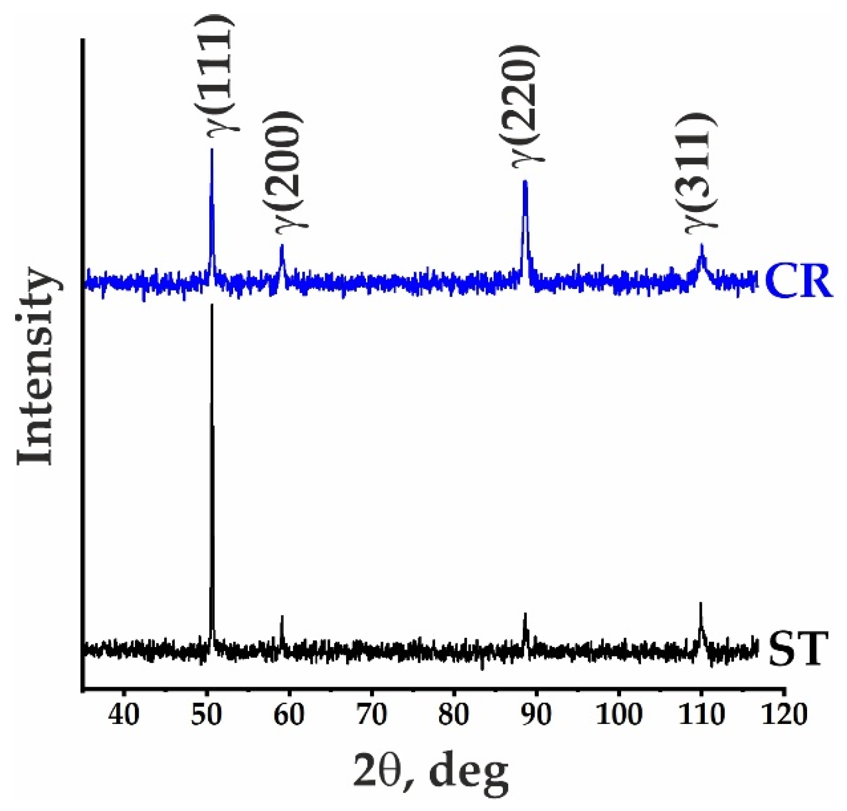
16] in its modified form for high manganese (Ni free) steels, the Ni equivalent = 22.2, and the Cr equivalent = 12.7. This determines the position of the studied composition in the single-phase austenitic region sufficiently far from the boundaries of both martensitic and ferritic regions. The increased austenite stability is confirmed by the obtained experimental results. Neither after the ST nor CR treatments there are any phases except for the austenite and an insignificant amount of the MC and M
23C
6 carbides.
As noted in [
13], the tendency of steels to radiation swelling under irradiation conditions largely depends on the austenite stability, therefore, a more stable chromium-manganese austenite may have lower values of radiation swelling compared to the known analogues; however, additional studies are needed to confirm this assumption. The calculations of nuclear-physical characteristics [
28] showed that a stable chromium-manganese austenite may have a lower tendency to helium embrittlement compared to the stable chromium-nickel austenite in the Fe–16Cr–19Ni–2Mo–2Mn–Nb–Ti–B type steel used as an advanced structural material for the fuel cladding shells in the reactors in Russia. It should also be noted that the increased stability of austenite makes it possible to consider the steel studied in this work as a promising structural material for nuclear fusion reactors.
Low-activation austenitic steels are generally studied after their ST and (or) CR treatments [
6,
7,
10,
11,
12,
13]. In contrast to the low-activation ferritic-martensitic steels [
1,
2,
3,
8,
9,
29,
30,
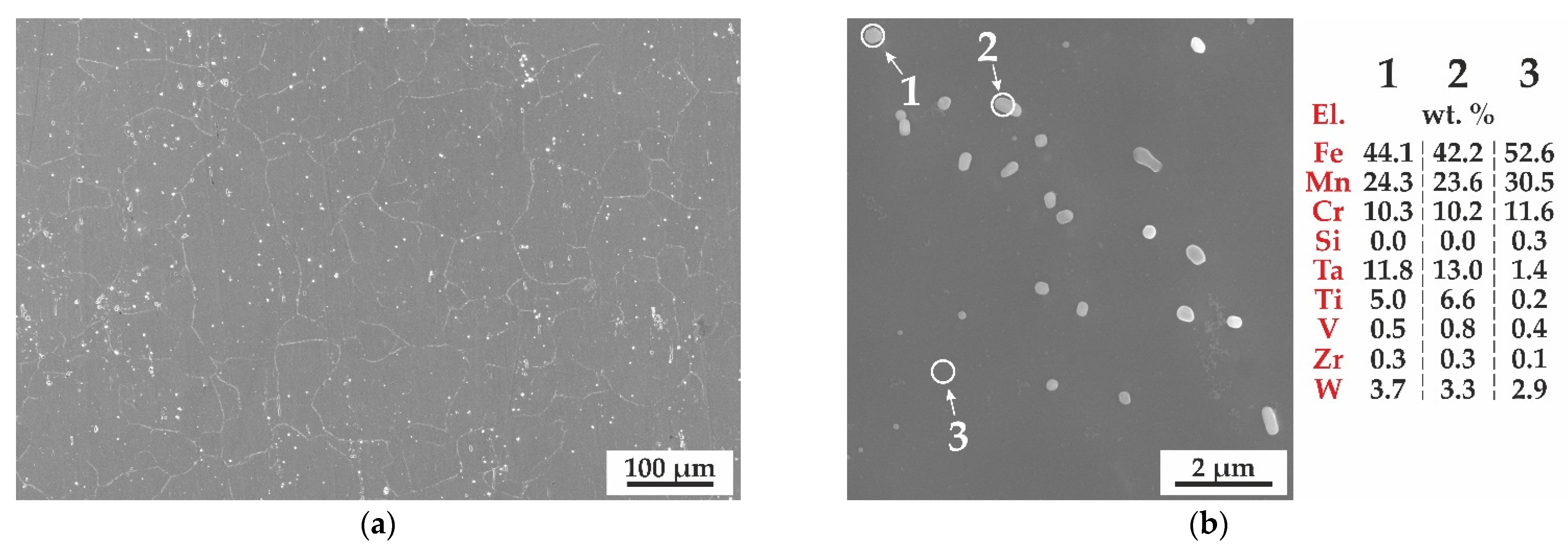
31], no heat or special thermomechanical treatments are applied to precipitate the disperse particles. In the present work an increased content of strong carbide-forming elements with a carbon content of 0.26% resulted in the formation of complexly alloyed dispersed particles of the MC type (M = Ti, Ta, V, W, Zr and Si) with a volume fraction of ≈1.2% with a mean size of 1.1 µm and M
23C
6 particles in the steel. Note that the volume fraction could be further increased by special treatments (aging or thermomechanical treatments), favoring a precipitation of new nanosized particles. It was shown earlier [
18,
19,
29,
30,
31], that nanoscale particles pin the dislocation substructure of steels and contribute to an increase in their strength properties by increasing the efficiency of dispersion and substructural strengthening. A higher volume fraction of nanoscale particles can have a positive effect on the steel resistance to radiation swelling under irradiation conditions [
18,
19]. The effects of special treatments and irradiation will be studied in the near future.
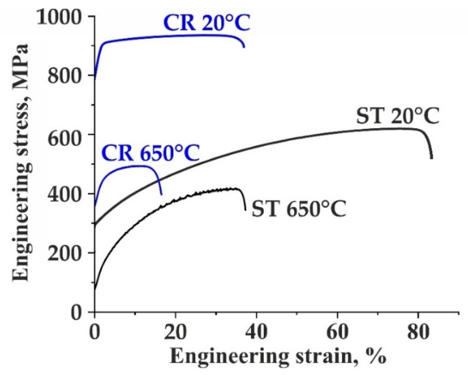
The strength properties of the steel (
Table 2) are comparable with those of the known analogues or exceed them [
7,
12] with the exception of Fe-20Mn–12Cr–Ti–W–V–P–B complexly alloyed steel subjected to CR [
7]. At the same time, the plastic properties of the new steel are 1.5–3 times higher than those of the known analogues (
Table 2). Based on the structural studies, the advanced strength and plastic properties of the new steel have been attributed to a higher efficiency of dispersion and substructural strengthening and a high (29%) content of manganese. The latter provides a sufficiently low stacking fault energy (25 mJ/m
2) and contributes to the twinning-induced plasticity effect under tension at 20 °C.
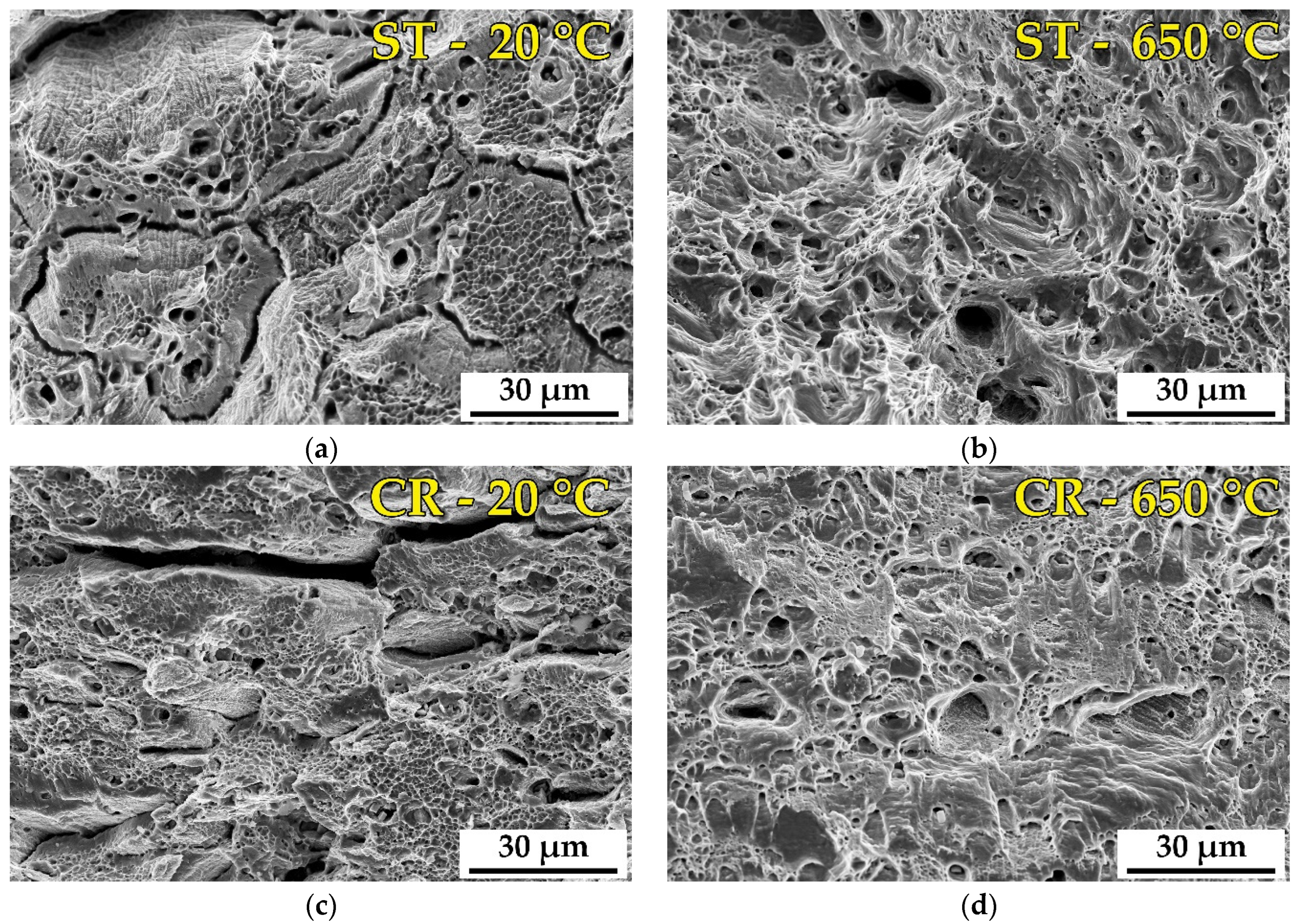
The fracture mechanism of the steel is structure sensitive and is controlled by the treatment mode (ST or CR), on the one hand, and by the tensile test temperature (20 and 650 °C), on the other hand. At room temperature tests, it is the ductile intercrystalline fracture (along with the transgranular ductile dimple fracture) which is likely to favor a higher plasticity of the ST steel over that of the CR steel. In the former, relatively soft/plastic austenite grains seem to be more easily deformed than the grain boundaries strengthened by the second-phase particles and impurity atom segregations. During tensile tests at 20 °C, this provides a higher stress concentration near the grain boundaries and an intensive formation of intercrystalline fracture canyons. After CR, due to the formation of a highly defective twin microstructure significantly (more than 2 times) increasing the steel strength properties and decreasing its plasticity compared to the ST treated steel. The number of stress concentrators inside the matrix grains becomes larger and the stress distributions along the grain boundaries and in the grain bulk become comparable.
Author Contributions
Conceptualization, I.L. and V.C.; methodology, I.L. and N.P.; formal analysis, E.M., V.L. and A.K.; investigation, S.A., N.P., K.A. and E.M.; writing—original draft preparation, I.L.; writing—review and editing, I.L., N.P., S.A. and V.C.; visualization, S.A. and K.A.; supervision, V.C.; project administration, I.L. All authors have read and agreed to the published version of the manuscript.
Institutional Review Board Statement
Not applicable.
Informed Consent Statement
Not applicable.
Data Availability Statement
Data is contained within the article.
Acknowledgments
The research was carried out with the equipment of Tomsk Regional Core Shared Research Facilities Center of National Research Tomsk State University (center was supported by the Ministry of Science and Higher Education of the Russian Federation) and Share Use Centre “Nanotech” of the ISPMS SB RAS.
Conflicts of Interest
The authors declare no conflict of interest.
References
- Was, G.S.; Petti, D.; Ukai, S.; Zinkle, S. Materials for future nuclear energy systems. J. Nucl. Mater. 2019, 527, 151837. [Google Scholar] [CrossRef]
- Pascal, Y. Structural Materials for Generation IV Nuclear Reactors; Kindle Edition; Woodhead Publishing Series in Energy: Cambridge, UK, 2020; p. 644. [Google Scholar]
- Odette, G.R.; Zinkle, S.J. Structural Alloys for Nuclear Energy Applications; Elsevier: Amsterdam, The Netherlands, 2019; p. 655. [Google Scholar] [CrossRef]
- Sagaradze, V.V.; Uvarov, A.I. Strengthening and Properties of Austenitic Steels; RIO UrB RAS: Ekaterinburg, Russia, 2013; p. 720. ISBN 978-5-7691-2334-4. (In Russian) [Google Scholar]
- Ivanov, L.I.; Platov, Y.M. Radiation Physics of Metals and Its Applications; Intercontakt Nauka: Moscow, Russia, 2022; p. 300. ISBN 5-902063-03-5. (In Russian) [Google Scholar]
- Onozuka, M.; Saida, T.; Hirai, S.; Kusuhashi, M.; Sato, I.; Hatakeyama, T. Low-activation Mn–Cr austenitic stainless steel with further reduced content of long-lived radioactive elements. J. Nucl. Mater. 1998, 255, 128–138. [Google Scholar] [CrossRef]
- Klueh, R.L.; Maziasz, P.J. Tensile and Microstructural Behavior of Solute-modified Manganese-stabilized Austenitic Steels. Mater. Sci. Eng. A 1990, 127, 17–31. [Google Scholar] [CrossRef]
- Kohyama, A.; Hishinuma, A.; Kohno, Y.; Shiba, K.; Sagara, A. The development of low activation ferritic steels for Fusion application. Sci. Rep. RITU 1997, 45, 137–141. [Google Scholar]
- Polekhina, N.A.; Litovchenko, I.Y.; Almaeva, K.V.; Tymentsev, A.N.; Chernov, V.M.; Leontyeva-Smirnova, M.V. Microstructure, Structural-Phase Transformations, and Mechanical Properties of Low-Activation 12% Chromium Ferritic-Martensitic Steel EK-181 Depending on the Treatment Conditions. Inorg. Mater. 2022, 13, 1247–1260. [Google Scholar] [CrossRef]
- Suzuki, Y.; Saida, T.; Kudough, F. Low activation austenitic Mn-steel for in-vessel fusion materials. J. Nucl. Mater. 1998, 258–263, 1687–1693. [Google Scholar] [CrossRef]
- Klueh, R.L.; Maziasz, P.J.; Lee, E.H. Manganese as an Austenite Stabilizer in Fe-Cr-Mn-C Steels. Mater. Sci. Eng. A 1988, 102, 115–124. [Google Scholar] [CrossRef]
- Demina, E.V.; Prusakova, M.D.; Roshchin, V.V.; Vinogradova, N.A.; Orlova, G.D. Reduced Activation Fe–Cr–Mn Austenitic Steels for Nuclear Power Plants. Inorg. Mater. Appl. Res. 2010, 1, 115–124. [Google Scholar] [CrossRef]
- Demina, E.V.; Ivanov, L.I.; Platov, Y.M.; Prusakova, M.D.; Eikholtser, S.R.; Tolochko, M.B.; Garner, F.A. Radiation Creep and Phase Instability of Low-Activation Austenitic Steel 12 Cr–20 Mn–W under Neutron Irradiation in the FFTF Fast Reactor. Inorg. Mater. Appl. Res. 2011, 2, 457–460. [Google Scholar] [CrossRef]
- Sahin, S.; Ubeyli, M. A Review on the Potential Use of Austenitic Stainless Steels in Nuclear Fusion Reactors. J. Fusion Energ. 2008, 27, 271–277. [Google Scholar] [CrossRef]
- Eissa, M.M.; El-kameesy, S.U.; El-Fiki, S.A.; Ghali, S.N.; El Shazlyc, R.M.; Saeed, A. Attenuation capability of low activation-modified high manganeseaustenitic stainless steel for fusion reactor system. Fusion Eng. Des. 2016, 112, 130–135. [Google Scholar] [CrossRef]
- Saeed, A.; El-Shazly, R.M.; Ghali, S.N.; El-khamisy, S.Y.; El-Moneem El-fiki, S.A.; Eissa, M.M. Low Activation-Modified High Manganese-Nitrogen Austenitic Stainless Steel for Fast Reactor Pressure Vessel Cladding. Nucl. Sci. 2018, 3, 45–51. [Google Scholar] [CrossRef]
- Mahmoudiniya, M.; Kheirandish, S.; Asadi Asadabad, M. High temperature tensile properties of new Fe-Cr-Mn developed steel. Mater. Sci. Eng. A 2017, 14, 47–57. [Google Scholar] [CrossRef]
- Shin, J.H.; Kim, H.-S.; Kong, B.S.; Subramanian, G.O.; Hong, S.; Lee, H.J.; Jang, C. Development of thermo-mechanical processing to form high density of uniformly distributed nanosized carbides in austenitic stainless steels. Mater. Sci. Eng. A 2020, 775, 138986. [Google Scholar] [CrossRef]
- Shin, J.H.; Kong, B.S.; Jeong, C.; Eom, H.J.; Jang, C.; Shao, L. Evaluation of radiation resistance of an austenitic stainless steel with nanosized carbide precipitates using heavy ion irradiation at 200 dpa. Nucl. Eng. And Tech. 2022, in press. [Google Scholar] [CrossRef]
- Velikodnyi, A.N.; Voyevodin, V.N.; Kalchenko, A.S.; Karpov, S.A.; Kolodiy, I.V.; Tikhonovsky, M.A.; Tolstolutskaya, G.D.; Garner, F.A. Impact of nano-oxides and injected gas on swelling and hardening of 18Cr10NiTi stainless steel during ion irradiation. J. Nucl. Mater. 2022, 565, 153666. [Google Scholar] [CrossRef]
- Meric de Bellefon, G.; Robertson, I.M.; Allen, T.R.; van Duysen, J.-C.; Sridharan, K. Radiation-resistant nanotwinned austenitic stainless steel. Scripta Mater. 2019, 159, 123–127. [Google Scholar] [CrossRef]
- Li, C.M.; Sommer, F.; Mittemeijer, E.J. Characteristics of the γ→α transformation in Fe–Mn alloys. Mater. Sci. Eng. A 2002, 325, 307–319. [Google Scholar] [CrossRef]
- JMatPro. Practical Software for Materials Properties. Available online: https://www.sentesoftware.co.uk/jmatpro (accessed on 30 December 2021).
- Ghazani, M.S.; Eghbali, B. Characterization of the hot deformation microstructure of AISI 321 austenitic stainless steel. Mater. Sci. Eng. A 2018, 730, 380–390. [Google Scholar] [CrossRef]
- Akkuzin, S.; Litovchenko, I.; Polekhina, N.; Almaeva, K.; Kim, A.; Moskvichev, E.; Chernov, V. Effect of Multistage High Temperature Thermomechanical Treatment on the Microstructure and Mechanical Properties of Austenitic Reactor Steel. Metals 2022, 12, 63. [Google Scholar] [CrossRef]
- Nikulin, I.; Kaibyshev, R. Deformation behavior and the Portevin-Le Chatelier effect in a modified 18Cr–8Ni stainless steel. Mater. Sci. Eng. A 2011, 528, 1340–1347. [Google Scholar] [CrossRef]
- Kuhn, H.; Medlin, D. ASM Handbook: Mechanical Testing and Evaluation; ASM International: Russel, OH, USA, 2000; Volume 8, p. 998. ISBN 978-0-87170-389-7. [Google Scholar]
- Blokhin, A.I.; Chernov, V.M. Nuclear Physical Properties of Austenitic Nickel and Manganese Steels under Neutron Irradiation in Nuclear Fission (Fast) and Fusion Reactors. Phys. At. Nucl. 2021, 84, 1272–1284. [Google Scholar] [CrossRef]
- Klueh, R.L.; Hashimoto, N.; Maziasz, P.J. New nano-particle-strengthened ferritic/martensitic steels by conventional thermomechanical treatment. J. Nucl. Mater. 2007, 367–370, 48–53. [Google Scholar] [CrossRef]
- Yin, S.; Liu, Y.; Zhao, F. Effect of thermomechanical treatment on MX phase precipitation behavior in CLAM steel. Fusion Eng. Des. 2021, 173, 112785. [Google Scholar] [CrossRef]
- Xu, Y.; Li, W.; Wang, M.; Zhang, X.; Wu, Y.; Min, N.; Liu, W.; Jin, X. Nano-sized MX carbonitrides contribute to the stability of mechanical properties of martensite ferritic steel in the later stages of long-term aging. Acta Mater. 2019, 175, 148–159. [Google Scholar] [CrossRef]
Figure 1.
XRD patterns of new steel in ST and CR states.
Figure 2.
SEM EBSD orientation map with HABs and LABs, denoted by black and white lines, respectively (a), histograms of grain size (equivalent circle diameter) distribution (b), and grain misorientation distribution of ST steel (c).
Figure 3.
SEM SE (secondary electrons) overview image (a), magnified SEM SE image with elemental composition of some dispersed particles and matrix (b).
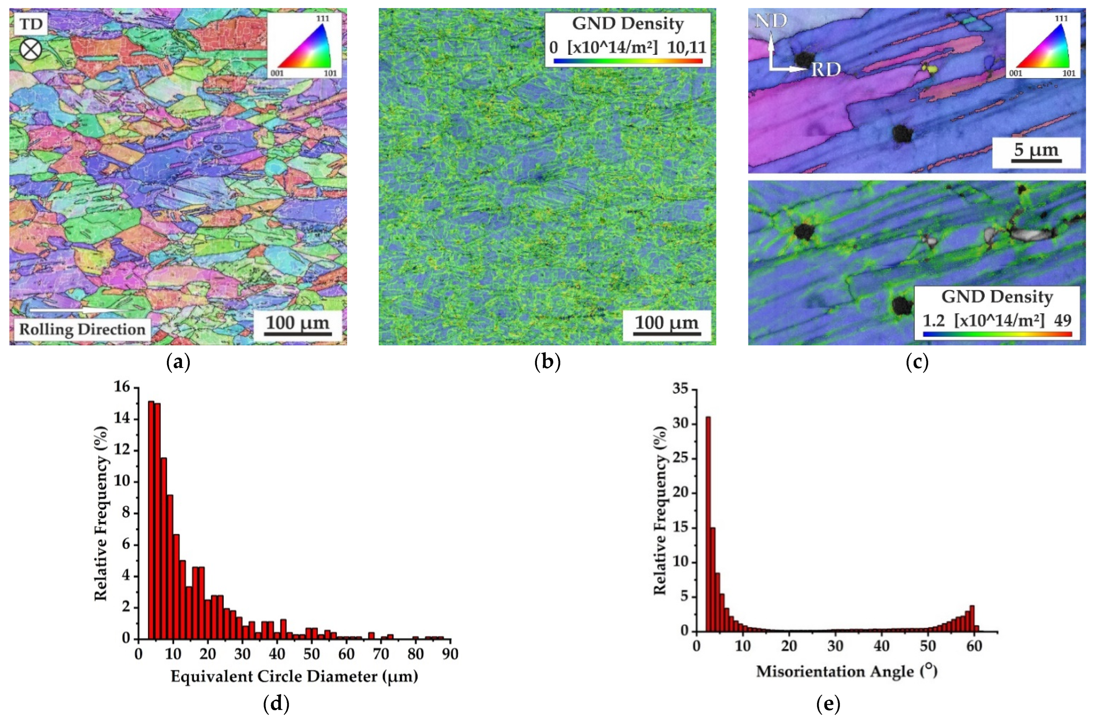
Figure 4.
SEM EBSD orientation map with HABs and LABs, denoted by black and white lines, respectively (a), geometrically nessesary dislocation (GND) map (b), magified orientation map and GND map (c), histograms of grain size (equivalent circle diameter) distribution (d) and grain misorientation distribution (e).
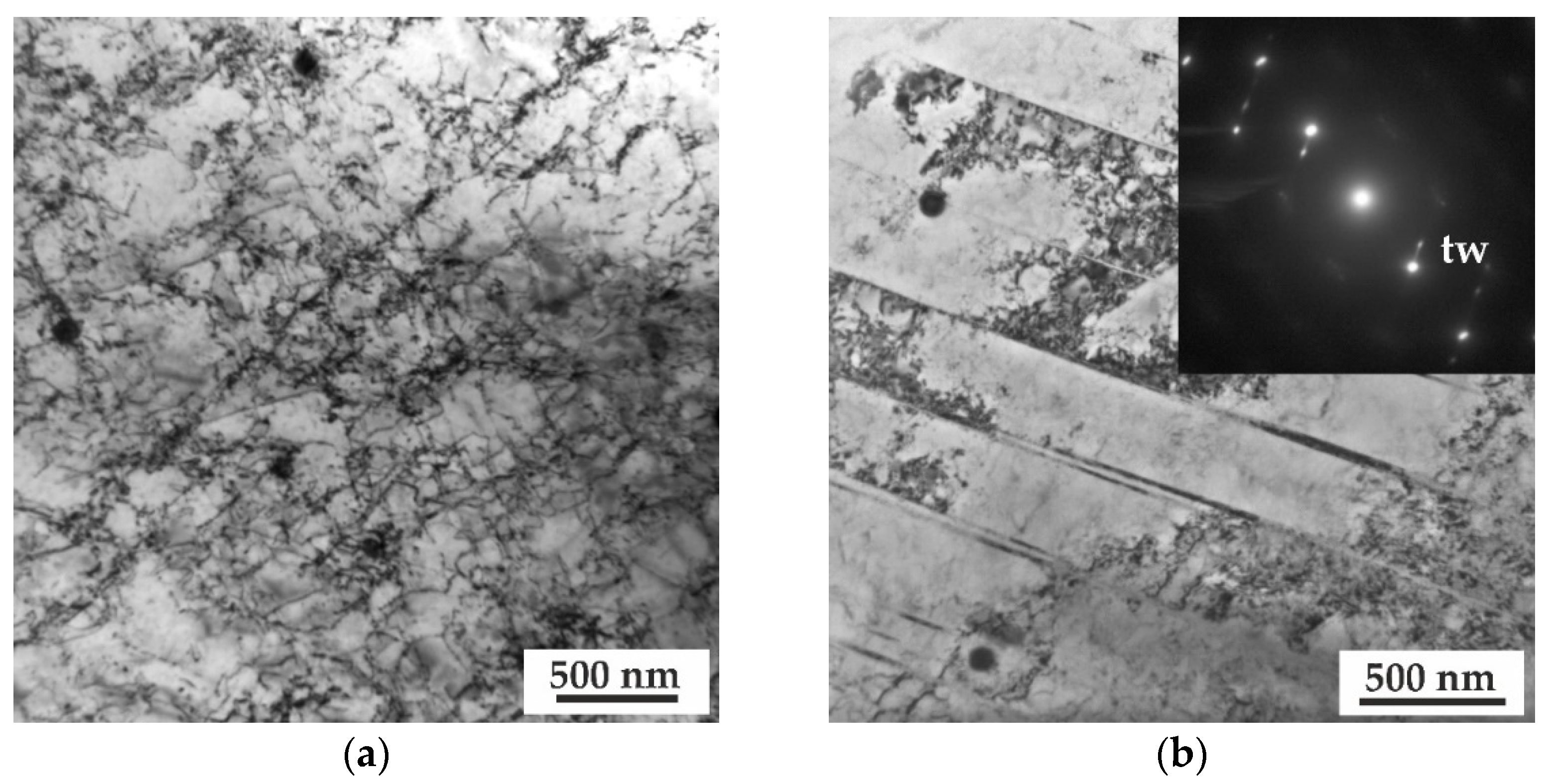
Figure 5.
TEM Bright Field (BF) images after ST. Dislocation substructure and dispersed particles (a), microtwins with corresponding selected area electron diffraction (SAED) pattern and dispersed particles, zone axis close to [110] matrix + [−1−10] twin (b).
Figure 6.
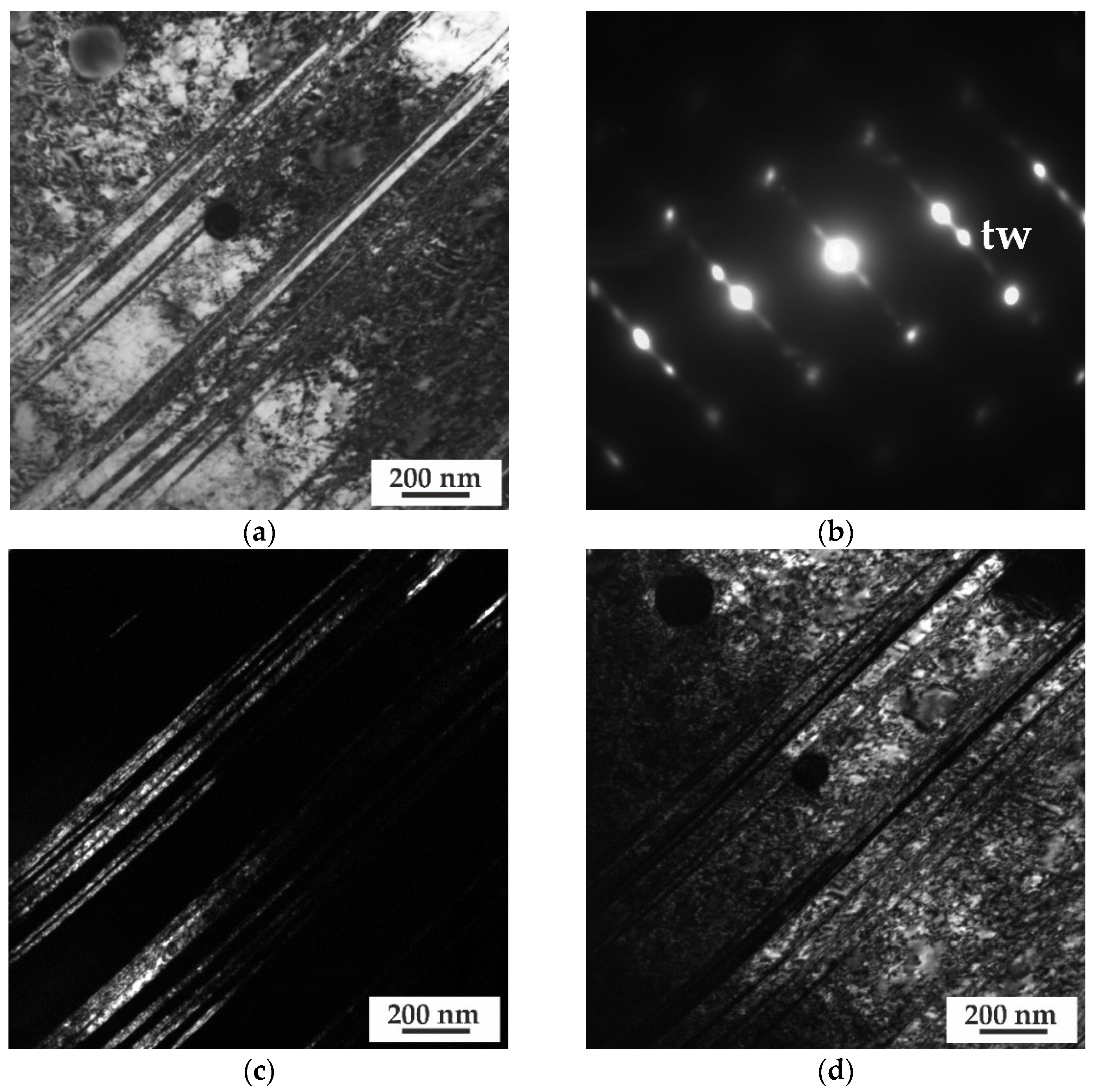
TEM images after CR. BF image (a), SAED pattern, zone axes close to [110] matrix + [−11−0] twins (b), Dark-field (DF) images in twin reflection (c) and matrix reflection (d).
Figure 7.
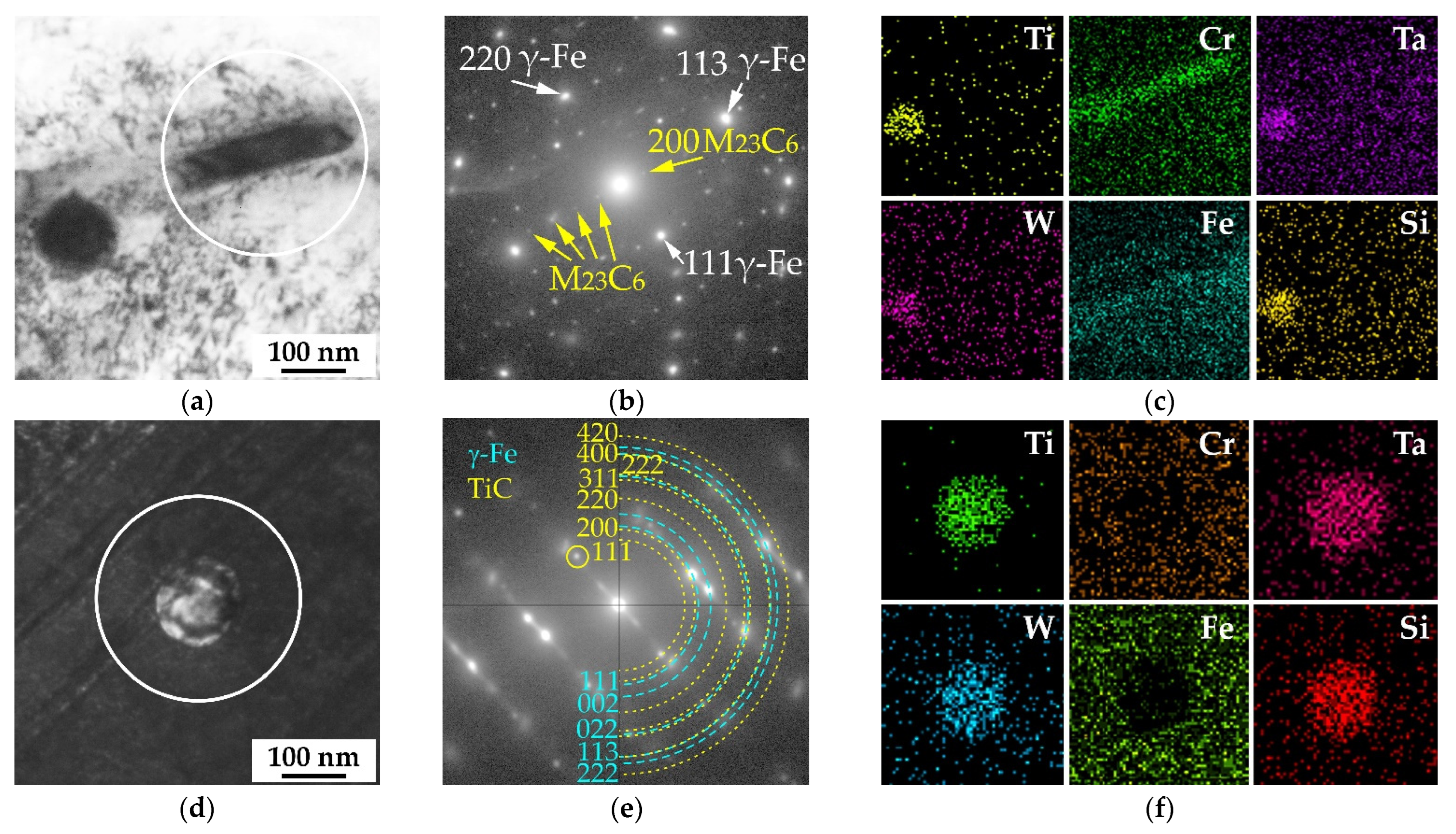
TEM BF and DF images of dispersed particles (a,d), corresponding SAED patterns from area marked by white circles (b,e), reflections of matrix and particles are denoted by white and yellow arrows, respectively, EDX elemental maps from particles (c,f): (a–c)—ST, (d–f)—CR.
Figure 8.
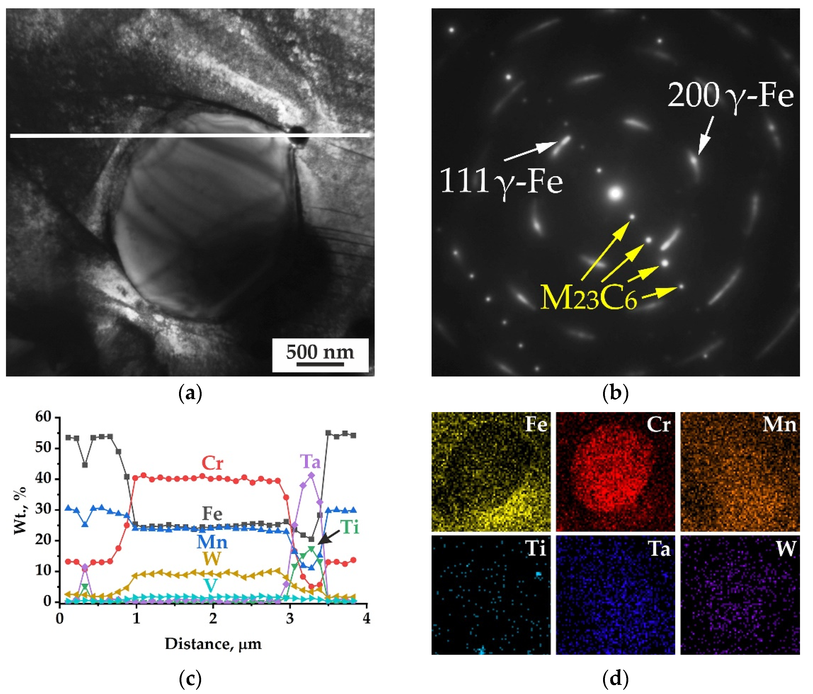
TEM images of coarse particle after CR. BF image (a), corresponding SAED pattern (b), reflections of matrix and particle are denoted by white and yellow arrows, respectively, EDX analysis along the line (c), elemental map from particle (d).
Figure 9.
Engineering stress–engineering strain curves of some samples of the steel after ST and CR at 20 and 650 °C.
Figure 10.
Fractographic images of the central part of tensile steel samples after ST (a,b) and CR (c,d), fractured at 20 °C (a,c) and 650 °C (b,d).
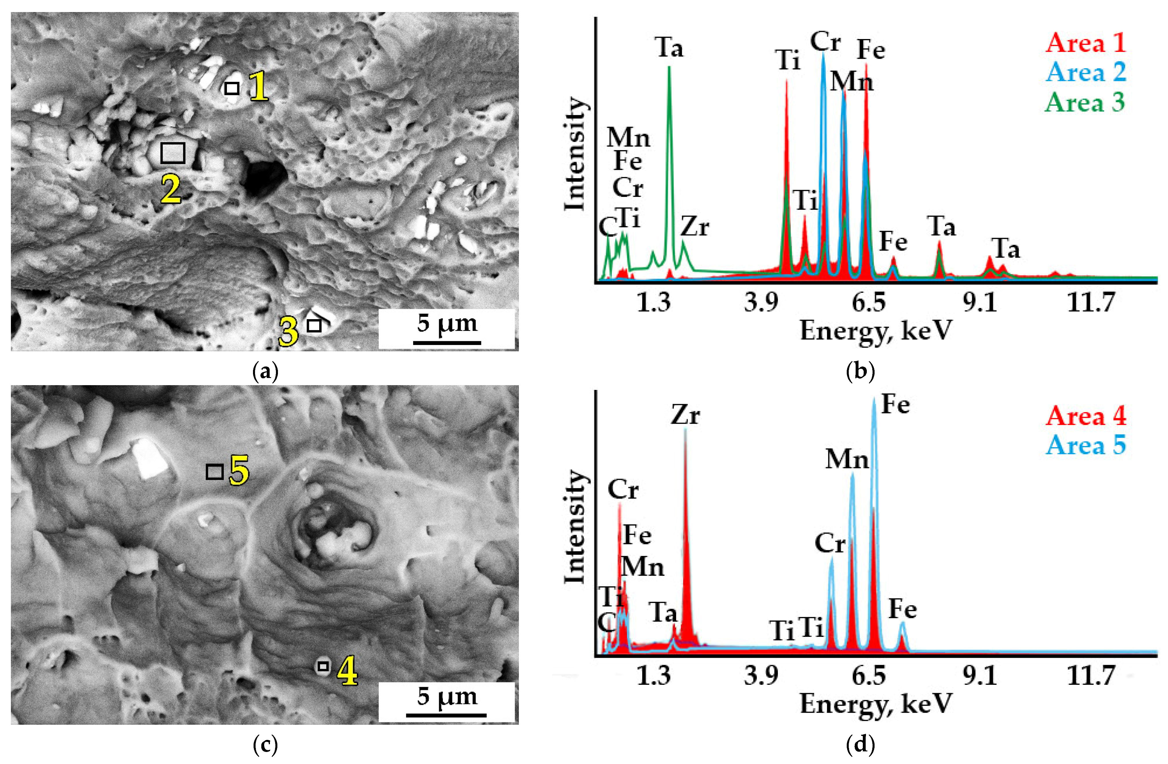
Figure 11.
Dimple fracture with second phase particles of the steel tensile samples, fractured at 20 °C (a) and 650 °C (c), and corresponding EDX spectra (b,d) from areas 1–5. Area 5 corresponds to the matrix phase.
Table 1.
Elemental composition of new high-manganese austenitic steel (wt. %, base Fe).
| Cr | Mn | Ni | Cu | W | V | Ti | Ta | Zr | Nb | Mo | Co | Si | S | P | C | B |
|---|
| 11.9 | 28.7 | 0.06 | 0.08 | 0.9 | 0.4 | 0.11 | 0.2 | 0.03 | 0.01 | <0.01 | 0.02 | 0.5 | 0.013 | <0.01 | 0.26 | 0.004 |
Table 2.
Mechanical Properties of Steels.
| Steel/Treatment | Tensile Tests Temperature, °C | Yield Strength, MPa | Tensile Strength, MPa | Elongation to Failure, % |
|---|
| Fe–29Mn–12Cr–W–Si–Ta–Ti–V–Zr–0.25C, ST | 20 | 331 | 662 | 75.5 |
| 650 | 95 | 353 | 42 |
| Fe–29Mn–12Cr–W–Si–Ta–Ti–V–Zr–0.25C, CR | 20 | 750 | 894 | 35.7 |
| 650 | 389 | 495 | 14.3 |
| Fe-16Cr-19Ni-2Mo-2Mn-Nb-Ti-B, ST [23] | 20 | 201 | 539 | 47.4 |
| 650 | 95 | 360 | 31 |
| Fe–20Mn–12Cr–W–0.25C ST [12] | 20 | 249 | 687 | 50.2 |
| 600 | 115 | 318 | 38.9 |
| Fe–20Mn–12Cr–Ti–W–V–P–B, ST [7] | 20 | 304 | 915 | 54.9 |
| 600 | 100 | 400 | 39 |
| Fe–20Mn–12Cr–Ti–W–V–P–B, CR [7] | 20 | 915 | 1114 | 11.3 |
| 600 | 500 | 620 | 8 |
| Publisher’s Note: MDPI stays neutral with regard to jurisdictional claims in published maps and institutional affiliations. |
© 2022 by the authors. Licensee MDPI, Basel, Switzerland. This article is an open access article distributed under the terms and conditions of the Creative Commons Attribution (CC BY) license (https://creativecommons.org/licenses/by/4.0/).
