Review

The Effect of Friction Stir Welding Parameters on the Weldability of Aluminum Alloys with Similar and Dissimilar Metals: Review

by
Wazir Hassan Khalafe
1,*,
Ewe Lay Sheng
1,
Mohd Rashdan Bin Isa
1,
Abdoulhadi Borhana Omran
2 and
Shazarel Bin Shamsudin
3
1
Department of Mechanical Engineering, Universiti Tenaga Nasional, Kajang 43000, Malaysia
2
Department of Mechanical and Mechatronic Engineering, Faculty of Engineering, Sohar University, Sohar 311, Oman
3
Department of Manufacturing Engineering, Universiti Tun Hussein Onn Malaysia, Parit Raja 86400, Malaysia
*
Author to whom correspondence should be addressed.
Metals 2022, 12(12), 2099; https://doi.org/10.3390/met12122099
Submission received: 26 October 2022 / Revised: 17 November 2022 / Accepted: 23 November 2022 / Published: 7 December 2022

Abstract

:
The solid-state welding method known as friction stir welding (FSW) bonds two metallic work parts, whether the same or different, by plastically deforming the base metal. The frictional resistance between both metallic workpieces causes them to produce heat, which produces plastic deformation and welds them. However, the weldability and strength of FSW joints mainly depend on the FSW parameters. This review work highlights the previous research work on the FSW parameters and their effects on the weldability and quality of the aluminum alloys joined with similar and dissimilar metals through the FSW method. About 150 research studies were systematically reviewed, and the articles included data from peer-reviewed journals. It has been concluded that the key parameters, including welding speed, “rotational speed”, “plunge depth”, “spindle torque”, “shoulder design”, “base material”, “pin profile” and “tool type”, significantly affect the weldability of the aluminum joint through the FSW method. Also, the selection of these parameters is important and fundamental as they directly affect the joint. It is recommended that future work focuses on FSW for aluminum. Among these, the most essential is the application of artificial intelligence (AI) techniques to select the optimum FSW parameters for aluminum welding.

1. Introduction

Welding is the method of joining two similar or dissimilar metallic parts by means of heating or pressure. The general kinds of welding are resistance welding, fusion welding, soldering/brazing, and solid-state welding (SSW). It is vital to note that SSW is a welding method in which two workpieces are bonded under pressure, through close contact, and most critically, at a temperature lower than the melting point of the parent materials. The intimate contact between both workpieces causes mechanical friction, which in turn produces heat and softens the parent material. This process is called fiction welding (FW). In the other form of FW, the mechanical stirrer is used to create mechanical friction and a heat zone to soften the parent metals for joining with each other. This process is called “friction stir welding” (FSW). The FSW was developed by Wayne Thomas at the Welding Institute UK in 1990 with financial support from the National Aeronautic Space Administration (NASA) [1,2,3,4]. Figure 1 illustrates the FSW of two workpieces of metal in the butt joint. The tool comprises a shoulder, a pin, and a specific measurement. The design and kind of metal for the tool selection are based on the metals to be welded [5].
The advantages of FSW are that the workpieces to be joined are not molten compared to traditional welding methods, such as electric arc welding, and thus avoid many defects in melting state welding. The preferred method for aluminum welding is FSW to obtain high mechanical properties of the weld joint. One of the advantages of FSW is that it is also economical and inexpensive, without the use of welding wires or filler material, protective gases, or heat generators, and is environmentally friendly [2,3]. Further, FSW possesses good advantages in the mechanical treatment of the surface, so welding is considered versatile [4,5,6].
There are many uses for the FSW, including welding of aluminum-magnesium alloys in the automotive industry (wheel rims, engine chassis, truck bodies, car frames, and fuel tankers), the aerospace industry (wings, fuselages, aviation fuel tanks, cryogenic tanks), the railway industry (container bodies, goods carts, carriages, and tramcars), the shipbuilding industry (marine and transport masts, sailing yachts, and offshore lodgings), and the shipbuilding industry (aerospace industry) [7,8,9,10,11].
The main parameters of friction stir welding are instrument rotation velocity, tool design, linear welding speed, and depth of pin. All of these parameters influence each other, and the optimum output in terms of better mechanical properties of the welded joint depends on the proper selection of these parameters [12,13,14,15]. Further, artificial intelligence (AI) techniques have also been used to increase the rate of production with better accuracy. The most common AI techniques, such as fuzzy logic [16], artificial neural fuzzy interfacing system (ANFIS) [17], heuristic methods [18], heuristic algorithms [19], wavelet [20], machine learning [19,21,22,23], hybrid systems [17], and artificial neural networks (ANN) [24]. The utilization of these AI techniques resulted in improved estimation of optimum parameters for better performance, perfect quality, and lower cost of the FSW process. Nonetheless, whether used manually, numerically, or through AI techniques, these parameters have a direct impact on the FSW process’s output. Therefore, this review work reviews the effect of these parameters on the weldability of the FSW process, which is the main objective of this review work. The information on FSW for identical and different metals has been incorporated to better understand the main objective and broaden the spectrum of this review work. For that purpose, the previous studies on FSW for similar and dissimilar parts have been reviewed, and the focus was also directed toward highlighting the impact of FSW parameters on the weldability of the welded joint. At the end of this review, a research gap has been extracted to further explore this research area.

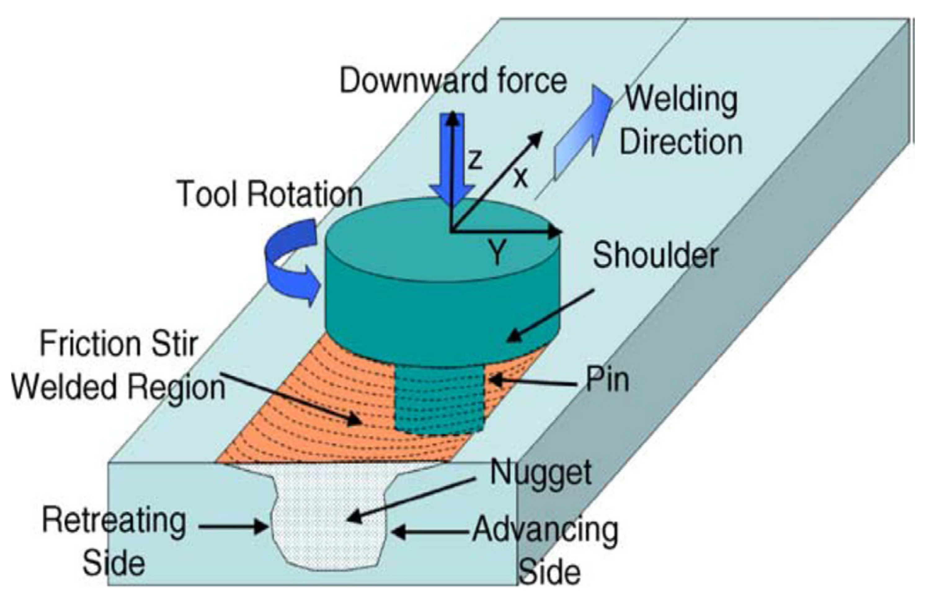
2. FSW Machine Tool Parameters and Selection Criteria

The FSW machine tool is very important for the selection of FSW parameters. The RPM and tool feed majorly control the heat generation during the process. During FSW, the temperature developed should be around 70–80% of the melting point of the material being joined. So, depending upon that, the feed and RPM should be selected. The tools are responsible for the material flow during the FSW procedure. The tool design depends upon the thickness of the material being welded [6]. Figure 2 the pins and shoulder of the tool cause easy fabrication of the FSW tool. However, in an extensive framework, the following criteria are of the utmost for FSW selection [25,26,27]:
i
Type of material to be welded by friction stir welding in line with the standard.
ii
Thickness of material.
iii
Friction stirs the welding position.
iv
Friction stirs welding quantity requirements.
v
Use the welded part.
vi
Mechanical properties are required for joint friction stir welding.
Figure 2. (a) Tool shape and (b) tool size parameters [28]. (Ref. [28] (has permission from Elsevier)).
Metals 12 02099 g002

2.1. Geometry and Design of Tool

The tool is a non-consumable material in FSW. The pin and the shoulder of it are the two main components for its design and selection, as displayed in s. However, the fabrication of it must be cost-effective and economical. The tool must possess high hardness, corrosion resistance, and better mechanical properties than the metal (s) to be joined through FSW [11]. Furthermore, the tool must be stable in dimension, resistant to creep, thermal fatigue, and fracture, and stable for chemical and thermal changes caused by contact with the metal (s) to be joined via FSW [6,29,30].
The design of the tool plays a key function in the FSW process, as the measurements of the pin and shoulder have an effect on the composition of the weld. The diameter of the pin helps in generating heat and welding the workpieces with each other, while its length is subject to the thickness of the workpieces [30]. Further, the surface of the pin generates sufficient heat to process the plastic deformation and movement of the plastic material. Collectively, the diameter and surface of the pin and shoulder also generate heat to form the plastic flow and join materials and entrap them [31]. However, the type of material for the tool significantly affects the plastic deformation of the metals to be joined. The common types of materials for FSW tools are carbide and hard steel, and they are used for the processing of light weight alloys such as aluminum, magnesium, and copper matrix [5]. In addition, refractory alloy, high-speed tool steel, H13 tool steel, and nickel-cobalt alloy MP159 are other materials for FSW tools that are frequently utilized. Tool materials are occasionally coated and heated to improve their characteristics [32]. The material of the tool ought to be such that the geometry and characteristics are maintained throughout the process. For workpiece materials that melt more easily, tooling material is essential [33]. As a result, the kind of workpiece to be welded and its thickness affect the choice of tool material with the requisite firmness.

2.1.1. Shoulder Shapes

The purpose of tool shoulders is to frictionally heat the workpiece’s surface areas, to provide the plunging forming action required for welding bond, and to confine the heated metal under the base shoulder surface [28]. Figure 3 shows shoulder shapes and surface features. Types of ideal shoulder ends are very flat and smooth; with contours; edges; scrolls; grooves; pits; and concentric circles. As shown in Figure 3, there are generally three different shoulder end surfaces. The flat shoulder end surface is the most direct form of them. Figure 3 summarizes common shoulder external surfaces, bottom-end surfaces, and end characteristics. The shoulder’s external surface is typically cylindrical, though rarely a conical surface is also employed. Since the shoulder thrust depth (1–5% of the standard thickness) is usually minimal. It is mostly anticipated that the shoulder’s external surface shape (cylindrical or conical) has little to no impact on the welding process [7,34].

2.1.2. Probe Shapes

Frictional heating and deformation are also possible outcomes of the stirring probe. It is intended to shear the material in front of the tool, shift the material behind the tool, and displace the contacting surfaces of the workpiece. The probe primarily determines the depth of deformation and tool travel speed. The shapes and primary characteristics of the probes are summarized in Figure 3. The probe has a flat or a domed end form. Presently, the most widely utilized variety of probes is one with a flat bottom that prioritizes ease of fabrication [28].

2.1.3. Tool Tilt

The tool has a tilt of 2–4°, so that the front part of the tool is larger than the back part, and the depth of the plunge must be adjusted until the weld is completed [34]. The tilting of the tool gives the quality of the weld joint. Therefore, the appropriate tilt is in the range of 2–4°. The tilt of the tool plays a major role in increasing the temperature of the welding area and applying pressure correctly from the lower shoulder of the tool to the materials to be joined, as well as assisting in the forward flow of the plastic material [11]. However, the increase or decrease in the angle causes a variation in the mechanical properties of the welded joint of the work specimens. The increase in the angle of inclination produced an improvement in the stiffness of the weld joint, and the temperature rise in the stirring area is caused by the increase in the angle of inclination [33].

2.2. Tool Rotational Speed (N)

Tool rotational speed is the crucial parameter of FSW, and it is measured by the number of revolutions per minute or second (rpm or rps) of the tool pin. The increase in rpm of the tool causes increased frictional temperature and welds the workpieces [12,35]. However, the quality of the welds mainly depends on the tool pin, the angle of the axis of rotation or the tilt of the tool, and the depth of inserting the pin into the metal (depending on the type of metal) [29,36]. Nonetheless, tool rotational speed is a significant parameter of the FSW process, and its increase or decrease directly affects the weld joint quality. However, it may vary from 400–1400 rpm but mainly depends upon the type of material of the workpieces [37].

2.3. Tool Linear Speed (v)

The tool linear speed v (mm/s) is another significant parameter of the FSW process and directly affects the weld joint quality. It can be measured in mm/min or mm/s. Further, the tool linear and rotational speeds are considered substantial parameters and significantly influence the material flow and heat input to form an FSW joint. In general, the heat consumption is inversely proportionate to the linear speed and directly relative to the rotational speed, yet there is interaction between the two speeds. Hence, both process factors must be correctly handled in order to create a quality weld and a greater ultimate tensile strength (UTS) [11].
With the right combination of welding speed (between 30 and 60 mm/min) and rotational speed (between 600 and 800 rpm), the weld strength was increased. Weld quality was observed to be lower when rotation and traverse speeds were increased [38]. Two tool speeds, such as how rapidly the tool rotates and how rapidly it runs along the interface, need to be taken into account for FSW. In order to provide a successful and efficient welding process, these two factors must be properly chosen. Although the link between rotational speed, welding speed, and heat input during welding is complicated, it is generally true that optimal welding would result from either increasing rotational speed or reducing traverse speed [34].

2.4. Tool Indentation Time

The time of indentation of the tool is the time between when the tool is stationary at the workpiece and when it begins to move along the joint. Such times of indentation normally range from 5 to 30 s. During this period, the heat generated spreads in the tool nib vicinity, softening the adjacent material and stabilizing material flow around it.
The other major parameters of the FSW process are: (a) rotational speed (rpm), (b) welding speed (mm/s), (c) axial force (kN), (d) tool geometry, (i) pin length (mm), (ii) tool shoulder diameter D (mm), (iii) pin diameter d (mm), (iv) tool tilt angle, and (v) D/d ratio of the tool [37].

3. FSW Joint Design

Numerous joint designs are commonly used in the FSW process. Figure 4 shows these joint designs. A backing plate is usually used to avoid any separation of both plates (workpieces). However, the thickness of both plates must be the same. Also, fixation becomes extremely important during the first “tool dive” course, as it tests the higher amount of force exerted on it. In the case of the lap joint, two “backing plate” plates in the coil setup are welded to each other by putting plunge FSW perpendicularly into the bottom plate via the top plate and going through it along the direction of the weld [12,29]. Additionally, the tool shape and welding parameters have a considerable influence on the material deformation and material flow in FSW to get a successful weld joint. The tool shape and welding parameters, as well as joint design, heavily influence the material flow. Thus, it is critical to effectively study and research the material flow in order to obtain optimal tool geometry and welds that are free of defects [31].

4. Literature Review

4.1. FSW of Aluminum Alloys with Similar Metals

4.1.1. FSW of Aluminum Alloys AA6061-6T with AA5083

Ref. [39] used two different aluminum alloys, AA6061-T6, and AA5083-H111, and did experiments for plate dimensions (150 mm × 150 mm × 6 mm) for the FSW method. Five distinct forms of pin profiles have been utilized to understand the behavior of the FSW method for joining both aluminum alloy plates. The Design of Experiment (DOE) was prepared to predict the experimental results and optimum parameters for the FSW method. The predicted results for the appropriate DOE of the optimal parameters found good welds and are in accordance with different alloys (AA6061-T6) and (AA5083-H111). The parameters listed in Table 1 create a free welding in connection to macro defects. These parameters have a substantial impact on the joint. Further, tensile specimen tests (48 specimens) depicted a good joint as most specimens were sliced into three parts for movement speed [39].
The predicted values agreed well with the experimental values, and the greatest tensile strength of 191 MPa was gained for a 1000 rpm cylinder threaded rotational speed and a welding speed of 60 mm/min. The optimum parameters were achieved through Gray Relational Analysis (GRA) and the Response Surface Methodology (RSM) matrix design [39].
The FSW process parameters (tool rotational velocity and feed frequency) were optimized by Lombard et al. (2008) by factoring in frictional power input. Due to its impact on malleable flow means in the thermo-mechanically affected zone (TMAZ) of the weld, friction force regulates the tensile strength and fatigue vitality of 5083-H321 aluminum alloy. It has been shown that rotational speed controls the rate of flaws in 5083-H321 aluminum alloy and that frictional power input, tensile strength, and low cycle fatigue life are strongly correlated [40].
Feofanov et al. [41] studied the structure formation in the weld seam during FSW and the relationship between the welding parameters and the quality of the joint for 1565ch Al–Mg alloy (without heat treatment). The tool advance per turn parameter was considered as an input parameter to compare the welding conditions for different aluminum alloys and for plates of the same alloy at different thicknesses (5 and 8 mm).
Butt-welded samples of sheets were produced in industrial trials with appropriate tools and equipment. All the welds were made by tools that formed a seam with a width of 16 mm for 5 mm thick plates and 20 mm for 8 mm thick plates. The experimental results showed that the FSW of a 5-mm sheet with tool advanced in the range of 0.53–0.66 mm/turn, with gaps extending to the face of the seam, as shown in Figure 5. These defects may be attributed to factors such as the tool’s small shoulder diameter, its large tip diameter, the considerable depth of the shoulder at the working (end) surface, insufficient insertion of the shoulder in the welded metal, insufficient pressure of the tool on the weld surfaces, low tool speed, considerable welding speed, and a large gap in the butt joint. Further, the results showed that welding with a tool that rotated at high speeds but moved slowly along the seam (small tool advance per turn) produced embrittlement of the material and the appearance of many defects, with a corresponding loss of weld strength.
Generally, weld defects appear in two stages. In some cases, the initial stage corresponds to the appearance of the primary crack at the root of the seam along the junction line. The next stage is a fracture in the direction of the maximum tensile stress [41,42,43].
In order to assess welding loads for tool pins with varying proportions of the flat feature for the FSW method, Su et al. [44] employed a three-dimensional computational fluid dynamics (CFD) model to explore temperature effect, material flow performance, and welding loads. The results of the heat phase, macrostructure, tool torsion, and span force for tool pins with and without flat features were compared in order to assess the viability of the CFD model. By locating various torque components on flat areas, an approach for the optimum design of tool pin profiles with three flats was provided. Additionally, the recommended methodology was used in accordance with the findings of the tool wear tendency and material flow behavior. Nevertheless, the suggested approach was applied to optimize the tool pin shape for a variety of processes.
Figure 6 shows computed torque modules on the pin flat for different welding parameters (in rpm and v in mm/min); (a) 400/80, (b) 800/80, and (c) 800/160. The findings support the hypothesis that an increase in the fraction of flat features on the pin side causes a continual rise in the rate of heat generation, temperature dissemination, maximum material flow speed, and total volume of the plastic volume zone. Also discovered is that the impact of the tool pin shape on tool force is less than 4.7%. When the flat proportion is high, the travel over force on the pin is decreased in an incredible and interesting way. Yet when the flat proportion is low, the influence on travel over force can be conceived of as being very, very little.
The experiment based FSW approaches gave a quick and in-depth understanding of how tool pin profiles affected the weld joint. The end pin’s thinness and threads encouraged more material flow and reduced weld flaws [45,46]. Additionally, compared to a straight tube-like pin, the end tube-like pin (with a modest thickness) with three surfaces altered the material flow caused by the shoulder and produced a more varied version of the material speed [47]. In contrast, Elangovan et al. [48] discovered that a tool pin with levels generated flaw-free welding and helped boost the mechanical characteristics in a satisfactory way when compared to tube-like and threaded pins. Square and triple nails were shown to result from measuring the crossing forces of various pin profiles [49,50]. The data measured by various experimental outcomes and the authors’ findings in Lombard et al. [40] were highly correlated. The findings showed that varied tool rotation speeds and types of workpiece metals result in different optimal tool designs. In their investigation, Dehghani et al. [51] found that a threaded pin helped the plasticized region travel downward by reducing the layer thickness of the interlayer metal compounds (IMCs) at the Al/Fe interface. According to Ramachandran et al. [52], tapered angles of 20° or 30° produced less smooth interfaces, while tapered angles of 10° produced joints that were more effective. Mehta et al. [53] used 9 different tools for dissimilar Al/Cu junctions were examined. The results showed that polygonal tool pin clamps caused fragmentation flaws and inflexible, brittle IMCs in the stirring zone, but the cylindrical screw form produced the highest joint strength.
Sathyabama [54] reviewed ample work for FSW and found that the design of the tool is very important for the FSW process. Furthermore, the main contributing FSW parameters, for instance, tool turning and linear speed, target depth, and spindle bend angle, were concluded based on the reviewed literature. The concave shoulder and cylindrical thread pin provided a defect-free FSW joint. Whereas temperature affects the FSW joint, and a rise of 400–500 °C due to flexible deformation and temperature increase causes a substantial microstructural change in the weld.

4.1.2. FSW of Aluminum Alloys AA6061 with AA5052 (T-Joint)

Mohan and Gopi (2017) studied the FSW process for AA5052 and AA6061 aluminum alloys. The AA5052 has been cut into the needed size (200 mm × 100 mm × 4 mm), and the stinger metal has a 10 mm thickness, whereas the AA6061 has been cut into the needed size (200 mm × 60 mm × 10 mm) by power hacksaw cutting and formed a T-joint as shown in Figure 7 [38].
Tools constructed of high-carbon steel that are not replaceable have been used to fabricate joints. The dimensions of the tool are schematically shown in Figure 8 and Figure 9, with the shoulder diameter (D) being 25 mm, the tool pin diameter (d) being 8 mm, and the tool pin length (L) being 7 mm. The joints were built using a single pin profile (hexagonal) and a shoulder profile. All the experimental results of the joints fabricated through the design of experiments (DOE) are shown in Table 2.
Power hacksaws were used to cut the welded joints into the desired shapes for the tensile specimens. The specimens were obtained in the weld’s typical direction. Tensile specimens deform after being loaded with the specimens. The T-joint tensile test was carried out by employing a handmade setup (Figure 10).

4.1.3. Friction Stirs Lap Welding (FSLW) of Aluminum Alloy (AA1100 with AA6061)

Aluminum alloys (AA1100 to AA6061-T6) sheets with a width of 3 mm were utilized for the FSLW joints, and welding parameters including tool rotational speeds (1000, 1250, and 1600 rpm), welding speeds (35, 75, and 100 mm/min), and pin lengths of 2.8, 5.4, and 5.7 mm with a cylindrical threaded tool pin shape were different. To assess the weld characteristic and joint effectiveness based on the aforementioned welding settings, X-ray radiography and tensile shear tests were performed. The most effective welding parameters were used for microhardness and microstructure measurements. The highest tensile sheer force of 4.93 kN and joint efficiency of 93 percent was achieved with a welding speed of 75 mm/min, a tool rotational speed of 1250 rpm, and a pin length of 2.8 mm. The new technique, friction stir diffusion welding (FSDW), was utilized at the above-optimized parameters to fabricate the lap joint. Vickers hardness was discovered to be at its ultimate estimate in the stir zone and to decline toward base metals for joints that were identical and dissimilar. As a result of their numerous functions in areas including chemical equipment, fan blades, sheet metalwork physical applications and welded fabrications, conduit, and naval applications, respectively, two aluminum alloys, AA1100 and AA6061-T6, were chosen to be combined by the FSLW process [55].
A tensile shear test was performed on AA1100 and AA6061 to determine the maximum sheer force of the welded joints at all welding parameters for identical and dissimilar welded joints. Figure 11 depicts the measurements of the tensile shear sample with two shims before the test. The outcomes of the tensile shear test conducted on each FSLW joint using a WDW-200E type general testing machine are shown in Table 3 [55].

4.1.4. FSW of Aluminum Alloys AA6082-T6 with AA6082-T6

Aluminum alloy AA-6082-T6A was welded using both FSW and traditional metal inert gas welding (MIG). Investigations were conducted into the welded joints’ mechanical characteristics. Tensile, metallographic, and hardness tests were used to determine how well FSW and MIG welded joints performed. The degree of distortion present in the joints produced by the FSW and MIG welding techniques was also evaluated. In order to comprehend the benefits and drawbacks of the processes for welding usages of the investigated Al alloy, FSW and MIG techniques were also contrasted. FSW welded joints produced better tensile strength. The heat-impacted area of FSW joints had a slimmer width than MIG welded joints. The findings in Table 4 demonstrate that FSW enhances the mechanical characteristics of welded joints [56].

4.1.5. FSW of Aluminum Alloys AA2219 with AA5083

The FSW method was used by Koilraj et al. [57] to combine the two different Al alloys, AA2219 and AA5083. The best parameters for the FSW process were found using the Taguchi approach. For the rotational speed, transverse speed, and D/d ratio, the ideal values were 700 rpm, 15 mm/min, and 3 correspondingly. However, the D/d ratio was important and made up 60% of the total contribution. Of the tool profiles examined, it was determined that the tubular threaded pin tool profile was the most effective. Additionally, based on the findings, it was established that FSW could successfully make butt welds for the sheets AA2219-T87 and AA5083-H321 with a combined efficacy of almost 90% (alloy AA5083).
Dilip et al. [58] joined two similar alloys, AA2219 and AA5083, through the FSW method. The results revealed that the significant joining of the two similar alloys did not seem to be a necessary condition for producing a good FSW joint. Alternatively, there was minimal mixing of the two basic materials visible in the welds. The material positioned on the forward side leads the nugget area in the FSW of different aluminum alloys. Higher joint efficiency can be attained by retaining the robust of the two bottom materials on the developing side.

4.1.6. Friction Stir Lap Welding of Aluminum Alloys AA2198 with AA7075

Astarita et al. [59] utilized sheets of AA2198 T351 (3.2 × 100 × 200 mm3) Al alloy and AA7075 T6 (2 × 100 × 200 mm3) alloy. Placing the AA2198 on top and the AA7075 on the base of the overlap arrangement with a 25 mm overlap length, welding activities were carried out. Welding speeds of 60 mm/min and revolutionary pitch rot/mm (20, 25, 30) were used in the experimental campaign which was conducted. Then, rotational speed rpm (1200, 1500, 1800) with mm/min (120) and revolutionary pitch rot/mm were used (10, 12.5, 15). Conclusions can be drawn; for all welds generated at a velocity of 120 mm/min, internal and external flaws (mostly grooves and tunnels) were discovered. The tool was rotated for the specimen processed at a velocity of 1800 rpm. Lower values were related to the heat-affected zone, but the micro-resistance values recorded in the nugget region were marginally greater than those of the BM. According to the overall pattern, hardness rises as heat input decreases, which is congruent with what normally occurs in FSW. The force trend changes throughout the plunging, residing, and traveling phases, displaying many peaks. Forces augment when heat input is reduced, i.e., when they rise with higher welding speeds and fall with lower tool spinning speeds. The detailed values for the Fz were consistently greater than those for the Fx. The strength of the joints is adversely affected by the hook, resulting in a de facto favored path for the crack spread.

4.1.7. Friction Stir Lap Welding of Aluminum Alloys (AA5052-O) with Al-(AA2024-T4)

According to Rafiei et al. [60], these sheets were divided into little samples that had cross-sections measuring 200 mm2 × 70 mm2. According to various tests, the AA2024 alloy needed to be on top of the AA5052 alloy and in touch with the shoulder of the FSW tool. The FSW tool was produced from hot-worked high-strength H13 steel, which has a resistance of about 45 HRC. The key features of this FSW tool are its 15 mm shoulder width, 6 mm pin width, and 3 mm pin height with M5 threads. The FSW parameters of w = 1250 rpm and v = 160 mm/min (i.e., a w/v ratio of 7.8 rpm. min/mm) were used to achieve a flawless and flaw-free dissimilar joint between the alloys AA2024 and AA5052 with remarkable interfacial attachment. The processing parameters had a big impact on how micro-mechanical interlocks formed and looked at the interface of two alloys. The connecting mechanisms between these incompatible AA2024 and AA5052 alloys were sped up with the use of interlocks, which got finer and more numerous as w and v increased. The maximum w and v estimates with direct heat input estimates, i.e., w = 1250 rpm and v = 160 mm/min, produced the ideal conditions for dissimilar joining. Additionally, after using the FSW method at various parameter settings, the precipitate structure and morphology varied. These changes mostly affected the precipitation solidified AA2024 part of the junctions between dissimilar materials. The friction-stir welding procedure used in the (AA5052) and (AA2024) lap joint designs was evaluated. On the micro-configuration and mechanical characteristics of different FSWs, the implications of processing factors and joint layout were discussed. The peak temperature was constantly raised at all points along the developing area, receding rim, and middle line, reaching an upper limit value of roughly 550 °C with rising w and declining v (or boosting the w/v ratio). Variations in the thermal description, relying on the heat input parameter with regards to the w/v ratio through the FSW development, drastically altered the shapes of material inter-blending between these incompatible alloys. For the improved dissimilar FSW, the connection between microstructure and mechanical characteristics was expanded, with the fundamental process of reinforcement being described as particle structural enhancement consistent with the Zener-Hollomon parameter (Z). The joint’s design, which places the AA2024 alloy on the upper part and uses the processing settings w = 1250 rpm and v = 160 mm/min, results in the creation of a dissimilar joint with the best possible intermixing of dissimilar materials and, consequently, correct mechanical properties.

4.1.8. FSW of Aluminum Alloys AA2219 with AA2219

Arora et al. [61] cover how FSW was applied to the AA2219 material that the Indian Space Research Organization uses to produce cryogenic fuel tanks. The study’s two similar Al alloy 2219 plates, each gauging 250 mm by 50 mm by 5 mm, served as the work components. FSW was conducted using a modified vertical milling machine. The mean values of the variables while employing a face triangle end pin shape are tool rotations (RPM) 250–400, welding speed (60–180 mm/min), shoulder diameter (18–22 mm), and pin diameter (7–9 mm), according to the L9 orthogonal array. The force measurements that were taken throughout the welding stage of the runs of the process were meant to provide a sole value that was then applied for pooled ANOVA and the design of experimental models. The pooled primary impacts of welding activity parameters on Fx are below; the constructed empirical model for Fx and the reported ANOVA analysis for mean effects. Fx = 478.2(N)−468(S)0.466(D)0.0078(d)0.523. As welding velocity, pin span, and tool shoulder rise, so does Fx, which measures the resistance to the tool moving forwards through FSW. It is inversely related to the speed of the tool’s spin. As shown by the ANOVA study, welding speed is the most important process parameter impacting Fx. The model also shows the same, with welding speed having the largest coefficient. The primary impacts of process variables on Fz = 9.68(N)−0.312(S)0.46(D)2.78(d)−0.121, which is the pooled ANOVA analysis for the average effects model. From Fz, which is inversely related to the rotating velocity and the pin width but relative to the shoulder span and welding velocity, the shoulder diameter can be extrapolated to be the most important factor, followed by welding and mean rotational speed. The following formula can be used to determine the axial thrust that the tool shoulder produces: Fz = π (D)2 σ Y / 4 . This formula shows that axial thrust strongly depends on shoulder diameter. Fz increased by a factor of 75, with a 50 percent quantitative improvement in the tool shoulder region (average 20 mm). When compared to the values of the base material, the tensile characteristics of welded specimens degrade. The shoulder diameter, together with welding speed, has a major impact on the tensile strength of the welds. The most important factor affecting % extension is welding speed. The nugget’s microstructure was composed of recrystallized particles with a mean tenfold reduction in particle size. TMAZ underwent microstructural alterations because of the blended heat and deformation effects. Process forces (Fz and Fx) play a crucial role in choosing the best milling machine. Shoulder diameter and welding speed both have a small but significant impact on axial thrust, while tool rotating speed, pin diameter, and welding speed only have a minor impact on Fx.

4.1.9. FSW of Aluminum Alloys AA 2024 T3 with AA2024

Viscusi et al. [62] constructed the base and upper sheets of the lap joints using AA 2024 T3 sheets. The sheets have a 1.27 mm thickness. Regarding the welding process parameters, the rotational speed (RS) varied from 2222.to 5.950 rpm, and the inverted travel speed (TS1) varied from 0.533 to 0.155 s/mm. The depth of the plunge, tilt angle, and travel angle were all maintained at 0.01 mm, 0.11 mm, and 1 mm, respectively. One tool design was employed; the top and bottom widths are 5.06 mm and 2.77 mm, respectively, with a 2.03 mm length; the shoulder width is 12.04 mm with a 7° concavity. This work devised a strategy to improve the friction stir mechanical performance of welded joints. The product’s strength was selected as an important factor, and its reaction was improved using the reaction surface process. The best yield strength surface was produced by this technique, which included a crucial composite layout and the consequently steepest ascent algorithm. The outstanding performance of FSW technology was demonstrated by tensile testing on base metal specimens using benchmarking data from treated samples. The best welding results were discovered with these requirements: rpm of 1250 and TS1 of 0.241 s/mm. These results were estimated by selecting the minimal value between HAZ and nugget area ratio for both yield and maximum strength. Tensile test findings were validated by shear tests. An analysis of the hook’s defect led to an estimation of the nugget zone’s grain size.
Table 5 shows the ability of friction stir welding to weld aluminum alloys with different thicknesses and positions (Butt welding, Lap welding-joint welding). In this case, we find a difference in the design of the tool, as well as in the values of the friction stir welding parameters. The results in the mechanical properties of the friction stir welding line are different. It requires finding a rule in choosing the values of the variables that depend on the type, thickness, and position of the alloy to be welded to obtain high mechanical specifications.
In friction stir welding of similar aluminum alloys, three cases were taken. In the first case, it is welding (AA6082-T6 to AA6082-T6). It was a comparison between MIG and FSW welding FSW welded joints produced better tensile strength. The heat-impacted area of FSW joints had a slimmer width than MIG welded joints. As for the second case, the research discussed (FSW AA2219 to AA2219), was used for further analysis, namely pooled analysis of variance (ANOVA) and for developing empirical models. Axial thrust is affected significantly by shoulder diameter and slightly by both tool rotational and welding speeds, whereas Fx is affected strongly by welding speed and slightly by tool rotational speed and pin diameter. FSW of AA 2024 T3 to AA2024, in this research, a procedure to optimize the mechanical behavior of friction stir welded joints was an improvement. Yield strength was select as a factor of interest, and its response was optimized by using a response surface method. RPM 1250 and TS-1 0.241 s/mm were the best performances evaluated, choosing the minimum value between HAZ and nugget zone ratio for both yield and ultimate strength.

4.2. FSW of Aluminum Alloys with Dissimilar Metals

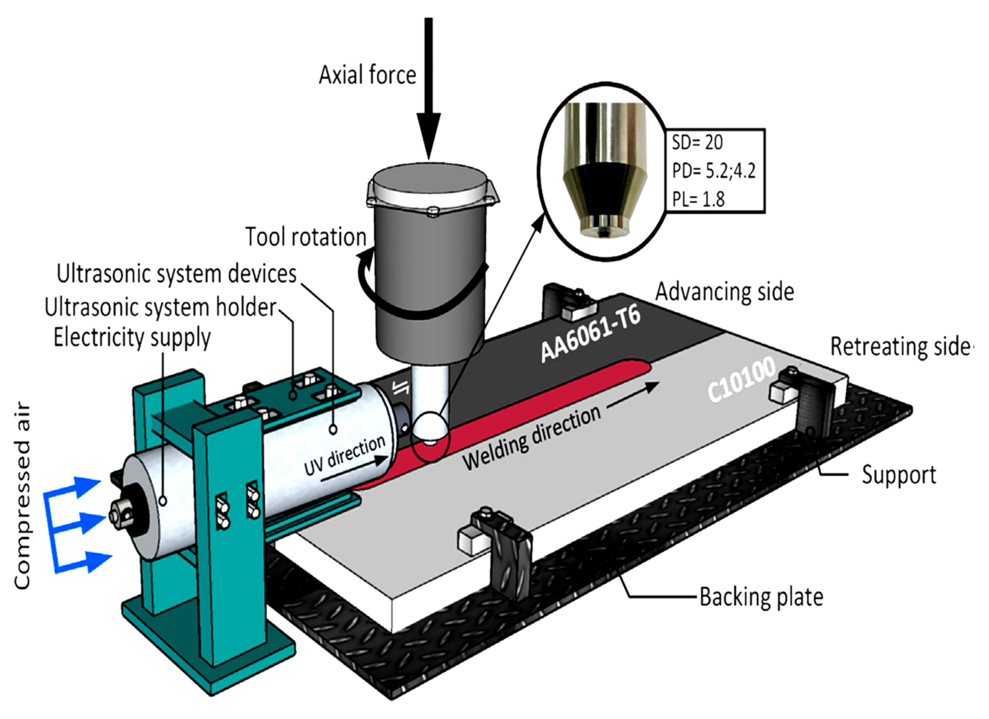
4.2.1. FSW of Aluminum Alloys with Copper

Karrar et al. [63] joined (Butt joint) two dissimilar AA5083 (3 mm thickness) and copper plates through the FSW technique. In order to explore the mechanical characteristics of the FSW joint, the two primary parameters of tool rotational velocity and tool traversing velocity were used. The greatest tensile strength of 203 MPa and joint efficacy of 94.8 percent were accomplished at 1400 rpm tool rotation and 120 mm/min traversing. Further, due to the different chemical compositions of two different metals, the FSW provided better weld efficiency and was considered an alternative to traditional welds. The traditional welding methods provided less efficient weld joints with some shortcomings, such as porosity, cracking freezing, oxidation, and low deformation [63,64,65,66,67,68]. In other research, Firouzdor et al. [69] joined (lap joint) aluminum with copper through the FSW method. An external cooling medium was utilized to monitor the temperature and decrease the development of compounds between the two metals to be welded. This external cooling medium also provided a homogeneous filler material between both materials (workpieces). The cold rolling process was carried out to improve the mechanical and electrical specifications of the FSW joint. The utilization of an external cooling medium resulted in the high quality of the FSW joint. Furthermore, it decreased the FSW process’ peak temperature. Less mineral composition was produced by the temperature drop, which also enhanced the strength of the lap joints. Nevertheless, the improved FSLW produced faulty junctions at greater tool traversal speeds. Figure 12 depicts the traditional and improved FSW processes.
Sharma et al. [70] published a review paper on the FSW of aluminum to copper. This review work systematically covered and summarized the different related topics such as “the effect of tool design and geometry”, “the FSW process parameters”, “FSW strategies on mechanical properties”, and “microstructure and formation of defects during dissimilar FSW of Al–Cu”. At the end of their review work, major findings were presented, and also future suggestions were made for dissimilar FSW of Al–Cu. In their findings, it was found that “the material flow pattern”, “tool geometry and design”, “welding tool wear”, and “microstructural stability” were essential features that needed more knowledge of joining Al–Cu utilizing FSW. Due to that, it was recommended that these parameters are necessary to investigate for understanding the FSW process for welding two dissimilar metals (Al–Cu).
Hou et al. [71] joined (butt joint) Al 6061 alloy with pure copper through FSW, and the mechanical properties of the joint were investigated by varying the tool offset value. The results found that the ultimate tensile strength increased by decreasing the tool offset and then decreased drastically when the offset was more than 1.6 mm. Further, the X-ray tomography results showed that an effective mechanical interlocking structure was formed with a chaotic interface along the joint line. In addition, in-situ tool temperature measurement showed that the stir zone peak temperature was highly dependent on tool offset. In the other research, Li et al. [72] used FSW (spot welding) to join aluminum with copper. In their results, it was found that FSW was considered the better method to join two dissimilar metals. The FSW (spot weld) provided better mechanical properties, an improved microstructure of the joint, and a defect-free joint for Al-Cu welding.
Discussing the different nature and chemical composition of the two different metals to be joined through FSW, Al alloy has a low melting point, ability to form, high plasticity, high specific strength, low density, lightweight structural material, and other positive features [72,73], whereas Cu has high thermal conductivity, excellent electrical conductivity, and good corrosion resistance [72,73,74]. Further, the application of both metals is found in numerous industrial products, especially in the electrical and refrigeration industries, which makes it important to understand and further explore the research work on FSW on these two metals [72,75,76].
Friction spot welding of Al alloys AA5083 with copper was employed by Shen et al. [77] RPS 100 friction spot welding was used to join deoxidized copper sheets of different sizes (2, 25, and 100). Two thousand revs per minute consist of a 2 mm drop and a 1 s brood. The alloy was positioned on the surface of the copper in order to limit heat response. A different Al/Cu different FSpW joint eutectic liquation has been studied. Both the detached MgCuAl2 eutectic structures are part of the primary eutectic fabrication. The AA5083 alloy structure also explains the trine eutectic melting as well as mass transport by atomic diffusion and substance flow at high temperatures under the state of extreme plastic deformation. The matrix A, which is depicted in Figure 13 as the prime a-Al, contains dominating Al and minor amounts of Mg and Cu. Coupled eutectic B’s dark stage is predominantly abundant in Al, whereas the brilliant stage mimics split eutectic C. Eutectic D is also Al-opulent but drained of Cu or Mg. Conversely, due to the size of the eutectic compositions, immediate quantitative EDS evaluation is inaccurate for identifying these stages. This is referred to as micro separation. The FSpW process’s requirement for non-stability freezing or fast cooling causes isolation. Cu is ejected from the oversaturated Al particle internal to the particle border when it cools. Nevertheless, the significantly lower temperature has prevented the complete distribution of Cu from occurring. As a result, a diffusive characteristic could be observed, such as the surge in Cu strength from the matrix base to the eutectic, as indicated by the two arrows in Figure 13. In conclusion, the Al/Cu weld’s eutectic compositions are mostly a-Al-S eutectic in both linked and detached fashions. The mass movement caused by atomic flow, substance flow, and malleable deformation can be seen as the cause of the melting in eutectic. Materials (Al base metal) are forced into the cylinder compartment held off by the fix through the entrance of the sleeve. Due to sleeve movement and fabric plastic deformation, a portion of Cu is removed and carried into the top area of the weld when the sleeve point moves towards the Al/Cu primary boundary. Diffusion into the encircling Al matrix devours these separated Cu pieces. The formation of a specific eutectic structure was then possible in particular isolated places. Inherent liquation will occur when the temperature moves toward the eutectic spot. Additionally, atomic diffusion expands and speeds up in a liquid state. The joint develops eutectic formations after a quick cooling. While this is happening, a few eutectic a-Al particles that are identical to the original grains develop into the matrix.
Muhammad [78] successfully joined C10100 pure Cu plates and AA6061-T6 Al alloy employing a new ultrasonic vibration-assisted friction stir welding (UVaFSW) technology were the effects of ultrasonic vibration on joint development, microstructural characteristics, microstructure, and technical qualities. The joint structure mechanism and robotic characteristics were found to be improved by the innovative UVaFSW technique. The joint strength increased up to 600 rev/min; however, as the heat input increased, the joint strength decreased. The system layers displayed more uniform characteristics; the reactive materials’ fabric flow performance was enhanced, and the joint interface intermingling was also improved. The Al-Cu joint’s fracture mechanism is altered by ultrasonic vibration, which causes the fracture to move to the Al side’s heat-affected zone and causes a malleable fracture to form on the surface. In contrast, the fracture in the joints that did not experience ultrasonic vibration mostly occurred in the Cu part of the joints’ thermo-mechanically impacted zone, and the fracture exterior displayed a mixed brittle-ductile fracture feature.
Al and Cu were welded together in [79] using FSW and friction stir welding with ultrasonic vibration assistance at various base material positions (Figure 14). The electrical conductions of the FSW and ultrasonic vibration supported FSW joints are found to be within acceptable limits. It was discovered that adding ultrasonic power to the welding process decreases the roughness of the weld surfaces, particularly in type 1 joints. (a) In type 1 and type 2 joints, the intermetallic compound layer width and the size of the distributed copper particles both decreased, increasing the strength of the Al/Cu connection (Figure 14). C10100 and an AA6061-T6 with measurements of 200 × 65 × 2 mm3 were FSW with and with no ultrasonic vibration, respectively. The electrical conductivity of the welds was not improved in any way. According to various writers, positioning copper at the RS makes it difficult to obtain a high-quality weld and structure in an Al/Cu FSW weld. Although it was discovered that ultrasonic vibration increased joint strengths, it had no effect on how well the welded joints conducted electricity in either of the two studied specimens. In contrast to the generally accepted similarity, the mechanical and electric features of the Al/Cu welded junction cannot be compared. One sign of success is that each electrical conductivity measurement falls within the range of the electrical conductivity of the basic materials. (b) The failure of the weld at the Cu/SZ border of type 2 joints and the SZ of type 1 joints indicates distinct fracture phases and processes in each kind of joint welded using H13 tool steel (Figure 14). This phenomenon is caused by the mixing procedures that the various types of joints have devised. Reduced IMCs tier thickness in type 1 joints and smaller particle sizes in type 2 joints both boosted the strength of the Al/Cu joint. Greater in type 2 joints than in type 1 joints, the supplement of ultrasonic vibration increased the Al/Cu joint strength. Additionally, type 1 had a significantly enhanced Al/Cu stir area strength. However, type 2 joints show negligible enhancement.
Sahu et al. [80] studied the FSW of 6061 Al alloy and industrially pure Cu to unite their different butts. The maximum malleable strength of the soldered joint amplified as the mean counterbalance decreased from 2 mm to 0 mm but decreased significantly when the counterbalance exceeded 1.6 mm. Outcomes from X-ray tomography revealed that a disorganized interface next to the joint line generated an efficient mechanical interwoven system. Furthermore, in-situ device temperature dimensions revealed that the device was counterbalanced, having a significant impact on the stir area maximum temperature. As basis materials for FSW in a butt joint construction with Cu on the improving part, plates of commercially pure copper (C11000) and Al alloy 6061-T6 were employed. This arrangement is seen in Figure 15a. The plates were cleaned, dried, and then cut into 150 mm × 50 mm pieces. These pieces were then securely clamped together before welding.
This study involved changing tool counterbalance and Al/Cu dissimilar FSW under ideal conditions. The impact of offset on maximum heat, mechanical characteristics, and microstructure was assessed. The inferences that can be made are as follows: (i) The tool counterbalance affects the surface quality of joins. When the tool is counterbalanced farther into the copper, it deteriorates. (ii) The development temperature was significantly impacted by the tool counterbalance. The elevated temperature grew as the counterbalance decreased. With a 0 mm tool counterbalance, the maximum peak heat was observed. (iii) A fracture close to the WNZ/TMAZ interface was caused by a large tool counterbalance of more than 1.6 mm, which led to a weak connection at the interface. Reducing the counterbalance caused the position of the fracture to shift within the WNZ and more void defects to develop. (iv) Using a counterbalance of 1.2 mm, the threshold UTS of 152 MPa was attained. (v) The intermingling of the materials was not uniform throughout the welding process, but an interconnecting formation was created, adding to the strength of the connection.
In Muhammad et al. [81], welding of AA6061-T6 and C10100 with comparable dimensions of 2 mm thick, 200 mm long, and 65 mm thick was done using the UVaFSW and FSW procedures, as shown in Figure 16’s explanation of the UVaFSW development standards. The frequency, amplitude, and power limits for the ultrasonic vibration system were 20 kHz, 25 mm, and 3 kW, respectively. The shoulder diving depth, traverse speed, tool slope angle, and tool spin velocity were all set to the same welding procedure factors of 60 mm/min, 700 rpm, 20, and 0.1 mm, respectively, for the soldering processes. In this work, dissimilar junctions between the AA6061-T6 and C10100 were created using the FSW and UVaFSW procedures, with three distinct tool counterbalance degrees from the Al edge to the Cu edge. It provided flaw-free joints with perfect strength in both joints created and with no ultrasonic vibration when the tool was counterbalanced toward the Al base material and in the Al/Cu boundary. However, both joints manufactured with and with no ultrasonic vibration had faulty characteristics such as wormholes and a dearth of surface load due to tool balancing towards the Cu base material. With the addition of ultrasonic vibration, the minimum Feret diameters and particle areas in joints made with tools counterbalanced towards the Al base material were reduced by 73.3 and 42.6 percent, respectively. In comparison to traditional FSW, ultrasonic vibration joints have a greater tensile strength.
It is well known that using a tool offset toward aluminum alloy is now required to obtain high-quality joint characteristics when combining materials that are different. In this work, the AA6061-T6 and C10100 were welded using the FSW and UVaFSW processes at various tool offset positions, including the Al edge (Case 1), the Al/Cu border (Case 2), and the Cu edge (Case 3). Comparative studies were done on how the tool offset procedures affected the mechanical characteristics, microstructure, and weld surface polish of the welded joints generated by these processes. The subsequent is a synopsis of the key outcomes: (1). When using the tool counterbalance process, selecting the best welding activity factor encourages the production of a high-quality solder surface even with the inclusion of ultrasonic vibration. (2). As an illustration, the addition of ultrasonic vibration caused the tier width in the Case 2 joint to decrease from 0.76 mm to 1.79 mm. An unusual change in the layer thickness’s growth behavior occurred between Case 1 joints, where the layer thickness was 2.63 mm and 1.89 mm for FSW and UVaFSW, respectively. (3). When ultrasonic vibration was introduced to the Case 1 joints, a significant shift in the dimensions and structures of the disseminated Cu particles was set up. Because of this, they were able to reduce the mean particle size and the lowest Feret diameter by 73.3 and 42.6%, respectively. In spite of this, Case 2 joints showed a percent decrease in the lowest Feret diameter and mean particle size. By clearly separating the two types of joints, it is possible to see how much the tool offset approach has affected the microstructure of FSW joints. Additionally, as opposed to the FSW joint, the joints formed using ultrasonic vibration have stronger joint strengths because they are responsive to changes in the dimensions of the dispersed Cu elements. (4). In particular, the Case 1 joint, which was sensitive to the outstanding joint operation, is affected by the occurrence of ultrasonic vibration, which causes the fracture situation to shift to the less varied region.
With the aid of a gantry FSW machine, Al/Cu were butt-welded [82]. Plates that are 5 mm thick, 300 mm long, and 70 mm wide of 1060 Al and 99.9% pure, galvanized copper are available. In order to properly FSW Al and copper plates, the tool had to be counterbalanced to the Al surface. This produced excellent metallurgical connections at the Al/Cu boundary and the development of a thin, constant, and homogeneous Al/Cu intermetallic compound tier. A complex configuration was also created in the nugget area by the production of many IMC particles. According to tensile testing, the Al/Cu boundary connecting strength was greater than 210 MPa, and the FSW joint crashed in the temperature-impacted region of the Al part. The following findings are drawn from the synopsis: (1). By counterbalancing the tool in the Al part, FSW of industrially pure Cu and 1060 Al alloy was accomplished. The PRZ that developed at the base of the nugget zone had a complex composition made up of different-sized particles scattered throughout the Al matrix. (2). Because of the Al-Cu IMC particles’ increased impact, the aggregate configuration’s UTS reached 210 MPa and its stability considerably increased. Al2Cu, Al4Cu9, and a few Al/Cu particles made up the majority of the strengthening particles. (3). At the Al-Cu contact, an outstanding metallurgical connection was created with a connecting strength greater than 210 MPa and 180 deflecting without breakage. This is because an IMC layer consisting of Al2Cu and Al4Cu9 sub-tiers is developed constantly and consistently with an appropriate width of about 1 m.
Xue et al. [83] employed 5 mm thick, 300 mm span, and 70 mm wide grip-welded FSW system, 1060 Al, and industrially pure Cu (99.9% purity) plates. The welding tool utilized in this investigation featured a shoulder that measured 20 mm in width and a pin that was 6 mm in width and 4.8 mm in length. It was composed of a heat-treated tool steel revolving pin that rotates 1000 to 400 revolutions per minute while moving at a steady 100 mm per minute. Multiple pin counterbalances ranging from 0 mm to 3 mm in diameter were utilized during the welding processes. The experimental findings showed that when the stiff Cu plate was attached to the developing part, sound defect-free joints could be formed even with greater pin counterbalances. Higher rotational velocities and appropriate pin counterbalances of 2.5 and 2 mm resulted in good tensile qualities; in addition, the joint generated at 600 rpm with a pin counterbalance of 2 mm might be bent 180° without breaking. The interface microstructure between the Al matrix and Cu bulk was directly connected to the mechanical characteristics of the FSW Al/Cu joints. Sound FSW Al-Cu joints required a thin, homogenous, and constant intermetallic composite tier at the Al/Cu butted contact. Weak mechanical characteristics were caused by the stacking layered formation that formed at the Al/Cu boundary under greater spin proportions. In this scenario, cracks start quickly. Different FSW base Al/Cu joints were created in this study using a variety of static positions and pin counterbalances, and the goal of this work is to clarify the relationship between the FSW characteristics and connection strength in joints between distinct alloys.
In conclusion, the effect of the stable spot, pin counterbalance, and rotation level on the fine structure and technical characteristics were examined during the FSW of industrially pure copper and the Al alloy 1060. The subsequent assumptions are drawn: (1). Only when the solid Cu plate was attached to the developing part could a solid, flaw-free junction be formed. When the ductile Al plate was mounted on the developing part, a significant volume defect was seen. This is explained by the fact that during FSW, it was challenging to carry the tough Cu mass material to the developing part. (2). In the bigger pin counterbalances below 2 mm to the Al matrix, sound defect-free connections were formed, and a satisfactory metallurgic connection between the Cu mass/pieces and the Al matrix was accomplished. Nevertheless, due to the hard mixing between the big Cu chunks and the Al matrix, faults occurred readily at smaller pin offsets. (3). As the rotation rate rose, the joint surface got worse. At the shorter rotation level of 400 rpm, many flaws developed in the nugget region, whereas at greater rotation levels, strong metallurgical bonding occurred. The Al/Cu bumped boundary was thin, consistent, and constant at lower rotational speeds of 400 and 600 rpm; conversely, at higher rotational speeds of 800 and 1000 rpm, dense stacked layered structures formed on the interface. (4). Weak reactions between the Cu bulk/pieces and Al matrix led to the poor tensile characteristics being attained at the extremely great pin counterbalances and/or low rotation speeds. With adequate pin counterbalances of 2 and 2.5 mm and greater rotation rates, the FSW Al-Cu joints were successfully fabricated, yielding good tensile characteristics. (5). The 600 rpm joints made with 2 mm pin counterbalances had good bending characteristics. At spin speeds greater than 600 rpm, however, unsatisfactory bending characteristics were found.
Iridharan et al. [84] employed butt weld commercially pure copper plates that were 150 mm by 50 mm by 3 mm thick along their lengths. In comparison to the 18 mm shoulder diameter, the tool pin width and pin size were 4.5 mm and 2.7 mm, respectively. The goal of this work is to examine the impacts of tool traverse and rotational speeds on dissimilar FSW on 3 mm thick AA5083 to industrially pure Cu plates. In the thermomechanical impact zone, which also had lamellar structures and a vortex-like pattern, complex microstructures were created. This area was found to include a number of intermetallic complexes, including Al2Cu and Al4Cu9, which generated an uneven stiffness dissemination. The greatest extreme ductile strength of 203 MPa and joint efficacy of 94.8 percent were attained at 1400 rpm tool rotation and 120 mm/min span. There was no need for tool offsetting since an excellent metallurgical bond was created by placing the smoother material (aluminum) on the developing edge. An experimental study on the FSW of AA5083 to industrially pure Cu discovered the factors that led to effective joints. The outcomes of the current study led to the subsequent assumptions: The tougher fabric (copper) was positioned on the declining edge without any means of counterbalance, and an effective weld junction between the two different substances was achieved at various rotational and navigate rates. When copper particles disengaged, a heterogeneous microstructure was observed within and on the boundary region. At a greater level of rotating velocity, a compound-like formation was seen, but at a lower level, lamella or dispersed structures were discovered. Al2Cu and Al4Cu9 were the two intermetallic compounds that were most prevalent at the aluminum-copper connection. The elevated XRD zenith strengths and greater stiffness values support the idea that raising the tool rotational speed enhanced the level fraction of IMCs inside the stir zone. Due to the composite-like structure and robust metallurgical bond, the UTS attained 203 MPa, which represents a joint efficacy of 94.8 percent of the aluminum alloy
In Zykova [85], samples measuring 200 mm × 60 mm × 5 mm were cut from the hot-rolled AA5056 layers. Samples measuring 200 mm × 60 mm × 2 mm were sliced from C11000 copper sheets. The tool’s shoulder measured 12 mm in diameter. The FSW tool had a top and bottom width of 6 and 4 mm, a height pin of 2.5 mm, a linear velocity of 90 mm/min, a rotating rate of 500 rpm, a plunging force of 12,000 N, and a tool penetration of 2.5 mm. Due to the presence of so many distinct phases and microstructures, the complex configuration of Al/Cu SZ does not appear to be mechanically identical (Figure 17). Al2Cu3 and AlCu3 IMCs with sizes ranging from 2 to 5 m make up the IMC tiers that form at the Al/Cu boundaries on the Cu-rich edge of SZ (Figure 17a,d).
Friction stir processing was used to create an Al-Cu bimetal workpiece, and the phase composition and microstructural evolution of the stir region in-situ were examined. (1). The sole-pass FSP on the Cu/Al bimetal plate led to the creation of a stir zone with nonuniform dissemination of melded stages characterized as unreacted metals, intermetallic stages, for instance, Al2MgCu, Al2Cu, and Al/Al2Cu eutectics. (2). Substantial IMC particles, Al/Al2Cu eutectics, and Al-Mg-Cu solid liquid dendrites were especially localized in the developing part of the SZ zone, whereas smaller IMC particles and Al/Cu solid solution layered structures were present on the retreating side of the SZ region. (3). The inhomogeneity of the phase distribution in the SZ is digitally mirrored in the micro hardness profiles obtained across the SZ. IMC zones have microhardness values that are between 2 and 5 times greater than those of copper. (4). Large irregular-shaped shrinkage pores can be found in the IMC regions where eutectics and solid-liquid dendrites, which may have come from Al/Cu liquation, are present.
Sun et al. [86] produced an essay in response to the burgeoning demand for connections between copper and Al in a variety of industries. On the other hand, FSW may find use in the joining of copper and Al as a solid-phase connection method. This article provides a thorough summary of the last 20 years’ worth of research on the FSW of Cu and Al. The importance of using Cu and Al connecters is discussed, and the FSW of Cu and Al as a research area is examined from the viewpoints of welding technology, fine structure, and machine-driven properties, as well as new developments and advancements in the welding method. In order to give researchers in this file a foundation, the authors present their opinions and predictions for the field’s future in light of the current state of research in it. Due to the high density of copper and copper alloys, using just copper and copper alloys does not help reduce the weight of structural elements. Al and AA also have the advantages of great strength, excellent rust resistance, high-level thermal conductivity, excellent processing operation, etc., despite having a density that is only one-third that of copper (Cu). When Al and Cu are welded simultaneously, the resulting mechanical components can play on the pros of Al and Cu if AA and Al can substitute the portion of Cu in the structural components. We can evidently see, from Table 6, that the basic properties of Al and Cu differ significantly, especially the melting point difference of 400 °C and the mutual solubility being very limited.
It was discovered that the temperature input in the FSW process would be affected by the locations of Cu and Al and that when the temperature dissemination is irregular, there are faults within the joint. The Cu and Al can be positioned in one of two ways for lap joints: either on top or at the bottom, on the AS or RS, as displayed in Figure 18c,d.
Due to the effect of heat cycling, the particle size in the HAZ is quite big, and the particle size close to the Cu/Al boundary is even lesser, as illustrated in Figure 19. On one side of Al, no obvious onion ring structure or TMAZ structure was discovered during the examination of the microstructure. However, it separated the top and bottom sections of the SZ region. Cu was the only element present in the upper zone, whereas Al matrix and Cu fragments predominated in the lower section. Consider the material to be complex Cu-Al interwoven onion ring shaped on the bottom and corroded 6061 AA on the top.
We can see from the above that numerous researchers have looked at this issue of FSW of Cu-Al since 1998. Following an overview of the research, the authors proposed the following concepts and recommendations: Currently, the majority of research on Cu-Al FSW is restricted to microstructure observation and investigation of fundamental mechanical parameters, such as tensile strength and micro hardness. The FSW of Cu and Al dissimilar materials should take into account electrical characteristics, corrosion resistance, and fatigue properties, though, because they have practical applications. The following investigation into the FSW of Cu-Al dissimilar materials ought to be more thorough and comprehensive in terms of mechanical characteristics. The Cu-Al dissimilar material single shaft shoulder FSW welding has been relatively well explored, and the welding parameters are nearly flawless. The single shaft shoulder FSW technique, however, has been shown in earlier investigations to be susceptible to weld flaws if the root is not welded through. It cannot utilize this procedure with hollow-type plates; it can only use it with plates that have lap and butt joins. As a result, the authors think that the best way to continue developing the FSW of Cu/Al dissimilar material is to utilize its derived technologies, such as RFSSW, BTFSW, and FSSW, to weld Cu/Al dissimilar materials.
The FSW numerical simulation of Cu/Al dissimilar substances, including the model of temperature, has received relatively little research to date. Future research should try numerical models of the FSW process for Cu/Al dissimilar fabrics using various programs and finite element models. Despite the fact that numerous researchers have successfully used the FSW technique to weld Cu/Al dissimilar materials, there are still significant issues with doing so. For instance, the mechanical characteristics of the welded connection are low, and the welding parameter window is tiny. The next stage is to constantly enhance the FSW welding method in order to attain the goal of enhancing the joint’s mechanical qualities and enable greater use of the FSW technology of Cu/Al dissimilar materials across diverse sectors.
The FSW of Al with copper leads to the following results in aggregate.
  • The majority of the eutectic structures in the coupled and divorced forms of the a-Al-S eutectic are found in the Al/Cu weld. We can explain the eutectic melting by mass transfer caused by atomic diffusion, material flow, and plastic deformation in addition to the comparatively high-temperature exposure.
  • The joint structure mechanism and mechanical properties were found to be improved by the innovative UVaFSW technique. Up to 600 rev/min it was discovered that the joint strength improved up to 600 rev/min. However, when the heat input improved, the joint strength reduced.
  • According to various writers, it is challenging to obtain a high-quality weld and development in an Al/Cu FSW weld when Cu is placed at the RS. Despite this, copper was added to the AS (type I joints) and RS to create Al/Cu FSW and UVaFSW joints in the current investigation (type II joints).
  • As a result of the aggregate-like composition and superior metallurgical connection created by FSW’s welding of AA5083 industrially pure Cu, the UTS reached 203 MPa, which represents a joint efficacy of 94.8 percent for the Al alloy. When an offset of 1.2 mm was employed, the highest UTS of 152 MPa was attained during friction stir butt welding by combining commercially pure and Al alloy 6061. The tool offset butt joining of commercially pure 6061 Al alloy determines the surface quality of the joins.
  • Choosing the appropriate welding process parameters while employing the tool offset approach encourages the creation of a high-quality weld superficial even when ultrasonic vibration is present.
  • Only when the tough Cu plate was attached on the moving side was a solid, defect-free junction possible. When the soft Al plate was mounted on the developing surface, a significant volume defect was seen. This is explained by the fact that during FSW, it was difficult to carry the hard Cu bulk material to the advancing side.
  • There are still numerous issues with the FSW of Cu/Al dissimilar materials. Therefore, in future research, mathematical models of the FSW method for Cu/Al dissimilar fabrics have to be done using alternative software and finite element models. Moreover, the welded joint’s mechanical qualities are not very good. The subsequent stage is to constantly enhance the FSW welding method in order to attain the goal of increasing the mechanistic properties of the joint, to facilitate the FSW of Cu/Al dissimilar materials that can be employed more broadly across diverse industries.

4.2.2. FSW of Aluminum Alloys with Magnesium

The solid-state FSW of aluminum-magnesium (AL-Mg) alloys was reviewed by Singh et al. [12]. Different Al-Mg alloys having numerous industrial applications (cars, shipbuilding, in the aerospace sector, as well as applications in the railway sector) were studied and reviewed for the FSW technique and process. Further, the mechanical characteristics and the efficiency results of the Al-Mg alloys joined through FSW were presented in the review paper. Based on its review, it was concluded that because of the distinct nature and chemical properties of both metals (Al and Mg), the FSW is a suitable technique to join both of them. Such remarks have been made [7,8,9,10,87,88,89,90,91,92,93,94,95].
The welding of both metals (Al and Mg) through the FSW method is quite challengeable, and it is important to choose FSW process parameters for that. The proper selection of FSW process parameters provided high strength and durability in the joint. The main FSW process parameters, for example: “the tool rotation speed”, “the linear velocity of welding”, “the design of the tool”, “the design of the tool includes the shoulder”, “the screw”, “the angle of inclination”, and “proper fixation of the forged material under the tool shoulder”, significantly affect the material flow and its behavior, and finally, the higher temperature around the FSW of the tool area also significantly affects the weldability of the FSW joint. Figure 20 shows these FSW process parameters [96,97,98,99,100].
Another review paper by Shah et al. [90] on the welding joint of Al and Mg through FSW provided future insights due to the composite effects of the FSW parameters. Based on the reviewed literature, the authors claimed that FSW process parameters such as “weld interface”, “material selection”, “base metal positioning”, “tool design and offset”, “revolutionary pitch”, “limiting heat generation”, and “disclosure statement” significantly affect the weldability and efficiency of the weld joint.
Viswanadhapalli et al. [101] joined (butt joint) Al and Mg sheets through the FSW technique and investigated the formability of the joint through experimental tests. The FSW technique was utilized to weld AZ61 (Mg alloy) sheets with Mg (pure) and with Al (pure) at different tool rotational speeds (710 and 900 rpm). The mechanical properties showed improved results, and the microstructure results revealed no defects in the weld joint structure.
Jadav [102] used FSW to join Al alloy 6061-T6 and magnesium alloy AZ31B. They used tool pins of various diameters and rotational speeds of 545 rpm, 31.5 mm/min, an inclination of 20, and an offset of 2 mm. Additionally, a cooling system using carbon dioxide and compressed air was employed to estimate the joint’s mechanical properties. The findings showed that higher cooling severity was associated with a decreasing peak temperature on the advancing side. With increasing cooling severity, the tensile strength increased to 108.94 MPa. However, micro hardness decreased with increased cooling severity due to the possibility of reduced Al/Mg IMC formation.
Zhao et al. [45] applied ultrasonic vibration directly to the welded 6061-T6 Al alloy and AZ31BeH24 Mg alloy plates via the sonotrode at 20 mm from the instrument axis and an angle of 40 in relation to the workpiece side. The experimental setup is shown in Figure 21. A 3 mm thick piece was butt welded. The UV frequency used in this experiment was 20 kHz, and the output power was around 220 W. 800 revolutions per minute, linear movement of 30 to 80 mm/min, a tilt angle of 2.5, and drop depth of 0.15 mm Al plates were put on the retreating side (RS) and Mg alloy plates on the advancing side (AS), with the pin offset to the Mg alloy side by 0.3 mm, the shoulder’s diameter being 12 mm, its diameter ranging from 3.2 to 4.2 mm, and its length being a 2.75 mm right-hand thread on a tool. This study evaluated and analyzed the microstructure evolution in the weld nugget zone (WNZ) of dissimilar Al/Mg joints under FSW and UVeFSW (ultrasonic vibration enhanced FSW). Ultrasonic vibration (UV) was discovered to have a significant impact on the WNZ grain structure on the Mg alloy surface. In particular, the UV pressure caused the primary dynamic recrystallization (DRX) mechanism of the grains on the Mg alloy side to change from continuous (CDRX) to discontinuous (DDRX) at varying welding speeds but continuous instrument rotation velocity. The largest particle size was found at the mid-depth of the weld, and the mean particle sizes close to the connecting boundary in the WNZ grew first before declining along the thickness direction. During FSW, low-strain shear textures were more prominent in the WNZ of the Al alloy surface, whereas during UVeFSW, high-strain shear textures were more prevalent in more WNZ regions. By encouraging the tangle, accumulation, and reorganization of displacements, the usage of the UV area increased the DRX level across the entire weld.
The microstructure of the grains at B3 in the WNZ of the Mg aspect In Figure 22, the fine particle structure at position B3 in the WNZ of the Mg aspect is depicted. At a welding velocity of 30 mm/min, no noticeable grain deformation positioning was observed in the WNZ in contrast to the Al alloy surface. This difference may be related to the distinct recrystallization processes of aluminum alloy and magnesium alloy. As indicated in the white spheres noted in Figure 22, the majority of particle edges in the WNZ of the Mg aspect also included some HAGBs and some LAGBs, demonstrating that CDRX had taken place. The black arrows in Figure 22 illustrate how certain particle borders extended outward and created new particles at the particle border at the same time, which is consistent with the normal properties of DDRX [36]. As a result, the recrystallization process in the WNZ of the Mg edge comprises CDRX and DDRX, which is compatible with the mechanism in FSW of comparable Mg alloys. When the welding speed was between 50 and 80 mm/min in FSW, the majority of the grains in the WNZ of the Mg surface had a clear orientation. However, this incident is only manifested in UVeFSW welds performed at a welding speed of 50 mm/min. This might be a result of how the UV field’s application altered the rate of grain recrystallization and material movement. The average grain size at position B3 was 1.68 by 0.26 mm, 2.57 by 0.43 by 2.38 by 0.36 mm, and 2.38 by 0.36 mm in FSW under weld speeds of 30, 50, and 80 mm/min, respectively, based on measurements of particle size in Figure 22. At position B3, the average grain size was 0.93 mm × 0.19 mm with applied UV, 2.32 mm × 0.44 mm with UVeFSW, and 2.02 mm × 0.41 mm with UVeFSW, respectively. The grain size in the WNZ of the Mg side grew and subsequently reduced as welding speed increased, just like it did for the Al side. This shows that even when the materials are different on two sides of a weld, the variation law of grain size as impacted by temperature and strain rate is the same. However, the grain size at B3 was typically bigger than that at A3. This is connected to the initial grain size of the two base materials as well as the various stacking fault energies of the Al and Mg materials.
The re-crystallization methods of WNZ particles in Al/Mg alloys with different FSW are CDRX and GDRX on the surface of the Al alloy and CDRX and DDRX on the surface of the Mg alloy. CDRX has a significant impact on both surfaces. As a result of a somewhat lower soldering heat than in the cases of FSW of the identical alloys, smaller particle structures of Al/Mg alloys were achieved. While ultrasonic vibration has no effect on the process by which particles recrystallize on the surface of the Al alloy, it has a significant impact on the structure of the particles on the surface of the Mg alloy. The predominant recrystallization process of particles on the Mg alloy surface shifted from CDRX to DDRX, especially when the soldering velocity was between 30 and 80 mm/min. Although the procedures for the evolution of particles at the sidewalls of the Al alloy and the Mg alloy differ, their mean particle sizes in WNZ grew initially and then dropped as welding speed increased. The largest particle size occurred in the middle-strength of the solder, and the mean particle dimensions in the WNZ similarly increased initially before decreasing along the thickness direction. For the connection of different Al/Mg alloys, poor tension shear textures like A* 1, A* 2, and A and A components in FSW were more common in the WNZ of the Al surface, whereas high tension shear qualities like C and B/B were more common in UVeFSW due to the acoustic demulcent impact of the ultrasonic ground, which encouraged material deformation. Only the 0001 basal texture could be seen in FSW and UVeFSW in the WNZ of the Mg surface. The primary component influencing the thermomechanical performance in the welding process is the mobility, accumulation, and obliteration of displacements in stirred zones, which can be facilitated by ultrasonic vibration. As a result, the weld’s particle microstructure evolved in a variety of ways, and UVeFSW’s particle recrystallization degree improved.
Al-to-Mg FSLW was examined by Zhai et al. [103]; the base metals used were sheets of AA6061-T6 aluminum and AZ31 magnesium measuring 200 × 75 × 3 mm3 and 30 mm, respectively. The tool shoulder is 15 mm in diameter and 2 concave. The taper from 5.4 mm to 3.8 mm, the threaded conical pin’s diameter. The thread groove’s width and pitch were each 0.5 mm. With a 2.5-degree tilt, the instrument had a 0.15 mm plunge depth at the shoulder. It utilized two different types of lap configurations (Al/Mg and Mg/Al) and three different levels of pin lengths. Additionally, the welding rate was 30 mm/min while the tool was rotating at 800 rpm. A model was created to perform the Al-to-Mg FSLW process numerical simulation. The FSLW process with an Mg/Al structure is shown schematically in Figure 23. The x-axis and y-axis are vertical to the welding direction, and the origin of the synchronize system is at the point where the instrument axis and the shorter exterior of the base layer intersect.
Figure 22. Shows IPF maps of the particle fine structures at site B3 in FSW and UVeFSW at various weld velocities [104]. (Ref. [104] has permission from Elsevier). (a) FSW 800-30 particle 5 μm, (b) UVeFSW 800-30 particle 5 μm, (c) FSW 800-50 particle 5 μm, (d) UVeFSW 800-50 particle 5 μm, (e) FSW 800-80 particle 5 μm, (f) FSW 800-80 particle 5 μm.
Metals 12 02099 g022
Figure 23. Diagram of Mg/Al friction stir lap welding mathematical simulation [104]. (Ref. [104] has permission from Elsevier).
Metals 12 02099 g023
The FSLW process of Al-to-Mg with a sheet width of 3 plus 3 mm is examined in this work using a computational fluid dynamics model that takes into account the impacts of local liquidation, instrument glue tier, instrument bend angle, and pin string. In an Mg/Al setup, as pin size enhances, the highest heat rises, the high-heat area surrounding the tool plainly widens, and the tool is able to force more materials to flow. This causes a bigger AleMg mixed region and enhances the likelihood that IMCs will form. The measured boundary heat and thermal-mechanical impacted region profile serve as experimental validation of the results of the numerical simulation. The Al/Mg arrangement causes a greater temperature and strong material flow for pins with a length of 3.8 mm, which makes intermetallic compounds (IMCs) easier to form and reduces joint strength. In the Mg/Al design, the AleMg mixed region mostly stretches from the pin bottom to the lap boundary, whereas in the Al/Mg shape, it does so from the pin bottom to a spot near the top surface on the developing surface.
The Al-to-Mg FSLW created model takes into account local liquation, tool sticky layer, pin string, and tool tilt angle. The following findings could be made from a mathematical model of the Al-to-Mg FSLW method with various pin lengths and lap configurations. In the AleMg mixed zone, the flow stress reduces, the slip rate rises, and the friction coefficient falls when the local liquation and tool adhesive layer are taken into account. As a result, the shear layer’s volumetric heat generation rate and interfacial heat flux both drop, which lowers the temperature and reduces the range of material flow. Al-to-Mg FSLW’s computed edge heat and TMAZ profile agree well with those obtained through experimental measurement. The heat is elevated, and the material flow is stronger in the Al/Mg blend. In the Mg/Al design, the AleMg mixed region mostly stretches from the pin base to the lap edge, whereas in the Al/Mg configuration, it does so from the pin bottom to a location near the top surface at the AS.IMCs are, therefore, simpler to produce in an Al/Mg mixture. Three levels of pin lengths were used to numerically simulate the FSLW process in the Mg/Al configuration. The peak temperature rises with increasing pin length, the high-heat zone surrounding the tool widens, and more materials are pushed to flow around it. As a result, the AleMg mixed area grows, and it is possible for more IMCs to form.
Lv et al. [105] used sections of 200 mm × 50 mm × 3 mm wide 6061-T4 aluminum alloy and AZ31B magnesium alloy plates, a curved shoulder of width 12 mm, and a straight-hand strung pin with a frustum-shaped base, tip, and length. Mg and Al alloy plates were butt soldered, with Mg alloy placed on the forward-moving side (AS). The counterbalance location of the instrument, which is defined as the angle between the middle line of the connection (the bordering edges of the two plates to be connected) and the point of the pin sinking, was set at 0.3 mm to the Mg surface. The FSW tool tilt angle was 2°, and the shoulder dip depth was 0.15 mm during welding. The principal welding parameters used were 50 mm/min welding speed and rotational speeds. The FSW joints manufactured at 400 rpm and 500 rpm, on the other hand, were discovered to be linked to tunnel faults from the initial study of fine structure and ductile testing. The two rotation rates and associated soldered joints at these spin velocities were, therefore, not given any additional thought. The following analyses were carried out at rotating rates of 600, 700, and 800 rpm.
We explored the differences in the welding activity and joint characteristics brought on by the applied sonic field. In the presence of ultrasound, the developed heat was raised, the material movement channel was lengthened, and the mechanical interconnecting properties at the joint boundaries were enhanced. The additional vibrations at all rotation speeds had an impact on the morphology and distribution of intermetallic complexes. Heat input was what caused the intermetallic layers to form at the weld interfaces. The intermetallic compound’s composition was essentially unaltered, but the extra sonic field decreased the layer thickness. The weld mechanical characteristics improved significantly, thanks to ultrasonic enhancement, but at larger rotation speeds, the increase was less noticeable. The usage of pointed ultrasonic sensations in the FSW of Al alloy to Mg alloy improves the activity heat and the material flow path. Up to 145 °C more heat is added during the procedure. The ultrasonic-stimulated pinning and fixing characteristics at the weld edge and the irregular IMC insertions in the metal matrices enhance the mechanical interlocking of the Al-Mg joint. Eutectic transformation, which occurs at lower rotational velocities, and Al-Mg interdiffusion, which occurs at greater rotational speeds, control the creation of the IMC layer. Al3Mg2 is the prevalent IMC when the Mg alloy and instrument counterbalanced are placed on the AS. The ultrasonic vibrations reduce the width of the IMC tier at the weld boundary, as well as the number of discrete IMCs and IMC straps at the WNZ-TMAZ border, but not their compositions. In the occurrence of supersonic vibrations, the FSW factor pane and the solder ductile strength are enhanced. At extremely low rotation rates, the increase in malleable strength is more observable, whereas, at greater rotation speeds, it is less so.
Jayaraj et al. [106] utilized FSW to connect sheets of the Al alloy Al-0.5Mg-0.3Si (6063) and the magnesium alloy Mg-3Al-1Zn. The metal weld joints that are not the same metal have wavy interfaces. As the speed of the tool’s rotation rises, the nuggets’ particle sizes on both the Mg and Al edges steadily get bigger. As a result of the existence of many fine structural stages in the nugget area, the midplane microhardness traverses display shifting hardness peaks. The 6063-T5 ground metal’s maximum tensile strength is attained by the dissimilar weld joint’s maximum elongation of 1 percent, which is 68 percent. Due to the development of brittle intermetallic stages at the Al-Mg edge in the solder joint, the material’s low ductility is believed to have developed. Results from transverse tensile tests are associated with the following interface characteristics: (i) real boundary length; (ii) degree of interpenetration between the Al and Mg bottom metals; (iii) highest intermetallic tier width; and (iv) part fraction of micro-negated union on the ductile fracture exteriors. The results show that reaching adequate diagonal strength in Al/Mg different metal joints augments the extent of interpenetration and thus encourages technical interconnecting between the metal stages. Discussion is had regarding the controls over the welding process that encourage more mechanical interlocking of the weld joints. Welding rotation, strength, x-axis intensity, and nugget particle volume process response variables are shown for a variety of welding settings. Figure 24a displays a low amplification mixture of a fracture exterior from a ductile sample. On a broader measure, the fracture exterior exhibits weak fracture in the larger region of the cross-section, with some indication of ductility on the root side and mid-plane of the fissure surface, which corresponds to the IPF. In Figure 24b, trans-granulated cracking of the weak intermetallic stages is visible at higher magnifications close to the crown, and step-like structures that resemble cleavage facets are also visible (Figure 24c). A sizable portion of the crack surface is covered by these characteristics of brittle failure. In contrast to the rest of the splintering exterior, the split exterior near the root has a spin-like design (Figure 24a). On both the Al (Figure 24d) and Mg (Figure 24e) edges of the solder joint, the greater amplification pictures of this region reveal some micro void coalescence across the thickness of the fissure surface. According to the elemental analysis near the MVC, the Al fissure surface has an elemental composition of 95.43% Al, 3.86% Mg, and 0.51% silicon, while the Mg fracture surface has an elemental composition of 96.9 percent Al and 3.1 percent magnesium. This indicates that the MVC on the malleable fracture sides occurs in areas where Al features are stretched into structures that generate mechanical tightening. The Al base metal expanded into the inter-permeating feature in this area and would fail under tension.
When the rotational speed is reduced, an s-shaped interface is visible in the Al/Mg different FSW. The weld joints and curved interfaces both generate an interpenetrating characteristic at faster rotational speeds (>900 rev min1). On the ductile fracture areas, the interpenetrating feature encourages micro void coalescence because of mechanical interlocking. The interface characteristics have an important impact on the crosswise ductile strength of the weld joint; strength rises with growing edge span, penetrating feature width, and the zone fraction of micro negated union on the malleable fracture exteriors, and strength falls with growing highest intermetallic tier width. The increased mechanical interlocking that results in a greater self-fixing impact between the different weld joint sides, a longer fracture path length, and a greater risk of MVC formation is what causes the greater malleable strength as edge length and difficulty increase. The soldering factors that resulted in the complex interfaces were the rotational speed and the welding speed. The Al/Mg form intermetallic composites, bolstering falls on the Al borders, and particle size on the Mg surfaces of the weld joints are some examples of the local microstructural elements that have a substantial impact on the fine hardness dissemination of the solder joints. In the different Al/Mg solder junctions, Al3Mg2 and Al12Mg17 intermetallic complexes are inescapable under all welding circumstances. Two mechanisms contribute to the malleable failure of the solder joints: a fracture along the intermetallic tier, where the constant tier is visible, and a breakthrough in the Al ground metal in the IPF areas. In conclusion, Al-Mg is different with higher strength.
The following inferences are possible FRW of Mg alloys and Al alloys:
  • The method by which grains recrystallize on the side of the Al alloy is not significantly impacted by ultrasonic vibration, but the structure of the grains on the side of the Mg alloy is.
  • The primary component influencing the thermal-mechanical behavior in the welding process is accelerated vibration, which can facilitate the movement, accumulation, and destruction of displacements in agitated zones. As a result, the weld’s grain microstructure evolved in a variety of ways, and UVeFSW’s grain recrystallization degree increased.
  • Three levels of pin lengths were used to numerically simulate the FSLW method in the Mg/Al structure. The peak temperature rises with increasing pin length, the high-heat zone surrounding the tool widens, and more materials are pushed to drift across it. As a result, the A/Mg blended zone grows, and IMCs are more prone to forming.
  • When there are ultrasonic vibrations present, the FSW factor screen and solder ductile strength are both enhanced. The increase in ductile force is more visible at extremely low spin rates but less so at greater turning rates.
  • Due to the inhibition of IMCs’ growth, the deterrence of extreme temperature input by using cooling systems has demonstrated a remarkable improvement in joint dependability. For upcoming work, various cooling-aided FSW techniques need to be encouraged.
  • Although electrochemical rust assessment of the Al/Mg connection using FSW is a significant issue of attention and needs careful assessment, no thorough data is currently available.

4.2.3. Friction Stirs Welding of Aluminum Alloys with Titanium

Kar et al. [107] welded and joined Al (pure) and titanium (Ti) sheets through the FSW method. The sheets were 200 mm × 75 mm × 4 mm in size, with a steering speed of 40 mm per minute and a rotation speed of 800 rpm. The tool displacement was 1.5 mm from the side facing the interface, and a plunge depth of 3.7 mm was used to investigate the weldability of the FSW joint. The tool was made of alloy WC-8% C with a length of a pin of 3.5 mm and a diameter of 4.0 mm. The diameter of the shoulder was 20 mm, as shown in Figure 25, and the angle of inclination was constant throughout the welding process at 2.50.
The microscopic image analysis results showed that the large Ti chips appeared in the weld block and were uniformly distributed, as shown in Figure 26. Figure 26a shows that Ti flakes and weld nuggets are Further, no weld defects were observed in the weld block and at the joint rim, as shown in Figure 26b. As illustrated in Figure 26, the white square of the cross-section of the weld specimens reveals the melting of Al at the top of the sample and the deformation of the titanium area at the bottom of the weld center (c). To illustrate the deformation and disintegration of Ti only, the Al was removed by soaking the weld in NaOH solution [107].
Kar et al. [107,108] joined Al sheets with Ti sheets through the FSW method. The microscopic (SEM) findings showed that the composition of the fine Ti objects was either intercalated or intermetallic. Because of this, it made these particles challenging to characterize chemically and for microstructural investigation during the dissolution of aluminum.
Pereira et al. [109] focused on the main disadvantage of welding dissimilar metal alloys using a conventional welding process: the likely huge precipitation of harmful intermetallic compounds at the rim joint. Conversely, solid-state welding techniques are more desirable because they require lower temperatures. FSW was employed in their research to combine two distinct high-strength Al and Ti alloys. The joint’s heat input was minimized as much as possible using the spindle power control mode. The findings of the microstructural analysis showed that a heat input of less than 0.5 kJ/mm led to welded joints free of toxic intermetallic compounds.
Yu et al. [110] utilized the FSW technique to join (lap position) two dissimilar AA6061 alloys with Ti-6Al-4V alloy. The ultrasound vibrations (UV) were performed in front of the FSW tool during the welding process, as displayed in Figure 27.
The utilization of UV helped to produce a lower temperature at the welding zone, and at the same time, the tool wear was eliminated, the plastic material was produced and flowed, and recrystallized in the welded area. Further, the final roll shear load for Al/Ti alloy welds was found to be 415 N/mm, and it was 225% Al/Ti FSLW weld [110].
Shehabeldeen et al. [111] Using the proper parameters, friction stir lap successfully welds AA6061-T6 and Ti6Al4V, and the influence of tool rotating speed is investigated. The quantity of temperature response and flexibility at the Al/Ti edge and the production of IMCs and various brittle stages that were generated at the Al/Ti mixture were found to be greatly influenced by the tool rotating speed. Look at the impact on fracture processes, microstructure, and mechanical characteristics. It was shown that tool rotating speed significantly influences the strength of the welded connection because it regulates the quantity of heat input, plasticity at the Al/Ti contact, and the synthesis of IMCs. A low rotating speed of 600 rpm and the highest stiffness allowed for greater shear strength, while the lowest shear strength was attained at 1000 rpm and the lowest toughness. At lower rotational speeds, brittle and ductile fracture surfaces were produced, while at higher rotational speeds, brittle fracture mechanisms were detected as a result of the concentration of brittle IMCs tiers, TiAl3 and TiAl, stages at the boundary because of the extreme temperature input that causes holes and crashes and subsequently weakens joint strength. In this investigation, the lap joining of the AA6061-T6 and Ti6Al4V alloys with the FSW method was successful when the proper parameters were used, including Microstructure and mechanical characteristics, and tool rotational speed. Utilizing various tool rotating rates resulted in a considerable variation in the interfacial microstructure, whereas TiAl3 are the major phases formed at the interface, and Ti fragments are evenly distributed on the Al side. An adequate heat input results in the production of a joint interface that is defect-free at a tool rotating speed of 600 rpm. By augmenting the rotational speed to 1000 rpm, the Al/Ti mixture experiences superplastic deformation, which thickens the Al/Ti edge tier and induces brittle phases of IMCs that degrade the joint structure. The failure load and tool rotating speed were shown to be inversely correlated, with a rise in rotating velocity causing a drop in the failure load. Welding flaws at the Al/Ti contact led to stress concentration and crack initiation, which lowers the failure load. The Al/Ti FS Wed joint’s mechanical properties are greatly influenced by the tool’s rotational speed. For example, a low rotational speed produces a joint with a maximum shear strength and a maximum hardness, whereas a high rotational speed produces a joint with a lower shear strength and a harder joint. The joint strength is dependent on the type and quantity of IMCs. The primary interface phases formed at the interface are TiAl3 and TiAl, and the amount of heat produced as a result of a change in tool rotating speed directly affects these phases. Al and Ti fracture at slower rotational speeds. Improved heat input and unnecessary distortion at the weld site led to a boost in rotational speed, which causes fracture surfaces to become irregular, nonuniform, and packed with brittle particles and pores. The occurrence of brittle IMC layers and phases at the Al/Ti interface brought on by the excessive heat input causes hybrid fracture surfaces with both brittle and ductile properties to be formed at lower rotational speeds, whereas brittle fracture surfaces were spotted at higher rotational speeds, degrading the mechanical features of the soldered joint.
Chen and Nakata [112] base fabrics are a 4 mm wide ADC12 cast Al alloy sheet with a mass percent structure and a 2 mm thick industrially pure titanium sheet with a mass percent structure of Ti-0.045-Fe0.057-O-0.003-N-0.002-H-0.006-C. It is 150 mm wide and 300 mm long. 1500 rpm rotation, linear speeds of 60, 90, and 120 mm/min, 15 mm shoulder, 5 mm probe diameter, 3.9 mm probe length, and a 3-degree tilt. By utilizing friction stir welding, pure titanium and an Al-Si alloy were lap-bonded. Joint tensile characteristics and microstructure were studied. The highest failure load of joints achieved 62 percent of the base metal of the Al-Si alloy, with the joints shattered at the interface, according to X-ray diffraction data. TiAl3 contact developed a new phase. Aluminum and titanium joints underwent a methodical microstructure development. Figure 28 displays an SEM micrograph of the interaction. The distributions of Al, Ti, and Si are depicted in Figure 28b–d, respectively. These findings demonstrate that Al, Ti, and Si are involved in the mixture structure. During FSW, the materials in the weld zone experienced both critical plastic deformation and high-temperature action. In this instance, the initial big, plate-like eutectic silicon crystals and coarse primary Al grains in the ADC12 base material have been changed to fine particles and tiny silicon atoms in the SZ. Due to friction, agitation, and probe extrusion, Ti in the lap interface experiences the synthetic effects of the thermal phase and the mechanical phase at the same time. As a result, ADC12 SZ and Ti base metal form a combination. Mechanical, chemical or a combination of the two bonds hold Al and Ti together.
Finally, the highest crash load of lap joints can be 62% greater than the base metal of the ADC12 Al alloy. Diffusion reaction causes the transitory phase TiAl3 to develop at the joining interface. The mechanical characteristics of joints are impacted by the TiAl3 formation, which is heavily influenced by the welding speeds (heat inputs) used during FSW. An initial analysis of the friction stir lap linking AL and Ti in the current materials shows the viability of a substantial and defect-free mechanical property.
Kar et al. [107] FSW was used to join titanium (Ti-6Al-4V) and aluminum (Al 2024). These granules range in size from coarse to fine. The mechanical properties of the welds are predicted to be significantly impacted by such particle dissemination, especially given the existence of coarse grains. The weld nugget area underwent an additional pass of FSW in an effort to further shatter the coarse Ti particles. An SEM fitted with an EDS, X-ray diffraction, and the EBSD methods were used for characterization. Tensile tests were conducted to ascertain the mechanical characteristics of the weld. Even after the second pass, it was still possible to discern that the Ti particles of all sizes and shapes were evenly dispersed throughout the weld nugget. A careful examination showed that the weld nugget’s finer particles (more spherical) were evenly distributed, whereas the bigger particles (as flakes) were unevenly scattered. It has been noted that the weld following the second pass has a greater concentration of smaller Ti particles. The ongoing fragmentation that takes place during the processing is what causes the fluctuation in particle size and number fraction. Phase analysis shows that intermetallic complexes such as Al3Ti and Al3Ti have formed in the welds. A thorough study reveals that, as compared to the first pass, the weld nugget’s intermetallic proportion rises. The weld nugget’s Al was significantly enhanced and recrystallized with grains that had a variety of grain boundaries, which suggests that CDRX through dynamic recovery is the mechanism at work (DRV). According to the EBSD analysis, the second pass weld encourages the production of a large fraction of recrystallized grains (87%) compared to the first pass weld (78 percent). The weld’s ultimate tensile strength (which increased from 231 MPa to 271 MPa) and ductility (which increased from 7.4 MPa to 9 MPa) both significantly increased after the second pass. The relative mechanical properties of the various zones across the weld nugget are taken into consideration while analyzing this improvement in joint quality. The fracture behavior of the welds has been described using a spring model. By utilizing multi-pass processing and welding techniques, this technique and mechanism can be employed to create multiple and different welds with distinctive mechanical properties.

4.2.4. FSW of Aluminum Alloys with Steel

The connection or joining of similar and dissimilar aluminum alloys by means of FSW has proven its success in much scientific research by obtaining high quality in the mechanical specifications of the welding joint, where the heat is produced due to friction between the tool and the metals to be welded, and the generated heat is sufficient to form a plastic deformation to combine the pieces being welded. The selection of FW parameters must be correct and appropriate to the thickness and quality of the metal, as well as the weld position. The other attained 100% of the strength of the soft metal applied and the strength of the softer metal utilized [113,114,115,116,117,118]. Furthermore, numerous researchers claimed that the FSW resulted in the high strength of the joint. The FSW method overcame the problems that occur in welding with melting. The FSW is the best way to weld dissimilar materials [113,118,119,120,121,122].
Abd Elnabi et al. [113] welded AA1050 with low carbon steel plates (1.9 mm thickness) through the FSW method. Different FSW process parameters, for instance, “high rotational speed of 1550 rpm”, “low linear speed of 17 mm/min”, and “inclination angle of 10 with a length of pin of 1.6 mm,” were used to investigate the strength of the FSW joint. The tool shoulder penetration (S) was taken as 0.2 mm in the welded surface material. These S-parameters resulted in high-quality strength of the joint and the best frictional heat with a thickness of 1.9 mm. This means that the Al weldability with steel is within these best-selected parameters for the FSW process. The results revealed that the strength of the joint boosts with pin length, and the higher the strength of the joint is mainly dependent on the lower the tilt angle.
Underwater different friction-stirs welding between Al and steel was researched by Eyvazian et al. [123] through simulation and experiment. The volume of fluid (VOF) modeling technique was used to reproduce dissimilar metals through the underwater FSW (UFSW) method. The fine grain shape and pattern of lighter IMC layers were observed when the tool rotational speed (w) was reduced, the linear speed of direction welding (v) was increased, and the peak temperature was reduced (473 K for aluminum and 573 K for steel). The enhancement in mechanical strength of about 80 MPa was achieved at an ideal submerged state of w = 1650 rpm, v = 40 mm/min, and the fracture surface displayed a combination of ductile-brittle fractographic characteristics. AA5182 and AISI 1010 steel alloy specimens having a dimension of 8 mm × 200 mm × 150 mm were used for the UFSW process, and the center was controlled at approximately 298 K during all experiments. Further, Figure 29 displays a rubbing probe with a 20 mm shoulder diameter, a conical bore between 10 and 6 mm, and a length of 7.6 mm.
Moreover, the influences of UFSW processing parameters on microscopic analysis, the primary text parameters with respect to motor rotational speed (950 × 2000 rpm), and traversing speed (40–100 mm/min) have a significant impact on mechanical processing. FSW under cooling mediums can generally be thought of as an alternative to the traditional solid-form welding of a range of metals and alloys [123,124]. However, the higher rotational speed of the tool at a warm temperature led to the higher strength of the welding through FSW as contrasted with the cold-water conditions and the room temperature [123,124,125,126]. According to Tan et al. [127], the size of recrystallized pieces and the number of secondary stage particles in SZ were lowered as the water temperature dropped during the UFSW of the AA3003 Al alloy. While the UFSW process has a substantial impact on the weld joint’s microstructure, Figure 30 depicts the dissimilar metals’ joints at a macro level across the thickness segment of the specimen. The base metal areas can be seen for both Al and steel edges of dissimilar weld joints under the UFSW processing characteristics owing to fast cooling from the highest temperature downs to the ambiance. The grain structure of all parts that may form during the UFSW process is tackled for both Al and steel edges. These microstructural pictures show that the UFSW treatment has considerably refined the grain form in the TMAZ, particularly in the SZ areas. The operative dynamic refurbishment events that occur during the UFSW process are the primary governing mechanisms for such grain structure alteration [123,124,128,129,130].
Kaushik and Dwivedi [131] used FSW to join (butt joint) Al alloy and mild steel by considering three different tools: shoulder diameters, pin shapes (in the shape of the stirring area), and FSW to investigate the tensile strength of the joints. The findings showed that the amount of contact between the tool surface and the plate during FSW directly influences the amount of heat generated.
In order to produce hybrid Al/steel joints by ultrasound assisted FSW, Thomä et al. [132] looked into the oscillation behavior of these joints. The deep drawing steel DC04 with dimensions of 280 mm × 100 mm × 3 mm and the aluminum alloy AA6061 were used for welding. For two reasons, the tool center axis’s lateral displacement of 3 mm into the Al was used to reduce the probe’s contact with the steel. The first was to make the gadget last longer, and the second was to demonstrate how powerful ultrasonography is. Figure 31 depicts the hybrid ultrasound augmented FSW approach in broad strokes. FSW can be used to successfully create the different connections of AA6061 and DC04.
In Kimapong and Watanabe [133] and Watanabe et al. [134], FSW was used to attempt to butt joint weld an Al alloy plate to a moderate steel plate. In this study, the malleable strength and fine composition of the joint were examined in relation to the pin’s rotation speed, axis position, and diameter. The following are the main outcomes: It was simple and effective to butt-joint weld an Al alloy plate to a steel plate. The joint’s highest tensile strength was roughly 86 percent of that of the base metal for the Al alloy. There were numerous steel pieces scattered throughout the Al alloy base, and fractures tended to happen near the interface where the fragment and the Al matrix met. The steel/Al border’s upper portion created a tiny quantity of intermetallic compounds, whereas the middle and bottom parts of the contact showed no signs of these substances. A minor amount of intermetallic compound was frequently generated at the boundary between the steel shards and the Al base. The locale A broken tensile specimen near the Fe/Al edge is depicted in the cross-section in Figure 32 using optical microscopy. This image demonstrates that the fracture developed along the boundary between the Fe pieces and the Al matrix and that the initial cracking (shown by an arrow in the image) developed at this boundary. This shows that the interface between the Fe fragment and the Al matrix is where cracking and fracture typically occur. See Figure 33a,b, which are enlarged views of portions (a) and (b) of Figure 32, respectively. Part A displays a gray phase (depicted by an arrow), and quantitative EDS analysis revealed that the phase’s composition was 21.17 percent Fe, 67.62 percent Al, 4.85 percent Mg, and 6.36 percent. According to the phase’s composition and hardness (HV630), it appeared to be an intermetallic complex made of FeAl3. There were, however, some interfaces where there were none.
A junction between steel and an Al alloy was created by adjusting the rotation of a pin to activate the steel’s flaying surface. The Al alloy was positioned on the surface of the joint that was retreating to create welds. The pin needed to rotate at a certain speed in order to form a solid joint. Due to an insufficient temperature buildup at the weld caused by a slower rotation speed, the pin quickly wore out. The temperature rise became so extreme at greater rotational speeds that the Mg in the Al alloy corroded, creating an unstable joint. The pin offset of 0.2 mm toward steel gave the joint its greatest tensile strength. The size of the steel fragments dispersed in the Al alloy base grew larger, and certain gaps formed at a larger offset, lowering the ductile strength of the joint. The production of a weld needs a minimum pin size. A weld could not be produced by pins with a diameter of less than 1 mm. The joint tensile strength was similar for pins with sizes of 2 to 4 mm.
Ramachandran et al. [135] used FSW to join Al Alloy AA5052 H32 and HSLA steel IRS M-42 at a thickness of 3 mm. Investigations were conducted into how the joint’s mechanical and metallographic features were affected by the tool’s revolving speed and tilt angle. Through the use of optical, scanning, and EDS microscopy, the microstructure of the joint interface region was examined. The intermetallic compound layer is always formed near the joint interface. It was discovered that a relatively small array of instrument rotating velocity and instrument tilt angle might result in joints with good tensile strength. With a welding speed of 45 mm/min, an axial load, a tool tilt angle of 1.5 deg, and a tool spin velocity of 450 rev/min, the maximum joint strength, roughly 94 percent of the base alloy’s ultimate tensile strength, was attained. By maintaining the other variables constant, the welding tests were conducted at various tool rotating speeds and tool tilt angles based on the welded connections’ mechanistic and metallurgical qualities. When compared to the tool tilt angle, the malleable strength of the connection is highly responsive to changes in tool rotating speed within the range of parameters investigated. The greatest connection strength was approximately 94 percent of the UTS of the foundation Al alloy at 450 rev/min with continuous soldering velocities of 45 mm/min, an axile strength, and an instrument slant slope of 1.5 deg. The array of instrument tilt angles and rotating speeds that could result in a sound connection is quite small. It has been determined that any rate of instrument rotating velocity between 400 and 500 rev/min and any rate of instrument bend position between 2.5 and 0.5 deg. is fitting for a connection UTS of not less than 80% of the UTS.
For the FSW samples, Murugan et al. [136] welded 304 stainless steel and 5050 Al alloy with a 3-mm width were utilized. Within Al alloy, a shoulder thickness of 20 mm, a tilt angle of 2°, a rotating velocity of 710 rpm, a linear velocity of 56–28 mm/min, and a tool counterbalance (0, 0.8, 1.5) mm were all set. A 1.5 mm tool counterbalance and 500 rpm tool rotating velocity were used during the process. Following the determination of the FSW parameters that would work best, the impact of the hardening activity on the mechanistic characteristics of the soldering area was also examined. An oven at 350 °C for 90 min was used to complete the annealing procedure. In the FSW process, the pin shape, feed rate, counterbalance, and tool rotating speed all have a major impact on the fine structure and mechanical characteristics of the weld nugget. The tensile performance and micro toughness of the soldering operation were examined and analyzed in the current work in relation to the impacts of tool rotating velocity, feed speed, and counterbalance, as well as the annealing process. Based on the studies, our findings indicated that a better joint might be achieved by reducing the tool rotation speed from 710 to 500 rpm while also raising the tool feed speed. Furthermore, by increasing the instrument counterbalance equal to 1.5 mm, the fault in the stirred zone was reduced. Applying the annealing procedure, on the other hand, led to improvements in lengthening and ductile strength of up to 100% and 9%, respectively. According to this study, improving the tool counterbalanced equal to 1.5 mm reduces spaces and flaws in the solder nugget, leading to greater ductile strength, while improving the instrument feed speed raises the joint’s tensile strength slightly. For each tool rotating velocity, instrument feed speed, and instrument counterbalance of 1.5 mm, 80 mm/min, and 500 rpm, respectively, appropriate FSW working parameters for sound joints were attained. The toughness of the weld nugget reduces as the tool feed rate increases. After annealing management, the joint’s expansion and malleable strength are increased by 100% and 10%, respectively.
Seo et al. [137] employed a lap joint structure and friction stir welded AA6061 plates that were 1 mm thick to plates of HT590 steel. Shoulder, 15 mm in size. 1.8 mm in height and 6 mm in diameter. The linear speed is 300 mm/min, and the rotating speed is 500 rpm. The aluminum alloy plate was subjected to the rotating tool, which was angled 1° forward vertically and underwent friction pressure of 19 kN. In order to comprehend the effects of galvanic corrosion, the corrosion characteristics of dissimilar FSW 6061 Al and HT590 steel were examined. HT590 was cathodically shielded when linked and served as the cathode. Although AA6061’s passivation briefly transformed it into an aluminum alloy cathode, this caused HT590 to corrode. It can be deduced that AA6061 developed a fixed passivation layer from the EIS study that displays Nyquist plots consisting of Warburg diffusion plots. However, neither the weld nor HT590 displayed these plots, indicating that either there was no corrosion obstacle present or, even if one existed, the barrier had no effect on delaying or stopping charge transfer via the passivation tier. Measurements of the weld’s free circuit capability revealed that it had a potential that was comparable to HT590, which was located in the AA6061 roughness area, preventing corrosion in the Al alloy portion of the weld. As a result, the weld’s AA6061 oxide film broke, making it incapable of acting as a corrosion-preventing layer. The immersion test showed that the steel alloy was also discolored with Al alloy passivation, which briefly transforms it into a cathode, despite cathode protection on HT590 having been shown in the polarization test. According to the similar changes in the free circuit capability and the form of the Nyquist plot of the solder with that of HT590, the steel component of the two metals controls the weld’s corrosion properties. As an alternative, the Al alloy portion of the solder continues to experience corrosion, which is what caused the broken oxide film. Because an uneven area between them speeds up corrosion, a planar interface between two metals is advantageous in terms of area ratio.

4.2.5. Friction Stir Welding Aluminum Alloys with Brass CuZn34

The materials used in this study were 3 mm × 140 mm × 80 mm sheets of brass and aluminum 1050-H16 [138]. The tool was made of tool steel (1.2344) with a hardness of 45HRC. The tool was composed of a 15 mm diameter shoulder and a tapered slotted pin. Rotational speed r.p.m (200, 450, 750, 900, 1100), welding speed mm/min (8), depth of sinking pin 0.25 mm, and tilt angle (1.5°). In this research, results showed that by providing proper conditions for diffusion, i.e., suitable temperature, the formation of intermetallic compounds is possible. According to the results, intermetallics can be formed in two regions, the stir zone and the interface. Friction stir welding of brass to aluminum 1050 was performed at different rotation speeds. The following conclusions can be made from this study: At low rotation speeds, no detectable intermetallic compound can be observed due to low levels of heat inputs. As rotation speeds increases, the gradual formation of intermetallic is initiated at the interface. Further increases in rotation speed resulted in the thickening and development of intermetallic layers [139]. The mechanical behavior of joints is changed as rotation speed increases. The changes can be presented as follows: At first, the tensile strength of the weld increases due to the formation of a narrow interfacial intermetallic layer and a lamellar composite structure within the stir zone. Then, the tensile strength decreases due to the disappearance of the composite structure and the formation of defects in the stir zone. Further increase in rotation speed is accompanied by the thickening of interfacial intermetallic compound formation, which results in a reduction of tensile strength.
A5083 was used for FSW by Society [139]. The sheets were 2.5 mm thick, and the sheets were longitudinally lap welded from cut and machined welding samples that were 200 mm long and 100 mm wide. The tool’s depth of penetration into the lower substance was approximately 1 mm. Brass and aluminum alloys are situated in relation to one another. The retreating surface of the top Al sheet is close to the edge; hence, all welds were designed so that the retreating surface of the instrument was consistently situated close to the top sheet edge. An alloy of 2436 steel with a concave surface is utilized to create the welding instrument utilized in the FSW procedure. For each sample, the milling machine’s z-axis had a tilt angle of about 1.5 degrees with respect to the revolving tool. With FSW, the lap joining procedure was carried out at span velocities of 6.5, 12, and 25 mm/min with instrument rotating velocities of 700, 900, 1120, and 1400 rpm. This study used friction-stir welding to create a lap joining between CuZn34 brass and Al-Mg Al alloy, with the Al alloy sheet being positioned on top of the CuZn34 throughout the welding process. Optical microscopy, X-ray diffraction analysis, SEM, and EDS measurement were employed to investigate the fine structures and chemical components. Furthermore, both shear and hardness tests are used to describe the mechanical characteristics of each sample. The ideal conditions produced no observable welding cracks or flaws. Al2Cu, Al4Cu9, and CuZn were found in a dark region at the Al/CuZn34 contact. Additionally, the findings demonstrate that the intermetallic region at the interface grows when high rotating velocities or low traversal speeds are used. At a soldering velocity of 6.5 mm/min and a rotating velocity of 1120 rpm, the highest ductile shear strength of a lap joint made of Al and brass using FSW was attained. The failure load improved to its extreme when the tool’s rotating speed was enhanced at constant pass-through speeds of 25, 12, and 6.5 mm/min; after that, the failure load started to drop. In the current work, unsound junctions were produced by either a very low rotating velocity or a high welding velocity.

5. Fatigue Behavior of FSW Aluminum Alloys

5.1. Fatigue Behavior of FSW of Aluminum Alloys AA7150-AA2524

There is a dearth of data on the fatigue behavior of aluminum alloy joints via FSW, and there is still no solid evidence to assess the joint structure for fatigue failure. The research presents a review of existing fatigue life data for FSW joints and reports measurements of key geometric and material parameters for which additional data collection would be beneficial for improving our understanding of the fatigue behavior of FSW joints. According to research on the FSW weld joint, the welding process parameters, assessment environment, stress ratio, residual stress, and weld defect can all have an impact on how well the FSW weld joint withstands fatigue. A high-quality weld can also be produced with the optimal process parameters, which also lengthens the fatigue life of the weld. The effects of stress ratios, corrosion preventative compound (CPC), and periodic straining on the fatigue lifespan of butt joint specimens were evaluated. The tests were conducted in accordance with ASTM-E647. Additionally, tensile, shear and brittle modes of crack propagation were examined using SEM, as well as the failure surface. According to the findings, increasing the stress ratio increased fatigue life by 30–38 percent, and periodic overloading increased fatigue life by 8–12 times [140,141,142]. Numerical analysis in FEA has been utilized to create a fatigue life prediction system for FSW weld joint structures. Crack propagation has been modeled using the interface component method with the crucial binding strength requirement for the generation of a new surface [13].
The detailed fatigue rating (DFR) value was investigated through experimental work for the lap joint of aluminum alloy joined through the FSW process. The findings showed that the DFR rate is 191.54 MPa and that the HAZ and BM of the top AA7150 sheet do not have a well-defined boundary. Fracture morphologies revealed that the FSW lap joint has several hook flaws. Table 7 displays the findings of the evaluation of the AA7150-AA2524 FSW lap joint’s fatigue reliability. The aluminum alloy AA7150-AA2524 with FSW lap joint has a DFR value of 191.54 MPa.
In other research, it has been observed that the crack initiated from the end of the hook defect on AS propagates up along the NZ/TMAZ interfaces and finally fractures in the NZ. The hook defect provided a favorable orientation for crack propagation and caused stress concentration, which was the main reason for the FSW lap joint fracture [143,144]. In contrast, in another study, the crucial fatigue crack was started from the base level of the AA2524 weld, from which inclusions and weak connection flaws can be visible. The fatigue behavior of FSW lap joints is clearly impacted by hook defects and weak bonding defects, which reduce the fatigue life [145]. A synopsis of the fatigue system, contributing parameters, fracture expansion rate, and fatigue lifespan valuation was presented by Li et al. [141]. Based on the results, it was discovered that the welding process parameters, analysis setting, stress ratio, residual stress, and weld flaw had a substantial impact on the fatigue performance of FSW joints.
According to relevant data [141,146,147], part fatigue accounts for 50 to 90 percent of complete crashes in synthetic aspects generally. Al alloy is extensively utilized in the aerospace, automobile, and maritime industries [143,144,145,146,147,148]. While maintaining mechanical characteristics and fatigue strength, the FSW approach outperformed the single riveting method frequently used in aerospace by around 2.4 times and lessened the overlay region in the twin captivating process [141,149,150,151,152]. In addition, finer grains have better mechanical properties, stronger tensile properties, optimal fatigue resistance, and less misalignment based on the Hall-Petch relationship [89,141]. The outline boundary of the TMAZ (improving side) on both sides of the FSW joint material is plainly defined, while that of the TMAZ (retreating side) is somewhat hazy. The direction of the material flow is usually thought to be associated with this occurrence [90,143].
Only one specimen had a crack that started in the NZ area at the subsurface as opposed to the surface after He et al. [91]’s 22 tests in the extremely high cycle fatigue span. As illustrated in Figure 34, the annular fracture surface with a fish-eye shape accompanied the crack initiation, which was caused by inclusions within the material.
According to Li et al. [141], there is a connection between fracture site and hardness. The “W”-shaped hardness distribution plot displayed the highest and lowest hardness estimates in the NZ region between the HAZ and TMAZ. It was simple to transform the area with a low hardness value and a superior hardness slope value into the joint fracture position. Shot peening can successfully lengthen the time before a fatigue crack begins to form and can even seal some cracks in single-phase materials or materials without impurities because their crack initiation points are typically near the surface. A greater surface characteristic will lengthen the material’s fatigue lifespan because the crack initiation process makes up 90% of the entire life [92,93].
The key variables influencing the fatigue performance of FSW joints are rotational speed and welding velocity of the stirring tool. Hrishikesh [89] controlled the tool rotational speed at 1000 rpm and the tool traveling speed at 80 mm/min to get the greatest fatigue performance on 6061 aluminum alloy. The outcomes showed that the fatigue performance of welded joints was highly proportional to the heat input. A high-quality joint with a longer fatigue life can be generated between 2 and 5 [94,95,141] for the tool tilt angle. Nevertheless, for the same material, these FSW treatment parameters resulted in variations in the fatigue crack development factor. In contrast, illogical FSW process parameters were probably going to contribute to defects. The general summary of stress amplitude, however, is 10 [148,149,150,151,152,153,154,155,156,157], which corresponds to a 95 percent survival rate for Nf.
Based on the aforementioned justifications, it can be found that the FSW process parameters were crucial in verifying the mechanical characteristics of the FSW weld. Consequently, various experimental methods have been utilized to enhance the FSW process parameters, particularly rotational speed and welding speed [96,97,152,153,154,155,156,157,158]. In order to link the FSW process parameters with the quality of the FSW joint of the 5754-H111 aluminum alloy, Forman et al. [98] used RSM. It has been shown that the thermographic technique may be used to check the FSW process, determine the heating rate and highest temperature, and forecast the tensile strength. A Taguchi procedure-based DOE was used by Klusák et al. [99] to improve the process parameters in the FSW of Al6061-Al7075.

5.2. Fatigue Behavior of FSW of Aluminum Alloys AA5086-H32 with AA6061-T6

All these studies show that fatigue behavior is important for understanding the structural behavior of FSW joints. However, the FSW process parameters considerably influence the fatigue lifespan of the weld joint. Moreover, these FSW process parameters considerably influence the mechanical strength and efficiency of the wind in order to examine the fatigue performance and fractography of the weld joint. Lee et al. [100] employed FSW to weld two distinct Al alloys (AA5086-H32 with AA6061-T6) (butt joint). Three alternative standards of linear (V = 50, 75, and 90 mm/min) and rotating (N = 680, 920, and 1500 rpm) speeds were employed to assess the quality of the weld joint on each of the plates (AA5086-H32 with AA6061-T6), which had dimensions of 3 mm × 100 mm × 200 mm. The highest weld efficiency of 82 percent was achieved by combining N = 680 and V = 75 mm/min. The welded samples have lower fatigue strength than the basic alloys. The results demonstrated that when the Al alloys AA5086-H32 and AA6061-T6 are welded together using FSW, internal faults, for instance, partial merger, a minor fracture line in the end hole, and surface flaws are created [159,160,161,162,163,164,165,166]. These flaws were mostly caused by the welding parameters (linear and rotational speed) as well as by the tool’s high-speed-related temperature generation. Whole welded specimens were unsuccessful in the welding zone, according to the findings of the tensile test, and the greatest value was discovered at a slower rotational speed (N = 680 and V = 75 mm/min.). It has been determined that the tool’s rotational and linear speeds have an impact on tensile strength.

5.3. Fatigue Behavior of FSW of Aluminum Alloys 5052-H34 with 7075-T6

Two different Al alloys, 5052-H34 and 7075-T6, were joined using the FSW method [152,153,161,162,163,164,165,166,167]. The FSW was performed using the best welding parameters, which included a forge load of 9 KN (20,001 bf), 187 mm/min (7 in/min) of movement per minute, and 400 rpm of rotation per minute. Mechanical tests and inspections were then carried out to differentiate the welded joints and establish their defect-free status. At a frequency of 7 Hz and a stress ratio of 0, tension-tension fatigue tests have been conducted. Scanner electron microscopy was also used for topographical analysis (SEM). In comparison to Al-5052-H34, the highest joint efficiency of roughly 87 percent was achieved, but at the rate of the lowest tensile strength [168,169,170,171,172,173,174,175,176,177]. The mechanical characteristics of the weld joint are shown in Table 8, with an average breaking load of 11.1 KN (2500 lb).

6. Gaps in Knowledge

A comprehensive understanding of how welding materials can be efficiently joined is still lacking, particularly with regard to the weldability of Al alloys, despite the significant research interest in similar and dissimilar FSW characteristics. Therefore, the following are identifiable gaps in research knowledge based on the current review scope. Thus, the following are identifiable gaps in research knowledge based on the current review scope.
When combining Al-Cu with FSW, important issues that are yet to be fully addressed in the research, including welding tool materials and their shape, patterns of material flows, and microstructural solidity, need to be better understood. In particular, the microstructural solidity of Al at higher temperatures, because Type-IV creep damage develops in the higher temperatures-affected area, the weldability alloys creep strength of two dissimilar Al-Cu, or Al-Zn welds can reduce. This is a gap that is yet to be addressed by research.
There is still a scarcity of research on the use of interlayers and other reinforcements in dissimilar FSW joining of aluminum alloys. Early research suggested that a decrease in strength is caused by a variety of distinct factors, particularly in mitigating and managing the consequences of poor strength. Some research has demonstrated that the mechanical characteristics are considerably enhanced by the use of nano-additives and metallic foil interlayers between the welded sheets. The sorts of tools and components used for different processes, as well as the welding settings for Al alloys, still need to be defined.
The geometric modeling of Al alloys with dissimilar FSW joining faces numerous difficulties. This is due to a complex FSW phenomenon that connects the process of thermo-mechanical properties. Because precise and reliable modeling perfectly reproduces material behavior at various combinations of elements, it is imperative to find such models.
There is still a lack of application of powerful electron diffractors to analyze the texture of the Al alloys, Al-Cu alloys, and Al-Si alloys for their grain sizes and shapes compared to other dissimilar materials in the process of welding. Using a powerful tool to determine this can provide the best reaction of weldability profiles on the microstructure and fatigue response of Al alloys.
In terms of the fatigue behavior of FSW Al alloys, there are no specific, comprehensive studies on the thrust force of dissimilar metals and the torque empowered by dissimilar Al-Zn-Cu FSW.
On developing, thinning, and top-and-bottom welding, problems with temperature input, temperature distribution, and stress flow between dissimilar materials are still not resolved by research. This is because temperature distributions linked to stress flow are determined under a variety of unfavorable weldability conditions.
To optimize procedures and choose similar and dissimilar FSW solutions that are affordable for high-quality joining of Al alloys, more research is required. The development of this methodology is an important area of research for industrial applications, especially those involving diverse materials.

7. Future Recommendations

FSW is considered a nonconventional welding method and is categorized as a type of solid-state welding. The welding of two similar and or dissimilar workpieces is achieved by means of plastic deformation of the foot metal. The plastic deformation of the base metal is produced due to temperature, which is generated due to the frictional force of both metals. The efficiency and quality of the FSW joint mainly depend on its process parameters, and these process parameters significantly impact the mechanical strength of the joint. Therefore, in this review work, the effect of these process parameters has been studied from past studies. The conclusive remarks have been drawn (based on the reviewed literature) and will be presented in the next section of this review work. However, some future recommendations have been drawn and are presented below:
  • Aluminum is the second most used metal after steel for numerous industrial applications, and it has numerous positive aspects that suit it for such applications. However, with the continual growth of the industrial revolution, the new metals are recommended to join with Al (pure and or alloy based) through FSW and investigate its output parameters.
  • There is a rich family of Al alloys consisting of a vast range of them. Therefore, it is recommended to investigate other Al alloys joined with each other and or with other metals through the FSW method.
  • The selection of FSW process parameters is the most important and crucial part of research work in this field. Therefore, they must be properly selected so as to achieve optimum results for the research. Further, in this regard, the application of AI methods is encouraged to be used for finding and selecting the optimum FSW process parameters for research in this field.
  • Most of the reviewed literature work in this review suggested the utilization of a milling machine set-up for producing FSW joints. Although the FSW machines have already been launched on the research/laboratory side, it is recommended to use proper FSW machines for research work in this field. The main benefit of using FSW machines is the degree of freedom for selecting optimum FSW process parameters.
  • For future work, the literature suggests that these fine-grained alloys influence the strength and ductility of surface composites. Therefore, the study of mechanical and tribological properties like micro-hardness, tensile, fatigue, creep and plastic deformation, etc., at high processing temperatures is a new research scope and needs to be explored.
  • Because the tool profile is such an important and effective parameter of friction stir welding, new designs must be developed in the future to be selected based on the type of metal to be welded, thickness, and welding position. The values of the variables tool of friction stir welding must be given in accordance with the principles and rules (Tool shoulder D, Tool pin diameter d, Tool pin length, tilt angle), as well as the tool material and tool pin profile (straight, square, cylindrical, cylindrical thread, hexagonal).
  • A technological path (welding procedure specification) is required in which the variables of friction welding are determined depending on the product to be produced, like traditional methods of welding, which depend on the basic international standard.
  • A new fatigue model for the materials using the regression approach and FSW parameters needs to be developed.
  • The search for new parameters and the study of their effects on the mechanical properties of the welding line requires the friction stir welding produced, such as the time of the tool remaining in a rotational movement (Tool indentation time) to a linear velocity.
  • In the future, specialized friction stir welding machines will be required to be manufactured to suit all positions of welding.
In addition, it is necessary to focus on FSW because it is distinguished from other traditional welds. These are the most important recommendations to be followed up in the future.

8. Conclusions

The FSW is the solid-state welding process and is applied to join two similar and or dissimilar metals by means of temperature generated due to frictional resistance. The FSW is considered a nonconventional welding method and has numerous pros over traditional welding techniques. The most popular and considerable advantage of FSW is that it joins the workpieces without melting them. Further, the FSW method can be used for joining low-melting metals, where these low-melting metals are difficult to join by using electric and or gas arc welding methods. Due to that, the application of FSW is increasing as low-melting metals are increasingly used for numerous industrial applications. However, the weldability and efficiency of the FSW joint mainly depend on its process parameters. Therefore, these process parameters were studied and reviewed from previous research to understand their effect on the weldability and efficiency of the FSW joint. From the literature reviewed in this review work, the following conclusions have been extracted and described below as:
i
The input parameters of the system are found as “welding speed”, “rotational speed”, “plunge depth”, “spindle torque”, “shoulder design”, “base material”, “pin profile”, and “tool type”, etc. The output parameters are generally taken as “tensile strength”, “yield strength”, “elongation, hardness”, “wear rate”, “welding quality”, and “residual stress”, etc.
ii
It has been observed that with the latest advancements in AI approaches, selecting input parameters and predicting output parameters for FSW may be done more accurately.
iii
Several designs of joints can be used for friction stir welding of various types, such as “but joint”, “lap joint”, and “T joint”. In order to avoid any separation (de-welding) between the combined surfaces of two panels of almost the same thickness, it is necessary to fix these panels firmly to the “backing plate”.
iv
The research work on the fatigue behavior of Al welds is lacking in data and guidance for the assessment of structures welded through FSW. However, an effort has been made in this review work to highlight the little available data for fatigue behavior for FSW joints. Based on it, it has been observed that the measurement of key geometric and material parameters for which additional data collection would be beneficial for improving our understanding of the fatigue behavior of FSW joints.
v
The connection or joining of similar and dissimilar aluminum alloys by means of FSW has proven its success in many scientific research by obtaining high quality in the mechanical specifications of the welding joint, where the heat is generated as a result of friction between the tool and the metals to be welded. The generated heat is sufficient to form a plastic deformation to combine the pieces being welded. The selection of FSW needs to be correct and appropriate for the thickness and quality of the metal as well as the position of the weld.
vi
To limit the production of intermetallic compounds, the peak temperature and the thermal cycle can be controlled using an external cooling medium, such as water. Alternately, because FSW creates a robust and ductile joint, which can be trailed by a cold rolling process to lessen the extent of intermetallic compounds and the number of holes, enhancing the joint’s mechanical and electric qualities. The use of compatible transitional filler material, for instance, Zn, is a recent innovation in the connecting of dissimilar metals, including Al and Cu. By using a filler layer, brickle intermetallic compound production is prevented, resulting in joints with good mechanical and electrical properties.
vii
The influence of UV on the microstructure and mechanical properties of Al/Ti FSLW can be successfully achieved by FSW as well as URFW with different transmission sides.

Author Contributions

Conceptualization, methodology, resources, W.H.K.; validation, S.B.S.; formal analysis, M.R.B.I.; investigation, E.L.S.; writing—original draft preparation, W.H.K.; writing—review and editing, A.B.O.; supervision, S.B.S. All authors have read and agreed to the published version of the manuscript.

Funding

This research received no external funding.

Data Availability Statement

Not applicable.

Conflicts of Interest

The authors declare no conflict of interest.

References

  1. Eren, B.; Guvenc, M.A.; Mistikoglu, S. Artificial intelligence applications for friction stir weldin. Met. Mater. Int. 2021, 27, 193–219. [Google Scholar] [CrossRef]
  2. Shrivastava, A.; Krones, M.; Pfefferkorn, F.E. Comparison of energy consumption and environmental impact of friction stir welding and gas metal arc welding for aluminum. CIRP J. Manuf. Sci. Technol. 2015, 9, 159–168. [Google Scholar] [CrossRef]
  3. Sezhian, M.V.; Ramadoss, R.; Giridharan, K.; Chakravarthi, G.; Stalin, B. Comparative study of friction stir welding process and its variables. Mater. Today Proc. 2020, 33, 4842–4847. [Google Scholar] [CrossRef]
  4. Heidarzadeh, A.; Mironov, S.; Kaibyshev, R.; Çam, G.; Simar, A.; Gerlich, A.; Khodabakhshi, F.; Mostafaei, A.; Field, D.P.; Robson, J.D.; et al. Friction stir welding/processing of metals and alloys: A comprehensive review on microstructural evolution. Prog. Mater. Sci. 2021, 117, 100752. [Google Scholar]
  5. Patel, S.K.; Singh, V.P.; Roy, B.S.; Kuriachen, B. Recent research progresses in Al-7075 based in-situ surface composite fabrication through friction stir processing. Mater. Sci. Eng. B Solid-State Mater. Adv. Technol. 2020, 262, 114708. [Google Scholar] [CrossRef]
  6. Gite, R.A.; Loharkar, P.K.; Shimpi, R. Friction stir welding parameters and application: A review. Mater. Today Proc. 2019, 19, 361–365. [Google Scholar] [CrossRef]
  7. Avettand-Fènoël, M.N.; Simar, A. A review about friction stir welding of metal matrix composites. Mater. Charact. 2016, 120, 1–17. [Google Scholar] [CrossRef]
  8. Singh, K.; Singh, G.; Singh, H. Review on friction stir welding of magnesium alloys. J. Magnes. Alloys 2018, 6, 399–416. [Google Scholar] [CrossRef]
  9. Klag, O.; Gröbner, J.; Wagner, G.; Schmid-Fetzer, R.; Eifler, D. Microstructural and thermodynamic investigations on friction stir welded Mg/Al-joints. Int. J. Mater. Res. 2014, 105, 145–155. [Google Scholar] [CrossRef]
  10. Kwon, Y.J.; Shigematsu, I.; Saito, N. Dissimilar friction stir welding between magnesium and aluminum alloys. Mater. Lett. 2008, 62, 3827–3829. [Google Scholar] [CrossRef]
  11. Yan, J.; Xu, Z.; Li, Z.; Li, L.; Yang, S. Microstructure characteristics and performance of dissimilar welds between magnesium alloy and aluminum formed by friction stirring. Scr. Mater. 2005, 53, 585–589. [Google Scholar] [CrossRef]
  12. Singh, V.P.; Patel, S.K.; Ranjan, A.; Kuriachen, B. Recent research progress in solid state friction-stir welding of aluminium–magnesium alloys: A critical review. J. Mater. Res. Technol. 2020, 9, 6217–6256. [Google Scholar] [CrossRef]
  13. Nindekar, H.; Kapoor, D.P. A Review on Fracture Mechanics of AA2024 Aluminium Alloy Friction Stir Welding. Int. J. Res. Appl. Sci. Eng. Technol. 2020, 8, 993–1996. [Google Scholar] [CrossRef]
  14. Sidhu, M.S.; Chatha, S.S. Friction stir welding–process and its variables: A review. Int. J. Emerg. Technol. Adv. Eng. 2012, 2, 275–279. [Google Scholar]
  15. Ashish, B.I.S.T.; Saini, J.S.; Sharma, B. A review of tool wear prediction during friction stir welding of aluminium matrix composite. Trans. Nonferrous Met. Soc. China 2016, 26, 2003–2018. [Google Scholar] [CrossRef]
  16. Mohanty, H.K.; Mahapatra, M.M.; Kumar, P.; Biswas, P.; Mandal, N.R. Predicting the effects of tool geometries on friction stirred aluminium welds using artificial neural networks and fuzzy logic techniques. Int. J. Manuf. Res. 2013, 8, 296–312. [Google Scholar] [CrossRef]
  17. Dewan, M.W.; Huggett, D.J.; Liao, T.W.; Wahab, M.A.; Okeil, A.M. Prediction of tensile strength of friction stir weld joints with adaptive neuro-fuzzy inference system (ANFIS) and neural network. Mater. Des. 2016, 92, 288–299. [Google Scholar] [CrossRef] [Green Version]
  18. Prasanth, R.S.S.; Hans Raj, K. Determination of optimal process parameters of friction stir welding to join dissimilar aluminum alloys using artificial bee colony algorithm. Trans. Indian Inst. Met. 2018, 71, 453–462. [Google Scholar] [CrossRef]
  19. Teimouri, R.; Baseri, H. Forward and backward predictions of the friction stir welding parameters using fuzzy-artificial bee colony-imperialist competitive algorithm systems. J. Intell. Manuf. 2015, 26, 307–319. [Google Scholar] [CrossRef]
  20. Das, B.; Pal, S.; Bag, S. Weld quality prediction in friction stir welding using wavelet analysis. Int. J. Adv. Manuf. Technol. 2017, 89, 711–725. [Google Scholar] [CrossRef]
  21. Huggett, D.J.; Liao, T.W.; Wahab, M.A.; Okeil, A. Prediction of friction stir weld quality without and with signal features. Int. J. Adv. Manuf. Technol. 2018, 95, 1989–2003. [Google Scholar] [CrossRef]
  22. Zhang, H.R.; Zhang, Y.; Dai, D.B.; Cao, M.; Shen, W.F. Modelling and optimization of the superconducting transition temperature. Mater. Des. 2016, 92, 371–377. [Google Scholar] [CrossRef]
  23. D’Orazio, A.; Forcellese, A.; Simoncini, M. Prediction of the vertical force during FSW of AZ31 magnesium alloy sheets using an artificial neural network-based model. Neural Comput. Appl. 2019, 31, 7211–7226. [Google Scholar] [CrossRef]
  24. Dehabadi, V.M.; Ghorbanpour, S.; Azimi, G. Application of artificial neural network to predict Vickers microhardness of AA6061 friction stir welded sheets. J. Cent. South Univ. 2016, 23, 2146–2155. [Google Scholar] [CrossRef]
  25. Evans, W.T.; Gibson, B.T.; Reynolds, J.T.; Strauss, A.M.; Cook, G.E. Friction Stir Extrusion: A new process for joining dissimilar materials. Manuf. Lett. 2015, 5, 25–28. [Google Scholar] [CrossRef]
  26. Krishnan, M.M.; Maniraj, J.; Deepak, R.; Anganan, K. Prediction of optimum welding parameters for FSW of aluminium alloys AA6063 and A319 using RSM and ANN. Mater. Today Proc. 2018, 5, 716–723. [Google Scholar] [CrossRef]
  27. Wu, H.; Chen, Y.C.; Strong, D.; Prangnell, P. Stationary shoulder FSW for joining high strength aluminum alloys. J. Mater. Process. Technol. 2015, 221, 187–196. [Google Scholar] [CrossRef]
  28. Zhao, S.; Ni, J.; Wang, G.; Wang, Y.; Bi, Q.; Zhao, Y.; Liu, X. Effects of tool geometry on friction stir welding of AA6061 to TRIP steel. J. Mater. Process. Technol. 2018, 261, 39–49. [Google Scholar] [CrossRef]
  29. Zhang, Y.N.; Cao, X.; Larose, S.; Wanjara, P. Review of tools for friction stir welding and processing. Can. Metall. Q. 2012, 51, 250–261. [Google Scholar] [CrossRef]
  30. Mishra, R.S.; Ma, Z.Y. Friction stir welding and processing. Mat. Sci. Eng. 2005, 2014, 9783319070. [Google Scholar] [CrossRef]
  31. Wahid, M.A.; Siddiquee, A.N. Review on underwater friction stir welding: A variant of friction stir welding with great potential of improving joint properties. Trans. Nonferrous Met. Soc. China 2018, 28, 193–219. [Google Scholar] [CrossRef]
  32. Fuse, K.; Badheka, V. Bobbin tool friction stir welding: A review. Sci. Technol. Weld. Join. 2019, 24, 277–304. [Google Scholar] [CrossRef]
  33. Mehta, K.P.; Badheka, V.J. A review on dissimilar friction stir welding of copper to aluminum: Process, properties, and variants. Mater. Manuf. Process. 2016, 31, 233–254. [Google Scholar] [CrossRef]
  34. Singh, R.P.; Dubey, S.; Singh, A.; Kumar, S. A review paper on friction stir welding process. Mater. Today Proc. 2021, 38, 5–10. [Google Scholar] [CrossRef]
  35. Salih, O.S.; Ou, H.; Sun, W.; McCartney, D.G. A review of friction stir welding of aluminium matrix composites. Mater. Des. 2015, 86, 61–71. [Google Scholar] [CrossRef]
  36. Zakaria, K.A.; Abdullah, S.; Ghazali, M.J. Comparative study of fatigue life behaviour of AA6061 and AA7075 alloys under spectrum loadings. Mater. Des. 2013, 49, 48–57. [Google Scholar] [CrossRef]
  37. Mohamadreza, N.; Abbas, S.M.; Spiro, Y. Taguchi optimization of process parameters in friction stir welding of 6061 aluminum alloy: A review and case study. Engineering 2011, 03, 144–155. [Google Scholar] [CrossRef]
  38. Mohan, D.G.; Gopi, S. Study on the mechanical behaviour of friction stir welded aluminium alloys 6061 with 5052. In Proceedings of the 2017 8th Annual Industrial Automation and Electromechanical Engineering Conference (IEMECON), Bangkok, Thailand, 16–18 August 2017. [Google Scholar] [CrossRef]
  39. Sahu, P.K.; Pal, S. Multi-response optimization of process parameters in friction stir welded AM20 magnesium alloy by Taguchi grey relational analysis. Mater. Today Proc. 2021, 37, 1172–1182. [Google Scholar] [CrossRef] [Green Version]
  40. Lombard, H.; Hattingh, D.G.; Steuwer, A.; James, M.N. Optimising FSW process parameters to minimise defects and maximise fatigue life in 5083-H321 aluminium alloy. Eng. Fract. Mech. 2008, 75, 341–354. [Google Scholar] [CrossRef]
  41. Feofanov, A.N.; Ovchinnikov, V.V.; Gubin, A.M. Mechanical Properties of Joints in Friction Stir Welding of Aluminum Alloys. Russ. Eng. Res. 2020, 40, 916–921. [Google Scholar] [CrossRef]
  42. Hirata, T.; Oguri, T.; Hagino, H.; Tanaka, T.; Chung, S.W.; Takigawa, Y.; Higashi, K. Influence of friction stir welding parameters on grain size and formability in 5083 aluminum alloy. Mater. Sci. Eng. A 2007, 456, 344–349. [Google Scholar] [CrossRef]
  43. Chen, H.B.; Yan, K.; Lin, T.; Chen, S.B.; Jiang, C.Y.; Zhao, Y. The investigation of typical welding defects for 5456 aluminum alloy friction stir welds. Mater. Sci. Eng. A 2006, 433, 64–69. [Google Scholar] [CrossRef]
  44. Su, H.; Xue, L.; Wu, C. Optimizing the tool pin with three flats in friction stir welding of aluminum alloy. Int. J. Adv. Manuf. Technol. 2020, 108, 721–733. [Google Scholar] [CrossRef]
  45. Zhao, Y.H.; Lin, S.B.; Wu, L.; Qu, F.X. The influence of pin geometry on bonding and mechanical properties in friction stir weld 2014 Al alloy. Mater. Lett. 2005, 59, 2948–2952. [Google Scholar] [CrossRef]
  46. Scialpi, A.; De Filippis, L.A.C.; Cavaliere, P. Influence of shoulder geometry on microstructure and mechanical properties of friction stir welded 6082 aluminium alloy. Mater. Des. 2007, 28, 1124–1129. [Google Scholar] [CrossRef]
  47. Lorrain, O.; Favier, V.; Zahrouni, H.; Lawrjaniec, D. Understanding the material flow path of friction stir welding process using unthreaded tools. J. Mater. Process. Technol. 2010, 210, 603–609. [Google Scholar] [CrossRef]
  48. Elangovan, K.; Balasubramanian, V. Influences of pin profile and rotational speed of the tool on the formation of friction stir processing zone in AA2219 aluminium alloy. Mater. Sci. Eng. A 2007, 459, 7–18. [Google Scholar] [CrossRef]
  49. Trimble, D.; O’Donnell, G.E.; Monaghan, J. Characterisation of tool shape and rotational speed for increased speed during friction stir welding of AA2024-T3. J. Manuf. Process. 2015, 17, 141–150. [Google Scholar] [CrossRef]
  50. Fujii, H.; Cui, L.; Maeda, M.; Nogi, K. Effect of tool shape on mechanical properties and microstructure of friction stir welded aluminum alloys. Mater. Sci. Eng. A 2006, 419, 25–31. [Google Scholar] [CrossRef]
  51. Dehghani, M.; Amadeh, A.; Mousavi, S.A. Investigations on the effects of friction stir welding parameters on intermetallic and defect formation in joining aluminum alloy to mild steel. Mater. Des. 2013, 49, 433–441. [Google Scholar]
  52. Ramachandran, K.K.; Murugan, N.; Kumar, S.S. Effect of tool axis offset and geometry of tool pin profile on the characteristics of friction stir welded dissimilar joints of aluminum alloy AA5052 and HSLA steel. Mater. Sci. Eng. A 2015, 639, 219–233. [Google Scholar] [CrossRef]
  53. Mehta, K.P.; Badheka, V.J. Influence of tool pin design on properties of dissimilar copper to aluminum friction stir welding. Trans. Nonferrous Met. Soc. China 2017, 27, 36–54. [Google Scholar] [CrossRef]
  54. Sathyabama University. Frontiers in Automobile and Mechanical Engineering International Conference Proceedings; Sathyabama University: Chennai, India, 2010. [Google Scholar]
  55. Abbass, M.K.; Raheef, K.M. Evaluation of the mechanical properties of friction stir lap welded joints for dissimilar aluminum alloys (AA1100 to AA6061). In Proceedings of the 2018 1st International Scientific Conference of Engineering Sciences-3rd Scientific Conference of Engineering Science (ISCES), Diyala, Iraq, 10–11 January 2018; pp. 192–197. [Google Scholar] [CrossRef]
  56. Anganan, K.; Murali, J.G.; Krishnan, M.M.; Marimuthu, K. Study of mechanical properties and experimental comparison of Mig and Friction stir welding processes for aa6082-t6 aluminium alloy. In Proceedings of the 2014 IEEE 8th International Conference on Intelligent Systems and Control (ISCO), Coimbatore, India, 10–11 January 2014; pp. 74–78. [Google Scholar] [CrossRef]
  57. Koilraj, M.; Sundareswaran, V.; Vijayan, S.; Rao, S.K. Friction stir welding of dissimilar aluminum alloys AA2219 to AA5083–Optimization of process parameters using Taguchi technique. Mater. Des. 2012, 42, 1–7. [Google Scholar] [CrossRef]
  58. Dilip, J.J.S.; Koilraj, M.; Sundareswaran, V.; Janaki Ram, G.D.; Koteswara Rao, S.R. Microstructural characterization of dissimilar friction stir welds between AA2219 and AA5083. Trans. Indian Inst. Met. 2010, 63, 757–764. [Google Scholar] [CrossRef]
  59. Astarita, A.; Tucci, F.; Silvestri, A.T.; Perrella, M.; Boccarusso, L.; Carlone, P. Dissimilar friction stir lap welding of AA2198 and AA7075 sheets: Forces, microstructure and mechanical properties. Int. J. Adv. Manuf. Technol. 2021, 117, 1045–1059. [Google Scholar] [CrossRef]
  60. Rafiei, R.; Shamanian, M.; Fathi, M.H.; Khodabakhshi, F. Dissimilar friction-stir lap-welding of aluminum-magnesium (AA5052) and aluminum-copper (AA2024) alloys: Microstructural evolution and mechanical properties. Int. J. Adv. Manuf. Technol. 2018, 94, 3713–3730. [Google Scholar] [CrossRef]
  61. Arora, K.S.; Pandey, S.; Schaper, M.; Kumar, R. Effect of process parameters on friction stir welding of aluminum alloy 2219-T87. Int. J. Adv. Manuf. Technol. 2010, 50, 941–952. [Google Scholar] [CrossRef]
  62. Viscusi, A.; Astarita, A.; Prisco, U. Mechanical properties optimization of friction stir welded lap joints in aluminium alloy. Advances in Materials Science and Engineering. Adv. Mater. Sci. Eng. 2019, 2019, 3832873. [Google Scholar] [CrossRef] [Green Version]
  63. Karrar, G.; Galloway, A.; Toumpis, A.; Li, H.; Al-Badour, F. Microstructural characterisation and mechanical properties of dissimilar AA5083-copper joints produced by friction stir welding. J. Mater. Res. Technol. 2020, 9, 11968–11979. [Google Scholar] [CrossRef]
  64. Mehta, K.P.; Badheka, V.J. Hybrid approaches of assisted heating and cooling for friction stir welding of copper to aluminum joints. J. Mater. Process. Technol. 2017, 239, 336–345. [Google Scholar] [CrossRef]
  65. Sheng, L.Y.; Yang, F.; Xi, T.F.; Lai, C.; Ye, H.Q. Influence of heat treatment on interface of Cu/Al bimetal composite fabricated by cold rolling. Compos. Part B Eng. 2011, 42, 1468–1473. [Google Scholar] [CrossRef]
  66. Dalgaard, E.; Wanjara, P.; Trigo, G.; Jahazi, M.; Comeau, G.; Jonas, J.J. Linear friction welding of Al–Cu part 2–interfacial characteristics. Can. Metall. Q. 2011, 50, 360–370. [Google Scholar] [CrossRef]
  67. Tavassolimanesh, A.; Nia, A.A. Investigating the properties of bimetallic aluminum-clad copper tubes produced by friction stir welding. J. Alloys Compd. 2018, 751, 299–306. [Google Scholar] [CrossRef]
  68. Panaskar, N.; Terkar, R. A review on recent advances in friction stir lap welding of aluminium and copper. Mater. Today Proc. 2017, 4, 8387–8393. [Google Scholar] [CrossRef]
  69. Firouzdor, V.; Kou, S. Al-to-Cu friction stir lap welding. Metall. Mater. Trans. A Phys. Metall. Mater. Sci. 2012, 43, 303–315. [Google Scholar] [CrossRef]
  70. Sharma, N.; Siddiquee, A.N. Friction stir welding of aluminum to copper—An overview. Trans. Nonferrous Met. Soc. China 2017, 27, 2113–2136. [Google Scholar] [CrossRef]
  71. Hou, W.; Shah, L.H.A.; Huang, G.; Shen, Y.; Gerlich, A. The role of tool offset on the microstructure and mechanical properties of Al/Cu friction stir welded joints. J. Alloys Compd. 2020, 825, 154045. [Google Scholar] [CrossRef]
  72. Li, M.; Zhang, C.; Wang, D.; Zhou, L.; Wellmann, D.; Tian, Y. Friction stir spot welding of aluminum and copper: A review. Materials 2020, 13, 156. [Google Scholar] [CrossRef] [Green Version]
  73. Miller, W.S.; Zhuang, L.; Bottema, J.; Wittebrood, A.; De Smet, P.; Haszler, A.; Vieregge, A.J.M.S. Recent development in aluminium alloys for the automotive industry. Mater. Sci. Eng. A 2000, 280, 37–49. [Google Scholar] [CrossRef]
  74. Sahlot, P.; Singh, A.K.; Badheka, V.J.; Arora, A. Friction stir welding of copper: Numerical modeling and validation. Trans. Indian Inst. Met. 2019, 72, 1339–1347. [Google Scholar] [CrossRef]
  75. Heidarzadeh, A.; Laleh, H.M.; Gerami, H.; Hosseinpour, P.; Shabestari, M.J.; Bahari, R. The origin of different microstructural and strengthening mechanisms of copper and brass in their dissimilar friction stir welded joint. Mater. Sci. Eng. A 2018, 735, 336–342. [Google Scholar] [CrossRef]
  76. Ouyang, J.; Yarrapareddy, E.; Kovacevic, R. Microstructural evolution in the friction stir welded 6061 aluminum alloy (T6-temper condition) to copper. J. Mater. Process. Technol. 2006, 172, 110–122. [Google Scholar] [CrossRef]
  77. Shen, Z.; Chen, Y.; Haghshenas, M.; Gerlich, A.P. Role of welding parameters on interfacial bonding in dissimilar steel/aluminum friction stir welds. Eng. Sci. Technol. Int. J. 2015, 18, 270–277. [Google Scholar] [CrossRef] [Green Version]
  78. Muhammad, N.A.; Wu, C.S. Ultrasonic vibration assisted friction stir welding of aluminium alloy and pure copper. J. Manufac. Proc. 2019, 39, 114–127. [Google Scholar] [CrossRef]
  79. Muhammad, N.A.; Wu, C.S. Evaluation of capabilities of ultrasonic vibration on the surface, electrical and mechanical behaviours of aluminium to copper dissimilar friction stir welds. Int. J. Mech. Sci. 2020, 183, 105784. [Google Scholar] [CrossRef]
  80. Sahu, P.K.; Pal, S.; Pal, S.K.; Jain, R. Influence of plate position, tool offset and tool rotational speed on mechanical properties and microstructures of dissimilar Al/Cu friction stir welding joints. J. Mater. Proc. Tech. 2016, 235, 55–67. [Google Scholar] [CrossRef]
  81. Muhammad, N.A.; Wu, C.S.; Su, H. Concurrent influences of tool offset and ultrasonic vibration on the joint quality and performance of dissimilar Al/Cu friction stir welds. J. Mater. Res. Technol. 2021, 14, 1035–1051. [Google Scholar] [CrossRef]
  82. Xue, P.; Xiao, B.L.; Ni, D.R.; Ma, Z.Y. Enhanced mechanical properties of friction stir welded dissimilar Al–Cu joint by intermetallic compounds. Mater. Sci. Eng. 2010, 527, 5723–5727. [Google Scholar] [CrossRef]
  83. Xue, P.; Ni, D.R.; Wang, D.; Xiao, B.L.; Ma, Z.Y. Effect of friction stir welding parameters on the microstructure and mechanical properties of the dissimilar Al–Cu joints. Mater. Sci. Eng. A 2011, 528, 4683–4689. [Google Scholar] [CrossRef]
  84. Karrar, G.; Sevvel, P.; Gurijala, C.; Kumar, B.Y. Biochar-assisted copper-steel dissimilar friction stir welding: Mechanical, fatigue, and microstructure properties. Biomass Convers. Biorefinery 2021. [Google Scholar] [CrossRef]
  85. Zykova, A.; Chumaevskii, A.; Gusarova, A.; Kalashnikova, T.; Fortuna, S.; Savchenko, N.; Kolubaev, E.; Tarasov, S. Microstructure of in-situ friction stir processed Al-Cu transition zone. Metals 2020, 10, 818. [Google Scholar] [CrossRef]
  86. Sun, Y.; Gong, W.; Feng, J.; Lu, G.; Zhu, R.; Li, Y. A Review of the Friction Stir Welding of Dissimilar Materials between Aluminum Alloys and Copper. Metals 2022, 12, 675. [Google Scholar] [CrossRef]
  87. Eslami, S.; Farahani, B.V.; Tavares, P.J.; Moreira, P.M.G.P. Fatigue behaviour evaluation of dissimilar polymer joints: Friction stir welded, single and double-rivets. Int. J. Fatigue 2018, 113, 351–358. [Google Scholar] [CrossRef]
  88. Thomas, W.M.; Staines, D.G.; Norris, I.M.; de Frias, R. Friction stir welding tools and developments. Weld. World 2003, 47, 10–17. [Google Scholar] [CrossRef]
  89. Hrishikesh, D.A.S.; Chakraborty, D.; Pal, T.K. High-cycle fatigue behavior of friction stir butt welded 6061 aluminium alloy. Trans. Nonferrous Met. Soc. China 2014, 24, 648–656. [Google Scholar] [CrossRef]
  90. Besel, Y.; Besel, M.; Mercado, U.A.; Kakiuchi, T.; Hirata, T.; Uematsu, Y. Influence of local fatigue damage evolution on crack initiation behavior in a friction stir welded Al-Mg-Sc alloy. Int. J. Fatigue 2017, 99, 151–162. [Google Scholar] [CrossRef]
  91. He, C.; Liu, Y.; Dong, J.; Wang, Q.; Wagner, D.; Bathias, C. Fatigue crack initiation behaviors throughout friction stir welded joints in AA7075-T6 in ultrasonic fatigue. Int. J. Fatigue 2015, 81, 171–178. [Google Scholar] [CrossRef]
  92. Deng, C.; Gao, R.; Gong, B.; Yin, T.; Liu, Y. Correlation between micro-mechanical property and very high cycle fatigue (VHCF) crack initiation in friction stir welds of 7050 aluminum alloy. Int. J. Fatigue 2017, 104, 283–292. [Google Scholar] [CrossRef]
  93. Effertz, P.S.; Infante, V.; Quintino, L.; Suhuddin, U.; Hanke, S.; Dos Santos, J.F. Fatigue life assessment of friction spot welded 7050-T76 aluminium alloy using Weibull distribution. Int. J. Fatigue 2016, 87, 381–390. [Google Scholar] [CrossRef]
  94. Reshad Seighalani, K.; Besharati Givi, M.K.; Nasiri, A.M.; Bahemmat, P. Investigations on the effects of the tool material, geometry, and tilt angle on friction stir welding of pure titanium. J. Mater. Eng. Perform. 2010, 19, 955–962. [Google Scholar] [CrossRef]
  95. Shukla, S.; Komarasamy, M.; Mishra, R.S. Grain size dependence of fatigue properties of friction stir processed ultrafine-grained Al-5024 alloy. Int. J. Fatigue 2018, 109, 1–9. [Google Scholar] [CrossRef]
  96. Rambabu, G.; Naik, D.B.; Rao, C.V.; Rao, K.S.; Reddy, G.M. Optimization of friction stir welding parameters for improved corrosion resistance of AA2219 aluminum alloy joints. Def. Technol. 2015, 11, 330–337. [Google Scholar] [CrossRef] [Green Version]
  97. Wakchaure, K.N.; Thakur, A.G.; Gadakh, V.; Kumar, A. Multi-objective optimization of friction stir welding of aluminium alloy 6082-T6 Using hybrid Taguchi-Grey relation analysis-ANN method. Mater. Today Proc. 2018, 5, 7150–7159. [Google Scholar] [CrossRef]
  98. Forman, R.G.; Kearney, V.E.; Engle, R.M. Numerical analysis of crack propagation in cyclic-loaded structures. J. Fluids Eng. Trans. ASME 1967, 89, 459–463. [Google Scholar] [CrossRef]
  99. Klusák, J.; Profant, T.; Knésl, Z.; Kotoul, M. The influence of discontinuity and orthotropy of fracture toughness on conditions of fracture initiation in singular stress concentrators. Eng. Fract. Mech. 2013, 110, 438–447. [Google Scholar] [CrossRef]
  100. Lee, W.B.; Jung, S.B. Void free friction stir weld zone of the dissimilar 6061 aluminum and copper joint by shifting the tool insertion location. Mater. Res. Innov. 2004, 8, 93–96. [Google Scholar] [CrossRef]
  101. Venkateswaran, P.; Reynolds, A.P. Factors affecting the properties of Friction Stir Welds between aluminum and magnesium alloys. Mater. Sci. Eng. A 2012, 545, 26–37. [Google Scholar] [CrossRef]
  102. Jadav, H.H.; Badheka, V.; Sharma, D.K.; Upadhyay, G. Effect of pin diameter and different cooling media on friction stir welding of dissimilar Al-Mg alloys. Mater. Today Proc. 2020, 42, 362–369. [Google Scholar] [CrossRef]
  103. Zhai, M.; Wu, C.; Shi, L. Numerical simulation of friction stir lap welding of Al-to-Mg alloys under different lap configurations and pin lengths. J. Mater. Res. Technol. 2022, 20, 889–904. [Google Scholar] [CrossRef]
  104. Shen, J.; Suhuddin, U.F.; Cardillo, M.E.; dos Santos, J.F. Eutectic structures in friction spot welding joint of aluminum alloy to copper. App. Phys. Lett. 2014, 104, 191901. [Google Scholar] [CrossRef]
  105. Lv, X.; Wu, C.; Yang, C.; Padhy, G.K. Weld microstructure and mechanical properties in ultrasonic enhanced friction stir welding of Al alloy to Mg alloy. J. Mater. Process. Technol. 2018, 254, 145–157. [Google Scholar] [CrossRef]
  106. Jayaraj, R.K.; Malarvizhi, S.; Balasubramanian, V. Electrochemical corrosion behaviour of stir zone of friction stir welded dissimilar joints of AA6061 aluminium–AZ31B magnesium alloys. Transac. Nonfer. Metals Soc. China 2017, 27, 2181–2192. [Google Scholar] [CrossRef]
  107. Kar, A.; Suwas, S.; Kailas, S.V. Multi-length scale characterization of microstructure evolution and its consequence on mechanical properties in dissimilar friction stir welding of titanium to aluminum. Metall. Mater. Trans. A Phys. Metall. Mater. Sci. 2019, 50, 5153–5173. [Google Scholar] [CrossRef]
  108. Kar, A.; Malopheyev, S.; Mironov, S.; Kaibyshev, R.; Suwas, S.; Kailas, S.V. A new method to elucidate fracture mechanism and microstructure evolution in titanium during dissimilar friction stir welding of aluminum and titanium. Mater. Charact. 2021, 171, 110791. [Google Scholar] [CrossRef]
  109. Pereira, V.F.; Fonseca, E.B.; Costa, A.M.; Bettini, J.; Lopes, E.S. Nanocrystalline structural layer acts as interfacial bond in Ti/Al dissimilar joints produced by friction stir welding in power control mode. Scr. Mater. 2020, 174, 80–86. [Google Scholar] [CrossRef]
  110. Yu, M.; Zhao, H.; Xu, F.; Chen, T.; Zhou, L.; Song, X.; Ma, N. Influence of ultrasonic vibrations on the microstructure and mechanical properties of Al/Ti friction stir lap welds. J. Mater. Process. Technol. 2020, 282, 116676. [Google Scholar] [CrossRef]
  111. Shehabeldeen, T.A.; Yin, Y.; Ji, X.; Shen, X.; Zhang, Z.; Zhou, J. Investigation of the microstructure, mechanical properties and fracture mechanisms of dissimilar friction stir welded aluminium/titanium joints. J. Mater. Res. Technol. 2021, 11, 507–518. [Google Scholar] [CrossRef]
  112. Chen, Y.C.; Nakata, K. Microstructural characterization and mechanical properties in friction stir welding of aluminum and titanium dissimilar alloys. Mater. Des. 2009, 30, 469–474. [Google Scholar] [CrossRef]
  113. Abd Elnabi, M.M.; Osman, T.A.; El Mokadem, A. Evaluation of the formation of intermetallic compounds at the intermixing lines and in the nugget of dissimilar steel/aluminum friction stir welds. J. Mater. Res. Technol. 2020, 9, 10209–10222. [Google Scholar] [CrossRef]
  114. Sadeesh, P.; Kannan, M.V.; Rajkumar, V.; Avinash, P.; Arivazhagan, N.; Ramkumar, K.D.; Narayanan, S. Studies on friction stir welding of AA 2024 and AA 6061 dissimilar metals. Procedia Eng. 2014, 75, 145–149. [Google Scholar] [CrossRef]
  115. Rao, T.S.; Reddy, G.M.; Rao, S.K. Microstructure and mechanical properties of friction stir welded AA7075–T651 aluminum alloy thick plates. Trans. Nonferrous Met. Soc. China 2015, 25, 1770–1778. [Google Scholar] [CrossRef]
  116. Dehghani, K.; Ghorbani, R.; Soltanipoor, A.R. Microstructural evolution and mechanical properties during the friction stir welding of 7075-O aluminum alloy. Int. J. Adv. Manuf. Technol. 2015, 77, 1671–1679. [Google Scholar] [CrossRef]
  117. Osman, T.A.; El Mokadem, A. Influence of friction stir welding parameters on metallurgical and mechanical properties of dissimilar AA5454–AA7075 aluminum alloys. J. Mater. Res. Technol. 2019, 8, 1684–1693. [Google Scholar] [CrossRef]
  118. Rodriguez, R.I.; Jordon, J.B.; Allison, P.G.; Rushing, T.; Garcia, L. Microstructure and mechanical properties of dissimilar friction stir welding of 6061-to-7050 aluminum alloys. Mater. Des. 2015, 83, 60–65. [Google Scholar] [CrossRef]
  119. Chen, C.M.; Kovacevic, R. Joining of Al 6061 alloy to AISI 1018 steel by combined effects of fusion and solid state welding. Int. J. Mach. Tools Manuf. 2004, 44, 1205–1214. [Google Scholar] [CrossRef]
  120. Darzi Naghibi, H.; Shakeri, M.; Hosseinzadeh, M. Neural network and genetic algorithm based modeling and optimization of tensile properties in FSW of AA 5052 to AISI 304 dissimilar joints. Trans. Indian Inst. Met. 2016, 69, 891–900. [Google Scholar] [CrossRef]
  121. Habibnia, M.; Shakeri, M.; Nourouzi, S.; Givi, M.K. Microstructural and mechanical properties of friction stir welded 5050 Al alloy and 304 stainless steel plates. Int. J. Adv. Manuf. Technol. 2014, 76, 819–829. [Google Scholar] [CrossRef]
  122. Çam, G. Friction stir welded structural materials: Beyond Al-alloys. Int. Mater. Rev. 2011, 56, 1–48. [Google Scholar] [CrossRef]
  123. Eyvazian, A.; Hamouda, A.; Tarlochan, F.; Derazkola, H.A.; Khodabakhshi, F. Simulation and experimental study of underwater dissimilar friction-stir welding between aluminium and steel. J. Mater. Res. Technol. 2020, 9, 3767–3781. [Google Scholar] [CrossRef]
  124. Khodabakhshi, F.; Gerlich, A.P.; Simchi, A.; Kokabi, A.H. Cryogenic friction-stir processing of ultrafine-grained Al–Mg–TiO2 nanocomposites. Mater. Sci. Eng. A 2015, 620, 471–482. [Google Scholar] [CrossRef]
  125. Wang, Q.; Zhao, Z.; Zhao, Y.; Yan, K.; Liu, C.; Zhang, H. The strengthening mechanism of spray forming Al-Zn-Mg-Cu alloy by underwater friction stir welding. Mater. Des. 2016, 102, 91–99. [Google Scholar] [CrossRef]
  126. Wang, Q.; Zhao, Z.; Zhao, Y.; Yan, K.; Zhang, H. The adjustment strategy of welding parameters for spray formed 7055 aluminum alloy underwater friction stir welding joint. Mater. Des. 2015, 88, 1366–1376. [Google Scholar] [CrossRef]
  127. Tan, Y.B.; Wang, X.M.; Ma, M.; Zhang, J.X.; Liu, W.C.; Fu, R.D.; Xiang, S. A study on microstructure and mechanical properties of AA 3003 aluminum alloy joints by underwater friction stir welding. Mater. Charact. 2017, 127, 41–52. [Google Scholar] [CrossRef]
  128. Khodabakhshi, F.; Nosko, M.; Gerlich, A.P. Effects of graphene nano-platelets (GNPs) on the microstructural characteristics and textural development of an Al-Mg alloy during friction-stir processing. Surf. Coat. Technol. 2018, 335, 288–305. [Google Scholar] [CrossRef]
  129. Khodabakhshi, F.; Nosko, M.; Gerlich, A.P. Dynamic restoration and crystallographic texture of a friction-stir processed Al–Mg–SiC surface nanocomposite. Mater. Sci. Technol. 2018, 34, 1773–1791. [Google Scholar] [CrossRef]
  130. McNelley, T.R.; Swaminathan, S.; Su, J.Q. Recrystallization mechanisms during friction stir welding/processing of aluminum alloys. Scr. Mater. 2008, 58, 349–354. [Google Scholar] [CrossRef] [Green Version]
  131. Kaushik, P.; Dwivedi, D.K. Effect of tool geometry in dissimilar Al-steel friction stir welding. J. Manuf. Process. 2021, 68, 198–208. [Google Scholar] [CrossRef]
  132. Thomä, M.; Gester, A.; Wagner, G.; Fritzsche, M. Analysis of the oscillation behavior of hybrid aluminum/steel joints realized by ultrasound enhanced friction stir welding. Metals 2020, 10, 1079. [Google Scholar] [CrossRef]
  133. Kimapong, K.; Watanabe, T. Friction stir welding of aluminum alloy to steel. Weld. J. 2004, 83, 277. [Google Scholar]
  134. Watanabe, T.; Takayama, H.; Yanagisawa, A. Joining of aluminum alloy to steel by friction stir welding. J. Mater. Proc. Technol. 2006, 178, 342–349. [Google Scholar] [CrossRef]
  135. Ramachandran, K.K.; Murugan, N.; Kumar, S.S. Friction stir welding of aluminum alloy AA5052 and HSLA steel. Weld. J. 2015, 94, 291–300. [Google Scholar]
  136. Murugan, B.; Thirunavukarasu, G.; Kundu, S.; Kailas, S.V.; Chatterjee, S. Interfacial microstructure and mechanical properties of friction stir welded joints of commercially pure aluminum and 304 stainless steel. J. Mater. Eng. Perf. 2018, 27, 2921–2931. [Google Scholar] [CrossRef]
  137. Seo, B.; Song, K.H.; Park, K. Corrosion properties of dissimilar friction stir welded 6061 aluminum and HT590 steel. Met. Mater. Int. 2018, 24, 1232–1240. [Google Scholar] [CrossRef]
  138. Esmaeili, A.; Rajani, H.Z.; Sharbati, M.; Givi, M.B.; Shamanian, M. The role of rotation speed on intermetallic compounds formation and mechanical behavior of friction stir welded brass/aluminum 1050 couple. Intermetallics 2011, 19, 1711–1719. [Google Scholar] [CrossRef]
  139. Akbari, M.; Abdi Behnagh, R. Dissimilar friction-stir lap joining of 5083 aluminum alloy to CuZn34 brass. Metall. Mater. Trans. 2012, 43, 1177–1186. [Google Scholar] [CrossRef]
  140. De Oliveira Miranda, A.C.; Gerlich, A.; Walbridge, S. Aluminum friction stir welds: Review of fatigue parameter data and probabilistic fracture mechanics analysis. Eng. Fract. Mech. 2015, 147, 243–260. [Google Scholar] [CrossRef]
  141. Li, H.; Gao, J.; Li, Q. Fatigue of friction stir welded aluminum alloy joints: A review. Appl. Sci. 2018, 8, 12. [Google Scholar] [CrossRef] [Green Version]
  142. Wahab, M.A.; Raghuram, V. Fatigue and Fracture Mechanics Analysis of Friction Stir Welded Joints of Aerospace Aluminum Alloys Al-2195. In International Mechanical Engineering Congress and Exposition, Proceedings of the ASME 2013 International Mechanical Engineering Congress and Exposition, San Diego, CA, USA, 15–21 November 2013; American Society of Mechanical Engineers: New York, NY, USA, 2013; Volume 4, p. 4. [Google Scholar] [CrossRef]
  143. Chen, A.; Zang, W.F.; Dong, D.K.; Gong, Y.Z. Fatigue behavior of friction stir welded lap joints for dissimilar AA7150-AA2524 aluminum alloy. IOP Conf. Ser. Mater. Sci. Eng. 2020, 751, 012086. [Google Scholar] [CrossRef]
  144. Dubourg, L.; Merati, A.; Jahazi, M. Process optimisation and mechanical properties of friction stir lap welds of 7075-T6 stringers on 2024-T3 skin. Mater. Des. 2010, 31, 3324–3330. [Google Scholar] [CrossRef]
  145. Chen, A.; Yang, J.; Chen, X.M.; Dong, D.K. Fatigue property of friction stir welded butt joints for 6156-T6 aluminum alloy. Mater. Sci. Forum 2019, 960, 45–50. [Google Scholar] [CrossRef]
  146. Matokhnyuk, L.E.; Byalonovich, A.V.; Gopkalo, E.E.; Vorob’ev, E.V.; Karaush, D.P.; Malyshko, V.I. Fatigue Resistance of 2219 Aluminum Alloy and its Welded Joints. Strength Mater. 2019, 51, 860–867. [Google Scholar] [CrossRef]
  147. Susmel, L.; Hattingh, D.G.; James, M.N.; Tovo, R. Multiaxial fatigue assessment of friction stir welded tubular joints of Al 6082-T6. Int. J. Fatigue 2017, 101, 282–296. [Google Scholar] [CrossRef] [Green Version]
  148. Sharma, S.R.; Ma, Z.Y.; Mishra, R.S. Effect of friction stir processing on fatigue behavior of A356 alloy. Scr. Mater. 2004, 51, 237–241. [Google Scholar] [CrossRef]
  149. Sun, Y.; Voyiadjis, G.Z.; Hu, W.; Shen, F.; Meng, Q. Fatigue and fretting fatigue life prediction of double-lap bolted joints using continuum damage mechanics-based approach. Int. J. Damage Mech. 2017, 26, 162–188. [Google Scholar] [CrossRef]
  150. Shen, Z.; Ding, Y.; Chen, J.; Gerlich, A.P. Comparison of fatigue behavior in Mg/Mg similar and Mg/steel dissimilar refill friction stir spot welds. Int. J. Fatigue 2016, 92, 78–86. [Google Scholar] [CrossRef]
  151. Plaine, A.H.; Suhuddin, U.F.H.; Alcântara, N.G.; Dos Santos, J.F. Fatigue behavior of friction spot welds in lap shear specimens of AA5754 and Ti6Al4V alloys. Int. J. Fatigue 2016, 91, 149–157. [Google Scholar] [CrossRef]
  152. Zainulabdeen, A.A.; Abbass, M.K.; Ataiwi, A.H.; Khanna, S.K.; Jashti, B.; Widener, C. Investigation of fatigue behavior and fractography of dissimilar friction stir welded joints of aluminum alloys 7075-T6 and 5052-H34. Int. J. Mater. Sci. Eng. 2014, 2, 115–121. [Google Scholar] [CrossRef]
  153. Mousa, A.B.; Abbass, M.K.; Hussein, S.K. Fatigue behavior and fractography in friction stir welding zones of dissimilar aluminum alloys (AA5086-H32 with AA6061-T6). IOP Conf. Ser. Mater. Sci. Eng. 2020, 881, 012059. [Google Scholar] [CrossRef]
  154. Zhou, C.; Yang, X.; Luan, G. Effect of root flaws on the fatigue property of friction stir welds in 2024-T3 aluminum alloys. Mater. Sci. Eng. A 2006, 418, 155–160. [Google Scholar] [CrossRef]
  155. Rao, H.M.; Ghaffari, B.; Yuan, W.; Jordon, J.B.; Badarinarayan, H. Effect of process parameters on microstructure and mechanical behaviors of friction stir linear welded aluminum to magnesium. Mater. Sci. Eng. A 2016, 651, 27–36. [Google Scholar] [CrossRef] [Green Version]
  156. Singh, A.; Sarkar, J.; Sahoo, R.R. Comparative analyses on a batch-type heat pump dryer using low GWP refrigerants. Food Bioprod. Process. 2019, 117, 1–13. [Google Scholar] [CrossRef]
  157. Shah, L.H.; Othman, N.H.; Gerlich, A. Review of research progress on aluminium–magnesium dissimilar friction stir welding. Sci. Technol. Weld. Join. 2018, 23, 256–270. [Google Scholar] [CrossRef]
  158. Zettler, R.; Vugrin, T.; Schmücker, M. Effects and defects of friction stir welds. In Friction Stir Welding: From Basics to Applications; Lohwasser, D., Chen, Z., Eds.; Woodhead Publishing Series in Welding and Other Joining Technologies; Woodhead Publishing: Cambridge, UK, 2010; pp. 245–276. [Google Scholar]
  159. Masoudian, A.; Tahaei, A.; Shakiba, A.; Sharifianjazi, F.; Mohandesi, J.A. Microstructure and mechanical properties of friction stir weld of dissimilar AZ31-O magnesium alloy to 6061-T6 aluminum alloy. Trans. Nonferrous Met. Soc. China 2014, 24, 1317–1322. [Google Scholar] [CrossRef]
  160. Tan, S.; Zheng, F.; Chen, J.; Han, J.; Wu, Y.; Peng, L. Effects of process parameters on microstructure and mechanical properties of friction stir lap linear welded 6061 aluminum alloy to NZ30K magnesium alloy. J. Magnes. Alloys 2017, 5, 56–63. [Google Scholar] [CrossRef]
  161. Dialami, N.; Cervera, M.; Chiumenti, M. Effect of the tool tilt angle on the heat generation and the material flow in friction stir welding. Metals 2019, 9, 1. [Google Scholar] [CrossRef] [Green Version]
  162. Kumar, A.; Jadoun, R.S. Friction stir welding of dissimilar materials/alloys: A review. Int. J. Mech. Eng. Robot. Res. 2014, 1, 106–113. [Google Scholar]
  163. Imam, M.; Sun, Y.; Fujii, H.; Ma, N.; Tsutsumi, S.; Murakawa, H. Microstructural characteristics and mechanical properties of friction stir welded thick 5083 aluminum alloy. Metall. Mater. Trans. A 2017, 48, 208–229. [Google Scholar] [CrossRef]
  164. Arici, A.; Selale, S. Effects of tool tilt angle on tensile strength and fracture locations of friction stir welding of polyethylene. Sci. Technol. Weld. Join. 2007, 12, 536–539. [Google Scholar] [CrossRef]
  165. Mehta, K.P.; Badheka, V.J. Effects of tilt angle on the properties of dissimilar friction stir welding copper to aluminum. Mater. Manuf. Process. 2016, 31, 255–263. [Google Scholar] [CrossRef]
  166. Viswanadhapalli, B.; Raja, V.B. Experimental studies on formability of Butt-welded magnesium and aluminium alloy sheets by friction stir welding method. AIP Conf. Proc. 2020, 2311, 070024. [Google Scholar] [CrossRef]
  167. Liu, X.; Lan, S.; Ni, J. Analysis of process parameters effects on friction stir welding of dissimilar aluminum alloy to advanced high strength steel. Mater. Des. 2014, 59, 50–62. [Google Scholar] [CrossRef]
  168. Dehghani, M.; Mousavi, S.A.; Amadeh, A. Effects of welding parameters and tool geometry on properties of 3003-H18 aluminum alloy to mild steel friction stir weld. Trans. Nonferrous Met. Soc. China 2013, 23, 1957–1965. [Google Scholar] [CrossRef]
  169. Zadpoor, A.A.; Sinke, J.; Benedictus, R. Fracture mechanism of aluminium friction stir welded blanks. Int. J. Mater. Form. 2009, 2, 319–322. [Google Scholar] [CrossRef]
  170. Zhou, L.; Yu, M.; Liu, B.; Zhang, Z.; Liu, S.; Song, X.; Zhao, H. Microstructure and mechanical properties of Al/steel dissimilar welds fabricated by friction surfacing assisted friction stir lap welding. J. Mater. Res. Technol. 2020, 9, 212–221. [Google Scholar] [CrossRef]
  171. Huang, Y.; Huang, T.; Wan, L.; Meng, X.; Zhou, L. Material flow and mechanical properties of aluminum-to-steel self-riveting friction stir lap joints. J. Mater. Process. Technol. 2019, 263, 129–137. [Google Scholar] [CrossRef]
  172. Zhou, L.; Li, G.H.; Zhang, R.X.; Zhou, W.L.; He, W.X.; Huang, Y.X.; Song, X.G. Microstructure evolution and mechanical properties of friction stir spot welded dissimilar aluminum-copper joint. J. Alloys Compd. 2019, 775, 372–382. [Google Scholar] [CrossRef]
  173. Wang, X.; Pan, Y.; Lados, D.A. Friction stir welding of dissimilar Al/Al and Al/non-Al alloys: A review. Metall. Mater. Trans. B 2018, 49, 2097–2117. [Google Scholar] [CrossRef]
  174. Pourali, M.; Abdollah-Zadeh, A.; Saeid, T.; Kargar, F. Influence of welding parameters on intermetallic compounds formation in dissimilar steel/aluminum friction stir welds. J. Alloys Compd. 2017, 715, 1–8. [Google Scholar] [CrossRef]
  175. Lan, S.; Liu, X.; Ni, J. Microstructural evolution during friction stir welding of dissimilar aluminum alloy to advanced high-strength steel. Int. J. Adv. Manuf. Technol. 2016, 82, 2183–2193. [Google Scholar] [CrossRef]
  176. Zhao, J.; Wu, C.S.; Shi, L. Effect of ultrasonic field on microstructure evolution in friction stir welding of dissimilar Al/Mg alloys. J. Mater. Res. Technol. 2022, 17, 1–21. [Google Scholar] [CrossRef]
  177. Kar, A.; Suwas, S.; Kailas, S.V. Two-pass friction stir welding of aluminum alloy to titanium alloy: A simultaneous improvement in mechanical properties. Mater. Sci. Eng. A 2018, 733, 199–210. [Google Scholar] [CrossRef]
Figure 1. The schematic view of the FSW process [6]. Ref. [6] (has permission from Elsevier).
Metals 12 02099 g001
Figure 3. Shoulder shapes and surface characteristics [7]. (Ref. [7] has no permission but has been modified).
Metals 12 02099 g003
Figure 4. Various FSW joint configurations (a) Butt welding (b) Angle T-welding (c) Double T-welding (d) Double lap welding (e) Triple lap welding (f) T-welding (g) Angle welding [6]. (Ref. [6] has permission form Elsevier).
Metals 12 02099 g004
Figure 5. The front surface of the seam with a defect (a gap) obtained in FSW of a 1565ch alloy sample for 5 mm thickness at tool advance of 0.58 mm/turn [41]. (Ref. [41] has no permission but has been modified).
Metals 12 02099 g005
Figure 6. Computed torque modules on the pin flat for different welding settings (in rpm and v in mm/min); (A) 400/80, (B) 800/80, (C) 800/160, [44]. (Ref. [44] has no permission but has been modified).
Metals 12 02099 g006aMetals 12 02099 g006b
Figure 7. T- Joint Design [38]. (Ref. [38] has no permission but has been modified).
Metals 12 02099 g007
Figure 8. Production of joints [38]. (Ref. [38] has no permission but has been modified).
Metals 12 02099 g008
Figure 9. Tool Design. (L) Tool pin length (d) Tool pin diameter (D) Tool shoulder diameter [38]. (Ref. [38] has no permission but has been modified).
Metals 12 02099 g009
Figure 10. Tensile Testing Arrangement (a) Skin (b) Clamping system (c) Lower plate (d) Thread bolt (e) Stringer (f) Upper plate [38]. (Ref. [38] has no permission but has been modified).
Metals 12 02099 g010
Figure 11. Sample for Tensile Shear Force Test [55]. (Ref. [55] has no permission but has been modified).
Metals 12 02099 g011
Figure 12. Lap FSW of Al to Cu: (a) traditional lap; (b) improved lap [67]. (Ref. [67] has permission from Elsevier).
Metals 12 02099 g012
Figure 13. EDS maps show the distribution of each element [77]. (Ref. [77] has no permission but has been modified). (a) SE distribution, (b) Al K distribution, (c) Cu K distribution, (d) Mg K distribution.
Metals 12 02099 g013
Figure 14. (a) Shows a schematic of Al and Cu FSW and UVaFSW procedures combining different materials, and (b) shows a picture of H13 tool steel being utilized in the welding process [79]. (Ref. [79] has permission from Elsevier).
Metals 12 02099 g014
Figure 15. (a): Schematic of Al/Cu dissimilar FSW; (b): tool moving in a constant counterbalanced varying direction [80]. (Ref. [80] has permission from Elsevier).
Metals 12 02099 g015
Figure 16. Shows a schematic representation of the UVaFSW process’s principles along with a picture of the FSW tool and its measurements (shoulder and pin characteristics) [81]. (Ref. [81] has permission from Elsevier).
Metals 12 02099 g016
Figure 17. Shows SEM BSE pictures of SZ microstructures following a sole FSP pass on an Al/Cu sandwich. The photos include the following: (a) SS/IMC edge; (b) stir region macrostructures; (c) column IMCs; (d) IMCs of varied structures; (e) substratum/stir region boundary; and (f) blended IMC + SS region [85]. (Ref. [85] was from MDPI, no required permission).
Metals 12 02099 g017
Figure 18. Shows the positions of the materials: (a) Cu on top; (b) Al on top; (c) Cu on the AS; and (d) Al on the AS [86]. (Ref. [86] was from MDPI, no required permission).
Metals 12 02099 g018
Figure 19. (a) The joint’s advancing side’s stir zone, TMAZ, and copper-containing HAZ; (b) the copper-containing HAZ [86]. (Ref. [86] was from MDPI, no required permission).
Metals 12 02099 g019
Figure 20. Schematic diagram of FSW process parameters and workpiece arrangement [96]. (Ref. [96] was from MDPI, required no permission).
Metals 12 02099 g020
Figure 21. Schematic representation of the UVeFSW and FSW of several Al/Mg alloys [45]. (Ref. [45] has permission from Elsevier).
Metals 12 02099 g021
Figure 24. Shows a SEM mosaic of the Al ductile fracture surface, as well as SEM pictures close to the crown that demonstrate intermetallic splitting and weak facets. (a) the split exterior near the root has a spin-like design (b) trans granulated cracking of the weak intermetallic stages (c) step-like structures that resemble cleavage facets (d) coalescence of malleable microvoids in the Al’s IPF regions and the opposing (e) Mg fracture surfaces [106]. (Ref. [106] has permission from Elsevier).
Metals 12 02099 g024
Figure 25. A diagram showing the experimental positioning and placement of the various process zones in the weld [107]. (Ref. [107] has permission from Elsevier).
Metals 12 02099 g025
Figure 26. Optical micrographs of an Al/Ti FSW specimen illustrate the deformation of the Ti flake following the weld in two different perspectives: the top view and the side view (cross-section), respectively. (a) Ti flakes and weld nuggets (b) the weld block and at the joint rim (c) displays the sole Ti structure following the breakdown of Al in a solution of NaOH [107]. (Ref. [107] has permission from Elsevier).
Metals 12 02099 g026
Figure 27. Schematic illustration for Al/Ti [110]. (Ref. [110] has permission from Elsevier).
Metals 12 02099 g027
Figure 28. Mixture structure qualitative EDS map analysis, area (a) Al-Ti (b) Al (c) Si, (d) Ti are the SEM image [112]. (Ref. [112] has permission from Elsevier).
Metals 12 02099 g028
Figure 29. UFSW set-up [123]. (Ref. [123] has permission from Elsevier).
Metals 12 02099 g029
Figure 30. Microscopic images of different regions across the specimen [123]. Ref. [123] has permission from Elsevier).
Metals 12 02099 g030
Figure 31. General setup of the ultrasound enhanced FSW with exemplary clamping claws for vertical fixation [132]. (Ref. [132] was MDPI and required no permission).
Metals 12 02099 g031
Figure 32. Shows a cross-sectional view of the joint’s shattered portion after a strain test. The steel fragment’s contact with the Al matrix experienced fracture [134]. (Ref. [134] has permission from Elsevier). (a) enlarged view from point a (b) enlarged view from point b.
Metals 12 02099 g032
Figure 33. Optical micrographs of Figure 32 sections (a) and (b) have been magnified. At part (a) of the contact between the steel fragment and the aluminum matrix, intermetallic complexes were visible. Intermetallic compounds did not show up in part (b) [135]. (Ref. [135] has permission from Elsevier).
Metals 12 02099 g033
Figure 34. Magnification of the fracture initiation site (a) the crack location with its entire morphology, and (b) the crack initiation site in detail [91]. (Ref. [91] has permission from Elsevier).
Metals 12 02099 g034aMetals 12 02099 g034b
Table 1. Operating parameter of dissimilar FSW weld [39]. (Ref. [39] has permission from Elsevier).
S. NoUnitSymbolLevelsParameters
−1+10 
1rpmA80012001000Rotational speed
2mm/minB309060Translational speed
3CcyHCy.thTool pin geometry
Table 2. Experimental Values of Tensile strength and Hardness [38]. (Ref. [38] has no permission but has been modified).
S/NoWelding Speed
(mm/s)
Plunge Depth
(mm)
Brinell HardnessTensile Strength
(MPa)
Spindle Speed (rpm)
11.40.1752331000
220722431000
30.80.1782511000
41.4055176700
520.2732331000
61.40.2672191300
71.40.1732381000
81.40.252178700
91.40.1712391000
100.80.2752471000
110.80.1662201300
121.40.1712311000
1320.157165700
141.40.1742351000
1520.1622101300
161.40652001300
170.80.157180700
Table 3. Results of Tensile Shear and Hardness Tests for Comparable and Dissimilar FSLW [55]. (Ref. [55] has no permission but has been modified).
Joint SymbolWelding Speed mm/minTool Rotational Speed (rpm)Pin Length mmMax. Shear
Force KN
Weld Strength σ Lap N/mmJoint Efficiency
%
Max. Hardness HV Instar ZoneJoint Sample
FSLW110012505.43.51756694Similar AA6061
FSLW210012505.45.125596.249Similar AA1100
FSLW37516005.42.5412747.996Dissimilar 3
FSLW410012505.73.93169.574.198Dissimilar 4
FSLW57512502.84.93246.59380Dissimilar 5
Table 4. Tensile Strength of AA6082-T6 [56]. (Ref. [56] has no permission but has been modified).
MaterialSpecimen
Type
0.2%
Yield
Strength
Elongation
%
Ultimate
Tensile
Strength
AA6082-T6MIG Welded1564221
AA6082-T6FS Welded1585.5241
AA6082-T6Base Metal30617342
Table 5. FSW aluminum alloy parameters and mechanical properties.
No.Aluminum AlloysThickness
mm
Welding PositionsFSW ParametersMechanical Properties
1AA6061-T6 &
AA5083-H111
6Butt weldingr.p.m (800, 1000, 1200)
mm/min (30, 60, 90)
Tool (cy.cyth, H)
Max.Tensile strength 191 MPa in r.p.m 1000
Mm/min 60
cyth
2AA6061 &
AA5052
4/10T-jointr.p.m (700–1300)
mm/s (0.8–2)
Tool D = 25, d = 8, L = 7
H
Max.Tensile strength 243 MPa
BH 78
3AA1160 &
AA6061
3Lap weldingr.p.m (1000–1600)
mm/min (35–100)
L pin(5.4–5.8) mm
Cy-thread
High shear force 4.53 KN in 1250 r.p.m, 75 mm/min
L pin 5.8 mm
4AA2019 &
AA5083
-Butt welding700 r.p.m 15 mm/min D/d = 3
Tubular thread
Efficacy of almost
90% alloys
5AA2198 &
AA7075
3Lap weldingr.p.m (1200, 1500, 1800) with 60 mm/min and Pich Rot/mm (20, 25, 30)
and r.p.m (1200, 1500, 1800) with 120 mm/min,
Rot/mm (15, 12.5, 10)
Internal defects were found for all of the welding produced using an advancing speed of 120 mm/min and for the samples processed adopting a tool rotational speed of 1800 rpm.
6AA5052 &
AA2024
2Lap weldingD = 15 mm, d = 6 mm, L = 3
w = 1000 rpm/v = 50 mm/min, e w = 1000 rpm/v = 100 mm/min, f w = 1000 rpm/v = 160 mm/min, w = 1250 rpm/v = 50 mm/min, h w = 1250 rpm/v = 100 mm/min, and i w = 1250 rpm/v = 160 mm/min
A complete and defect-free with exceptional interfacial bonding was attained by employing the FSW parameters of w = 1250 rpm and v = 160 mm/min
Table 6. Crystal structure and core physical parameters of Cu and A [86]. (Ref. [86] MDPI required no permissions).
MaterialsDensity (g/cm3)Melting Point (°C)Coefficient of Liner Expansion (°C)Crystal StructureResistivity (Ωm)Thermal Conductivity (W/mK)
Al276002.3 × 10−5FCC2.83 × 10−8237
Cu8.9210831.7 × 10−5FCC1.75 × 10−8401
Table 7. Test results of fatigue life [143]. (Ref. [143] has no permission but has been modified).
δmax (MPa)Fatigue Life (Cycle)βN95/95DFR (MPa)
192367,113/218,166/
368,258
221,223/267,024/
310,275
310,21898,811191.54
Table 8. Mechanical properties of FSW joint and base metal [152].
AlloyYield Stress, MPaTensile Stress, MPa%
Elongation
Al-5052 H3419322812
Al-7075 T650357211
Al-5052-7075
Joint (combined)
1341989
Publisher’s Note: MDPI stays neutral with regard to jurisdictional claims in published maps and institutional affiliations.

