Article

The Evolution of Surface Oxides during TiFe0.9M0.1 (M = Ni, Mn) Activation: An In Situ XPS Investigation

1
Functional Materials and Components R&D Group, Korea Institute of Industrial Technology, Gangneung 25440, Republic of Korea
2
Department of Materials Science and Engineering, Hanyang University, Seoul 04763, Republic of Korea
3
Busan Center, Korea Basic Science Institute, Busan 46742, Republic of Korea
*
Authors to whom correspondence should be addressed.
Metals 2022, 12(12), 2093; https://doi.org/10.3390/met12122093
Submission received: 18 September 2022 / Revised: 15 November 2022 / Accepted: 29 November 2022 / Published: 6 December 2022

Abstract

:
The nature of TiFe-based surface oxides and their evolution during conventional activation heat treatment were investigated in this study. The as-prepared TiFe alloy was found to possess an initial composite Ti and Fe amorphous surface oxide layer of about 6 nm. Depth profiling has shown that oxides steadily vanish with increasing depth, whereas metallic Fe contribution and mixed Ti oxides arise, before eventually being found in their metallic state at 7.5 nm. In situ XPS measurements, carried out to directly observe the evolution of oxides during the activation procedure, have indicated that the initial ternary oxide begins to transform to metallic Fe and mixed Ti oxides at a temperature as low as 200 °C. Consistent with the literature, the reduction of Ti oxides took a major turn at around 400 °C. Toward the end of the in situ measurements, oxygen was partially dissolved due to the limited measurement duration: TiO and metallic Fe remained beyond 400 °C. A similar overall reduction behavior was observed for the Ni- and Mn-substituted alloys, with a few subtle exceptions: Ni existed in its metallic state from 200 °C whereas Mn was reduced from Mn3+ to the Mn2+ state only beyond 400 °C due to a pronounced difference in the oxidation driving force of these two substitution metals.

1. Introduction

The development of sustainable energy sources has become one of the top priorities of this century. All scenarios suggest hydrogen as the ideal candidate for next generation energy carriers. Storing hydrogen in metals has recently attracted considerable attention, in light of the excellent hydrogen volumetric and gravimetric density, together with the increased safety that metal hydrides provide compared to gaseous storage [1,2,3]. In order to ensure commercial viability, industrial hydrogen solid-state storage applications must meet several strict performance/technical requirements, namely (i) operation at near-ambient conditions (e.g., ~6 bar H2 at 20 °C and ~2 bar H2 at 60 °C, for H2 absorption and desorption, respectively); (ii) low costs of starting materials; (iii) fast reaction kinetics (<10 min); and (iv) decent H2 storage capacity (~1.6 wt% H2).
Reported for the first time in 1974 [4], TiFe intermetallic compounds stand out as appealing candidates for solid-state hydrogen storage applications, fulfilling the aforementioned conditions. Indeed, the system possesses high gravimetric (1.9 wt.% H2), volumetric (105 kg·m−3), and energy (2.3 MJ·kg−1) densities at ambient conditions, in addition to an economic merit based on the low cost of constituting elements [5,6]. Despite these attractive characteristics, TiFe alloys have a low tolerance to oxygen poisoning, and the formation of surface oxides occurs instantly upon air-exposure and results in a drastic degradation of the hydrogen sorption properties [7,8].
The undesirable oxidation and the resulting difficulties in the first hydrogenation can be circumvented by an activation heat treatment (generally over 300 °C under high vacuum or hydrogen atmosphere) [5], and/or by altering the surface properties, whether chemically (Ti and/or Fe partial substitution by transition metals like Ni, Co, Cu, Mn, Cr, Zr, Al and so on) [9,10,11,12,13,14,15,16,17,18,19,20,21] or mechanically (through severe plastic deformation) [22,23,24,25,26,27]. Unfortunately, these last two approaches often result in the stabilization of the hydride phase and a decreased storage capacity. Removing the thin oxide film on the surface by means of heat treatment is therefore the most utilized activation procedure, during which the oxide is reduced while oxygen diffuses into the bulk, thereby resulting in a change in the surface ionization state [28]. Such a surface oxide film change promotes the dissociation of hydrogen molecules and the subsequent absorption of dissociated atomic hydrogen into the metal.
The effect of alloy modifications on the first hydrogenation properties is well-documented [5,19,29,30,31,32], however, the activation mechanisms of TiFe compounds have only been discussed in a few remarkable classical [33,34] and recent works [35]. Directly observing the behavior of thin oxide films during heat treatment can bring new insights into the activation process, unfortunately, this specific matter is scarcely documented despite the abundant literature on in situ characterization techniques for solid-state hydrogen storage materials [36]. In this study, we therefore investigated and compared the evolution of pristine TiFe, TiFe0.9Ni0.1, and TiFe0.9Mn0.1 surface oxides during the activation procedure by means of in situ heating X-ray photoelectron spectroscopy (XPS) measurements. This characterization method is used to observe the gradual reduction in the surface oxides as a function of temperature, and thus to provide a better understanding of the activation process.

2. Experimental Methods

High purity Ti (99.99% purity with 0.0103% oxygen, 0.0023% nitrogen, and 0.0002% hydrogen from Tosoh SMD, Inc., Grove City, OH, USA), Fe (99.95% purity with 0.0045% oxygen, 0.0068% nitrogen, and 0.0013% hydrogen from Toho Zinc Co. Ltd., Tokyo, Japan), Ni (99.99% purity with 0.0034% oxygen, 0.0034% nitrogen, and 0.0005% hydrogen from Falconbridge Ltd., Toronto, ON, Canada), and Mn (99.95% purity with 0.2540% oxygen, 0.1410% nitrogen, and 0.0062% hydrogen from Decho Metal Company, Hongkong, China) granules were melted by vacuum arc re-melting (VAR, Samhan Vacuum Development Co. Ltd., Gyeonggi-do, Korea, H-PAM-40) and the obtained TiFe (reference specimen) and TiFe0.9M0.1 (M = Ni, Mn) ingots were re-melted five times in the presence of Ti getter to ensure homogeneity and low oxygen poisoning, respectively. The alloys were made as 70 mm × 20 mm (diameter × height) ingots in a water-cooled copper crucible. In order to form an oxide layer on the surface for its subsequent characterization, synthesized alloys were exposed to air (regular ambient room conditions with ~45–50% humidity) for 1 week in a polished state (usual mechanical polishing with SiC paper, which is required for spectroscopy measurements). The crystal structure of the samples was examined by an X-ray diffractometer (XRD, Panalytical, Malvern, United Kingdom, Empyrean) with Cu Kα radiation, and the time per step, step size, and scan speed were set to 130.05 s, 0.026 °/step and 0.051491 °/s, respectively. The microstructure of the thin oxide film on the surface of pristine TiFe was observed by a field emission transmission electron microscope (FE-TEM, JEOL, Tokyo, Japan, JEM-2100 F), and the TEM samples were prepared by focused ion beam milling (FIB, FEI, Nova 200, OR, USA).
The oxidation potential of each element (Ti, Fe, Ni, and Mn) was calculated by Thermo-Calc utilizing the SSUB5 database, and the results were used to predict changes in the chemical composition of the surface oxide. Investigations on the pristine TiFe sample were performed by conventional X-ray photoelectron spectroscopy (XPS, Thermo Fisher Scientific, Waltham, MA, USA, Sigma Probe XPS System) and an Ar+ ion beam (1000 eV) was applied to analyze the ionic state while gradually etching the surface (1.5 nm thickness per step). In order to monitor the response of the samples (pristine TiFe, TiFe0.9Ni0.1, and TiFe0.9Mn0.1) to the thermal activation process, their surfaces were analyzed by means of in situ heating X-ray photoelectron spectroscopy (XPS, Thermo Fisher Scientific, MA, USA, Theta Probe XPS System) at room temperature (RT), 200, 300, 400, 500, and 600 °C, respectively. The experiment was conducted under 10−10 mbar, for which almost no impurity gas was present in the chamber.

3. Results and Discussion

The as-cast TiFe ingots were smashed to pieces prior to structural characterization, and were thus briefly exposed to air in the process. Subsequent XRD measurements showed a typical TiFe diffraction pattern whose peaks were indexed as the cubic, B2 single phase, also known as the CsCl-type structure (Figure 1a). Note that diffraction patterns from TiFe0.9Ni0.1 and TiFe0.9Mn0.1 are provided in Supplementary Figure S1 for clarity, since they possess nearly identical features to those of the reference TiFe. No noticeable diffraction from impurities nor from oxides were detected on the plotted diffractogram. Cross-sectional TEM observations of the as-cast TiFe (Figure 1b) confirmed the existence of a thin surface oxide film (~6 nm) covering the B2 phase, which we expect to also exist on the surface of the two other samples, considering that they were subjected to similar preparation and handling. Consistent with the XRD, the absence of a diffraction feature (i.e., spot) in the selected area diffraction pattern (SADP) acquired in the surface region (Figure 1c) shows the amorphous nature of the oxide layer. In contrast, the TiFe underneath was obviously crystalline, as evidenced by the diffraction spots observed (see Figure 1d).
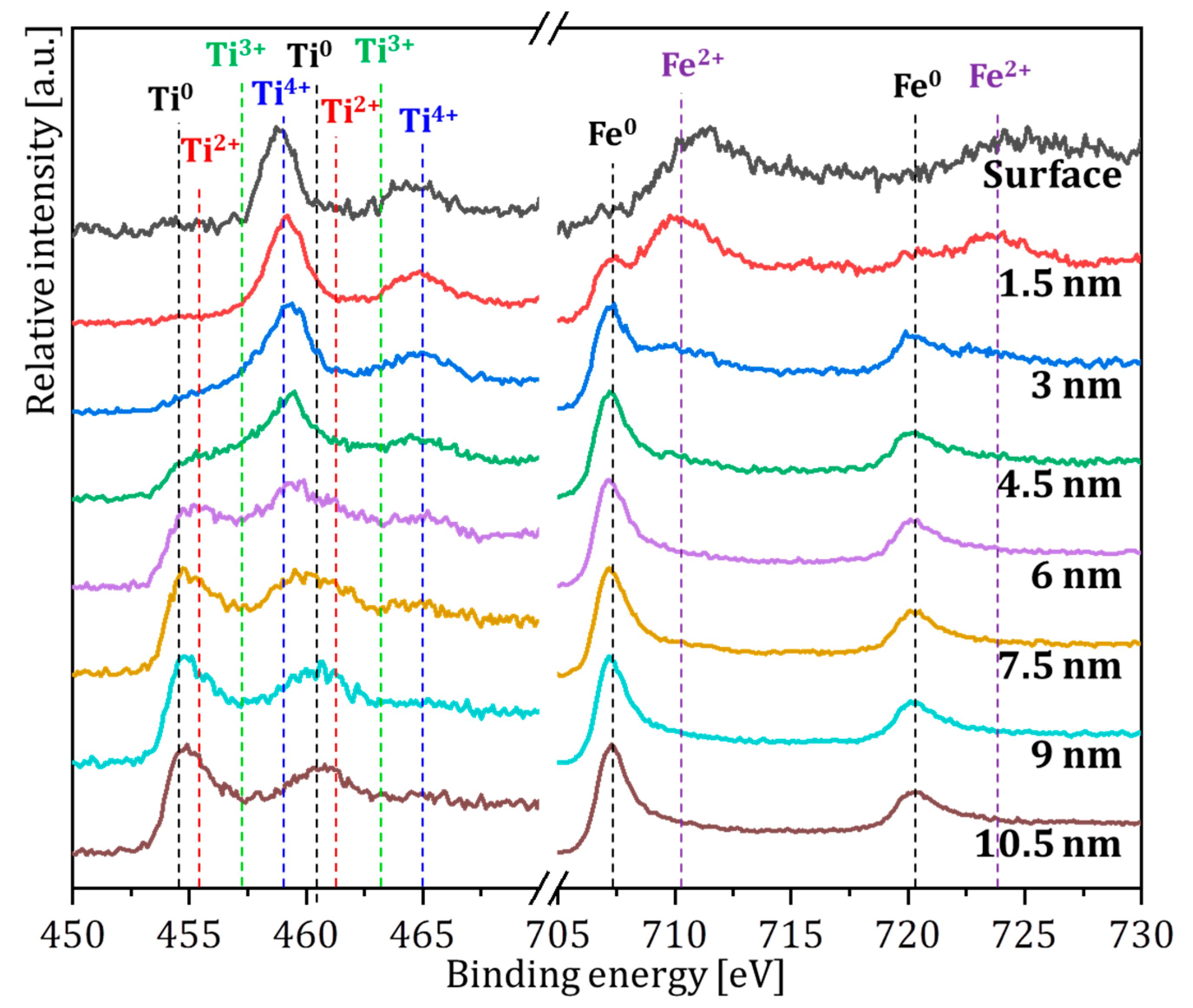
Thermodynamic differences between Ti and Fe, in terms of the surface Gibbs free energy and oxide formation enthalpy, suggest the preferential oxidation of Ti first followed by that of Fe [37]. The surface of the as-cast reference alloy is thus likely to display a complex oxidation state, as illustrated by its XPS depth profiling (Figure 2). The surface region thus showed typical Fe2+ (at ~711.4 and ~725 eV [28,38]) and Ti4+ (at ~458.7 and ~464.7 eV [28,38,39]) peaks, indicating the existence of a surface Fe–Ti complex oxide as per recent findings [40]. The progressive etching of the sample revealed the first the occurrence of metallic Fe (Fe0, at ~707 eV [28,41]) right below the surface (1.5 nm depth), closely followed by that of Ti3+ (at ~457.5 and ~463.5 eV [39,42]) and Ti2+ (at ~455.9 and ~461.7 eV [39,42]) as we moved deeper (at 4.5 nm). Note that the major contribution for the Ti2p spectrum was attributed to Ti2+, since Ti3+ was barely noticeable in all spectra. Further down (at 6 nm), all Fe existed in the form of metal and the first occurrence of metallic Ti could be observed (Ti0, at ~454.1 and ~460.3 eV) [39,43]. Eventually, all Ti oxides vanished as the Ti4+ peak went extinct at 7.5 nm. There, the metallic contribution was overall predominant, and the oxide layer was confirmed to be <7.5 nm thick, consistent with earlier TEM observations (6 nm). This depth profile showed the gradual oxygen depletion from the surface-to-bulk, along with the progressive evolution of oxide species: (i) complex Ti–Fe-oxide covering (ii) a region of mixed ionic states (Ti2+/Ti4+ oxidation states and metallic Fe) over (iii) the TiFe bulk.
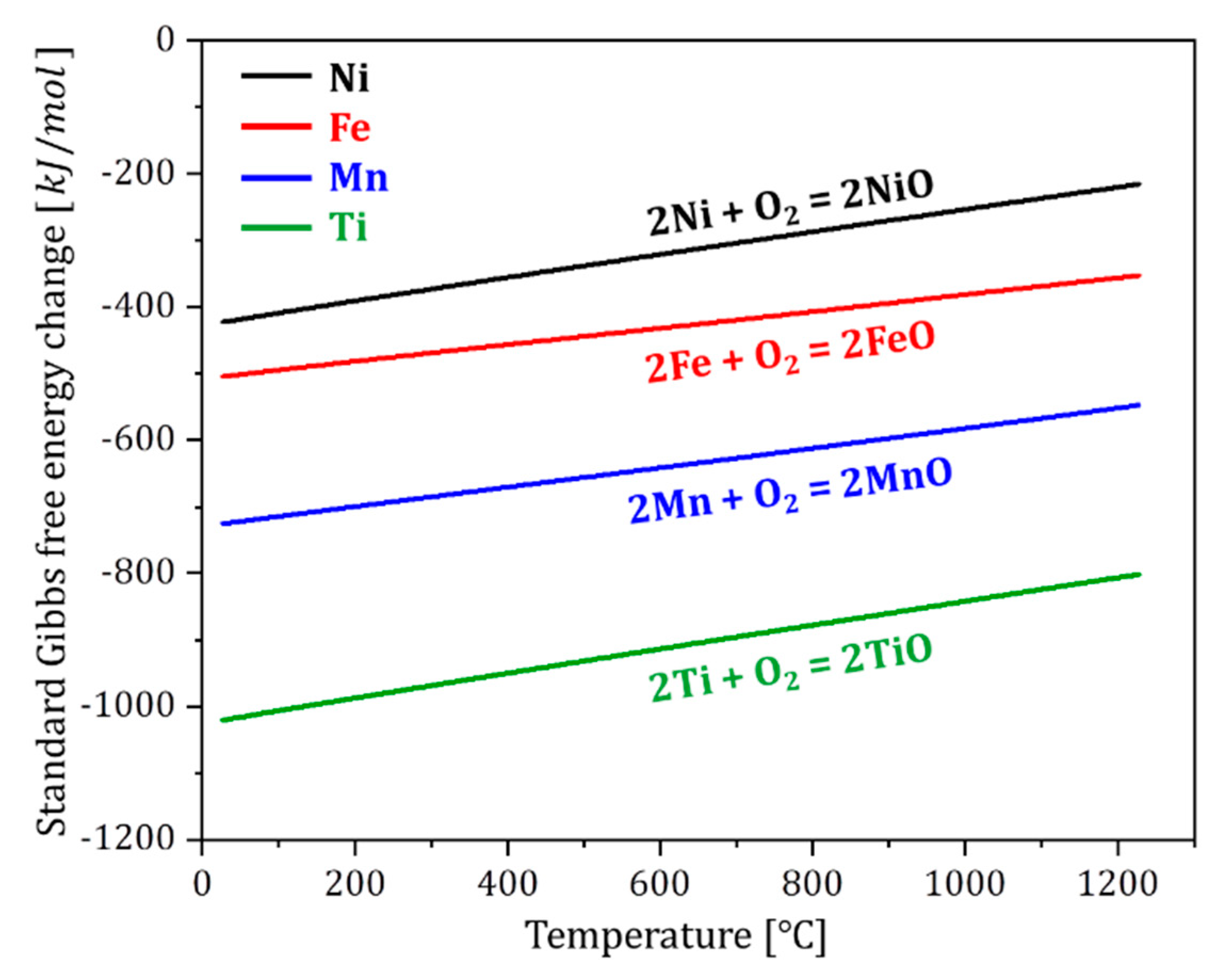
Although Ni and Mn substitution for Fe are expected to result in depth profiles comparable to that of the as-cast TiFe, notably in terms of the progressive reduction in the oxygen concentration along with increasing depth, such chemical modification will nevertheless impact the composition of the oxide layer in light of differences in the oxidation potential of substitution elements. Indeed, the Ellingham diagram of Ti, Fe, Ni, and Mn calculated by Thermo-Calc (Figure 3), together with the absolute values of the oxidation driving force for each element, clearly illustrate the possible chemical composition changes in the surface oxide film. Here, Ti turned out to have the strongest oxidation driving force among the studied elements (Ti > Mn > Fe > Ni), and this tendency was maintained regardless of the temperature. The Ellingham diagram therefore suggests that Ti will mainly compose the surface oxide film as the temperature increases. Furthermore, given that Ni has a smaller oxidation driving force than Fe while that of Mn is stronger, the effect of Ni and Mn elemental substitution for Fe on the nature of the surface oxide is rather straightforward, however, its role in the evolution of oxide species under thermal activation conditions is yet to be documented.
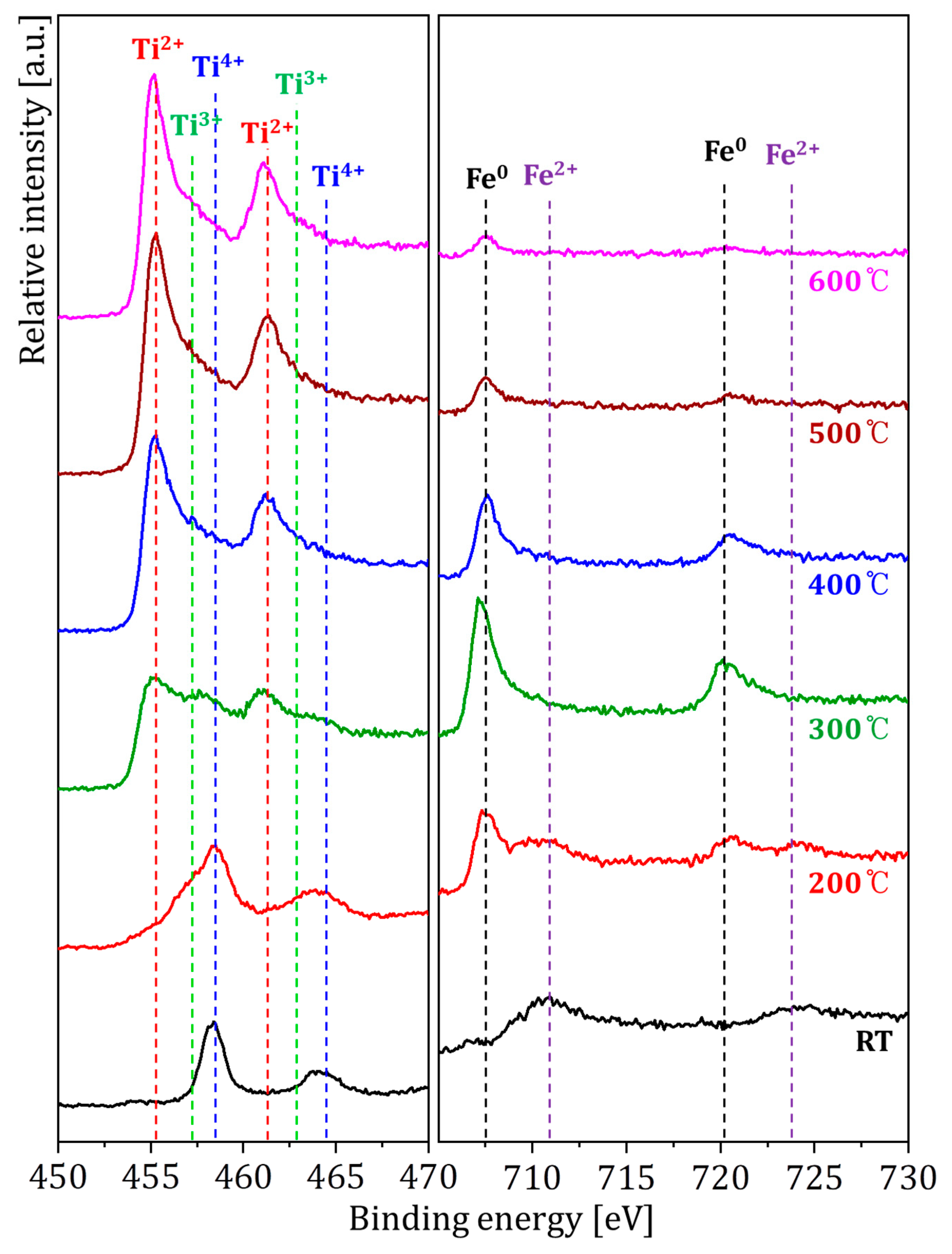
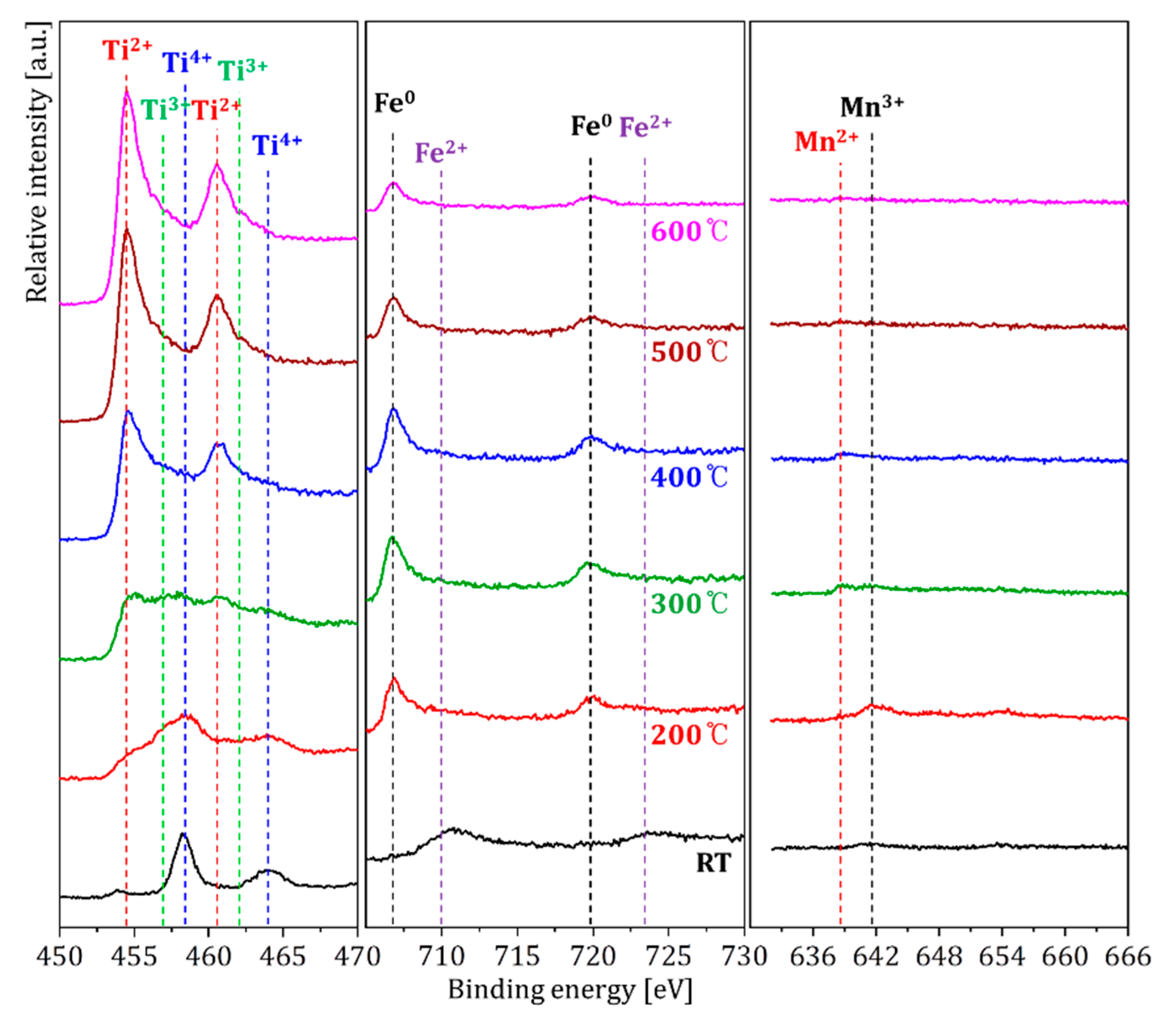
For the purpose of directly monitoring the evolution of the thin oxide film during heat treatment, in situ XPS was then performed at temperatures ranging from room temperature to 600 °C for the reference and substituted alloys (Figure 4, Figure 5 and Figure 6). The initial mixed ionization state of the as-cast TiFe alloy at RT, characterized by Ti4+ and Fe2+ peaks, started to experience changes at a temperature as low as 200 °C (Figure 4). A slight broadening of Ti2+ peaks could be observed, indicating the initiation of TiO2 reduction. In parallel, the first occurrence of Fe0 could be noted, coexisting with Fe2+. By rising the temperature to 300 °C, the multiplicity of the Ti valence state became even clearer as the peak noticeably broadened. Ti2+ made its first apparition and mostly contributed to the observed peak, while Ti4+ decreased significantly. Due to the broad aspect of the Ti2p spectra, it is rather difficult to claim a substantial contribution from the Ti3+ state, nevertheless, its existence can be assumed considering the tiny shoulder observed. Furthermore, Fe2p was dominated by Fe0, since the contribution from Fe2+ was negligible. At 400 °C, all Ti seemed to be in the Ti2+ state (although it was difficult to tell if Ti3+ remained due to the peak broadness), while Fe was mostly metallic (Fe0). Beyond this point (for 500–600 °C), Ti2+ intensified and Ti4+ vanished, whereas the relative Fe0 contribution appeared to decrease due to possible Ti enrichment of the surface [34], which is also suggested by earlier results (Figure 3).
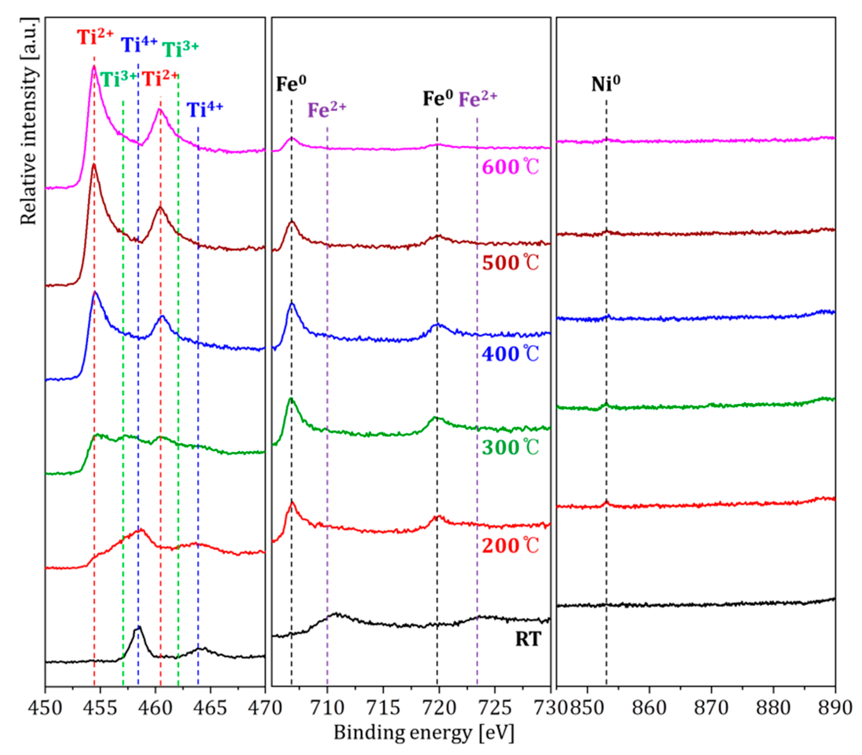
A closer look at in situ results of the Ni- and Mn-substituted alloys (Figure 5 and Figure 6, respectively) revealed that substitution did not alter the reduction pathway of the TiFe single phase. Indeed, not only were the same Ti and Fe ionic states indexed, but they were also found to be reduced through steps and at temperatures consistent with those described for the unmodified TiFe (Figure 4). There was thus no major difference with the reference specimen, except for the presence of Ni and Mn peaks, which are characterized by weaker intensities compared to those observed for the base Ti and Fe atoms due to the relatively small substitution amount utilized in this study. In addition, at room temperature, Mn was found to exist in the Mn3+ state (at 640.8 eV [44]), which partially reduced to Mn2+ (~639.4 eV [44]) upon a temperature increase to 300 °C. From 400 °C, the Mn3+ state completely disappeared in favor of Mn2+. For TiFe0.9Ni0.1, on the other hand, only metallic Ni (Ni0, at 852.1 eV [45]) was present throughout heating considering that Ni had the smallest oxidation driving force among the four constituting elements (as shown earlier in Figure 3). Overall, both the thermodynamic calculations and in situ heating experiments indicate that Fe and Ni eventually coexist in the metallic state, while Ti and Mn remain ionized even after heating.
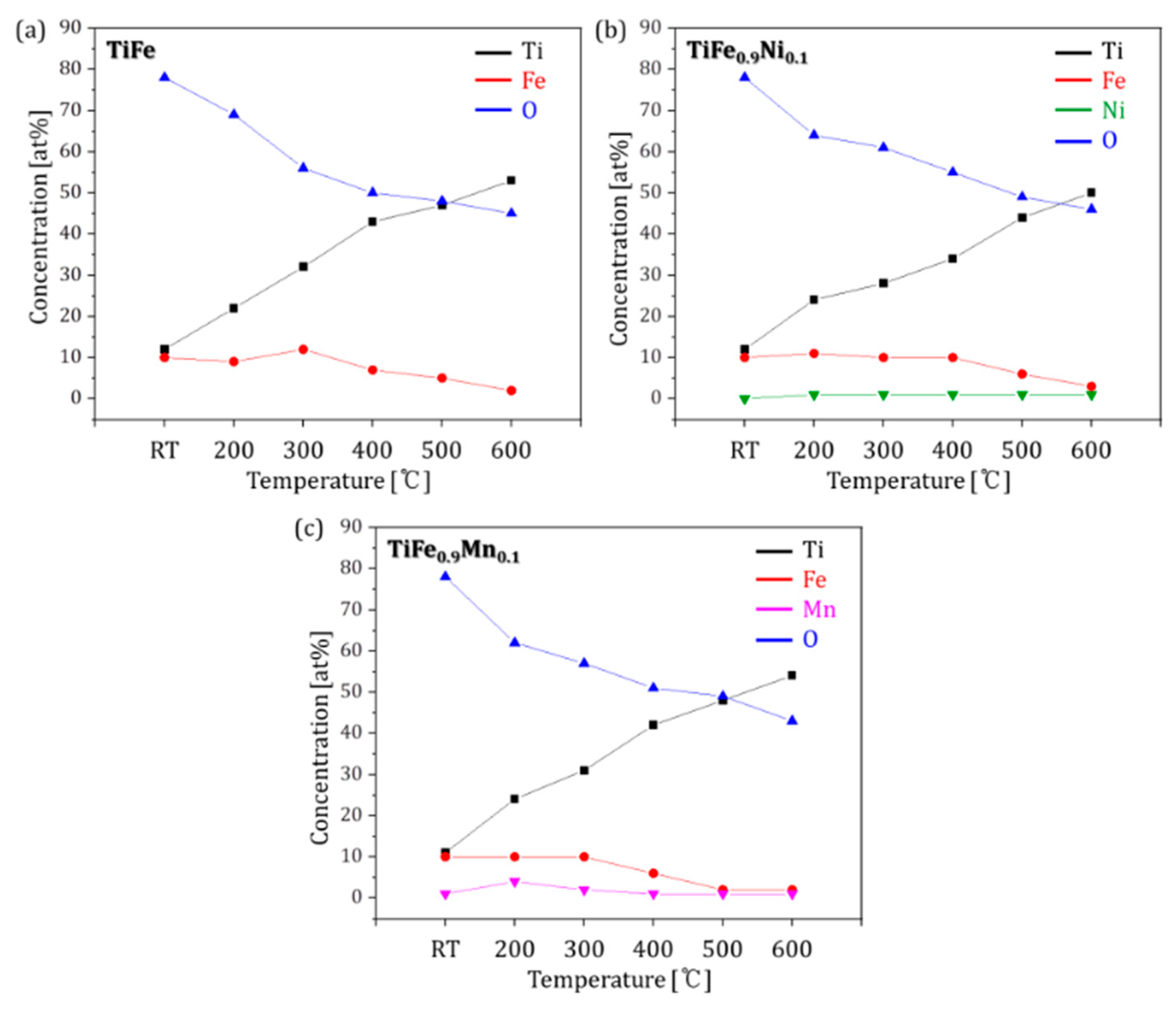
Such a difference, ascribed to the differences in the oxidation potentials foreseen by thermodynamic calculations, is inherently reflected in the composition of the surface species (as shown in Figure 7 and Table 1, summarizing the composition evolution of TiFe, TiFe0.9Ni0.1 and TiFe0.9Mn0.1 as a function of temperature). For instance, the Ni content in TiFe0.9Ni0.1 was rather small and remained almost constant, while that of Mn in TiFe0.9Md0.1 fluctuates in a noticeable way: a slight increase at 200 °C, a decrease from 300 °C, and a low content beyond 400 °C. At RT, the compositions of the TiFe, TiFe0.9Ni0.1, and TiFe0.9Mn0.1 surfaces were found to be Ti12Fe10O78, Ti12Fe10O78, and Ti11Fe10Mn1O78, respectively. As the temperature increased to 600 °C, the oxygen concentration decreased and resulted in surface compositions of Ti53Fe2O45, Ti50Fe3Ni1O46, and Ti54Fe2Mn1O43, respectively.
The gradual reduction in the initial Ti and Fe mixed oxides shown above consistently illustrates the dissolution of oxygen and its diffusion into the bulk, thermodynamically favorable under the current measurement conditions (ultra-high vacuum and high temperature [34]). In the absence of oxygen partial pressure, the Ti oxide protective layer is dissolved and produces metallic Ti, only if the temperature is higher than 350 °C [33]. In our results, although Ti is not completely reduced to metallic Ti due to the limited measurement time (30 min), we can nevertheless still pinpoint a comparable critical temperature of 400 °C for which the alloys predominantly shift toward a metallic character as Ti reduction initiates, regardless of the specimen composition. Hence, the in situ results unfortunately do not provide any evidence to claim the beneficial role of Ni or Mn on the reduction pathway (i.e., no noticeable decrease in the temperature required for oxygen dissolution), and the reduced surface turned out to be rather unstable, since even a brief exposure to air was observed to revert the surface back to its initial inert state (see Supplementary Figure S2 and earlier reports [33,34]).
Strictly speaking, a reduced TiFe surface is not the sole condition for activation, and the formation of secondary phases (Fe2Ti, excess Ti, TiFe-based oxides), whether induced by substitution or not, can also actively contribute to the first hydrogenation by creating prime/secondary phase interfaces and by lowering the fracture toughness of TiFe [7]. Furthermore, the introduction of secondary C14 Laves phase also remarkably illustrates this point by further enhancing the first hydrogen absorption properties [11,20,46,47]. Interestingly, the ability to form a secondary phase greatly differed from one substitution element to another, and consequently so did the first hydrogen absorption behavior. Indeed, while up to 30% Ni substitution for Fe (TiFe0.7Ni0.3) did not affect the TiFe (B2) single phase, Mn-substituted alloys tended to develop a dual B2-C14 Laves phase nature from as low as 20% of elemental substitution, and were demonstrated to readily absorb hydrogen whereas single phase systems could not (regardless of the composition of surface oxides) [11,20,46]. Furthermore, recent density functional theory (DFT) calculations for single phase TiFe0.9M0.1 (M = Ni, Mn) indicate the higher stability of hydrides formed for alloys modified with Ni (hydrogen desorption pressure of 1.4 bar at 50 °C with a hydride decomposition enthalpy of −33.229 kJ·mol−1 H2, against 6.5 bar and −23.843 kJ·mol−1 H2 for Mn-substituted alloys) [6], suggesting the better suitability of Mn substitution for actual power-to-gas (P2G) applications, notably in terms of practical service conditions (~6 and ~2 bar H2 for absorption and desorption, respectively [48,49,50]). In light of the promising potential of the TiFe0.8Mn0.2 alloy in terms of both activation and minor change in the hydride formation enthalpy compared to pristine TiFe (−22.976 kJ·mol−1 H2 [6]), providing further in-depth investigations, notably by performing in-situ heating XPS measurement, would be of great interest to further comprehend and document the first hydrogenation properties of this type of alloy.

4. Conclusions

The evolution of the TiFe surface oxide species was investigated by XRD, TEM as well as combined XPS depth profiling and in situ heating. Observations show the existence of a composite amorphous oxide layer on the surface, characterized by a mixture of Ti4+ and Fe2+ covering a region of metallic Fe and mixed Ti oxidation states whose presence passivates the underlying TiFe intermetallic. The thermal activation conditions, reproduced by in situ heating, are shown to partially reduce Ti oxides under the experimental parameters. The overall shift toward metallic character (i.e., when Ti starts to be reduced), was found at 400 °C, whether pristine TiFe, TiFe0.9Ni0.1, or TiFe0.9Mn0.1 were investigated. Higher temperatures did not alter the surface valence state any further, confirming why TiFe activation is mostly carried out around 400 °C. Although TiFe0.9Ni0.1 and TiFe0.9Mn0.1 displayed similar trends, Ni was found to exist as metallic Ni in the surface oxide film from 200 °C and throughout heating due to its low oxidation potential, whereas the Mn valence state changed from Mn3+ to Mn2+ given its comparatively stronger oxidation potential. Considering the superior potential for industrial applications of Mn substitution for Fe, providing additional insights into the evolution of the surface oxides of dual phase TiFeMn-based alloys during the activation process could be of great interest to better comprehend this fascinating system.

Supplementary Materials

The following are available online at https://www.mdpi.com/article/10.3390/met12122093/s1, Figure S1: Structural characterization of the as-cast TiFe0.9Mn0.1 and TiFe0.9Ni0.1 alloys obtained by X-ray diffraction (XRD), Figure S2: In situ heating X-ray photoelectron spectroscopy (XPS) of the TiFe surface observed from room temperature (RT), 400 °C and after air exposure.

Author Contributions

Writing-original draft preparation, formal analysis and review and editing, K.B.P.; Writing-original draft preparation and review and editing, J.O.F.; Formal analysis and validation, J.-S.B.; Formal analysis and methodology, G.B.K.; Formal analysis and methodology, J.I.C.; Conceptualization, Y.D.K.; Writing-original draft preparation and funding acquisition, T.-W.N.; Supervision and funding acquisition, H.-K.P. All authors have read and agreed to the published version of the manuscript.

Funding

This research was supported by the National Research Foundation of Korea (NRF) funded by the Ministry of Science and ICT (Grant Nos. 2019M3E6A1103910 and 2022M3D1A2095316) and the Ministry of Trade, Industry, and Energy through the machinery and equipment industry technology development project (Grant No. 20018661).

Conflicts of Interest

The authors declare that they have no known competing financial interests or personal relationships that could have appeared to influence the work reported in this paper.

References

  1. Abe, J.O.; Popoola, A.; Ajenifuja, E.; Popoola, O. Hydrogen energy, economy and storage: Review and recommendation. Int. J. Hydrogen Energy 2019, 44, 15072–15086. [Google Scholar] [CrossRef]
  2. Rusman, N.A.A.; Dahari, M. A review on the current progress of metal hydrides material for solid-state hydrogen storage applications. Int. J. Hydrogen Energy 2016, 41, 12108–12126. [Google Scholar] [CrossRef]
  3. Moroz, S.; Tan, X.F.; Pierce, J.; Greaves, M.; Duguid, A.; Dumur, K.; Ng, J. Systems based on hypo-eutectic Mg–Mg2Ni alloys for medium to large scale hydrogen storage and delivery. J. Alloys Compd. 2013, 580, S329–S332. [Google Scholar] [CrossRef]
  4. Reilly, J.J.; Wiswall, R.H. Formation and Properties of Iron Titanium Hydride. Inorg. Chem. 1974, 13, 218–222. [Google Scholar] [CrossRef]
  5. Lys, A.; Fadonougbo, J.O.; Faisal, M.; Suh, J.-Y.; Lee, Y.-S.; Shim, J.-H.; Park, J.; Cho, Y.W. Enhancing the Hydrogen Storage Properties of AxBy Intermetallic Compounds by Partial Substitution: A Short Review. Hydrogen 2020, 1, 38–63. [Google Scholar] [CrossRef]
  6. Fadonougbo, J.O.; Park, K.B.; Na, T.-W.; Park, C.-S.; Park, H.-K.; Ko, W.-S. An integrated computational and experimental method for predicting hydrogen plateau pressures of TiFe1-xMx-based room temperature hydrides. Int. J. Hydrogen Energy 2022, 47, 17673–17682. [Google Scholar] [CrossRef]
  7. Sandrock, G.D.; Reilly, J.J.; Johnson, J.R. Metallurgical considerations in the production and use of FeTi alloys for hydrogen storage. In Proceedings of the 11th Intersociety Energy Conversion Engineering Conference, State Line, NV, USA, 12 September 1976. [Google Scholar]
  8. Zhang, Y.-H.; Li, C.; Yuan, Z.-M.; Qi, Y.; Guo, S.-H.; Zhao, D.-L. Research progress of TiFe-based hydrogen storage alloys. J. Iron Steel Res. Int. 2022, 29, 537–551. [Google Scholar] [CrossRef]
  9. Mintz, M.; Vaknin, S.; Biderman, S.; Hadari, Z. Hydrides of ternary TiFexM1−x (M = Cr, Mn, Co, Ni) intermetallics. J. Appl. Phys. 1981, 52, 463–467. [Google Scholar] [CrossRef]
  10. Jain, P.; Gosselin, C.; Huot, J. Effect of Zr, Ni and Zr7Ni10 alloy on hydrogen storage characteristics of TiFe alloy. Int. J. Hydrogen Energy 2015, 40, 16921–16927. [Google Scholar] [CrossRef]
  11. Park, K.B.; Fadonougbo, J.O.; Park, C.-S.; Lee, J.-H.; Na, T.-W.; Kang, H.-S.; Ko, W.-S.; Park, H.-K. Effect of Fe substitution on first hydrogenation kinetics of TiFe-based hydrogen storage alloys after air exposure. Int. J. Hydrogen Energy 2021, 46, 30780–30789. [Google Scholar] [CrossRef]
  12. Lee, S.-M.; Perng, T.-P. Correlation of substitutional solid solution with hydrogenation properties of TiFe1−xMx (M = Ni, Co, Al) alloys. J. Alloys Compd. 1999, 291, 254–261. [Google Scholar] [CrossRef]
  13. Zadorozhnyy, V.Y.; Klyamkin, S.; Zadorozhnyy, M.Y.; Bermesheva, O.; Kaloshkin, S. Mechanical alloying of nanocrystalline intermetallic compound TiFe doped by aluminum and chromium. J. Alloys Compd. 2014, 586, S56–S60. [Google Scholar] [CrossRef]
  14. Dematteis, E.M.; Cuevas, F.; Latroche, M. Hydrogen storage properties of Mn and Cu for Fe substitution in TiFe0.9 intermetallic compound. J. Alloys Compd. 2021, 851, 156075. [Google Scholar] [CrossRef]
  15. Ali, W.; Hao, Z.; Li, Z.; Chen, G.; Wu, Z.; Lu, X.; Li, C. Effects of Cu and Y substitution on hydrogen storage performance of TiFe0.86Mn0.1Y0.1−xCux. Int. J. Hydrogen Energy 2017, 42, 16620–16631. [Google Scholar] [CrossRef]
  16. Patel, A.K.; Duguay, A.; Tougas, B.; Schade, C.; Sharma, P.; Huot, J. Microstructure and first hydrogenation properties of TiFe alloy with Zr and Mn as additives. Int. J. Hydrogen Energy 2020, 45, 787–797. [Google Scholar] [CrossRef]
  17. Dematteis, E.M.; Dreistadt, D.M.; Capurso, G.; Jepsen, J.; Cuevas, F.; Latroche, M. Fundamental hydrogen storage properties of TiFe-alloy with partial substitution of Fe by Ti and Mn. J. Alloys Compd. 2021, 874, 159925. [Google Scholar] [CrossRef]
  18. Yang, T.; Wang, P.; Xia, C.; Liu, N.; Liang, C.; Yin, F.; Li, Q. Effect of chromium, manganese and yttrium on microstructure and hydrogen storage properties of TiFe-based alloy. Int. J. Hydrogen Energy 2020, 45, 12071–12081. [Google Scholar] [CrossRef]
  19. Jung, J.Y.; Lee, S.-I.; Faisal, M.; Kim, H.; Lee, Y.-S.; Suh, J.-Y.; Shim, J.-H.; Huh, J.-Y.; Cho, Y.W. Effect of Cr addition on room temperature hydrogenation of TiFe alloys. Int. J. Hydrogen Energy 2021, 46, 19478–19485. [Google Scholar] [CrossRef]
  20. Lee, S.-M.; Perng, T.-P. Effect of the second phase on the initiation of hydrogenation of TiFe1−xMx (M = Cr, Mn) alloys. Int. J. Hydrogen Energy 1994, 19, 259–263. [Google Scholar] [CrossRef]
  21. Kim, H.; Faisal, M.; Lee, S.-I.; Jung, J.Y.; Kim, H.-J.; Hong, J.; Lee, Y.-S.; Shim, J.-H.; Cho, Y.W.; Kim, D.H. Activation of Ti–Fe–Cr alloys containing identical AB2 fractions. J. Alloys Compd. 2021, 864, 158876. [Google Scholar] [CrossRef]
  22. Emami, H.; Edalati, K.; Matsuda, J.; Akiba, E.; Horita, Z. Hydrogen storage performance of TiFe after processing by ball milling. Acta Mater. 2015, 88, 190–195. [Google Scholar] [CrossRef]
  23. Chiang, C.H.; Chin, Z.H.; Perng, T.P. Hydrogenation of TiFe by high-energy ball milling. J. Alloys Compd. 2000, 307, 259–265. [Google Scholar] [CrossRef]
  24. Edalati, K.; Matsuda, J.; Yanagida, A.; Akiba, E.; Horita, Z. Activation of TiFe for hydrogen storage by plastic deformation using groove rolling and high-pressure torsion: Similarities and differences. Int. J. Hydrogen Energy 2014, 39, 15589–15594. [Google Scholar] [CrossRef]
  25. Edalati, K.; Matsuda, J.; Iwaoka, H.; Toh, S.; Akiba, E.; Horita, Z. High-pressure torsion of TiFe intermetallics for activation of hydrogen storage at room temperature with heterogeneous nanostructure. Int. J. Hydrogen Energy 2013, 38, 4622–4627. [Google Scholar] [CrossRef]
  26. Vega, L.; Leiva, D.; Neto, R.L.; Silva, W.; Silva, R.; Ishikawa, T.; Kiminami, C.; Botta, W. Mechanical activation of TiFe for hydrogen storage by cold rolling under inert atmosphere. Int. J. Hydrogen Energy 2018, 43, 2913–2918. [Google Scholar] [CrossRef]
  27. Zadorozhnyy, V.Y.; Milovzorov, G.; Klyamkin, S.; Zadorozhnyy, M.Y.; Strugova, D.; Gorshenkov, M.; Kaloshkin, S. Preparation and hydrogen storage properties of nanocrystalline TiFe synthesized by mechanical alloying. Prog. Nat. Sci. Mater. Int. 2017, 27, 149–155. [Google Scholar] [CrossRef]
  28. Zhu, H.; Wu, J.; Wang, Q. Reactivation behaviour of TiFe hydride. J. Alloys Compd. 1994, 215, 91–95. [Google Scholar] [CrossRef]
  29. Dematteis, E.M.; Berti, N.; Cuevas, F.; Latroche, M.; Baricco, M. Substitutional effects in TiFe for hydrogen storage: A comprehensive review. Mater. Adv. 2021, 2, 2524–2560. [Google Scholar] [CrossRef]
  30. Gosselin, C.; Santos, D.; Huot, J. First hydrogenation enhancement in TiFe alloys for hydrogen storage. J. Phys. D Appl. Phys. 2017, 50, 375303. [Google Scholar] [CrossRef]
  31. Ulate-Kolitsky, E.; Tougas, B.; Neumann, B.; Schade, C.; Huot, J. First hydrogenation of mechanically processed TiFe-based alloy synthesized by gas atomization. Int. J. Hydrogen Energy 2021, 46, 7381–7389. [Google Scholar] [CrossRef]
  32. Patel, A.K.; Duguay, A.; Tougas, B.; Neumann, B.; Schade, C.; Sharma, P.; Huot, J. Study of the Microstructural and First Hydrogenation Properties of TiFe Alloy with Zr, Mn and V as Additives. Processes 2021, 9, 1217. [Google Scholar] [CrossRef]
  33. Schober, T.; Westlake, D. The activation of FeTi for hydrogen storage-A different view. Scr. Metall. 1981, 15, 913–918. [Google Scholar] [CrossRef]
  34. Schlapbach, L.; Riesterer, T. The activation of FeTi for hydrogen absorption. Appl. Phys. A 1983, 32, 169–182. [Google Scholar] [CrossRef]
  35. Modi, P.; Aguey-Zinsou, K.-F. Titanium-iron-manganese (TiFe0.85Mn0.15) alloy for hydrogen storage: Reactivation upon oxidation. Int. J. Hydrog. Energy 2019, 44, 16757–16764. [Google Scholar] [CrossRef]
  36. Lin, H.-J.; Li, H.-W.; Shao, H.; Lu, Y.; Asano, K. In situ measurement technologies on solid-state hydrogen storage materials: A review. Mater. Today Energy 2020, 17, 100463. [Google Scholar] [CrossRef]
  37. Faisal, M.; Suh, J.-Y.; Lee, Y.-S. Understanding first cycle hydrogenation properties of Ti–Fe–Zr ternary alloys. Int. J. Hydrogen Energy 2021, 46, 4241–4251. [Google Scholar] [CrossRef]
  38. Madian, M.; Wang, Z.; Gonzalez-Martinez, I.; Oswald, S.; Giebeler, L.; Mikhailova, D. Ordered Ti-Fe-O nanotubes as additive-free anodes for lithium ion batteries. Appl. Mater. Today 2020, 20, 100676. [Google Scholar] [CrossRef]
  39. Chávez-Díaz, M.P.; Luna-Sánchez, R.M.; Vazquez-Arenas, J.; Lartundo-Rojas, L.; Hallen, J.M.; Cabrera-Sierra, R. XPS and EIS studies to account for the passive behavior of the alloy Ti-6Al-4V in Hank’s solution. J. Solid State Electrochem. 2019, 23, 3187–3196. [Google Scholar] [CrossRef]
  40. Modi, P.; Liu, W.; Aguey-Zinsou, K.-F. Effect of chromium addition on the reactivation of the titanium-iron-manganese (TiFe0.85Mn0.15) alloy. J. Alloys Compd. 2022, 891, 161943. [Google Scholar] [CrossRef]
  41. Wu, X.; Chen, C.; Hao, J.; Zhao, T.; Ma, H.; Lu, Y.; Ren, Z. Effect of Phosphating and Heat Treatment on Magnetic Properties of Fe-3.3 Si-6.5 Cr Soft Magnetic Composites. J. Supercond. Nov. Magn. 2020, 33, 1889–1897. [Google Scholar] [CrossRef]
  42. Atuchin, V.V.; Kesler, V.G.; Pervukhina, N.V.; Zhang, Z. Ti 2p and O 1s core levels and chemical bonding in titanium-bearing oxides. J. Electron Spectrosc. Relat. Phenom. 2006, 152, 18–24. [Google Scholar] [CrossRef]
  43. Biesinger, M. X-ray Photoelectron Spectroscopy (XPS) Reference Pages; Surface Science Western, University of Western Ontario: London, ON, Canada, 2015. [Google Scholar]
  44. Pan, R.; Li, Y.; Fang, F.; Cao, W.; Heb, Y. Surface valence states of Mn ions and magnetic properties of La0.67Sr0.33MnO3 films. Int. J. Mater. Sci. Appl. 2016, 5, 222–227. [Google Scholar]
  45. Hengne, A.M.; Samal, A.K.; Enakonda, L.R.; Harb, M.; Gevers, L.E.; Anjum, D.H.; Hedhili, M.N.; Saih, Y.; Huang, K.-W.; Basset, J.-M. Ni–Sn-supported ZrO2 catalysts modified by indium for selective CO2 hydrogenation to methanol. ACS Omega 2018, 3, 3688–3701. [Google Scholar] [CrossRef] [PubMed] [Green Version]
  46. Park, K.B.; Ko, W.-S.; Fadonougbo, J.O.; Na, T.-W.; Im, H.-T.; Park, J.-Y.; Kang, J.-W.; Kang, H.-S.; Park, C.-S.; Park, H.-K. Effect of Fe substitution by Mn and Cr on first hydrogenation kinetics of air-exposed TiFe-based hydrogen storage alloy. Mater. Charact. 2021, 178, 111246. [Google Scholar] [CrossRef]
  47. Park, K.B.; Fadonougbo, J.O.; Na, T.-W.; Lee, T.W.; Kim, M.; Lee, D.H.; Kwon, H.G.; Park, C.-S.; Kim, Y.D.; Park, H.-K. On the first hydrogenation kinetics and mechanisms of a TiFe0.85Cr0.15 alloy produced by gas atomization. Mater. Charact. 2022, 192, 112188. [Google Scholar] [CrossRef]
  48. Clarke, R.; Giddey, S.; Badwal, S. Stand-alone PEM water electrolysis system for fail safe operation with a renewable energy source. Int. J. Hydrogen Energy 2010, 35, 928–935. [Google Scholar] [CrossRef]
  49. Lee, S.Y.; Ryu, J.-H.; Lee, I.-B. Feasibility Analysis of Integrated Power-to-Ammonia Processes Employing Alkaline Electrolysis and Air Separation. J. Chem. Eng. Jpn. 2022, 55, 51–60. [Google Scholar] [CrossRef]
  50. Toghyani, S.; Afshari, E.; Baniasadi, E. A parametric comparison of three fuel recirculation system in the closed loop fuel supply system of PEM fuel cell. Int. J. Hydrogen Energy 2019, 44, 7518–7530. [Google Scholar] [CrossRef]
Figure 1. Structural characterization of the as-cast TiFe alloy obtained by X-ray diffraction (XRD) (a), cross-sectional transmission electron microscopy (TEM) (b), and selected area diffraction patterns (SADPs) of both the thin surface oxide film (c) and the TiFe bulk (d).
Metals 12 02093 g001
Figure 2. X-ray photoelectron spectroscopy (XPS) depth profile of the reference TiFe sample.
Metals 12 02093 g002
Figure 3. The Ellingham diagram of Ti, Fe, Ni, and Mn calculated by Thermo-Calc.
Metals 12 02093 g003
Figure 4. In situ heating X-ray photoelectron spectroscopy (XPS) of the TiFe surface observed from room temperature (RT) to 600 °C.
Metals 12 02093 g004
Figure 5. In situ heating X-ray photoelectron spectroscopy (XPS) of the TiFe0.9Ni0.1 surface observed from room temperature (RT) to 600 °C.
Metals 12 02093 g005
Figure 6. In situ heating X-ray photoelectron spectroscopy (XPS) of the TiFe0.9Mn0.1 surface observed from room temperature (RT) to 600 °C.
Metals 12 02093 g006
Figure 7. The composition evolution in the (a) TiFe, (b) TiFe0.9Ni0.1, and (c) TiFe0.9Mn0.1 alloys during in situ heating X-ray photoelectron spectroscopy (XPS).
Metals 12 02093 g007
Table 1. The Ni0.1 and TiFe0.9Mn0.1 alloys during in situ heating X-ray photoelectron spectroscopy (XPS).
TemperaturesComposition (at. %)
TiFeTiFe0.9Ni0.1TiFe0.9Mn0.1
Room Temperature (RT)Ti12Fe10O78Ti12Fe10O78Ti11Fe10Mn1O78
200 °CTi22Fe9O69Ti24Fe11Ni1O64Ti24Fe10Mn4O62
300 °CTi32Fe12O56Ti28Fe10Ni1O61Ti31Fe10Mn2O57
400 °CTi43Fe7O50Ti34Fe10Ni1O55Ti42Fe6Mn1O51
500 °CTi47Fe5O48Ti44Fe6Ni1O49Ti48Fe2Mn1O49
600 °CTi53Fe2O45Ti50Fe3Ni1O46Ti54Fe2Mn1O43
Publisher’s Note: MDPI stays neutral with regard to jurisdictional claims in published maps and institutional affiliations.