Abstract
Diamond-like carbon (DLC) films are widely used in key parts of nuclear reactors as a protective coating. A study on the abrasive wear property of Cr/W-DLC/DLC multilayer films was performed at various temperatures. Results show that the mechanism of impact wear under no sand condition is mainly plastic deformation. The multilayer film still has excellent impact wear resistance and favorable adhesion with 308L stainless steel substrate at elevated temperatures under no sand conditions. Sand particles destroy the surface of the multilayer film due to the effect of cutting and ploughing, leading to a nine-fold increase in the wear area. The impact wear mechanism changes into abrasive wear with sand addition. Oxidation wear exists on 308L stainless steel substrate material due to the removal of the multilayer film at high temperatures. More energy is absorbed for plastic deformation and material removal under sand conditions, resulting in lower rebound velocity and peak contact force than under no sand conditions. The temperature leads to the softening of the substrate; thus, the specimens become more prone to plastic deformation and material removal.
1. Introduction
Impact wear is common in nuclear power plants and aero-engines [1,2]. According to statistics, more than 50% of fuel failure in nuclear power is caused by debris-fretting impact. The debris comes from impurities (stainless-steel peel-offs, buckle, sand, etc.) in the coolant flow. The high-temperature components in the aero-engine are also damaged by impact with foreign objects (solid particles in the fluid medium, such as sand, dust, ash, etc.) [3,4]. Therefore, finding high-temperature materials with impact and wear resistance is important in the nuclear power and aerospace industry.
Diamond-like carbon (DLC) film is an amorphous film mainly composed of sp3 carbon atoms with a diamond structure and sp2 carbon atoms with a graphite structure. Due to its structure, it has excellent properties similar to diamond, such as high hardness, excellent chemical inertia, low friction coefficient, good wear resistance, and high elastic modulus. Therefore, DLC films have been applied to key parts in aero-engines, nuclear reactors, space stations, and other fields to improve the service life of these parts in recent years [5,6,7,8]. There have been many reports on the tribological behavior and mechanism of DLC at high temperatures [9,10,11,12,13]. In addition, many experiments show that doping W elements in the preparation of DLC films (W-DLC) can improve the high-temperature tribological properties and thermal stability of DLC films [14,15,16].
Many studies on the thermal stability and high-temperature friction, and wear of W-DLC films have been conducted [17,18,19]. Zhan et al. systematically studied the tribological behavior of W-DLC films at high temperatures from 25 °C to 500 °C. The results show that the structure and tribological properties of W-DLC films remain stable at 200 °C. Graphitization and oxidation of carbon, observed at 300 °C, reduce the wear resistance of DLC films. The formation of WO3 was detected on the worn surface above 400 °C. The coefficient of friction (COF) at 500 °C is as low as 0.15, whereas the wear rate is much higher than at 200 °C [20]. Gharam et al. studied the tribological behavior of W-DLC as a function of testing temperatures up to 500 °C. The results show a low COF of 0.2 at 25 °C, whereas a high average steady-state COF of 0.60 was recorded between 100 °C and 300 °C. At 400 °C, the COF decreased to 0.18. When the coatings were tested at 400 °C and 500 °C, a thin (20 nm) tungsten oxide layer was formed on their top surface [17]. Furthermore, tungsten particles containing cemented carbides cause the surface roughness of W-DLC coating after deposition. A layer of DLC coating on W-DLC coating can reduce surface roughness and improve tribological properties [21].
However, the low adhesion strength between DLC film and steel substrate is the main obstacle to the wide application of DLC coating. Adding a transition layer between DLC coating and steel substrate can balance the thermal expansion and lattice difference between them, thus improving the bonding strength of DLC coating. Cr is commonly used as a transition layer because of its high hardness, high density, good ductility and thermal conductivity [22,23]. Research on the use of Cr transition layer in DLC films has been reported. Du et al. used magnetron sputtering equipment to prepare Cr and W-DLC transition layer during the preparation of Cr/W-DLC/DLC coated tools. Comparing Cr/W-DLC/DLC coated tools with other three coated tools (TiC-, TiAlN-, Al2O3-), the results show that among the four coated tools, Cr/W-DLC/DLC-coated tools have the best cutting performance [23]. Gayathri et al. studied the tribology and scratch resistance of DLC films deposited by pulsed laser with transition metal interlayer (TM = Cr, Ag, Ti, and Ni). It is found that when DLC is deposited with Ni and Ti transition metal interlayer, it has significant high scratch resistance [24]. Ye et al. used unbalanced magnetron sputter-ing system to deposit Cr transition layer on 5A06 aluminum alloy during Cr/Cr-W-DLC/DLC multilayer coating deposition, and using reciprocating sliding wear tests to evaluate the tribological properties of the multilayer coatings at different temperatures from −100 °C to 25 °C. The results show that the coating has excellent tribological properties at room temperature and 0 °C due to the formation of transition layer and graphitization caused by flash temperature [21].
Moreover, the wear mechanism of the impact abrasive of Cr/W-DLC/DLC multilayer films in a high-temperature environment is unclear. In this study, the multilayer film is prepared by unbalanced magnetron sputtering, and impact abrasive wear of these films at various temperatures is carried out. This research is based on a customized high-temperature sand impact tester. The dynamic response data are analyzed during impact, and the wear trace topography after impact is observed. Thus, the impact abrasive wear resistance of the multilayer film and the adhesion of the film at various temperatures are revealed.
2. Materials and Methods
2.1. Coating Deposition Process
A polished 308L stainless steel plate with an average roughness of Ra ≤ 0.3 μm was used as substrate. The composition of substrates made from 308L steel is shown in Table 1. The Cr/W-DLC/DLC multilayer films were deposited by an unbalanced magnetron sputtering device (Teer UDP 650-4). The substrate was ultrasonically cleaned with acetone and ethanol for 20 min, respectively, to remove the contaminant on the substrate surface. Then, put the sample into the chamber, and the vacuum pump was turned on. When the vacuum reaches 2 × 10⁻³ Pa, argon gas (Ar, 99.9% purity) was injected. The substrate surface was cleaned by ion bombardment under a high bias voltage of −600 V for 20 min to remove impurities and oxides on the surface. During the deposition, chromium, tungsten, and graphite target were used. The Cr transition layer was deposited to enhance the bond strength with an argon flow rate of 16 sccm, and negative bias voltage of −100 V for 5 min; then, the W-doped DLC (W-DLC) film, which as the interlayer, was deposited with argon flow rate of 16 sccm and a negative bias voltage of −70 V for 90 min. Finally, DLC film was deposited on the surface layer with argon atmosphere with a flow rate of 16 sccm and a negative bias voltage of −70 V for 240 min. Thus, the Cr/W-DLC/DLC multilayer films were fabricated on the surface of 308L stainless steel.

Table 1.
Parameters of substrates made from 308L steel.
2.2. Impact Wear Test with Foreign Objects
The photo and drawing of the impact wear tester are shown in Figure 1a,b, respectively. A sand particle device and a high-temperature muffle furnace device were added to the impact wear tester with variable kinetic energy to realize the environment of high temperature and sand particles. The specific operation process of the testing machine is as follows: (1) Under the control of the software and hardware of the equipment, the voice coil motor moves linearly back and forth in sine or cosine mode; (2) when the speed reaches the maximum, the kinetic energy block is separated from the spring pull rod and rebounds (the rebound speed is Vi) after impacting the sample (the impact speed is V0); (3) after impact, the voice coil motor moves the kinetic energy block backward through the spring pull rod until it returns to the initial position to complete the impact action of the whole cycle. Before the start of the test, the power supply of the high-temperature muffle furnace is turned on and adjusted to the predetermined temperature. Then, the flow-regulating valve is opened and adjusted to enable the sand in the funnel to flow out at a constant flow rate. Sand should be added while waiting for the temperature to reach the predetermined value. After reaching the predetermined temperature, activate the voice coil motor is to begin the impact test. In this experiment, the displacement and force sensors detect the displacement of the punch and the force on the specimen before and after the impact of the kinetic energy block, and the velocity of the kinetic energy block can be obtained by differential derivation of the displacement. Energy loss during impact ΔEi can be obtained by calculating the difference between the kinetic energy of the kinetic energy block before impact and the kinetic energy after impact, as shown in Figure 1d.
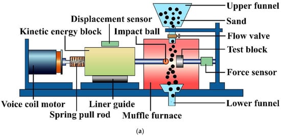
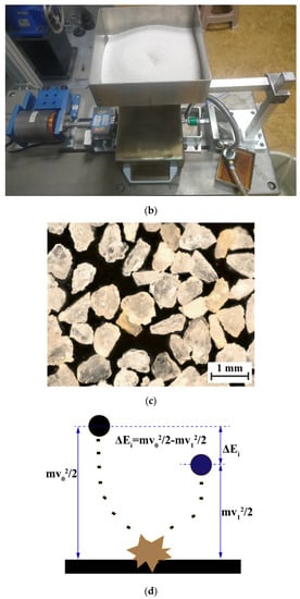
Figure 1.
Schematic of high-temperature impact abrasive wear test equipment: (a) Equipment diagram; (b) physical drawing of equipment; (c) surface topography of sand; (d) energy conversion process.
The samples of this experiment are Cr/W-DLC/DLC multilayer films prepared in Section 2.1. The nano indentation hardness of the films is 22.57 GPa. The impact head adopts silicon nitride ceramic ball with diameter of 4.76 mm (microhardness is 2273 HV). The foreign object adopts natural quartz sand (ω SiO2 > 98%), then the particle size is 380 μm (about 40 mesh) after manual crushing and screening. Figure 1c shows an optical microscope image of quartz sand particles view of quartz sand particles. The variables of the experiment are the temperature and the presence or absence of sand particles. The test temperature is selected as room temperature (RT), 100 °C, 300 °C, and 500 °C. The kinetic energy block mass is 150 g. The impact velocity is 100 mm/s, impact distance is 8 mm, and impact cycle is 104. After the experiment, the size and shape of pits produced by impact wear and the topography of wear surface should be observed.
2.3. Methods of Characterization and Analysis
Raman spectrometer (LabRAM HR Evolution, Horiba, Kyoto, Japan) with an excitation wavelength of 532 nm was used to analyze the composition and structure of the DLC film [25,26,27]. The main recorded characteristic wave number range was 500–2000 cm−1, and the laser power is set to 50% of the total capacity. The composition analysis of the films was evaluated by X-ray diffraction (XRD, Bruker-axs D8 Advance) with Cu kα radiation of a wavelength of 0.15 nm. The scanning range was 20–80° with a step of 0.06, and the operating voltage was 40 kV. The hardness and elastic modulus of the films were measured by nano-indentation apparatus (the model is UK MML NanoTest Vantage). The indenter adopts Berkovich triangular pyramid indenter, Young’s modulus of the indenter is 1141 GPa, and the Poisson’s ratio is 0.07. The wear condition of the sample surface was observed by optical microscope (VHX-1000C), and the micro-topography of the wear surface was observed by JSM6610LV scanning electron microscope (SEM). EDS analyzer (OXFORD X-Max 80) is used to evaluate the distribution of elements on the surface and cross section of the wear scar. The contour GT white light interferometer was used to measure the wear profile, depth, and volume of the multilayer film.
3. Results and Discussion
3.1. Structure and Composition of Cr/W-DLC/DLC Multilayer Films
Figure 2 shows SEM micrographs and EDS analysis results of the surface and cross-section of Cr/W-DLC/DLC multilayers. Figure 2a shows that the structure of the multilayer film is dense and uniform without evident defects. Figure 2b,c show that the Cr transition layer is closely combined with the W-DLC film and substrate. According to the EDS mapping result of the Cr/W-DLC/DLC multilayer film, the element distribution of different layers is obviously different. As shown in Figure 2b, the thickness of the top DLC film is about 2.0 μm, the interlayer W-DLC film is about 1.1 μm, whereas the Cr transition layer is about 0.9 μm.
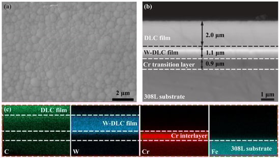
Figure 2.
SEM micrographs and EDS analysis results of the surface and cross-section of Cr/W-DLC/DLC multilayers: (a) Surface topography; (b) cross-sectional topography; (c) EDS mapping of the cross-section.
Figure 3a shows a wide Raman peak between 1000 and 1750 cm−1 in Raman spectra and the wide Raman peaks are fitted as D peak and G peak, which are located at 1375.74 and 1550.45 cm−1, respectively. The intensity ratio of the D peak to the G peak of the Raman spectrum (ID/IG) was 0.70. The D peak is due to the breathing modes of sp2 carbon atoms in rings. The G peak is due to the bond stretching of all pairs of sp2 carbon atoms in the rings and chains [28]. The prepared Cr/W-DLC/DLC multilayer films presented the Raman spectral characteristics of typical amorphous carbon [29,30]. Figure 3b shows the XRD pattern of the prepared multilayer film and 308L substrate. There are mainly diffraction peaks of WC1−X and Cr in the XRD pattern of Cr/W-DLC/DLC multilayer films, indicating the amorphous characteristics of the DLC film. The Cr diffraction peak mainly comes from the transition layer between the films, while the WC1−X diffraction peak comes from the metastable β-WC1−X nanocrystalline component formed in the interlayer W-DLC film [15,31]. The substrate has three diffraction peaks at 2θ = 43.60°, 50.74°, and 74.62°, which indicate γ-(111), γ-(200), and γ-(220) crystal plane, respectively. This means the 308L substrate is composed of a single austenite [32].
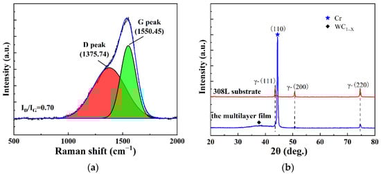
Figure 3.
Raman spectra (a) and XRD pattern (b) of the Cr/W-DLC/DLC multilayer films.
3.2. Dynamic Response Analysis of Interface
Dynamic responses of the specimens deposited Cr/W-DLC/DLC multilayer films during impact at various temperatures are shown in Figure 4a,b. When the impact cycle is 104, the rebound velocity and the peak contact force decrease gradually with the increase in temperature; the rebound velocity decreases from 96.35 mm/s to 87.7 mm/s when the temperature increases from room temperature (RT) to 500 °C. When the impact velocity is constant, the smaller rebound velocity indicates a more significant change in kinetic energy. Thus, more energy is absorbed by the specimen. In the impact process, the energy absorbed by the specimen is mainly used for plastic deformation and removal of materials. The peak contact force decreases from 14.75 N at RT to 10.50 N at 500 °C. This condition may be due to the increase in plastic deformation of the specimens, resulting in an increase in the contact area and a reduction in contact force. Figure 4c,d show the dynamic responses of the specimens at various temperatures under sand conditions. The rebound velocity and the peak contact force also decrease gradually with the increase in temperature. However, the rebound velocity and the peak contact force decrease under sand conditions compared with the absence of sand particles. When the impact cycle is 104, and the temperature is 500 °C, the peak contact force is only 9.6 N under sand conditions, which is 0.97 N less than that under no sand conditions. At the same time, the rebound velocity is only 84.38 mm/s, which is 3.32 mm/s less than that under no sand conditions. This finding may be because of the contact between the impact ball and sand particles during the impact process before impacting the specimens. In this process, the sand absorbs part of the energy and has a certain kinetic energy. Then, the sand particles impact the surface of the specimens before the impact ball.
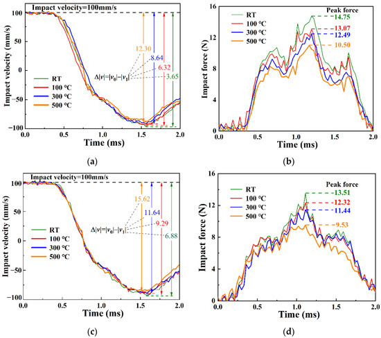
Figure 4.
The impact velocity and force–time diagrams for different experimental conditions (impact cycle is 104): (a) No sand, velocity−time, (b) No sand, contact force−time, (c) sand, velocity−time, (d) sand, contact force−time.
3.3. Analysis of Impact Wear Mechanism
Figure 5 shows the surface topography of Cr/W-DLC/DLC multilayer films without sand. When the impact cycle is 104, the area of impact increase gradually with the temperature rise. The diameter of wear areas increases from 407 μm at RT to 515 μm at 500 °C. This finding may be due to the decrease in substrate hardness (substrate softening) caused by the increase in temperature [33,34]. The surface topography of Cr/W-DLC/DLC multilayer films shows no cracks and coating damage in the wear area. This condition indicates the film has good adhesion properties and thermal stability [35]. At the same time, the considerable increase in temperature did not cause the significant increases in wear area because work hardening occurs on the surface of the wear scars during the impact process, thereby increasing the surface strength and improving the wear resistance [36].
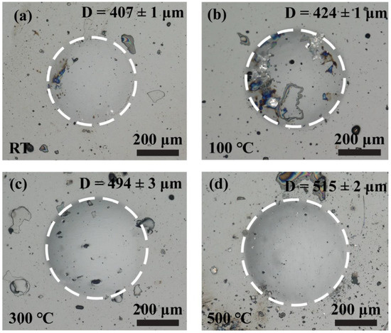
Figure 5.
Surface topography of the surface topography of Cr/W-DLC/DLC multilayer films under no sand condition at (a) RT, (b) 100 °C, (c) 300 °C, and (d) 500 °C.
Figure 6 shows the surface topography of Cr/W-DLC/DLC multilayer films under sand conditions. The area of impact wear scars also increases gradually with the increase in temperature. The diameter of wear areas increases from 1667 μm at RT to 2617 μm at 500 °C. Compared with no sand condition, adding sand particles leads to the intensification of impact wear and an increase in surface roughness because sand particles have many edges and corners and can cut and plow the surface of wear scars [37,38]. At the same time, under the extrusion of the impact ball and the sample, the sand particles are broken and embedded into the wear scars surface during the impact process [39].
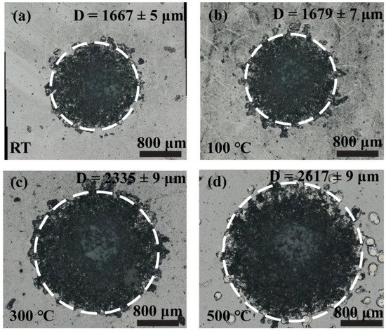
Figure 6.
Surface topography of Cr/W-DLC/DLC multilayer films under the sand condition at (a) RT, (b) 100 °C, (c) 300 °C, and (d) 500 °C.
Figure 7 shows the wear scar profiles of Cr/W-DLC/DLC multilayer films under no sand conditions and sand conditions at various temperatures. Whether under a sand or no-sand condition, the max depth of impact increases gradually with the increase in temperature. The max depth of wear scars is from 4.73 μm at RT to 12.89 μm at 500 °C, indicating an increase of nearly two times. This finding may be due to the softening of the substrate caused by the rise in temperature, resulting in more severe plastic deformation during the impact process [34]. The wear scar profiles of Cr/W-DLC/DLC multilayer films show that the surface of wear scars under sand conditions is rougher than that under no sand conditions. This finding also indicates that adding sand particles aggravates the wear of Cr/W-DLC/DLC multilayer films under the same experimental conditions [40].
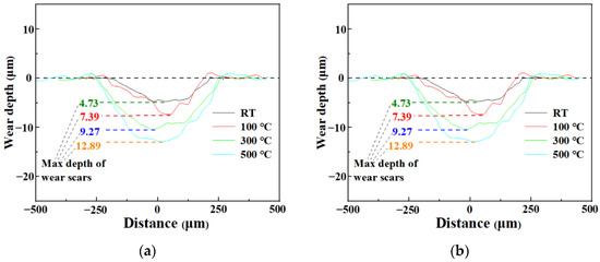
Figure 7.
Wear scar profiles of Cr/W-DLC/DLC multilayer films under (a) no-sand condition and (b) sand condition at various temperatures.
Figure 8 and Figure 9 show the wear scar topography and element distribution of Cr/W-DLC/DLC multilayer films at RT and 500 °C under no sand conditions, respectively. Pits due to plastic deformation are clearly visible at RT or at 500 °C. After the plastic deformation of the 308L substrate, the tensile stress produced by the films may lead to cracks and spalling of films [41]. However, the films are not seriously worn except that the C layer has a slight peeling pit at 500 °C. Figure 8d and Figure 9d show that only C element was detected in EDS mapping data of wear scar surface, confirming the integrity of the Cr/W-DLC/DLC multilayer films. A smooth surface without wear debris can prove that the wear mechanism is plastic deformation at various temperatures under no sand conditions [42].
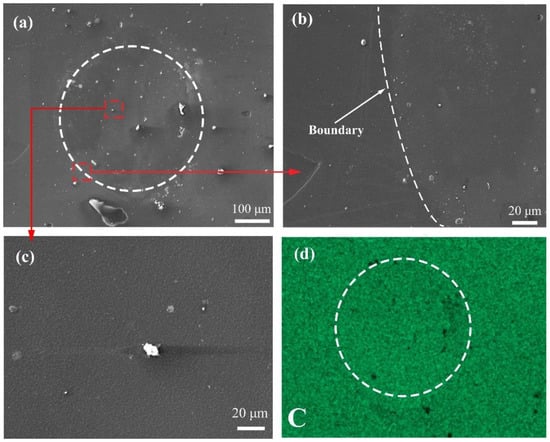
Figure 8.
Wear scar topography and elemental distribution of Cr/W-DLC/DLC multilayer films at RT under no sand condition: (a–c) wear scar topography; (d) elemental distribution.
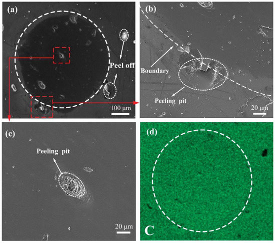
Figure 9.
Wear scar topography and elemental distribution of Cr/W-DLC/DLC multilayer films at 500 °C under no-sand condition: (a–c) wear scar topography; (d) elemental distribution.
Figure 10 and Figure 11 present the wear scar topography and elemental distribution of Cr/W-DLC/DLC multilayer films at RT and 500 °C under sand conditions, respectively. The chemical compositions of points A to F are presented in Table 2. Evident cutting and ploughing tracks are found at wear scar areas at RT or at 500 °C. As shown in Figure 10b and Figure 11b, the film was broken at the wear areas, and delamination and spalling of the film occurred. The significant enrichment of Fe in Figure 10c and Figure 11c show that the substrate is exposed after the coating is damaged. And Fe elements detected from points B and F also prove the damage of the film. The enrichment of Si proves the existence of sand particles in the wear scar area. Si elements are also detected from points A, B, and F in Table 2. Compared with the impact ball, the edges and corners of sand particles may increase the contact stress and damage the films quickly. Compared with RT, the substrate softens at high temperatures and the wear is more severe after the films are broken [39]. The mechanism of impact wear with sand is mainly abrasive wear. Evidently, film spalling also exists in high-temperature and sand particle environments [38]. Figure 12 shows the impact mechanism of Cr/W-DLC/DLC multilayer under no-sand condition and sand condition. Figure 12a shows the schematic of the impact mechanism of Cr/W-DLC/DLC multilayer films under no sand condition. The multilayer film has severe plastic deformation, but the wear scar surface is smooth and the film does not peel off completely. Figure 12b shows the schematic of the impact mechanism of Cr/W-DLC/DLC multilayer films under sand conditions. The embedded sand particles can cut and plough the wear scar area and make the film delaminate and peel off seriously.
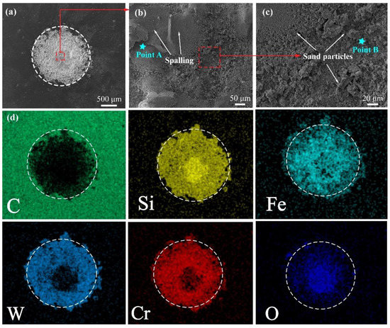
Figure 10.
Wear scar topography and elemental distribution of Cr/W-DLC/DLC multilayer films at RT under the sand condition: (a–c) wear scar topography; (d) elemental distribution.
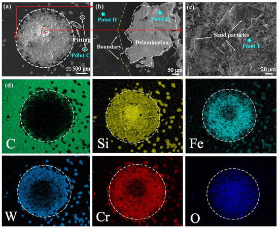
Figure 11.
Wear scar topography and elemental distribution of Cr/W-DLC/DLC multilayer films at 500 °C under the sand condition: (a–c) wear scar topography; (d) elemental distribution.
Table 2.
Chemical composition at typical position of wear scar (wt. %).
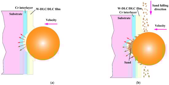
Figure 12.
The impact mechanism of Cr/W-DLC/DLC multilayer under (a) no-sand condition and (b) sand condition.
Figure 13 presents the cross-sectional topography of Cr/W-DLC/DLC multilayer films at 500 °C under sand conditions and no-sand conditions. The chemical compositions of points A to F are presented in Table 3. Under the no-sand condition, the film and substrate have evident plastic deformation. Still, the integrity of the film is good, as shown in Figure 13a. Evident plowing track and the rough surface can be observed at 500 °C under sand conditions. The EDS of Cr/W-DLC/DLC multilayer films in Figure 13b proved the existence of sand particles. And Si elements were also detected at points B and C in Table 3. Sand particles are embedded in the surface of wear scars, and the surface is cut and plowed, resulting in more severe wear. More energy is absorbed for plastic deformation and material removal under sand conditions. As a result, the rebound velocity and peak contact force become lower than that under no-sand conditions. The temperature leads to the softening of the substrate; thus, the specimens become more prone to plastic deformation and material removal.
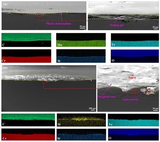
Figure 13.
Cross-sectional topography of Cr/W-DLC/DLC multilayer films at 500 °C under (a) no-sand condition and (b) sand condition.
Table 3.
Chemical composition at typical position of wear scar (wt. %).
4. Conclusions
The Cr/W-DLC/DLC multilayer films were deposited by magnetron sputtering. The prepared multilayer film has a dense and uniform structure without evident defects, and the Cr interlayer is closely combined with the W-DLC film and substrate. The impact and wear properties of Cr/W-DLC/DLC multilayer films were performed at different temperatures under sand and no-sand conditions. The following conclusions were drawn:
- The Cr/W-DLC/DLC multilayer films have excellent impact wear resistance and favorable adhesion with the substrate at different temperatures under no-sand conditions. The mechanism of impact wear without sand is mainly plastic deformation.
- Sand particles have strong destructive effect on the surface of Cr/W-DLC/DLC multilayer films and have a clear cutting and ploughing effect on the wear scar areas. The mechanism of impact wear with sand is mainly abrasive wear.
- The rebound velocity and the peak contact force under sand conditions are lower than under no-sand conditions at the same temperature. This finding indicates that more energy is absorbed for plastic deformation and material removal under sand conditions.
Author Contributions
Study design, W.Z.; data collection, W.Z. and H.W.; date analysis, W.Z.; writing—original draft preparation, W.Z.; writing—review and editing, H.W. and L.M.; Figures—drawing and editing, H.W. and L.M.; literature research and formal analysis, C.Z. All authors have read and agreed to the published version of the manuscript.
Funding
The authors are grateful for the financial support from Sichuan Youth Science and Technology Planning Project (Grant No.23NSFSC6400), and Key R & D science and technology plan project of Luzhou City, Sichuan Province, of China (Grant No. 2020-GYF-1), Chunhui Project from Education Ministry of China (Grant No. 192644) and the Sichuan Science and Technology Planning Project (Grant No. 2022JDJQ0019).
Data Availability Statement
Not applicable.
Acknowledgments
The authors would like to express their gratitude for the support of the Institute of Tribology of Southwest Jiaotong University.
Conflicts of Interest
The authors declare no conflict of interest.
References
- Cai, Z.B.; Li, Z.Y.; Yin, M.G.; Zhu, M.H.; Zhou, Z.R. A review of fretting study on nuclear power equipment. Tribol. Int. 2020, 144, 106095. [Google Scholar] [CrossRef]
- Chen, Y.X.; Gong, W.J.; Kang, R. Review and propositions for the sliding/impact wear behavior in a contact interface. Chin. J. Aeronaut. 2020, 33, 391–406. [Google Scholar] [CrossRef]
- Kopec, M.; Pata, O.; Malá, M.; Halodová, P.; Krejcí, J. On debris-fretting impact—The study of oxide and chromium layer application. J. Nucl. Eng. Radiat. Sci. 2020, 7, 021802. [Google Scholar] [CrossRef]
- Nicholls, J.R.; Jaslier, Y.; Rickerby, D.S. Erosion and foreign object damage of thermal barrier coating. Mater. Sci. 1997, 251–254, 935–948. [Google Scholar]
- Robertson, J. Diamond-like Amorphous Carbon. Mater. Sci. Eng. R Rep. 2002, 37, 129–281. [Google Scholar] [CrossRef]
- Scharf, T.W.; Singer, I.L. Tribology of Diamond-Like Carbon Films: Fundamentals and Applications; Springer: New York, NY, USA, 2008; pp. 201–236. [Google Scholar]
- Zeng, Q.; Eryilmaz, O.; Erdemir, A. Analysis of Plastic Deformation in Diamond Like Carbon Films-Steel Substrate System with Tribological Tests. Thin Solid Films 2011, 519, 3203–3212. [Google Scholar] [CrossRef]
- Zeng, Q.; Yu, F.; Dong, G. Super lubricity behaviors of Si3N4/DLC films under PAO oil with nano boron nitride additive lubrication. Surf. Interface Anal. 2013, 45, 1283–1290. [Google Scholar] [CrossRef]
- Konca, E.; Cheng, Y.T.; Weiner, A.M.; Dasch, J.M.; Alpas, A.T. Elevated temperature tribological behavior of non-hydrogenated diamond-like carbon coatings against 319 aluminum alloy. Surf. Coat. Technol. 2006, 200, 3996–4005. [Google Scholar] [CrossRef]
- Bhowmick, S.; Khan, M.Z.U.; Banerji, A.; Lukitsch, M.J.; Alpas, A.T. Low friction and wear behaviour of non-hydrogenated DLC (a-C) sliding against fluorinated tetrahedral amorphous carbon (ta-C-F) at elevated temperatures. Appl. Surf. Sci. 2018, 450, 274–283. [Google Scholar] [CrossRef]
- Zeng, Q.; Eryilmaz, O.; Dong, G.; Luo, L. Thermodynamics and friction mechanism analysis of DLC films on H13 steel under high Temperature. In Proceedings of the 5th World Tribology Congress, Torino, Italy, 8–13 September 2013. [Google Scholar]
- Aouadi, S.M.; Gao, H.; Martini, A.; Scharf, T.W.; Muratore, C. Lubricious oxide coatings for extreme temperature applications: A review. Surf. Coat. Technol. 2014, 257, 266–277. [Google Scholar] [CrossRef]
- Zeng, Q.F.; Ali, E.; Osman, E. Ultralow friction of ZrO2 ball sliding against DLC films under various environments. Appl. Sci. 2017, 7, 938. [Google Scholar] [CrossRef]
- Bhowmick, S.; Lou, M.; Khan, M.; Banerji, A.; Alpas, A.T. Role of an oxygen atmosphere in high temperature sliding behaviour of W containing diamond-like carbon (W-DLC). Surf. Coat. Technol. 2017, 332, 399–407. [Google Scholar] [CrossRef]
- Gu, K.; Zheng, Y.; Luo, J.; Qin, X.; Yang, X.; Abbas, N.; Tang, J.N. Microstructure, mechanical and tribological properties of DLC/Cu-DLC/W-DLC composite films on SUS304 stainless steel substrates. Mater. Res. Express 2019, 6, 086406. [Google Scholar] [CrossRef]
- Li, Q.; Gao, K.X.; Zhang, L.F.; Wang, J.; Zhang, B.; Zhang, J.Y. Further improving the mechanical and tribological properties of low content Ti-doped DLC film by W incorporating. Appl. Surf. Sci. 2015, 353, 522–529. [Google Scholar]
- Gharam, A.A.; Lukitsch, M.J.; Balogh, M.P.; Irish, N.; Alpas, A.T. High temperature tribological behavior of W-DLC against aluminum. Surf. Coat. Technol. 2011, 206, 1905–1912. [Google Scholar] [CrossRef]
- Banerji, A.; Bhowmick, S.; Alpas, A.T. High temperature tribological behavior of W containing diamond-like carbon (DLC) coating against titanium alloys. Surf. Coat. Technol. 2014, 241, 93–104. [Google Scholar] [CrossRef]
- Zhan, H.; Wang, R.; Li, Z.; Xu, T.; Wang, W. Effects of fragments on W-DLC films properties under boundary lubrication condition in the friction system. China Weld. 2018, 27, 31–38. [Google Scholar]
- Wei, X.U.; Dai, M.; Lin, S.; Hou, H.; Li, H.; Zhou, K. High Temperature Tribological Behavior of W-Doped Diamond-like Carbon Films. Tribology 2017, 37, 379–386. [Google Scholar]
- Ye, T.; Ma, J.W.; Jia, Z.Y.; Li, T.L.; Liu, W.; Yu, W.J. Microstructure, mechanical properties and low-temperature tribological behavior of Cr/Cr-W/W-DLC/DLC multilayer coatings on 5A06 Al alloy. J. Mater. Res. Technol. 2022, 18, 810–819. [Google Scholar] [CrossRef]
- Duminica, F.D.; Belchi, R.; Libralesso, L.; Mercier, D. Investigation of Cr(N)/DLC multilayer coatings elaborated by PVD for high wear resistance and low friction applications. Surf. Coat. Technol. 2018, 337, 396–403. [Google Scholar] [CrossRef]
- Du, J.; Hao, T.M.; Zhang, X.; Su, G.S.; Zhang, P.R.; Sun, Y.J.; Zhang, J.J.; Xu, C.H. Finite element investigation of cutting performance of Cr/W-DLC/DLC composite coated cutting tool. Int. J. Adv. Manuf. Technol. 2022, 118, 2177–2192. [Google Scholar] [CrossRef]
- Gayathri, S.; Kumar, N.; Krishnan, R.; Ravindran, T.R.; Dash, S.; Tyagi, A.K.; Raj, B.; Sridharan, M. Tribological properties of pulsed laser deposited DLC/TM (TM = Cr, Ag, Ti and Ni) multilayers. Tribol. Int. 2012, 53, 87–97. [Google Scholar] [CrossRef]
- Cui, X.J.; Ning, C.M.; Shang, L.L.; Zhang, G.A.; Liu, X.Q. Structure and anticorrosion, friction, and wear characteristics of pure diamond-like carbon (DLC), Cr-DLC, and Cr-H-DLC films on AZ91D Mg alloy. J. Mater. Eng. Perform. 2019, 28, 1213–1225. [Google Scholar] [CrossRef]
- Elhadji, C.T.B.; Marcello, R.D.; Paulo, S.M.; Bárbara, D.S.P.; Matheus, P.M.D.C.; Jorge, W.B. Deconvolution process approach in Raman spectra of DLC coating to determine the sp3 hybridization content using the ID/IG ratio in relation to the quantification determined by X-ray photoelectron spectroscopy. Diam. Relat. Mater. 2022, 122, 108818. [Google Scholar]
- Feng, X.G.; Hu, H.J.; Gui, B.H.; Guo, F.J.; Wang, K.L.; Zheng, Y.G.; Zhou, H. Corrosion behavior of W-DLC and DLC films deposited on plasma nitrided CF170 steel in H2SO4 solution. Vacuum 2022, 204, 111385. [Google Scholar] [CrossRef]
- Casiraghi, C.; Piazza, F.; Ferrari, A.C.; Grambole, D.; Robertson, J. Bonding in hydrogenated diamond-like carbon by Raman spectroscopy. Diam. Relat. Mater. 2005, 14, 1098–1102. [Google Scholar] [CrossRef]
- Takizawa, K.; Kunitsugu, S. The relationship between characteristics of DLC film and electron temperature measured by optical emission spectroscopy. IEEE Trans. Plasma Sci. 2016, 44, 3207–3213. [Google Scholar] [CrossRef]
- Santiago, J.A.; Fernández-Martínez, I.; Kozák, T.; Capek, J.; Wennberg, A.; Molina-Aldareguia, J.M.; Bellido-González, V.; González-Arrabal, R.; Monclus, M.A. The influence of positive pulses on HiPIMS deposition of hard DLC coatings. Surf. Coat. Technol. 2019, 358, 43–49. [Google Scholar] [CrossRef]
- Umretiya, R.V.; Elward, B.; Lee, D.; Anderson, M.; Rojas, J.V. Mechanical and chemical properties of PVD and cold spray Cr-coatings on Zircaloy-4. J. Nucl. Mater. 2020, 541, 152420. [Google Scholar] [CrossRef]
- Li, M.; Lu, T.; Dai, J.W.; Jia, X.J.; Gu, X.H.; Dai, T. Microstructure and mechanical properties of 308L stainless steel fabricated by laminar plasma additive manufacturing. Mater. Sci. Eng. 2020, 770, 138523. [Google Scholar] [CrossRef]
- Bremond, F.; Fournier, P.; Platon, F. Test temperature effect on the tribological behavior of DLC-coated 100C6-steel couples in dry friction. Wear 2003, 254, 774–783. [Google Scholar] [CrossRef]
- Chen, X.-D.; Wang, L.-W.; Yang, L.-Y.; Tang, R.; Yu, Y.-Q.; Cai, Z.-B. Investigation on the impact wear behavior of 2.25Cr–1Mo steel at elevated temperature. Wear 2021, 476, 203740. [Google Scholar] [CrossRef]
- Liu, B.; Li, W.; Lu, X.; Jia, X.; Jin, X. The effect of retained austenite stability on impact-abrasion wear resistance in carbide-free bainitic steels. Wear 2019, 428, 127–136. [Google Scholar] [CrossRef]
- Rastegar, V.; Karimi, A. Surface and subsurface deformation of wear resistant steels exposed to impact wear. J. Mater. Eng. Perform. 2014, 23, 927–936. [Google Scholar] [CrossRef]
- Nguyen, Q.B.; Nguyen, V.B.; Lim, C.Y.H.; Trinh, Q.T.; Sankaranarayanan, S.; Zhang, Y.W.; Gupta, M. Effect of impact angle and testing time on erosion of stainless steel at higher velocities. Wear 2014, 321, 87–93. [Google Scholar] [CrossRef]
- Peng, S.G.; Song, R.B.; Sun, T.; Yang, F.Q.; Deng, P.; Wu, C.J. Surface failure behavior of 70 Mn martensite steel under abrasive impact wear. Wear 2016, 362–363, 129–134. [Google Scholar] [CrossRef]
- Desale, G.R.; Gandhi, B.K.; Jain, S.C. Effect of erodent properties on erosion wear of ductile type materials. Wear 2006, 261, 914–921. [Google Scholar] [CrossRef]
- Wu, S.B.; Cai, Z.B.; Lin, Y.; Li, Z.Y.; Zhu, M.H. Effect of abrasive particle hardness on interface response and impact wear behavior of TC17 titanium alloy. Mater. Res. Express 2019, 6, 016521. [Google Scholar] [CrossRef]
- Li, H.; Maziar, R.; Li, M.; Ma, C.; Wang, J. Tribological performance of selective laser melted 316L stainless steel. Tribol. Int. 2018, 128, 121–129. [Google Scholar] [CrossRef]
- Yu, T.D.; Fu, G.Z.; Yu, Y.Q.; Zhu, L.T.; Liu, M.F.; Li, W.; Deng, Q.; Cai, Z.B. Wear Characteristics of the Nuclear Control Rod Drive Mechanism (CRDM) Movable Latch Serviced in High Temperature Water. Chin. J. Mech. Eng. 2022, 35, 26. [Google Scholar] [CrossRef]


Publisher’s Note: MDPI stays neutral with regard to jurisdictional claims in published maps and institutional affiliations. |
© 2022 by the authors. Licensee MDPI, Basel, Switzerland. This article is an open access article distributed under the terms and conditions of the Creative Commons Attribution (CC BY) license (https://creativecommons.org/licenses/by/4.0/).