
Welding Properties of Dissimilar Al-Cu Thin Plate by a Single-Mode Fiber Laser


Abstract
1. Introduction
2. Materials and Methods
2.1. Materials
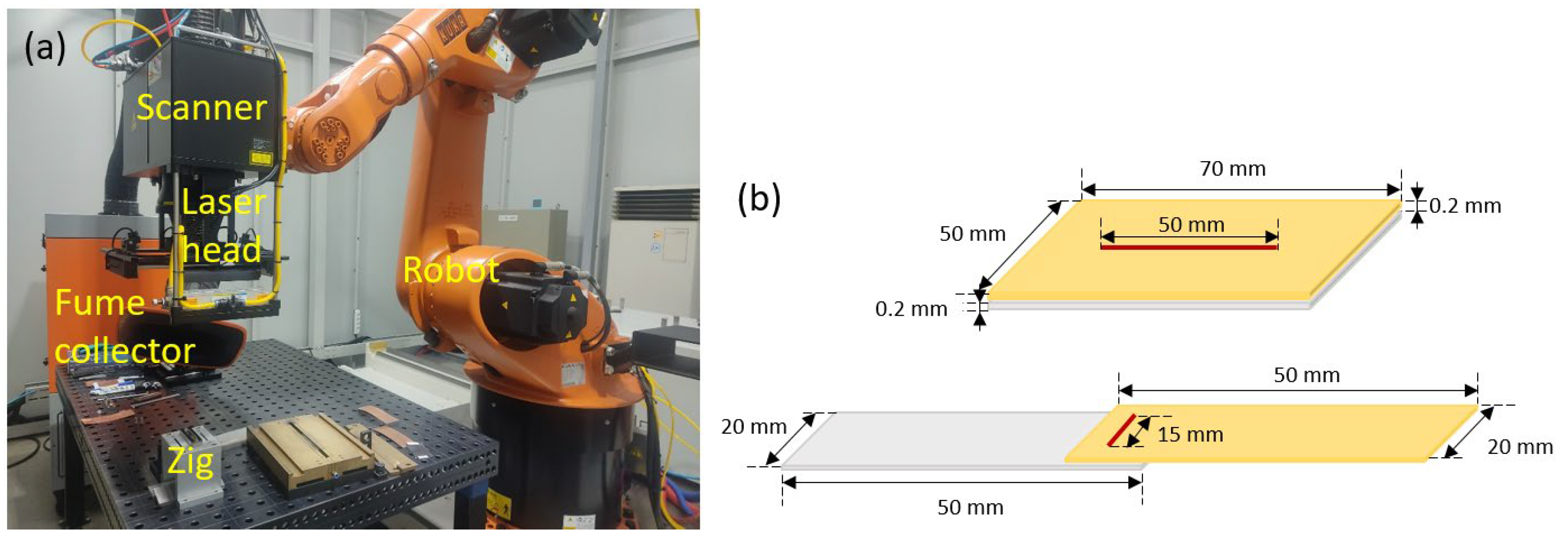
2.2. Laser Welding
3. Results
3.1. Cross-Sectional Analysis
3.1.1. Macro Analysis
3.1.2. Composition Analysis
3.2. Strength
3.2.1. Tensile Shear Strength
3.2.2. Fracture Morphology
4. Discussion
4.1. Molten Pool
4.2. IMC
5. Conclusions
- (1)
- When bonding was performed while increasing the speed at the same output of 2 kW, the amount of heat input decreased, and when the speed reached 1000 mm/s, the bonding was not performed with a certain base metal on the top.
- (2)
- Pores were observed according to the experimental conditions, and when the amount of heat input was large, they were generated inside the Al or adjacent to the Cu mixed zone, and the pores were generated between the unmelted Cu in the Al molten layer. When the laser was irradiated to Al at a speed of 400 mm/s, a cross section without pores was obtained.
- (3)
- As a result of EDS mapping analysis, it was confirmed that Cu was distributed in a very small amount when Al was on the top, which is thought to be due to fume. When Cu was on the top and full penetration was achieved to the Al on the bottom, it was confirmed that Cu existed along the bottom surface, and the recoil pressure inside the keyhole exerted downward influence.
- (4)
- As a result of EDS analysis, it was confirmed that CuAl2 was spread inside the Al and Cu phases or existed between the two phases in the form of a layer inside the weld.
- (5)
- As a result of the tensile shear strength test, fracture occurred on the Cu side at the speed of 800 mm/s when Al was on the top of the joint, and when Cu was on the top. Specimens fractured in the Al base metal were fractured in the softened area inside the heat-affected zone, not the molten area, and fractures occurred in the area where Cu was melted and IMC was generated inside.
Author Contributions
Funding
Institutional Review Board Statement
Informed Consent Statement
Data Availability Statement
Acknowledgments
Conflicts of Interest
References
- Lee, S.-J.; Choi, K.-D.; Park, B.-H.; Kim, J.-D.; Suh, J. Weldability of aluminum alloys laser welding for with high-power disk laser. J. Korean Soc. Mar. Eng. 2017, 41, 638–645. [Google Scholar]
- Kang, M.J.; Choi, W.S.; Kang, S.H. Ultrasonic and Laser Welding Technologies on Al/Cu Dissimilar Materials for the Lithium-Ion Battery Cell or Module Manufacturing. J. Weld. Join. 2019, 37, 52–59. [Google Scholar] [CrossRef]
- Lee, S.-J.; Kim, J.-D.; Katayama, S. A Study on the Characteristic of Weld Joint and Tensile Fracture of SUS304 and Cu High-Speed Dissimilar Lap Welds by Single Mode Fiber Laser. J. Weld. Join. 2014, 32, 56–63. [Google Scholar] [CrossRef][Green Version]
- Dimatteo, V.; Ascari, A.; Fortunato, A. Continuous laser welding with spatial beam oscillation of dissimilar thin sheet materials (Al-Cu and Cu-Al): Process optimization and characterization. J. Manuf. Process. 2019, 44, 158–165. [Google Scholar] [CrossRef]
- Knaak, C.; von Eßen, J.; Kröger, M.; Schulze, F.; Abels, P.; Gillner, A. A Spatio-Temporal Ensemble Deep Learning Architecture for Real-Time Defect Detection during Laser Welding on Low Power Embedded Computing Boards. Sensors 2021, 21, 4205. [Google Scholar] [CrossRef]
- Firouzdor, V.; Kou, S. Al-to-Cu Friction Stir Lap Welding. Metall. Mater. Trans. A 2012, 43, 303–315. [Google Scholar] [CrossRef]
- Lee, S.J.; Nakamura, H.; Kawahito, Y.; Katayama, S. Effect of welding speed on microstructural and mechanical properties of laser lap weld joints in dissimilar Al and Cu sheets. Sci. Tech. Weld. Join. 2014, 19, 111–118. [Google Scholar] [CrossRef]
- Lee, S.-J.; Takahashi, M.; Kawahito, Y.; Katayama, S. Microstructural Evolution and Characteristics of Weld Fusion Zone in High Speed Dissimilar Welding of Ti and Al. Int. J. Precis. Eng. Manuf. 2015, 16, 2121–2127. [Google Scholar] [CrossRef]
- Lee, S.-J.; Katayama, S.; Kim, J.-D. Microstructural behavior on weld fusion zone of Al-Ti and Ti-Al dissimilar lap welding using single-mode fiber laser. J. Korean Soc. Mar. Eng. 2014, 38, 133–139. [Google Scholar] [CrossRef]
- Zhang, Y.; Gao, X.; You, D.; Jiang, X.; Ge, W. Investigation of Laser Butt Welding of AISI 304L and Q235 Steels Based on Numerical and Experimental Analyses. Metals 2022, 12, 803. [Google Scholar] [CrossRef]
- Zhou, H.; Fu, F.; Dai, Z.; Qiao, Y.; Chen, J.; Liu, W. Effect of Laser Power on Microstructure and Micro-Galvanic Corrosion Behavior of a 6061-T6 Aluminum Alloy Welding Joints. Metals 2021, 11, 3. [Google Scholar] [CrossRef]
- Lee, S.J.; Sharma, A.; Jung, D.H.; Jung, J.P. Influence of Arc Brazing Parameters on Microstructure and Joint Properties of Electro-Galvanized Steel. Metals 2019, 9, 1006. [Google Scholar] [CrossRef]
- Lee., S.-J.; Katayama, S.; Kawahito, Y.; Kim, J.-D.; Suh, J. Weld Plume Behavior during Laser Lap Welding of Al and Ti Dissimilar sheets. In Proceedings of the 35th International Congress on Applications of Lasers & Electro-Optics (ICALEO® 2016), San Diego, CA, USA, 16–20 October 2016; p. 407. [Google Scholar]
- Wang, L.; Zhang, G.; Xu, J.; Li, Y.; Chen, Q.; Rong, Y.; Huang, Y. Effect of Welding Parameters on the Geometry, Microstructure, and Corrosion Resistance of Laser Welded 16 mm EH40 Joints. Metall. Mat. Trans. B 2021, 52, 3930–3937. [Google Scholar] [CrossRef]
- Kim, J.; Kim, Y.; Kim, J.; Kim, Y.; Kim, D.; Kang, S.; Pyo, C. A Study on Lap Joint Welding of Thin Plate ASTM F1684 Using Fiber Laser Welding. Processes 2021, 9, 428. [Google Scholar] [CrossRef]
- Oh, R.; Kim, D.Y.; Ceglarek, D. The Effects of Laser Welding Direction on Joint Quality for Non-Uniform Part-to-Part Gaps. Metals 2016, 6, 184. [Google Scholar] [CrossRef]
- Arya, H.; Singh, K.; Singh, S. Cooling Rate Effect on Microhardness for SAW Welded Mild Steel Plate. Int. J. Theo. Appl. Res. Mech. Eng. 2013, 2, 71–77. [Google Scholar]
- Zhao, H.; Qi, H. Numerical Simulation of Transport Phenomena for Laser Full Penetration Welding. J. Weld. Join. 2017, 35, 13–22. [Google Scholar] [CrossRef]
- Ferro, P.; Bonollo, F.; Tiziani, A. Laser welding of copper–nickel alloys: A numerical and experimental analysis. Sci. Tech. Weld. Join. 2005, 10, 300–310. [Google Scholar] [CrossRef]
- Katayama, S.; Kawahito, Y.; Mizutani, M. Elucidation of laser welding phenomena and factors affecting weld penetration and welding defects. Phys. Procedia 2010, 5, 9–17. [Google Scholar] [CrossRef]
- Wang, C.; Wang, C.; Gao, X.; Tian, M.; Zhang, Y. Research on Microstructure Characteristics of Welded Joint by Magneto-Optical Imaging Method. Metals 2022, 12, 258. [Google Scholar] [CrossRef]
- Sadeghian, A.; Iqbal, N. Blue laser welding of low thickness Ni-coated copper and mild steel for electric vehicle (EV) battery manufacturing. Opt. Laser Tech. 2022, 155, 108415. [Google Scholar] [CrossRef]
- Mathivanan, K.; Plapper, P. Laser welding of dissimilar copper and aluminum sheets by shaping the laser pulses. Procedia Manuf. 2019, 36, 154–162. [Google Scholar] [CrossRef]
- Dimatteo, V.; Ascari, A.; Fortunato, A. Dissimilar laser welding of copper and aluminum alloys in multilayer configuration for battery applications. J. Laser Appl. 2021, 33, 042028. [Google Scholar] [CrossRef]
- Lei, Z.; Zhang, X.; Liu, J.; Li, P. Interfacial microstructure and reaction mechanism with various weld fillers on laser welding-brazing of Al/Cu lap joint. J. Manuf. Process. 2021, 67, 226–240. [Google Scholar] [CrossRef]
- Mohan, D.G.; Tomków, J.; Karganroudi, S.S. Laser Welding of UNS S33207 Hyper-Duplex Stainless Steel to 6061 Aluminum Alloy Using High Entropy Alloy as a Filler Material. Appl. Sci. 2022, 12, 2849. [Google Scholar] [CrossRef]
- Fabbro, R. Depth Dependence and Keyhole Stability at Threshold, for Different Laser Welding Regimes. Appl. Sci. 2020, 10, 1487. [Google Scholar] [CrossRef]
- Fabbro, R. Keyhole modeling during laser welding. J. Appl. Phys. 2000, 87, 4075–4083. [Google Scholar] [CrossRef]
- Fabbro, R. Melt pool and keyhole behavior analysis for deep penetration laser welding. J. Phys. D Appl. Phys. 2010, 43, 445501. [Google Scholar] [CrossRef]


| Property | Al | Cu |
|---|---|---|
| Melting Point (°C) | 660 | 1085 |
| Density (g/cm3) | 2.7 | 8.89 |
| Thermal Conductivity (W/mK) | 234 | 388 |
| Resistance (Ω mm2/m) × 102 | 2.66 | 1.68 |
| Tensile Strength (N/mm2) | 91.5 | 220.5 |
| Hardness (HV) | 57.98 | 106.90 |
| Elongation (%) | 30.10 | 36.67 |
| Parameter | Upper Material | Welding Speed (mm/s) |
|---|---|---|
| 1 | Al | 200 |
| 2 | Al | 400 |
| 3 | Al | 600 |
| 4 | Al | 800 |
| 5 | Al | 1000 |
| 6 | Cu | 200 |
| 7 | Cu | 400 |
| 8 | Cu | 600 |
| 9 | Cu | 800 |
| 10 | Cu | 1000 |
| Parameter | Force (N) | Fracture Area | ||||
|---|---|---|---|---|---|---|
| No. | Upside | Speed (mm/s) | Min | Max | Average | |
| 1 | Al | 200 | 125.8 | 148.0 | 138.0 | Al |
| 2 | Al | 400 | 118.2 | 152.1 | 137.3 | Al |
| 3 | Al | 600 | 129.9 | 149.9 | 142.0 | Al |
| 4 | Al | 800 | 143.6 | 131.7 | 137.7 | Joint |
| 5 | Al | 1000 | - | - | - | - |
| 6 | Cu | 200 | 126.4 | 133.8 | 132.8 | Al |
| 7 | Cu | 400 | 144.4 | 144.2 | 151.8 | Al |
| 8 | Cu | 600 | 150.0 | 138.6 | 148.1 | Al |
| 9 | Cu | 800 | 153.8 | 142.8 | 154.4 | Cu |
| 10 | Cu | 1000 | - | - | - | - |
| Atomic% | Al | Cu | C | O | Phase |
|---|---|---|---|---|---|
| 1 (Al-Cu) | 72.21 | 6.63 | 20.16 | 1.00 | α-Al + CuAl2 |
| 2 | 73.08 | 5.76 | 20.16 | 1.00 | α-Al + CuAl2 |
| 3 | 48.61 | 24.26 | 25.91 | 1.22 | CuAl2 |
| 4 | 15.61 | 49.06 | 34.15 | 1.18 | α-Cu + CuAl2 |
| 1 (Cu-Al) | 20.83 | 46.82 | 32.35 | - | α-Cu + CuAl2 |
| 2 | 75.73 | 3.01 | 18.91 | 2.35 | α-Al + CuAl2 |
| 3 | 17.30 | 49.40 | 32.13 | 1.17 | α-Cu + CuAl2 |
| 4 | 20.57 | 47.16 | 32.27 | - | α-Cu + CuAl2 |
| 5 | 56.98 | 13.82 | 27.83 | 1.37 | α-Al + CuAl2 |
Publisher’s Note: MDPI stays neutral with regard to jurisdictional claims in published maps and institutional affiliations. |
© 2022 by the authors. Licensee MDPI, Basel, Switzerland. This article is an open access article distributed under the terms and conditions of the Creative Commons Attribution (CC BY) license (https://creativecommons.org/licenses/by/4.0/).
Share and Cite
Lee, S.-J.; Choi, K.-D.; Lee, S.-J.; Shin, D.-S.; Jung, J.-P. Welding Properties of Dissimilar Al-Cu Thin Plate by a Single-Mode Fiber Laser. Metals 2022, 12, 1957. https://doi.org/10.3390/met12111957
Lee S-J, Choi K-D, Lee S-J, Shin D-S, Jung J-P. Welding Properties of Dissimilar Al-Cu Thin Plate by a Single-Mode Fiber Laser. Metals. 2022; 12(11):1957. https://doi.org/10.3390/met12111957
Chicago/Turabian StyleLee, Soon-Jae, Kwang-Deok Choi, Su-Jin Lee, Dong-Sik Shin, and Jae-Pil Jung. 2022. "Welding Properties of Dissimilar Al-Cu Thin Plate by a Single-Mode Fiber Laser" Metals 12, no. 11: 1957. https://doi.org/10.3390/met12111957
APA StyleLee, S.-J., Choi, K.-D., Lee, S.-J., Shin, D.-S., & Jung, J.-P. (2022). Welding Properties of Dissimilar Al-Cu Thin Plate by a Single-Mode Fiber Laser. Metals, 12(11), 1957. https://doi.org/10.3390/met12111957