Article

High-Pressure Cold Spray Coatings for Aircraft Brakes Application

by
Marco Granata
1,
Giovanna Gautier di Confiengo
2 and
Francesco Bellucci
1,*
1
Centro Regionale di Competenza, CRdC Tecnologie Scarl, Via Nuova Agnano 11, 80125 Napoli, Italy
2
Institute of Sciences and Technologies for Sustainable Energy and Mobility, National Council of Research, Strada delle Cacce 73, 10135 Torino, Italy
*
Author to whom correspondence should be addressed.
Metals 2022, 12(10), 1558; https://doi.org/10.3390/met12101558
Submission received: 23 June 2022 / Revised: 8 September 2022 / Accepted: 15 September 2022 / Published: 20 September 2022
(This article belongs to the Special Issue Surface Modification Technology in Metals)

Abstract

:
This paper addresses the potential use of high-pressure cold spray (HP-CS) technology to produce a film of friction material onto a low-carbon steel substrate to allow its use as potential composite material for the stators and rotors of aircraft brake units. Namely, WC-Cr3C2-Ni, WC-Ni, WC-Co-Cr, Cr3C2-NiCr and WC-Co coatings were deposited by using HP-CS, for the purpose of creating high friction and wear resistance composite coatings onto a low-carbon steel substrate. Tribological (friction coefficient and wear rate) and thermal properties as well as coating hardness and adhesion to the low-carbon steel substrate were evaluated to assess the potential use of the coatings as brake surface materials. The tribological and adhesion properties were evaluated by using a pin-on-disk high-temperature tribometer at 450 °C and a scratch test, respectively, whereas coatings hardness was evaluated with a Rockwell C hardness tester. Results obtained show that all coatings exhibit high friction coefficients and low wear rates compared to the low-carbon steel substrate, good adhesion, and elevated microhardness. Furthermore, the WC-Co coating shows better microhardness and thermal properties, while the WC-Co-Cr coating exhibited a better friction coefficient. Unfortunately, it was not possible to quantify the wear resistance due to the elevated roughness of the coatings, but from the analysis carried out on the alumina counterpart of the tribometer, it can be concluded that all the coatings exhibited a very low wear rate. In fact, after the tribological tests, it emerged that the alumina counterpart was more abraded than the investigated coatings.

1. Introduction

It is well known that aircraft brakes are a key component for both landing and taking off safely under different and/or critical environmental conditions. The brake consists of a series of discs; the steel stators (which are the stationary units) and the rotors that form the rotating part.
The materials currently used to make aircraft brakes are steel, ceramic matrix, metal matrix composite (MMC) and carbon composites [1,2]. This type of material represents a real innovation in the technical-scientific field. Brakes made in carbon fibre materials are used almost only in competitions, as they require high temperatures to generate braking force. The choice of carbon fibres is due to the properties of these materials whose friction coefficient increases with an increasing temperature which means it brakes better when it is hot [3]. In the latter case, braking takes place by “fusion” of the pads to the disc whose junction pieces are literally torn off during braking. Carbon brakes are made with carbon in the form of fibres (not graphitized) and immersed in a graphite matrix. Furthermore, this material is very light, obtaining excellent specific properties. On the other hand, carbon brakes present very high production and design costs as well as a low static friction coefficient that makes parking performance not optimal.
To reduce the costs related to brake production without significantly altering the braking performance the innovative solution proposed is to use rotor and stator discs made in steel both equipped with a coating (e.g., 0.5 mm) of a suitable friction material. In this way, the main brake material is steel covered with a noble coating.
Several coatings have been developed over time to prevent wear and corrosion issues, and some of them have even been taken into consideration for automobile brake disc applications [4].
The ideal coating material for the best braking action should exhibit high tribological properties, specifically high friction coefficient and high wear resistance, high thermal properties, in particular high thermal conductivity and diffusivity, good adhesion to the substrate, compact microstructures and low porosity inside the coating. In addition to the requirements reported above the coating should be very light to reduce the total weight of the vehicle, and the design and production should be low cost.
HP-CS is a solid-state material deposition technique [5], where micron-sized particles of a powder bond to a substrate because of the high-velocity impact and the associated severe plastic deformation. Acceleration of particles to high velocities is obtained via the expansion of a pressurised and hot gas through a diverging-converging nozzle. Despite heating the process gas, which is to provide higher acceleration of the gas and to facilitate particle deformation through thermal softening, the feedstock remains in the solid state throughout the entire process; hence the name ‘cold’ spraying. This is to underline the contrast to conventional thermal spraying where particles are completely or partially molten upon impact onto the substrate. HP-CS is typically used for coating realization and repair operation. It is also used for additive manufacturing at relatively high deposition rates as compared to methods based on selective laser or electron beam melting. The main advantage of HP-CS is that it alleviates the problems associated with the high-temperature processing of materials, such as oxidation and unfavourable structural changes. It is possibly the only continuous method to produce bulk components of metastable materials that are available only in the powder form, e.g., as obtained from mechanical attrition or gas atomisation.
The main technical objective in the HP-CS process is to ensure that the particles of the feedstock powder impinge the substrate at or beyond a critical velocity [5]. This is achieved by means of a pressurised and preheated process gas, typically compressed air or nitrogen and in some cases, helium, that expands through a converging/diverging nozzle, reaching supersonic velocities. In an HP-CS system, a compressed gas is divided into two streams upon entering the cold spray system. One stream passes through a gas heater, where it is heated at a high temperature. At the same time, the second stream passes through a powder feeder, where it becomes laden with feedstock particles. Powder preheating is attained through a powder heater installed between the powder feeder and the gun. These two gas streams are then mixed, before entering the nozzle, where the gas expands to generate a supersonic gas and powder stream. The particles of the powder are thus accelerated reaching velocities up to 1200 m/s or more.
As with any other materials processing technique, the cold spray process has its own advantages and disadvantages as reported in the literature [6]. The main advantage of the cold spray process is that it is a solid-state process, which results in many unique coating characteristics. In fact, since deposition occurs at a temperature lower than the feedstock melting point, there is no phase changing and, therefore, a low oxide content. Coatings produced with this technology exhibit high density and low porosity structure, high bond strength and a compressive residual stress. Other advantages are the flexibility in substrate-coating selection, high deposition efficiency and high control of coatings thickness. On the other hand, the main disadvantage arises due to the plastic deformation process, which leads to a loss of ductility of the coating.
Since the selection of the substrate-coating materials is flexible, very different types of coating can be realized with this process. Therefore, the selection of the feedstock materials mainly depends on the application field in which the coatings will be used. Cold spray technology uses the energy developed in the impact between the solid particle and the substrate to create a plastic deformation and permanent adhesion onto the substrate. The adhesion occurs through plastic deformation of the substrate and powder due to the impact powder creating a mechanical interlocking. Several factors influence the coating adhesion. The most important are the ductility of the substrate and raw material, but also the powder particle size and impact velocity [7] as well as process parameters such as injection speed rate and, therefore impact energy, the distance between nozzle and substrate, inlet gas temperature and pressure, etc. [8].
The adhesion strength in HP-CS coating systems is mainly attributed to mechanical interlocking and metallurgical bonding. The primary and most important aspect to understand in HP-CS is the adhesion mechanism. Singh at al. [8] suggested that CS adhesion is manifested in different steps, which encompass: (i) impact of particles onto the substrate, (ii) breakage of any oxide layer, (iii) impingement of particle(s) into the substrate, (iv) adiabatic shear instability and/or severe plastic deformation at the interfacial area triggering localized melting at the interface, (v) viscous flow of the interfacial material, (vi) flushing of the broken oxide layer instigating direct contact of the particle-substrate surfaces, (vii) formation of metallurgical bonds at the direct contacts, (viii) jet formation, and (ix) mechanical interlocking of the jetted material due to impact of forthcoming striking particles. Furthermore, Singh et al. [8] indicate that there are also other phenomena that influence adhesion mechanisms. For instance, recrystallization and generation of compressive residual stresses in the vicinity of the interface facilitate metallurgical bonding. However, the bow-shock effect diminishes bonding by reducing the particle impact velocity. There are several factors associated with spray conditions, feedstock properties and substrate state that influence the adhesion mechanism. The critical nature of each factor with respect to its influence on the bonding mechanism has not been assessed and needs further investigation.
Since the coating aims to improve the braking action in aircraft, it must exhibit suitable tribological and mechanical properties. For this reason, nickel alloys, tungsten carbide compounds, chromium carbide alloys and cermet coatings have been studied and analysed. With this technology, it is possible to use a wide range of powders for the realization of different coatings and the choice depends on the properties that the coating must exhibit. Finally, the successful deposition of pure metals, alloys and composites by the HP-CS process was reported in the literature [9,10,11,12,13,14]. The aim of the work was to determine the adhesion, hardness, friction behaviour, wear resistance and thermal properties of coatings deposited by high-pressure cold spray technology. In particular WC-Cr3C2-Ni, WC-Ni, WC-Co-Cr, Cr3C2-NiCr and WC-Co deposited onto duplex steel, were studied as a potential coating for aircraft brake applications.

2. Experimental Procedures

2.1. Materials

Duplex steel squared samples (4 mm in thickness and 19 mm × 19 mm in surface) were used as the substrate. Coatings produced and investigated in this paper were WC-Cr3C2-Ni, WC-Ni, WC-Co-Cr, Cr3C2-NiCr and WC-Co. These materials have been chosen for their elevated hardness and tribological properties [15] (both friction and wear resistance). These materials are typically used in thermal spray processes (specifically Atmosferic Plasma Spraying, or APS and High-Velocity Oxygen Fuel, or HVOF) [16,17]. The feedstock powders used for the realization of the coatings were spherical with a diameter range of 5–30 µm. WC-Cr3C2-Ni is a nickel-based alloy designed for wear resistance and hardness [18]. Typically, the powder composition is tungsten carbide at 20%, chromium carbide 7% and nickel balanced. WC-Ni is a nickel-based alloy also designed for wear resistance and hardness [19], containing tungsten carbide at 12% to improve the hardness and tribological properties of the coatings. WC-Co is a cermet material. It exhibits excellent wear resistance and hardness as well as great thermal properties [19,20,21]. The feedstock powder is composed of tungsten carbide at 88% and cobalt at 12%. WC-Co-Cr is a metal-bound carbide powder for wear-resistant coatings [22]. The principal element is tungsten carbide at 86%. Alloying elements are cobalt at 10% and chromium at 4%. Cr3C2-NiCr coatings are widely used for wear applications at room and high temperatures [23,24], respectively. It presents high corrosion resistance owing to the NiCr binder [25]. Furthermore, this type of coating exhibits high wear resistance and hardness [26]. The composition of this powder is chromium carbide at 75% and nichrome (name of nickel-chromium alloy) at 25%. The HP-CS parameters used to produce the investigated coatings are reported in Table 1, while their thicknesses are reported in Table 2. The inlet powder temperature was controlled by a thermocouple on the low-flow vector gas. The deposition efficiency is about 20/25%, due to the high hardness of the feedstock powders and, therefore, the choice of the parameters was a compromise between the limits of the equipment used and the powder properties used to allow the formation of the coatings.

2.2. Parameters Investigated and Analysis Method

Parameters investigated in this paper were: (i) Tribological Properties (Friction Coefficients and Wear Resistance), (ii) Mechanical Properties (Adhesion of Coatings on the Steel Substrate and Coating Hardness), and (iii) Thermal Properties (Thermal Diffusivity).

2.2.1. Hardness and Adhesion Tests

Due to the elevated surface roughness (Ra: 4 µm for all the surface samples) the coating hardness was evaluated by using a Rockwell C (Load—150 kg [27]) hardness tester (Officine Galileo, Florence, Italy) using a spheroconical diamond indenter with a 120-degree cone.
Hardness imprints were analysed by scanning electron microscopy (SEM-ZEISS Evo 50 XVP microscope, Carl Zeiss AG, Oberkochen, Germany) using a backscattered detector (BSD).
The coating adhesion was tested with a Revetest® scratch tester (CSEM, Neuchâtel, Switzerland) with a 200 μm radius Rockwell C diamond stylus. The tests used a scratching speed of 10 mm/min, a loading rate of 10 N/mm, and a normal load range of 1 N to 10 N. Critical loads were determined using an optical microscopy (Pulnix, Japan) inspection of the damaged area after scratching. Acoustic emission signal (not reported for sake of brevity), which is the measurement of sound that emits because of the fracture of the material during the scratch test, was also used to confirm the measured values. Two critical loads (Lc) were evaluated, namely: (i) Lc1 at which the formation of cracks occurs, and (ii) Lc2 at which a total detachment of the coating from the substrate is observed.
The scratch test is already well-established for thin coatings and can quantify the adhesion between the coating and the substrate in terms of the critical stress at which the coating delaminates. As far as thick coating, a scratch test can be used to determine the critical stress for inter-splat debonding in the case of thick coatings [28,29].

2.2.2. Tribological Tests

The tribological tests were carried out with a high temperature (HT) tribometer (CSEM, Neuchâtel, Switzerland) at 450 °C. The pin-on-disk tribometer consists of a flat, pin, or sphere, attached to a stiff elastic arm that is weighted down onto a test sample with a known weight. The sample is rotated at the speed of 10 cm/s for 25,000 laps (1099 m, 156.48 min) at a load of 10 N. The counterpart used to evaluate tribological properties is an alumina ball (hardness: 19 GPa [30]) with a diameter of 6 mm.
The wear tracks were analysed by scanning electron microscopy (SEM), using a ZEISS Evo 50 XVP microscope (Carl Zeiss AG, Oberkochen, Germany) with a maximum acceleration voltage of 30 kV.
SEM investigations using a backscattered electron detector (BDS) were carried out to determine different phases in the microstructure of the worn tracks.
A non-contact 3D Taylor-Hobson Profilometer (Talysurf CCI 3000,Taylor-Hobson Ltd., Leicester, UK) was used to measure the degree of wear.
It was very difficult to measure the wear volume at the end of the test due to the high roughness and, perhaps, the high coating resistance. Thus, in order to differentiate between the different coatings, ball wear was measured. Ball craters’ diameters were measured using a telecamera (VTB206H, Taiwan) and through suitable software, scar diameters were calculated.

2.2.3. Thermal Properties

Other properties useful to evaluate the brake performance are thermal diffusivity and conductivity. This aspect does not fall within the aim of the project, but a preliminary qualitative analysis of thermal diffusivity and conductivity was carried out in order to summarily evaluate the thermal behaviour. In fact, these properties are important to guarantee the correct heat dissipation, generated during the braking action, from the coating to the substrate, avoiding the accumulation of heat that can damage the coatings as well as the brake system itself. Therefore, it is required that the coatings exhibit high thermal properties in order to conduct heat in the shortest time. Unfortunately, thermal properties are quite difficult to evaluate because of the unknown structure and composition of the coating layer. However, in this preliminary phase, an estimate of α of the best performing coatings can be obtained on the basis of the powder composition and literature data. Finally, these aspects will be the subject of future activities aimed at creating brake prototypes on which the investigated coatings will be applied and analyzed in detail. Specific tests will be carried out for the concrete and objective evaluation of the thermal properties.

3. Results

3.1. Hardness and Adhesion of High-Pressure Cold Spray Coatings

Figure 1 shows the BSD Rockwell C imprints of the tested samples performed with the backscattered electron diffraction (BSD) technique of scanning electron microscopy (SEM), while in Table 3 the Rockwell hardness HRC values were reported for all specimens and base carbon steel investigated. These values represent the average values of the ten-indentation test with the relative standard deviation. Among the investigated coatings, WC-Co showed the highest hardness. As reported in the literature, the WC-Co coating showed higher hardness principally due to the high hardness of the WC grains embedded in the matrix whereas the other coatings are embedded in a weaker binder [31].
As reported in Table 3 all the coatings, except WC-Cr3C2-Ni exhibited high standard deviations correspondent to a non-homogeneous coating structure.
Table 3 shows the HRC of the HP-CS compared with the base steel used in this investigation.
All scratched tracks are reported in Figure 2, Figure 3, Figure 4, Figure 5 and Figure 6.
Figure 7 shows the adhesion test results of HP-CS coatings. As can be seen from this figure all the coatings exhibited similar values of Lc1, whereas the WC-Co-Cr coating exhibits the best adhesion, as suggested by the highest value of Lc2. Furthermore, high surface roughness was observed for all the coating samples. For this reason, the observation of the scratch cracks typologies was impossible. From the whole scratch track, it was observed that the coatings are non-homogeneous.
These results can be explained on the basis of the following arguments. HP-CS is a solid-state deposition process since the feedstock is not melted; however, the kinetic energy of the high-velocity particles leads to interfacial deformation as well as localized heat at the location of impact. The conversion of kinetic energy into deformation and heat results in mechanical interlocking as well as metallurgical bonding at the interface [8]. If on the one hand, the material chosen leads to the creation of suitable coatings due to their elevated hardness and low ductility on the other side, it is difficult to realize a stable coating. In fact, the powder having high hardness and low tendency to plastic deformation is able to deform the substrate creating a suitable site for a mechanical joint, but not to adhere to the substrate.

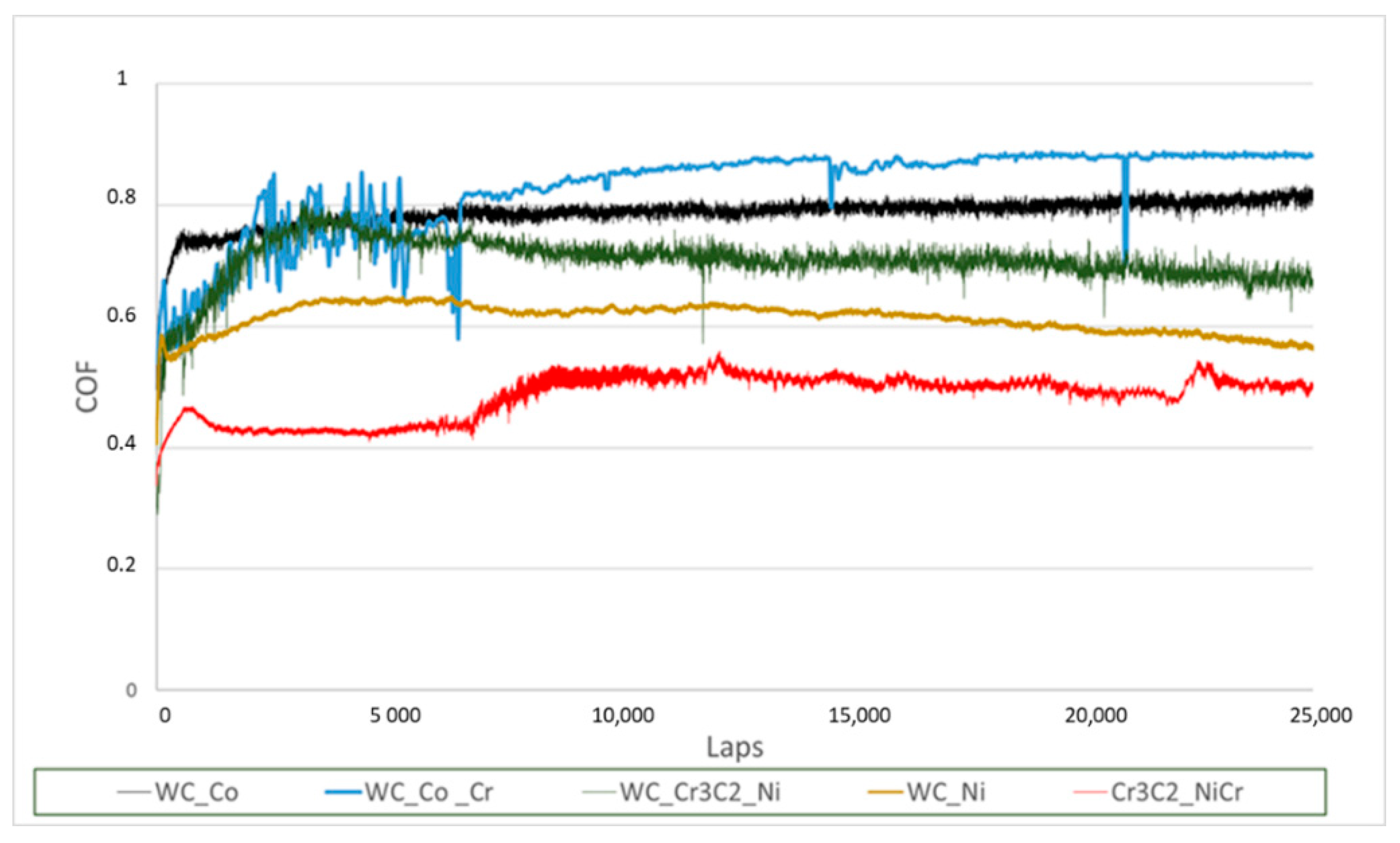
3.2. Tribological Properties

Figure 8 shows friction coefficient evolution during tests, while Table 4 represents the average values and friction fluctuation (standard deviation). The average friction coefficient was calculated after 5000 laps (219 m). Comparing friction coefficient evolution, the following conclusion can be drawn.
An increase in friction coefficient was observed over an initial sliding distance of about 0–1000 laps for all the coatings. After this period, WC-Co coating showed a stable friction coefficient compared with the other tested coatings.
Comparing all the coatings, WC-Co and WC-Co-Cr friction coefficient evolution were the highest among all coatings, but WC-Co was also more stable during the whole test. As shown in Table 4 the fluctuation of friction coefficient for WC-Co coating is much less than the other coating. The high fluctuations of the other coatings can be due to the plastic deformation mechanism.
At the beginning of the tribological test, few asperities of the coating surface are in contact with the alumina ball, which caused high contact stresses on the surface. The asperities wear away as the sliding progresses, and the initial surface roughness lowers, with a consequent decrease in friction coefficient.
Due to the higher hardness of WC-Co, lower asperity and consequently lower deformation of the surface were observed, leading to a more stable friction coefficient.
Furthermore, the increase in temperature, caused by the rolling motion, can make the material softer, resulting in desegregation of the matrix with a consequent higher degree of fluctuation. This fact is evident for Cr3C2-NiCr coating which can be due to the easy detachment of Cr3C2 particles from the matrix.
The maximum values of friction coefficient and their standard deviation of HP-CS coatings were compared to the value of the carbon steel substrate, as reported in Table 4. As can be noted, even if WC-Co does not exhibit the maximum friction coefficient value, it appears more suitable for brake application due to its stable behaviour observed during the friction coefficient tests, as shown in Figure 8.
The friction coefficient of WC-Co obtained in this investigation was compared with the base carbon steel and literature data [14,32]. As can be seen from the values reported in Table 5, all coatings exhibit higher friction coefficient values compared to the base carbon steel suggesting the advantage of using a noble coating to increase the properties of the base steel without altering the weight of the brake due to the low thickness of the coating.
In Figure 9a–e the three-dimensional wear tracks of the HP-CS coating obtained in this investigation were reported.
As shown in Figure 9 the profile of the wear track is not evident for all the samples except Cr3C2-NiCr, one, for which a well-defined groove can be observed (Figure 9d). Cr3C2-NiCr is the only coating tungsten carbide-free, then it can be assumed the positive effect of WC presence on the wear resistance. With the purpose to get more insights into the whole tribosystem, the wear scar diameter of the alumina ball counterbody was also investigated. Wear scar diameter measurements were performed using an average diameter formed on two tests for each sample.
Comparing the ball wear scar diameter (Table 6), the two coatings containing WC-Co induce higher wear on alumina with respect to other samples. No significant difference was observed between WC-Ni and Cr3C2-NiCr samples. During the rolling motion between coating and counterpart, the load is applied onto the irregularities which can lead to high contact stress. At the beginning of sliding, this was the major wear mechanism. Moreover, wear debris formed during the tribological test can be entrapped between the two parts playing as three-body abradants. The higher ball wear scar revealed for WC-Co may be due to the high hardness of the coating which abrades the sphere to a greater extent by increasing the third body phenomena.
These results underline that the coatings realized with HP-CS technology exhibit a very high wear resistance, but with this test equipment, it is not possible to evaluate the wear rate values.
Figure 10, Figure 11, Figure 12, Figure 13 and Figure 14 show SEM micrographs and magnification of the investigated coatings wear tracks, while Figure 15, Figure 16, Figure 17, Figure 18 and Figure 19 represent the SEM images and the correspondent EDS performed inside the wear tracks.
An uneven wear track was observed for WC-Cr3C2-Ni coating. Z contrast images highlight the different compositions inside and outside the wear track (see Figure 10 relative to WC-Cr3C2-Cr sample). Indeed, evidence of a higher content of elements with higher atomic numbers inside the track is proved by the higher brightness. Details reported in micrographs at higher magnification indicate the presence of well-defined particles parallelepiped shaped, attributable to WC, according to Z contrast images supported by EDS analysis (see Figure 15). Comparing the two spectra, reported in Figure 15b, can be noticed, a small intense oxygen peak in spectrum 1, suggesting oxidation phenomena. In the area where tungsten is present to large extent, neither chromium nor nickel can be observed, suggesting a preferential binder removal as a consequence of the sliding contact with the alumina ball. Moreover, the simultaneous application of high temperature and pressure to the coating can cause local sintering of Al2O3 leading to some amount of transferred counterbody material on the coating surface. The transfer from the ball can be seen by the high peak present in spectrum 2. The presence of aluminium oxide is also well evidenced by EDS (grey areas in Figure 15), indicating the adhesion of material coming from the counterface. The adhesive mechanism, derived from the transfer from the ball, may be responsible for the oscillation trend of the friction coefficient.
The spectrum acquired in the grey areas also shows the presence of nickel, chromium and tungsten, derived from the investigated coating.
As for WC-Cr3C2-Ni coating also WC-Ni showed a non-uniform wear track and different composition inside and outside the wear track, as proved by the significant different contrast. In this case, the binder removal occurred in less extent with respect to sample WC-Cr3C2-Ni. Indeed, carbide grains are less well shaped than in the previous case because they are still well surrounded by the nickel matrix. EDS spectra confirm the morphological evidence. Comparing the two spectra reported in Figure 16 a peak of alumina, due to a transfer from the ball, is present in some part of the wear track as is evident from spectrum 2 of Figure 16. Again, oxidation phenomena can be observed, in both the analyzed point (spectra 1 and 2). In addition, some cracks are present inside the wear track.
The wear mechanisms of WC-Co-Cr can be considered similar to those observed in the previous cases. Elemental analysis of the wear track revealed the presence of a high peak (spectrum 1) of ‘Al’ indicating alumina adhesion from the ball. The presence of ‘O’ inside the wear track, detected in spectrum 1, suggests in-situ formed tribo-oxides phenomena.
Moreover, as for the previous coatings, preferential binder removal was observed.
As for Cr3C2-NiCr, a more defined wear track is observed. Some cracks were detected inside the wear track, which can be observed at low and high magnifications. Furthermore, in the present case, the preferential removal of binder can be supposed by observing the intensity ratio between nickel and chromium in different areas. This difference was also confirmed by EDS analysis where, by comparing the two analyzed areas, the variation in Ni and Cr are confirmed. In the case of the Cr3C2-NiCr coating, alumina was not found. Oxidation phenomena cannot be excluded, although they are not evident from the spectra. As for WC-Co, the EDS analysis made on the wear track reveals the presence of W, Co, Al and O elements. As can be noticed in spectrum 1 ‘O’ and ‘Al’ are the predominant elements followed by ‘Co’ indicating that the resulting tribolayer is basically a combination of oxidized elements from the coating as well as alumina from the ball counterpart.
From EDS analysis and backscattered images of the wear tracks, some conclusions about the principal wear mechanisms can be made. The wear mechanism was the combination of abrasive, adhesive and oxidative wear mechanisms. In particular, adhesion of alumina ball, with consequent formation of local junctions was observed. Moreover, during tribological tests, unsupported grains, such as those of carbide, can be easily physically removed or pulled out thanks to enhanced grooving and the removal of the binder phase. Wear debris particles are produced during wear when the coated surface deforms plastically, which occurs during repeated wear cycles, resulting in wear debris fragmentation and the production of fine particles. While some of these particles are carried away, many could be trapped in the wear tracks. Further wear causes these small wear debris particles to oxidize, become compacted by normal and shear pressures, and form a tribo-oxide layer. This tribo-oxide layer can be beneficial as it can reduce wear rate. Such a process could account for the not significant differences in terms of wear resistance observed between WC-Cr3C2-Ni, WC-Ni, WC-Co-Cr and WC-Co. The visible track and higher wear observed for Cr3C2-NiCr is supposed to principally be the result of the weaker Cr bond of the coating [31], which resulted in excessive particles pulling out and consequently acting as a third abrasive body detaching much material from the coating itself.

3.3. Thermal Properties

As reported in the introduction of this manuscript a further property useful to evaluate the brake performance is thermal diffusivity which is quite difficult to evaluate owing to the unknown structure and composition of the coating layer. However, an estimate of α of the best-performing coatings can be obtained on the basis of the powder composition and literature data [33,34,35]. Data reported in Table 7 show an excellent value of α for the WC-Co coating.

4. Conclusions

In this paper, coatings for aircraft brake applications produced with HP-CS technology were investigated as a potential alternative to the sintered-sintered steel currently used [36]. It is useful to mention that the ideal coating material for the best braking action should exhibit: (i) high friction coefficient and wear resistance, respectively; (ii) high thermal diffusivity; (iii) good adhesion to the substrate; (iv) a compact microstructure; (v) very light in order to reduce the total weight of the vehicle and (vi) design and production should be low cost. Results obtained in this investigation using the HP-CS technology in only a set of spray parameters suggest that the WC-Co coating can be considered as a potential coating layer on carbon steel for brake application. In fact, WC-Co exhibits high friction coefficient value and, especially, high stability during tribological tests. Comparing the alumina ball abrasion, WC-Co coatings manifest the higher wear resistance compared to the other coatings investigated and, therefore, the best wear behaviour. Furthermore, the elevated thermal properties guarantee the best heat transfer useful to dissipate the heat generated during the braking action. On the other hand, among all the coatings it showed lower adhesion due to its high hardness value [37]. In fact, increasing the coating hardness implies a decrease in plastic deformation and, therefore, a lower adhesion capacity.
Another fundamental aspect is related to the fact that in the case of configurations of the sintered-sintered steel type, a double sintering process must be carried out.
In this case, however, a single additive process must be performed. Furthermore, it is possible to use a common carbon steel coated with an adequate layer of a more noble material.
In the light of these results, future work will be addressed to investigate the variation and stability of friction coefficient (dynamic and/or static), wear rate of the coating material as a function of temperature and corrosion resistance issues to further support the use of HP-CS technology for brake applications. Furthermore, future activities will regard the pre-industrialization phase, in which brake prototypes will be realized with the application of the different coatings investigated. On these prototypes’ friction, mechanical and thermal properties will be deeply studied. Specifically, fretting wear tests and specific thermal tests will be carried out.

Author Contributions

Conceptualization, M.G., G.G.d.C. and F.B.; methodology, M.G. and F.B.; software G.G.d.C.; validitation M.G., G.G.d.C. and F.B.; formal analysis M.G. and G.G.d.C.; investigation M.G., G.G.d.C. and F.B.; resource F.B., data curation M.G., G.G.d.C. and F.B.; writing—original draft, M.G., G.G.d.C. and F.B.; writing—review and editing, M.G., G.G.d.C. and F.B.; visualization; supervision F.B.; project administration F.B. All authors have read and agreed to the published version of the manuscript.

Funding

This research was performed within the E-BRAKE project, which has recieved funding from Clean Sky 2 Joint Undertaking programme under the European Union’s Horizon 2020 Research and Innovation. Program under grant agreement No. 821079.

Data Availability Statement

Not applicable.

Acknowledgments

All autors gratefully thank the European Commission and the Clean Sky 2 Joint Under.

Conflicts of Interest

The authors declare no conflict of interest.

References

  1. Krenkel, W.; Heidenreich, B.; Renz, R. C/C–SiC composites for advanced friction systems. Adv. Eng. Mater. 2002, 4, 427–436. [Google Scholar] [CrossRef]
  2. Awasthi, S.; Wood, J.L. Carbon/Carbon Composite Materials for Aircraft Brakes. Ceram. Eng. Sci. Proc. 1988, 9, 553–560. [Google Scholar]
  3. Guan, Q.F.; Li, G.Y.; Wang, H.Y.; An, J. Friction-wear characteristics of carbon fiber reinforced friction material. J. Mater. Sci. 2004, 39, 641–643. [Google Scholar] [CrossRef]
  4. Vasiljević, S.; Glišović, J.; Stojanović, B.; Vencl, A. Review of the coatings used for brake discs regarding their wear resistance and environmental effect. Proc. Inst. Mech. Eng. Part J J. Eng. Tribol. 2021, 236, 1932–1949. [Google Scholar] [CrossRef]
  5. Champagne, V.K. The Cold Spray Materials Deposition Process; Elsevier Science & Technology: Cambridge, UK, 2007. [Google Scholar]
  6. Karthikeyan, J. The advantages and disadvantages of the cold spray coating process. In The Cold Spray Materials Deposition Process Fundamentals and Applications; Champagne, V.K., Ed.; Woodhead Publishing Limited: Cambridge, UK, 2007; pp. 62–71. [Google Scholar]
  7. Klinkov, S.V.; Kosarev, V.F.; Rein, M. Cold spray deposition: Significance of particle impact phenomena. Aerosp. Sci. Technol. 2005, 9, 582–591. [Google Scholar] [CrossRef]
  8. Singh, S.; Raman, R.K.S.; Berndt, C.C.; Singh, H. Influence of Cold Spray Parameters on Bonding Mechanisms: A Review. Metals 2021, 11, 2016. [Google Scholar] [CrossRef]
  9. Decker, M.K.; Neiser, R.A.; Gilmore, D.; Tran, H.D. Microstructure and Properties of Cold Spray Nickel. In Proceedings of the International Thermal Spray Conference (2001), Singapore, 28–30 May 2001; pp. 433–439. [Google Scholar]
  10. Van Steenkiste, T.H.; Smith, J.R.; Teets, R.E. Aluminum coatings via kinetic spray with relatively large powder particles. Surf. Coat. Technol. 2002, 154, 237–252. [Google Scholar] [CrossRef]
  11. Shukla, V.; Elliott, G.S.; Kear, B.H. Nanopowder deposition by supersonic rectangular jet impingement. J. Therm. Spray Technol. 2000, 9, 394–398. [Google Scholar] [CrossRef]
  12. Rima, R.S.; Karthikeyan, J.; Kay, C.M.; Lindemann, J.; Berndt, C.C. Microstructural characteristics of cold-sprayed nanostructured WC–Co coatings. Thin Solid Films 2002, 416, 129–135. [Google Scholar]
  13. Vlcek, J.; Gimeno, L.; Huber, H.; Lugscheider, E. A Systematic Approach to Material Eligibility for the Cold Spray Process. J. Therm. Spray Technol. 2005, 14, 125–133. [Google Scholar] [CrossRef]
  14. Chen, J.; Song, H.; Liu, G.; Ma, B.; An, Y.; Jia, L. Cold Spraying: A New Alternative Preparation Method for Nickel-Based High-Temperature Solid-Lubrication Coating. J. Therm. Spray Technol. 2019, 29, 1892–1901. [Google Scholar] [CrossRef]
  15. Yandouzi, M.; Sansoucy, E.; Ajdelsztajn, L.; Jodoin, B. WC-based cermet coatings produced by cold gas dynamic and pulsed gas dynamic spraying processes. Surf. Coat. Technol. 2007, 202, 382–390. [Google Scholar] [CrossRef]
  16. Pawlowski, L. The Science and Engineering of Thermal Spray Coatings, 2nd ed.; Wiley: Hoboken, NJ, USA, 2007. [Google Scholar]
  17. Sapate, S.G.; Roy, M. Thermal Sprayed Coatings and Their Tribological Performances; IGI Global Publications: Hershey, PA, USA, 2015; pp. 193–226. [Google Scholar]
  18. Bhosale, D.G.; Rathod, W.S.; Nagaraj, M. High-temperature erosion and sliding wear of thermal sprayed WC–Cr3C2–Ni coatings. Mater. High Temp. 2021, 38, 464–474. [Google Scholar] [CrossRef]
  19. Berger, L.-M.; Saaro, S.; Naumann, T.; Wiener, M.; Weihnacht, V.; Thiele, S.; Suchánek, J. Microstructure and properties of HVOF-sprayed chromium alloyed WC–Co and WC–Ni coatings. Surf. Coat. Technol. 2008, 202, 4417–4421. [Google Scholar] [CrossRef]
  20. Siwak, P.; Garbiec, D. Microstructure and mechanical properties of WC–Co, WC–Co–Cr3C2 and WC–Co–TaC cermets fabricated by spark plasma sintering. Trans. Nonferr. Met. Soc. China 2016, 26, 2641–2646. [Google Scholar] [CrossRef]
  21. Bhagat, R.B.; Conway, J.C.; Amateau, M.F.; Brezler, R.A. Tribological performance evaluation of tungsten carbide-based cermets and development of a fracture mechanics wear model. Wear 1996, 201, 233–243. [Google Scholar] [CrossRef]
  22. Wang, H.; Wang, X.; Song, X.; Liu, X.; Liu, X. Sliding wear behavior of nanostructured WC–Co–Cr coatings. Appl. Surf. Sci. 2015, 355, 453–460. [Google Scholar] [CrossRef]
  23. Ji, G.; Li, C.; Wang, Y.; Li, W. Microstructural characterization and abrasive wear performance of HVOF sprayed Cr3C2–NiCr coating. Surf. Coat. Technol. 2006, 200, 6749–6757. [Google Scholar] [CrossRef]
  24. Guilemany, J.M.; Espallargas, N.; Suegama, P.H.; Benedetti, A.V. Comparative study of Cr3C2–NiCr coatings obtained by HVOF and hard chromium coatings. Corros. Sci. 2006, 48, 2998–3013. [Google Scholar] [CrossRef]
  25. Kevin, P.S.; Tiwari, A.; Seman, S.; Mohamed, S.A.B.; Jayaganthan, R. Erosion-Corrosion Protection Due to Cr3C2-NiCr Cermet Coating on Stainless Steel. Coatings 2020, 10, 1042. [Google Scholar] [CrossRef]
  26. He, B.; Zhang, L.; Yun, X.; Wang, J.; Zhou, G.; Chen, Z.; Yuan, X. Comparative Study of HVOF Cr3C2–NiCr Coating with Different Bonding Layer on the Interactive Behavior of Fatigue and Corrosion. Coatings 2022, 12, 307. [Google Scholar] [CrossRef]
  27. Trabadelo, V.; Giménez, S.; Iturriza, I. Microstructural characterisation of vacuum sintered T42 powder metallurgy high-speed steel after heat treatments. Mater. Sci. Eng. A 2009, 499, 360–367. [Google Scholar] [CrossRef]
  28. Bull, S.J.; Berasetegui, E.G. An overview of the potential of quantitative coating adhesion measurement by scratch testing. Tribol. Int. 2006, 39, 99–114. [Google Scholar] [CrossRef]
  29. Sundararajan, G.; Chavan, N.M.; Sivakumar, G.; Phani, P.S. Evaluation of Parameters for Assessment of Inter-Splat Bond Strength in Cold-Sprayed Coatings. J. Therm. Spray Technol. 2010, 19, 1255. [Google Scholar] [CrossRef]
  30. Dotta, A.L.B.; Costa, C.A.; Farias, M.C.M. Tribological behavior of alumina obtained by low-pressure injection molding using factorial design. Tribol. Int. 2017, 114, 208–220. [Google Scholar] [CrossRef]
  31. Mishra, T.K.; Kumar, A.; Sinha, S.K. Experimental investigation and study of HVOF sprayed WC-12Co, WC-10Co-4Cr and Cr3C2-25NiCr coating on its sliding wear behaviour. Int. J. Refract. Met. Hard Mater. 2021, 94, 105404. [Google Scholar] [CrossRef]
  32. Granata, M.; Gautier di Confiengo, G.; Scamardella, D.; Bellucci, F. Potential Coatings for Aircraft Brakes Application. Part I: Thermal Spray Coatings. Int. J. Astronaut. Aeronaut. Eng. 2021, 6, 056. [Google Scholar]
  33. Mahaidin, A.A.; Jaafar, T.R.; Budin, S.; Selamat, M.A. The effect of cobalt, vanadium carbide and PKS activated carbon addition on WC-Co Composite: A study using taguchi method. J. Mech. Eng. 2017, 5, 42–52. [Google Scholar]
  34. Chen, K.; Xiao, W.; Li, Z.; Wu, J.; Hong, K.; Ruan, X. Effect of Graphene and Carbon Nanotubes on the Thermal Conductivity of WC–Co Cemented Carbide. Metals 2019, 9, 377. [Google Scholar] [CrossRef]
  35. Ksiazek, M.; Nejman, I.; Boron, L. Investigation on Microstructure, Mechanical and Wear Properties of HVOF Sprayed Composite Coatings (WC–Co + CR) On Ductile Cast Iron. Materials 2021, 14, 328. [Google Scholar] [CrossRef]
  36. Umbria Aerospace System, UAS, (via Bufaloro 21, 06089, Torgiano, PG, Italy) Brake Material selection criteria, Doc Number DR-R18001-00-02, 13-Dec-2018, Private Communication.
  37. Burnett, P.J.; Rickerby, D.S. The relationship between hardness and scratch adhesion. Thin Solid Films 1987, 154, 4. [Google Scholar] [CrossRef]
Figure 1. HRC imprints of (a) WC-Cr3C2-Ni; (b) WC-Ni; (c) WC-Co-Cr; (d) Cr3C2-NiCr and (e) WC-Co.
Metals 12 01558 g001aMetals 12 01558 g001b
Figure 2. Scratch track of WC-Cr3C2-Ni coatings.
Metals 12 01558 g002
Figure 3. Scratch track of WC-Ni coatings.
Metals 12 01558 g003
Figure 4. Scratch track of WC-Co-Cr coatings.
Metals 12 01558 g004
Figure 5. Scratch track of Cr3C2-NiCr coatings.
Metals 12 01558 g005
Figure 6. Scratch track of WC-Co coatings.
Metals 12 01558 g006
Figure 7. Scratch test results and their standard deviation.
Metals 12 01558 g007
Figure 8. WC-Cr3C2-Ni, WC-Ni, WC-Co-Cr, Cr3C2-NiCr and WC-Co.
Metals 12 01558 g008
Figure 9. Three-dimensional image of the wear tracks of (a) WC-Cr3C2Ni-Cr; (b) WC-Ni; (c) WC-Co-Cr; (d) Cr3C2-NiCr and (e) WC-Co.
Metals 12 01558 g009aMetals 12 01558 g009b
Figure 10. SEM micrograph (a) and a magnification (b) of wear tracks of WC-Cr3C2-Ni.
Metals 12 01558 g010
Figure 11. SEM micrograph (a) and a magnification (b) of wear tracks of WC-Ni.
Metals 12 01558 g011
Figure 12. SEM micrograph (a) and a magnification (b) of wear tracks of WC-Co-Cr.
Metals 12 01558 g012
Figure 13. SEM micrograph (a) and a magnification (b) of wear tracks of Cr3C2-NiCr.
Metals 12 01558 g013
Figure 14. SEM micrograph (a) and a magnification (b) of wear tracks of WC-Co.
Metals 12 01558 g014
Figure 15. SEM micrograph (a) and EDS analysis (b) of WC-Cr3C2-Ni.
Metals 12 01558 g015
Figure 16. SEM micrograph (a) and EDS analysis (b) of WC -Ni.
Metals 12 01558 g016aMetals 12 01558 g016b
Figure 17. SEM micrograph (a) and EDS analysis (b) of WC-Co-Cr.
Metals 12 01558 g017
Figure 18. SEM micrograph (a) and EDS analysis (b) of Cr3C2-Ni Cr.
Metals 12 01558 g018
Figure 19. SEM micrograph (a) and EDS analysis (b) of WC-Co.
Metals 12 01558 g019aMetals 12 01558 g019b
Table 1. High-pressure cold spray process parameters.
ItemValue
Gas usedN2
Inlet gas temperature1100 °C
Inlet gas pressure35 bar
Spray distance30 mm
Powder feed rate40 g/min
Inlet powder temperature150 °C
Gun travelling speed80 mm/s
Table 2. Coatings thickness.
CoatingThickness (mm)
WC-Cr3C2-Ni0.55
WC-Ni0.54
WC-Co-Cr0.52
Cr3C2-NiCr0.60
WC-Co0.80
Table 3. HRC values of carbon steel substrate and HP-CS coatings.
MaterialsHRC Hardness Value
Steel21.5 ± 1.00
WC-Cr3C2-Ni54.72 ± 0.71
WC-Ni58.22 ± 1.93
WC-Co-Cr55.16 ± 1.83
Cr3C2-NiCr55.22 ± 2.39
WC-Co61 ± 2.18
Table 4. Friction coefficient values and their standard deviation.
MaterialsAverage Coefficient
Steel0.58 ± 0.02
WC-Cr3C2-Ni0.71 ± 0.03
WC-Ni0.61 ± 0.02
WC-Co-Cr0.84 ± 0.02
Cr3C2-NiCr0.49 ± 0.03
WC-Co0.79 ± 0.01
Table 5. Friction coefficients of carbon steel, WC produced by HVOF, Inconel 625 and WC-Co coatings obtained with HP-CS technology.
MaterialsAverage Coefficient
Steel0.58 ± 0.02
Inconel 625 [14]0.76 ± 0.03
Tungsten Carbide (HVOF process) [32]0.87 ± 0.02
WC-Co0.79 ± 0.01
Table 6. Ball diameter measurements at the end of the tribological test.
MaterialsBall Diameter (mm)
WC-Cr3C2-Ni2.42 ± 0.03
WC-Ni1.02 ± 0.02
WC-Co-Cr2.98 ± 0.03
Cr3C2-NiCr0.91 ± 0.18
WC-Co3.17 ± 0.02
Table 7. Thermal diffusivity of: (i) low carbon steel, (ii) WC-Co and WC-Co-Cr HP-CS investigated coatings.
Thermal Diffusivity (m2/s)
Low Carbon Steel1.404 × 10−5
WC-Co [34]1.674 × 10⁻⁵
WC-Co-Cr [35]1.121 × 10⁻⁵
Publisher’s Note: MDPI stays neutral with regard to jurisdictional claims in published maps and institutional affiliations.

