Article

Inclusion Removements in a Bottom-Stirring Ladle with Novel Slot-Porous Matched Dual Plugs

1
School of Iron and Steel, Soochow University, Suzhou 215137, China
2
Laiwu Technique Center, Shandong Iron & Steel Group Company Limited, Jinan 271104, China
*
Authors to whom correspondence should be addressed.
Metals 2022, 12(1), 162; https://doi.org/10.3390/met12010162
Submission received: 13 October 2021 / Revised: 19 December 2021 / Accepted: 10 January 2022 / Published: 17 January 2022

Abstract

:
The cleanness of steel has always been a big problem for secondary refining. In this work, a new method, which is coupled with slot and porous plugs, is proposed to improve the cleanness in steel. Water experiments and numerical simulations were performed to study this effect. Results revealed that when using slot-porous plugs, the flow field was obviously asymmetrical, and the circulation flow was pushed towards the porous side. Then, the removement of inclusions was increased to about 22.7% percent, comparing with traditional two-slot bottom stirring and reducing the dead zone area near the bottom of the ladle; however, the mixing time delay was 16%, comparing with traditional plugs. Then, in order to explain the reason for these phenomena, we established a mathematical model through large eddy simulation and discrete particle modeling (DPM). Results shows that the asymmetry flow field awoke the recirculation flow downwards after using slot-porous plugs, which would homogenize the flow at the bottom, promoting floating in steel. What is more, the velocity near the free surface was lowered; therefore, it could also stabilize the surface velocity as well, which is also beneficial for removing inclusions as well.

1. Introduction

With the rapid development of the steel industry, especially for electronics, aircraft, and ships, the requirement of clean steel is getting more and more strict. In modern steel-making process, the ladle refining plays an important role in adjusting steel components, removing harmful and dangerous elements and inclusions. Even though the technology of ladle refining has achieved great success in these years, the inclusions are still not easy to remove, especially for the smaller ones. As a result, improving ladle refining and enhancing the purity of steel is a hot topic.
As a bubble-driven tube, the ladle, which is responsible for the desulfurization, inclusion removements, and other chemical-related phenomena, depends on the good mixing and homogenization of molten steel. Chen et al. [1] investigated the effect of plug positions on the mixing behavior, showing that the shortest mixing time could be obtained when the two plugs were symmetrically arranged at half radii in the ladle bottom. Furthermore, Chen et al. [2] found that the angle of two plugs should be arranged within 60–90 degrees. In addition, Tang [3] improved the mixing behavior through an asymmetry injection of argon gas. The geometry of the bubble generator may also affect the ladle refining in the process. Owusu et al. [4] compared six kinds of injectors and found that more bubbles would be produced by small orifices, enhancing the mixing behavior in the ladle. Tan et al. [5] built a water model to show that, with the slit diameter increases, the mixing time and inclusion removal rate decreases. What is more, the slag eye increases with increasing slit diameter, and the slit angle has a positive influence on the formation of the slag eye. Except for the ladle structures stated above, the bubble generators (or plugs) are also quite essential for the refining effect. Practical measurements showed that in a slot plug, the velocity increases sharply with the gas pressure, while in a porous plug, it has a window that, when gas pressure continuous to grow, the velocity does not increase any more. Therefore, most steel plants adopted two-slot plug affiliations to improve the mixing of molten steel. During this process, the bubble floating would induce the buoyancy force to drive steel to flow and also remove inclusions in this way. There are two mechanisms [6] for removing inclusions now: One is through the bubble wake and the other one is bubble surface adhesion. Comparing with slot plug, the porous plug has a special porous structure that can generate more fine bubbles to entrap inclusions to improve the purity of molten steel. For example, Zheng [7] investigated the inclusion removement ratio in a wide range of gas flows and found that the removement ratio was obviously higher than that of the slot plug and the smaller bubbles were more efficient in removing inclusions. Wang [8] established a mathematical model that described bubble adhesion of inclusions, finding that the bubbles with sizes of 0.5–2 mm were most efficient to remove inclusions smaller than 50 μm, while, for the big inclusions, they were mostly removed by the bubble wake, which was accomplished more easily by bubbles larger than 2 mm [8]. Even though they have their own defects, they can be coupled together to make up with each other’s weaknesses to get a better refining effect.
In these years, computational fluid dynamics (CFD) have been widely used to realize the phenomenon with bubbly flow [8,9]. In the early models [3,9,10,11], the momentum equation of the liquid phase was solved using the void fraction of bubbles as in the multi-fluid model. The bubble aggregation and breakage were not taken into consideration. Sheng and Iron [12], using the Eulerian–Lagrandian model, considered the bubble breakup and the lift force in the simulation and compared those with the results of the water model. Then, Guo and Iron [13] successfully adopted this model in three-dimensional simulations. Recently, Duan et al. [14] investigated the role of each interphase force on the gas–liquid flow regime, including the drag force, lift force, virtual mas s force, and pressure gradient force. The bubble size distribution was considered according to the experimental result of Xie et al. [15]. In a series of works [16,17,18,19] by Liu and Li et al., they conceived CFD-PBM and LES-VOF-DPM as well as DBM model for revealing the slag entrainment, naked steel, and mixing behavior inside the ladle, and laid a solid foundation for recognizing the physical phenomenon during ladle refining. However, until now, the bubble interactions with different plugs have not been reported; thus, the bubble characteristics on the flow field as well as its effect on the inclusion removements still remain to be done.
In this work, the main innovations consist of three parts: (1) to improve the inclusion removement ratio through coupling with slot and porous plugs, (2) to establish a mathematical model that can be used to show the flow field in these slot-porous plugs, and (3) to reveal the reason why the removement ratio can be increased using this system. The work lays the foundation for the theory of a slot-porous plugs coupled system to improve the secondary refining effect.

2. Mathematical Model

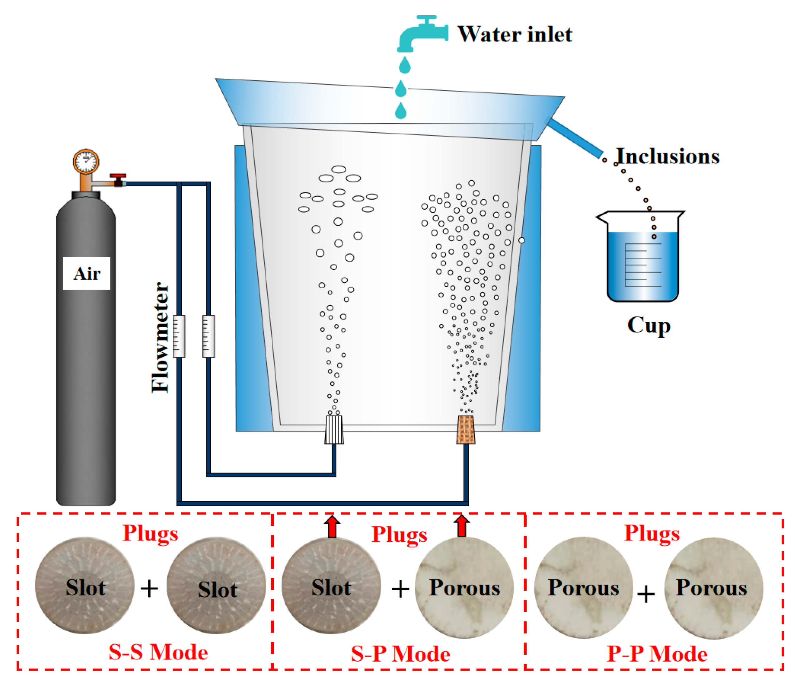
2.1. Similarity Principle for Water Model

An industrial size of a refining ladle of 100 tons was used as a prototype to design the experimental water model. The scale factor was 1:7, and the main parameters of the prototype and the model ladle are shown in Table 1.
Based on the ideal gas law, the Equation (1) was obtained:
ρ l , p g H p + p 0 p 0 = ρ g , p ( T 0 + 273.15 ) ρ g , 0 · 273.15
In this equation, the depth of the molten steel H p = 3350   mm , local atmosphere pressure p 0 = 101325 P a , the argon density at standard state ρ g , 0 = 1.785   kg/m 3 , the density of steel ρ l , p = 7100   kg/m 3 , and the temperature at the inlet of the plug T 0 = 1558   °C; therefore, the argon density at the inlet ρ g , p = 0.329   kg/m 3 .
With consideration of bubble expansion, the gas flowrate under high temperature is as follows:
Q g , p = ρ g , 0 ρ g , p Q g , 0 = 2.031   Q g , 0
where Q g , 0 is the volume flow rate of argon at a standard state. According to the principle of similarity, the flowing mainly originates from the buoyancy of bubbles from the bottom gas. Therefore, modified Froude numbers (Fr′) must be equal besides having geometric similarity for model and prototype. Modified Fr′ is defined as:
F r = ρ g , m u m 2 ρ l , m g H m = ρ g , p u p 2 ρ l , p g H p
Gas flow velocity can be represented as a function of the gas flowrate:
u = 4 Q π D 2
The Equation (3) was obtained according to the equation F r m = F r p :
u m u p = ρ g , p H m ρ l , m ρ l , p H p ρ g , m
Q g , m Q g , p = ρ g , p · d m 4 · H m · ρ l , m ρ l , p · d p 4 · H p · ρ g , m = 0.00251
Based on Equations (2) and (6), the following equation can be obtained:
Q g , m = 0.00251 Q g , p = 0.00251 × 2.031 × Q g , 0 = 0.0051   Q g , 0
where “m” and “p” represent model and prototype.
The system was made up of a water model, plugs, gas pipe, and air compressor, shown in Figure 1. The air was injected into the ladle through a compressor at 0.4 MPa, and a water tap was set above the water model, which injected water constantly at a fixed flow rate. The liquid dioctyl phthalate was used as a surrogation for non-metallic inclusions in steel. To homogenize the inclusions into the water model, the dioctyl phthalate was mixed with pure water and rotated in a stirred vessel with a rather high speed, and then injected in 1 s. The total volume of the dioctyl phthalate was 60 mL. Once the inclusions were floating to the top, the water would flow over the boundary and push the inclusions into the beaker. We monitored the inclusions in the beaker every 1 min. The monitored time was 10 min. The transient removement ratio in every minute can be calculated through the monitored liquid inclusions in every minute, divining with total volume of 60 mL. Two plugs were used in the ladle, however, with a different match. The first match was composed of two slot plugs (S-S mode). The second match was composed of one slot plug and one porous plug (S-P mode). The third match was composed of two porous ones (P-P mode). The type mostly used in today’s factory is the first mode, aiming at mixing alloy elements. The slot plug is made up of plexiglass with the radius of 17 mm and the slot thickness is 0.2 mm. By comparison, the material for making the porous plug is corundum (Al2O3), which can be used to refine bubbles when they are injected into the ladle.

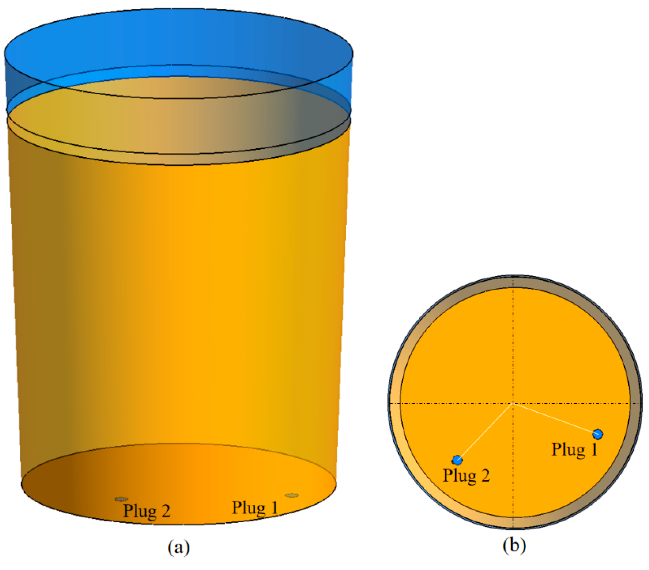
2.2. Simulation Model and Boundary Conditions

The computational domain included the fluid domain and two plugs in the bottom of the ladle, shown in Figure 2. One of them was located on the 0.78 radius of the ladle bottom and the other one was on the 0.71 radius of the ladle bottom. The angle of these two plugs was 114°. The free surface of the steel was a 500-mm distance from the top surface of ladle. The slag layer thickness was 80 mm. Hexahedral mesh was used to perform the simulation, and the total number was 1.06 million.
The geometry of the slab and properties of materials can be found in Table 1.

2.3. Mathematical Model

2.3.1. Mass Conservation Equation

The mass conservation equation for three phases (molten steel, slag, and air) is as follows:
( ρ m ) t + ( ρ m u ¯ m , i ) x i = 0
where u ¯ m , i is the filtered velocity of continuous phases, which can be elaborated as the integration of the filtered function multiplying velocity u m , i , and t is time. The term ρ m is mixture density, the equation of which can be written as follows:
ρ m = α l ρ l + α g ρ g
where α l and ρ l are volume fraction and density of molten steel, α s and ρ s are volume fraction and density of liquid slag, and α g and ρ g are volume fraction and density of air phase. For simplification, we used subscripts “l” to represent steel, “s” to represent slag, and “g” to represent air. The term α k is tracked with the following VOF equation:
( α i ) t + ( α i u ¯ m , i ) x i = 0
where ρ k is the density of kth phase and α k is the volume fraction constrained by the equation α l + α g = 1 .

2.3.2. Momentum Conservation Equation

Many previous works [20,21,22,23,24] reported that the large eddy simulation is feasible in predicting the vortexing flow in detail. In this method, large eddies are directly represented, whereas smaller ones are modeled to solve. Therefore, the large eddies are mathematically filtered and the smaller ones are modeled to close momentum equations. Then, the filtered time-dependent Navier–Stokes (N-S) equation can be written as follows:
( ρ m u ¯ m , i ) t + ( ρ m u ¯ m , i u ¯ m , j ) x j = P ¯ i x j + 2 x j [ μ effect , m ( S ¯ i j 1 3 δ i j S ¯ k k ) ] + ρ m g i + 6 π d p 3 · F i + F T , i
Here, the term P ¯ i is the static pressure, F i is the particle forces acting on steel, μ effect , m = μ m + μ t is the effective viscosity of mixture phase, μ m is the molecular viscosity of mixture phase, d p is the diameter of argon bubble, and μ t is the turbulent viscosity of mixture phase. In the VOF method, all the variables are averaged by the volume fraction of each phase. The equation of the surface tension force F T ,   i can be found in other works [25]. The filtered strain rate S ¯ i j is defined by:
S ¯ i j = 1 2 [ u ¯ i u ¯ j + u ¯ j u ¯ i ]
where δ i j represents the Kronecker symbol. The turbulent viscosity μ t = ρ m L s 2 | S ¯ i j | .
In this work, the L s is calculated by:
L s = min ( κ d , C s Δ )
where κ is a von Kármán constant equal to 0.4, d is the distance to the closest wall, C s is the Smagorinsky constant of 0.2, and Δ is calculated based on the volume of the structured cell using Δ = V 1 / 3 .

2.3.3. Bubble Transportation Model

In this work, the movements of discrete bubbles are tracked through the Lagrangian approach. To simulate the effect of bubbles on fluid flow, the interactions between the continuous phases and discrete bubbles were two-way coupling. For instance, the motion of particles can be simulated by integrating the force balance equation for each particle, which can be written as:
m p d u ¯ p ,   i d t = F i
where u ¯ p , i and m p represent the velocity and mass of bubbles and F i represents total forces acting on bubbles, which can be expressed as:
F i = F g ,   i + F b ,   i + F p ,   i + F d ,   i + F l ,   i + F v m ,   i
The terms on the right side of Equation [15] are gravitational force, buoyancy force, pressure gradient force, drag force, lift force, and virtual mass force.
Bubbles that are injected into SEN at room temperature would expand in molten steel, the density of which can be calculated through the ideal gas law:
p = ρ p R g T
Here, the bubble density at 20 °C is 1.78 kg/m3. The pressure p is standard atmospheric pressure, which can be assumed to be constant near the mold top. Based on this equation, the bubble density in the molten steel (1556 °C) is 0.266 kg/m3.

3. Results and Discussions

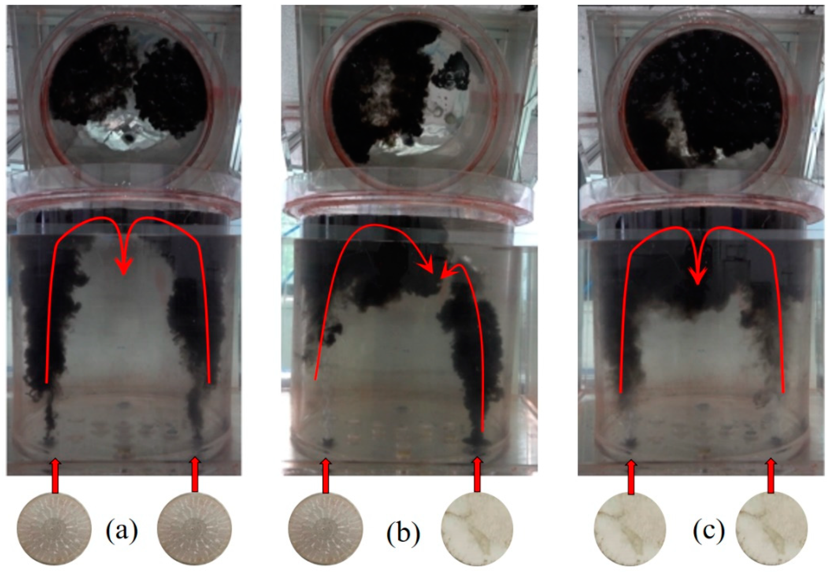
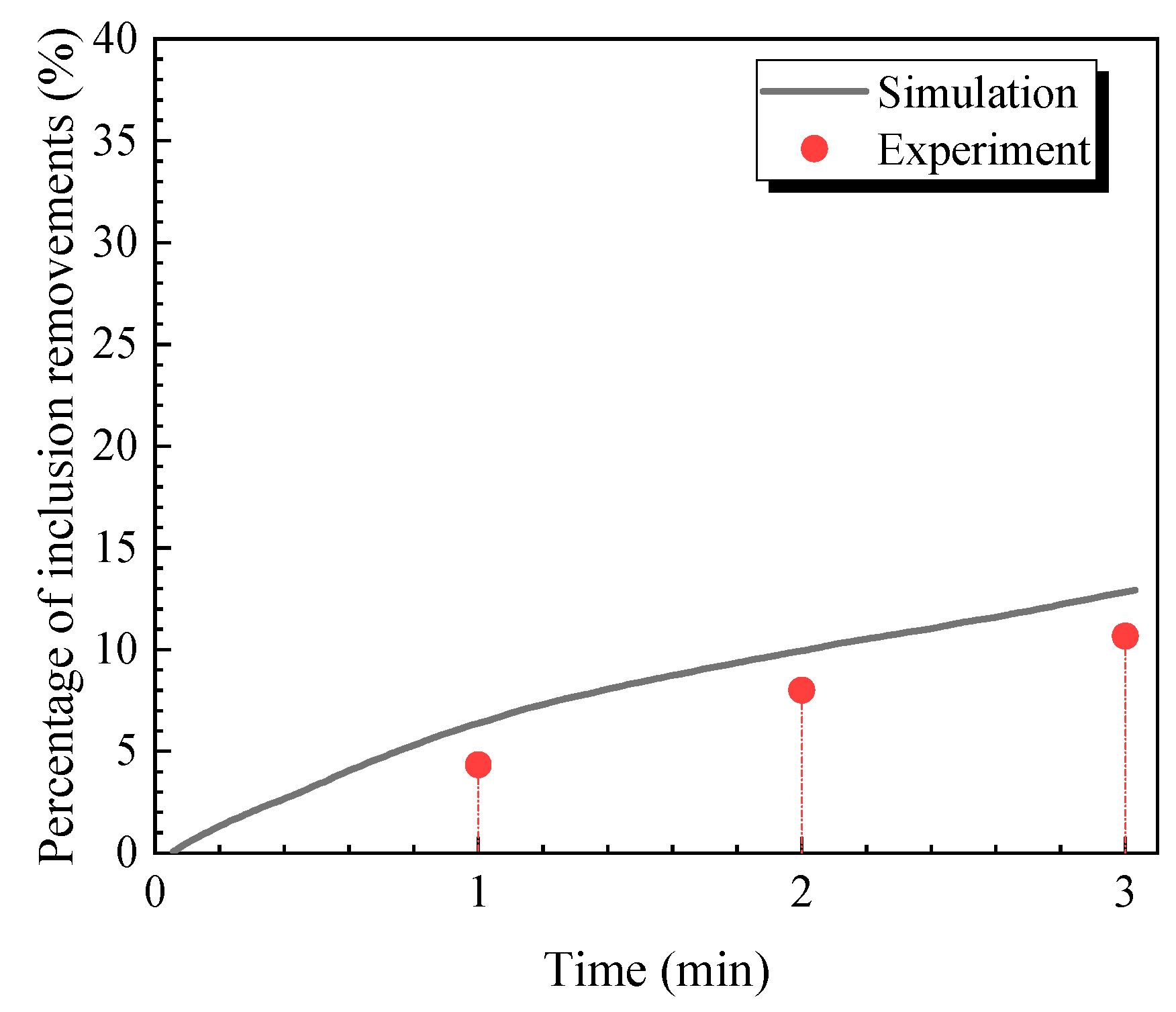
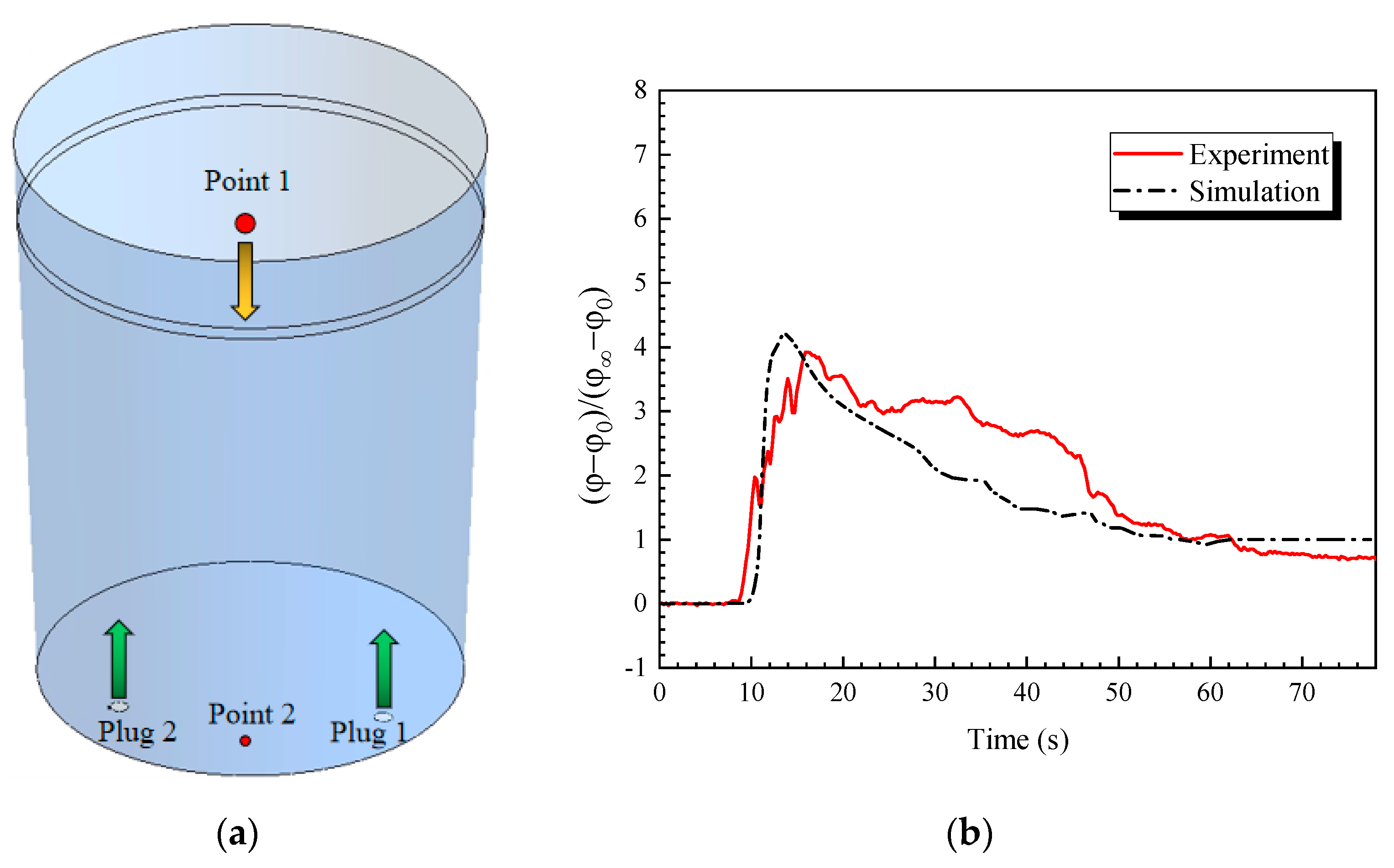
3.1. Validation of Mathematical Model

In order to validate the accuracy of the mathematical model, the transient removement of inclusions is calculated and compared with the water model. The parameters used in the simulation are shown in Table 1. Two different plugs were used at the same gas rate of 150 NL/min, and the results are shown in Figure 3. It can be seen from Figure 3 that, although the experiment value was smaller than that of the simulation result, the simulated and experimental results were quite similar with each other when time increased. The reason for this phenomenon is because there were some unavoidable inclusions that adhered to the wall of the ladle at the beginning of the experiment. Except for these differences stated above, the mathematical model was confirmed to be reliable.
In order to investigate the effect of plugs on the mixing behavior of steel, the KCl solution was added near the top of the ladle (Point 1) and the electric conductivity was inserted near the bottom (Point 2), which can be found in Figure 4a. The mixing time was determined as the time when the percentage of KCl concentration variation was less than 5%.
As the flow reached a steady state during simulation, the species-transport model is applied to track the liquid mixing in steel. It was assumed that the density of solution is equal to the density of liquid steel, then the equation can be written as follows:
φ t + · ( u m , i φ D e φ ) = 0
where φ is the dissolved liquid concentration and D e is the diffusion coefficient. Figure 4b shows the experimental and numerical non-dimensional variable change at Point 2. The solution was added at the time that flow reached a steady state and the time that was shown in the figure was recorded after that. The non-dimensional variable was described as (φφ0)/(φφ0) where φ is a steady value of the quantity obtained from both experiment and numerical calculations, and φ0 is the initial value in the ladle. It can be seen from Figure 4b that the simulation result was quite similar to the experiment result, indicating that the mathematical model in this work is reliable.

3.2. Similarity Principle for Water Model

The bubble profiles that were injected from a slot plug are shown in Figure 5. Three different flow rates were considered: 30 NL/min, 150 NL/min, and 300 NL/min. It should be noted that in this work, if there were no additional statements, the bubble flow rate written in this work was for the real ladle, no matter if it was in the water model or the simulation model. The transformation method can be found in Equation (2).
It can be seen from Figure 5 that, when the injection rate was 30 NL/min, the bubble size was quite large from the slot plug, and the size distribution was within a quite far range. With the increase of gas injection, a large number of bubbles was generated; the bubbles coalesced into many huge ones and also broke into smaller ones, which disturbed the ladle flow in a large scale.
By comparison, just as shown in Figure 6, the bubble size was quite fine with a round shape when the bubbles were injected from the porous plug. Additionally, although the size increased a little with the flow rate, the shape was still kept as round and the coalescence and breakage of bubbles were quite small.
Through using image J software statistics, the bubble size distribution of slot and porous plugs are shown in Figure 7. No matter which flow rate, the bubble range for slot plug was far beyond that in the porous plug, and, also, the bubble size was quite larger. By comparison, when using the porous plug, the bubble size was quite uniform, mostly ranging from 1–4 mm, which is beneficial for removing inclusions in the ladle [4,7].

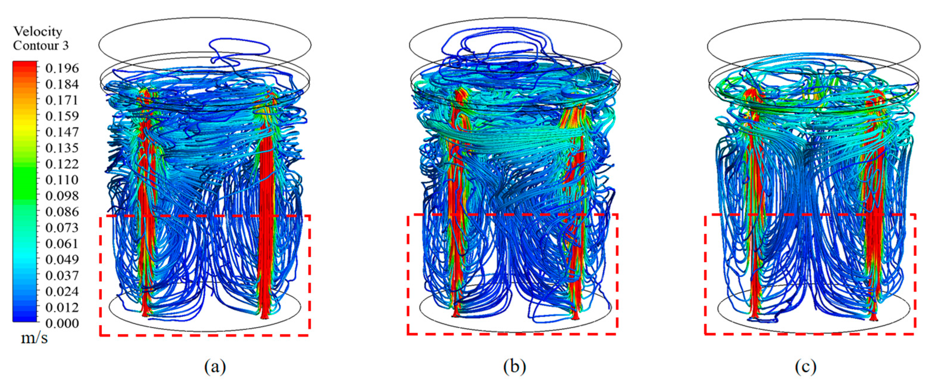
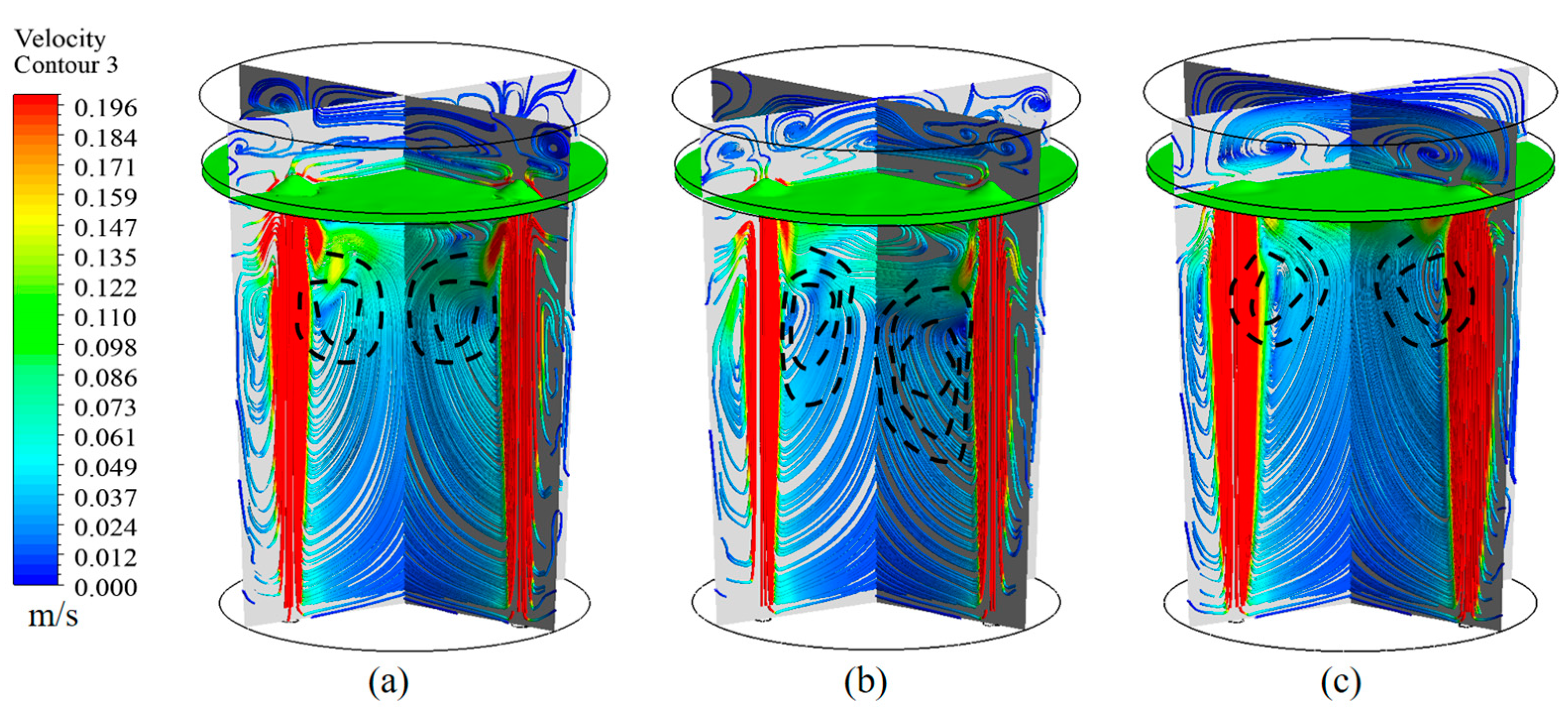
3.3. Flow Characteristics in Ladle

Figure 8 shows the transient behavior of the flow phenomenon inside the ladle. The black ink was injected to trace the flow stream of the fluid injections from two plugs. Easily seen, the injection fluid moved upward quickly to the top and crashed near the middle of the top. This may cause much kinetic loss in a real flow process. By comparison, if we replace one of them with a porous plug, the impingement area significantly offset to the replaced direction side. Additionally, the bubbles were greatly refined and distributed inside the mold, which may help remove more inclusions floating to the top.

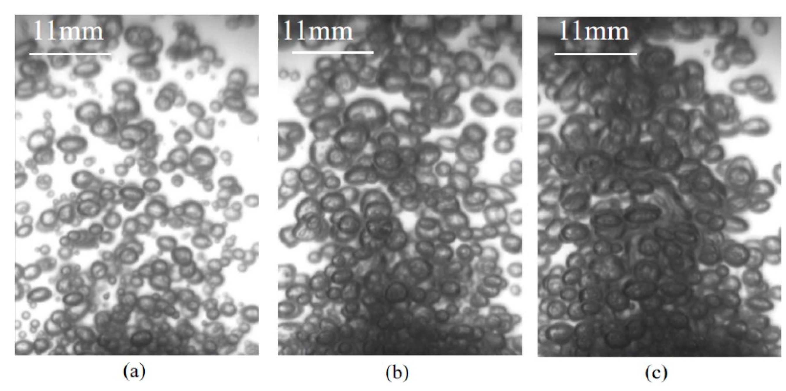
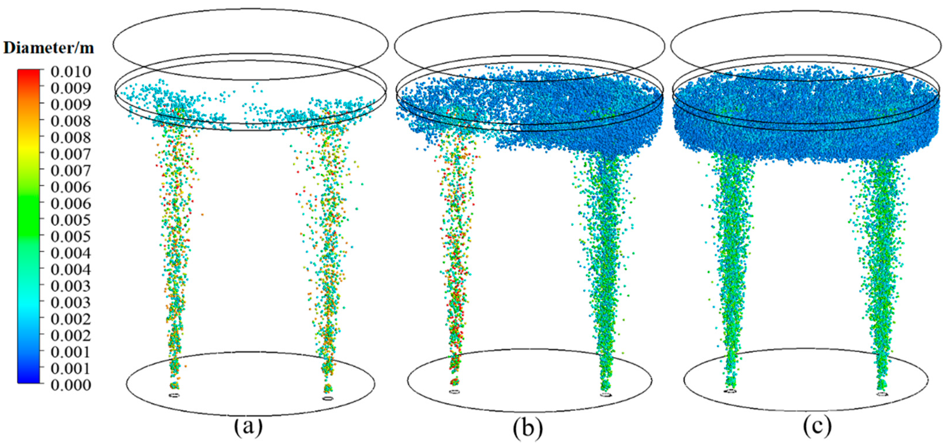
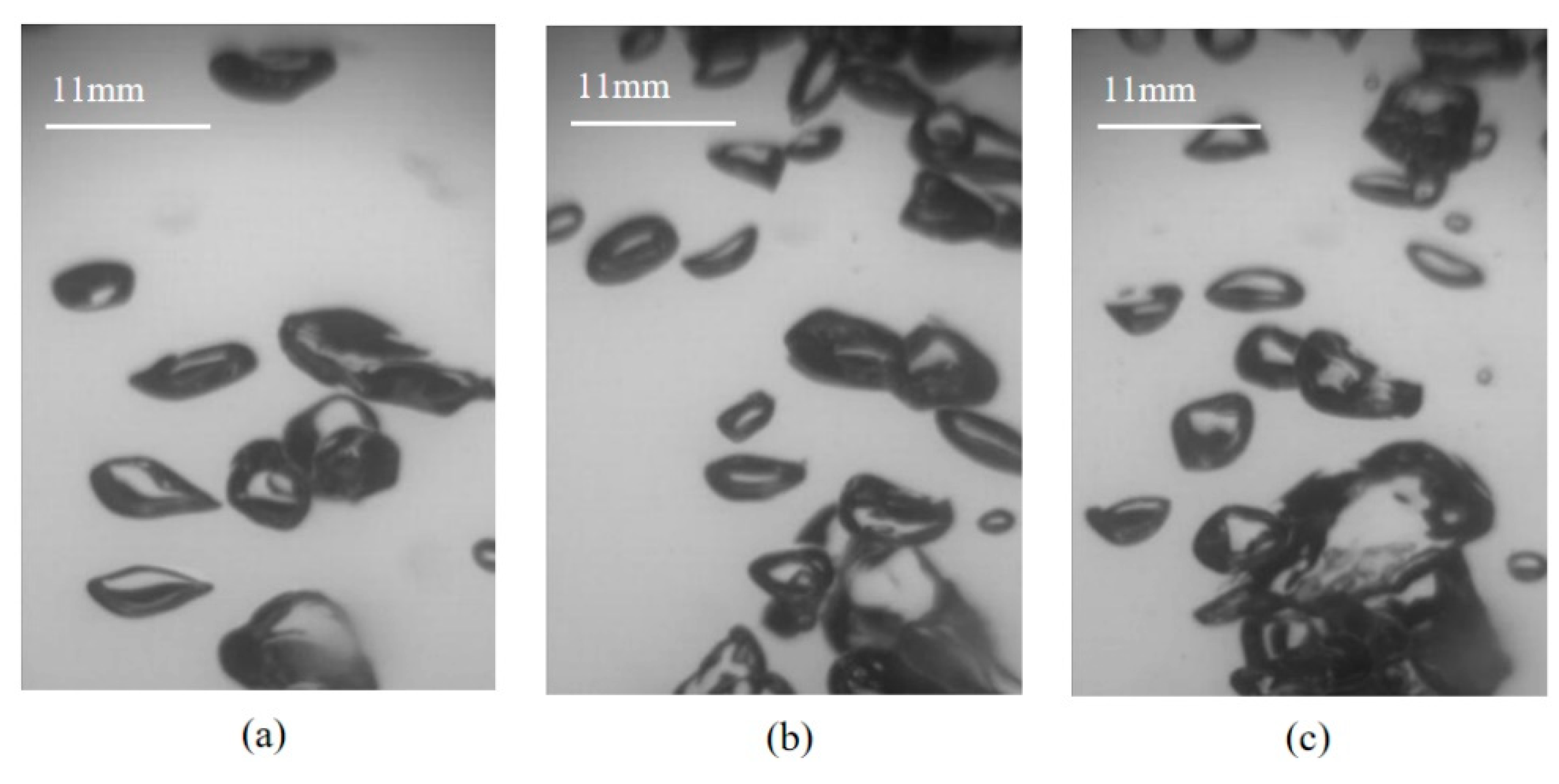
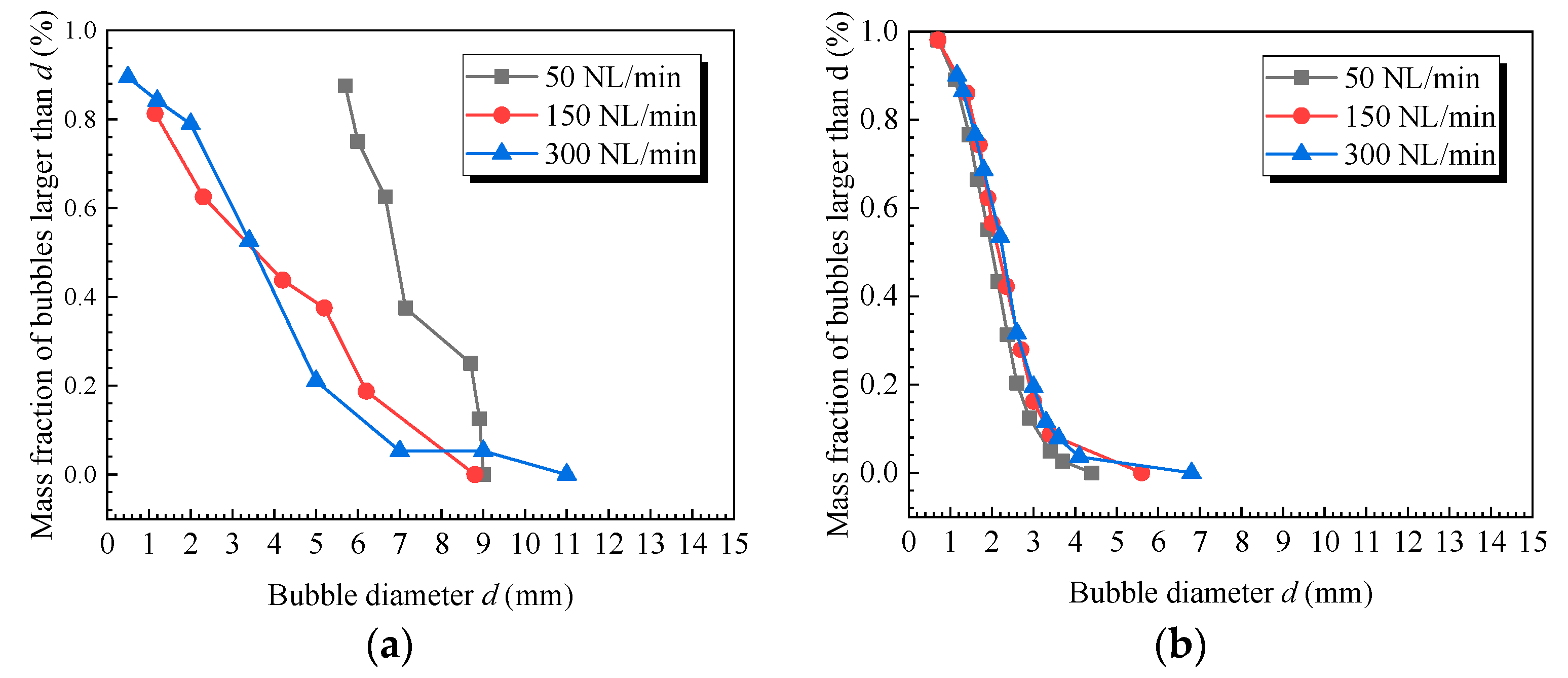
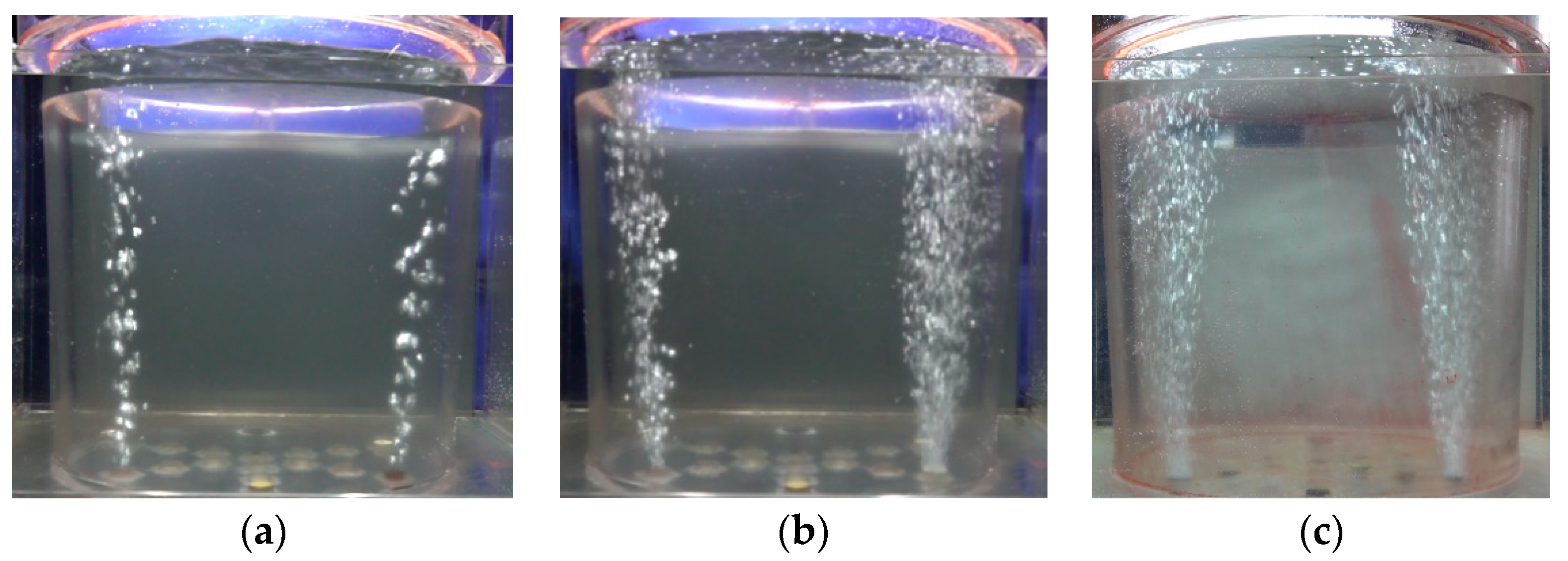
3.4. Bubble Distribution in the Ladle

The distribution of bubbles with different plugs is shown in Figure 9. It can be seen from Figure 9 that the bubble plume presented like a line when using the double slot plugs, while it transformed like a horn when one was replaced by a porous plug, as shown in Figure 9b. In addition, when the two double plugs were all porous plugs, shown in Figure 9c, then the plumes were obviously larger than that in Figure 9a. The reason for this phenomenon is because small bubbles were large in number, which will be dispersed more uniformly inside the ladle. This is why porous plugs were more efficient in removing inclusions. However, the double porous plugs had disadvantages in the fast mixing of molten steel; therefore, it is important to find a new plug system to solve the problem.
The distribution of bubbles is shown in Figure 10. It can be seen from Figure 10 that the bubbles were mostly large, and floating up and down to the top, impinging the top surface, which is beneficial for forming the big recirculations of steel in the ladle. The bubbles injected from the porous plug were quite uniform while the bubbles injected from slot plug were large, which agreed quite well with the results in the water model, shown in Figure 9.

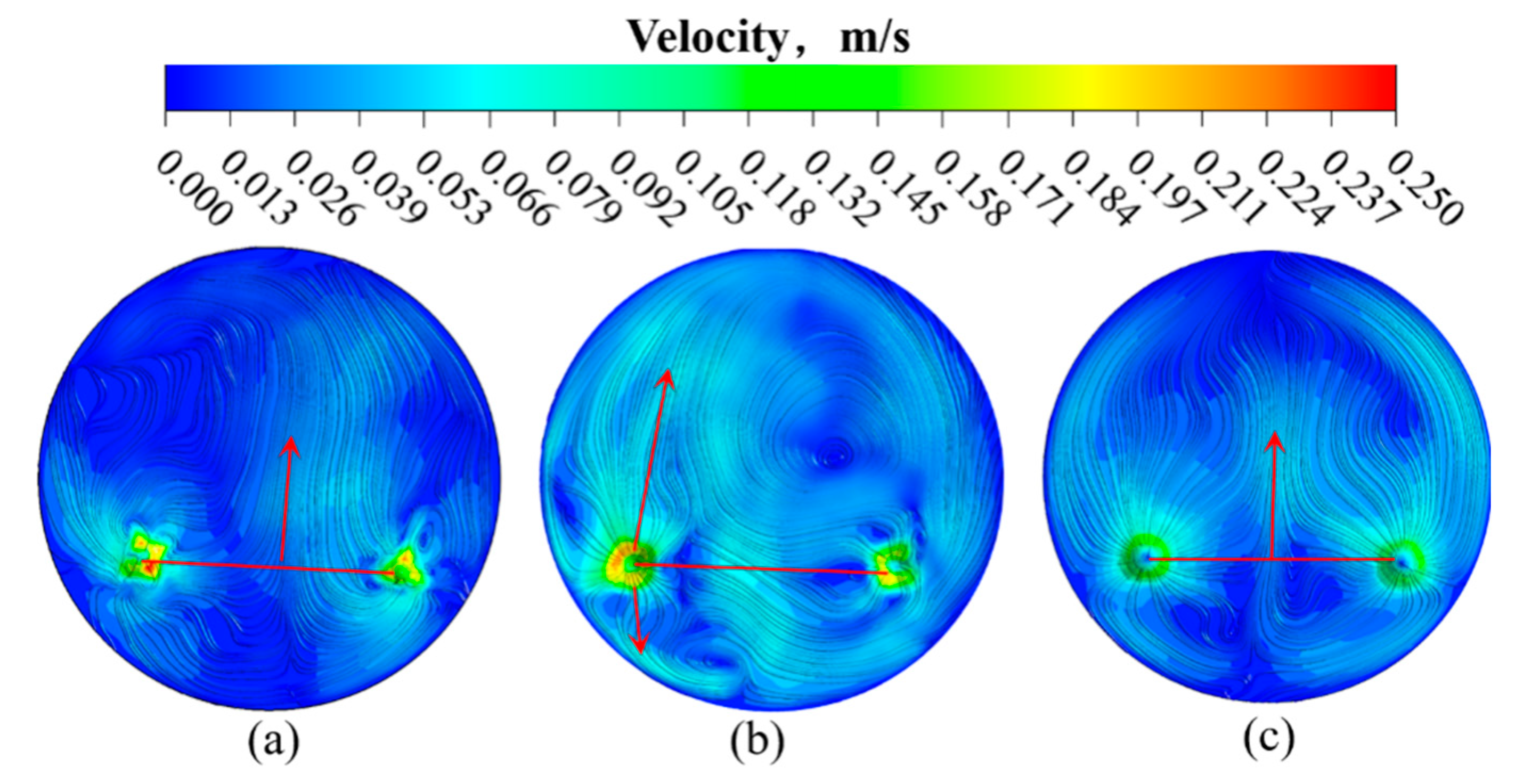
3.5. Flow Field and Velocity Distribution of Free Surface

Figure 11 shows the streamlines that were injected from two plugs. Obviously, when two plugs were of the same type (double slot or double porous plugs), the vortices were symmetrical about the center line of the ladle, as shown in Figure 11a,c. However, due to the fact that the kinetic energy induced by a slot plug was much higher than a porous plug, then the velocity induced along the slot side was higher than that along porous side, which can also be found in Figure 11b. This is why the vortex core along the slot side was higher than that on the porous side. When the vortices were symmetrical, the streamlines were mostly near to the top of the ladle. This may lead to the fact that the kinetic energy loss caused by symmetry flow was greater than that by the asymmetry flow. The reason for this phenomenon, as shown in reference [3,26], is because much of the energy loss was found near the free surface of the ladle. Comparing with Figure 11a,b, it can be seen that the streamlines caused by the slot-porous matched plugs were much lower than that by the double-slot plugs. A similar phenomenon was also shown in references [3,26]; however, different from their works, the injection rates in the two holes in our work were equal. As a result, the asymmetrical flow was mainly caused by using different plugs, rather than different flow rates. This is important for the inclusion removal since it can promote bubble distribution in the ladle. Similar streamlines are also found in Figure 11a,c, and this is why a similar phenomenon can also be found comparing with Figure 11b,c.
Figure 12 shows the velocity and streamlines on the free surface of liquid steel. Different plugs were selected to compare with each other. It can be seen from Figure 12 that, with the double slot type, the flow field was almost symmetrical with two plumes impinging on the center line of the surface. However, if one plug was replaced by a porous one, the streamlines were pushed towards the porous side. Additionally, if double porous plugs were adopted, the flow field was symmetrical, again to the center line of the ladle. The reason for these phenomena is because of the bubbles size distribution under different plugs.
Similar phenomena are also found in Figure 13, which shows the velocity and streamlines injected from two plugs. It can be seen from Figure 13 that the two vortices were formed after the gas was injected from the plugs, which was beneficial for the transportation of the alloy into the whole ladle. More importantly, due to the fact that the vortices were biased to the bottom due to velocity differences of the plugs, the mixing of steel was improved, as shown in Figure 13b, because the dead zone (the region with the velocity smaller than 0.01 m/s) was smallest among the other two. Therefore, it can be concluded that this new type of plug is beneficial for the mixing of molten steel.

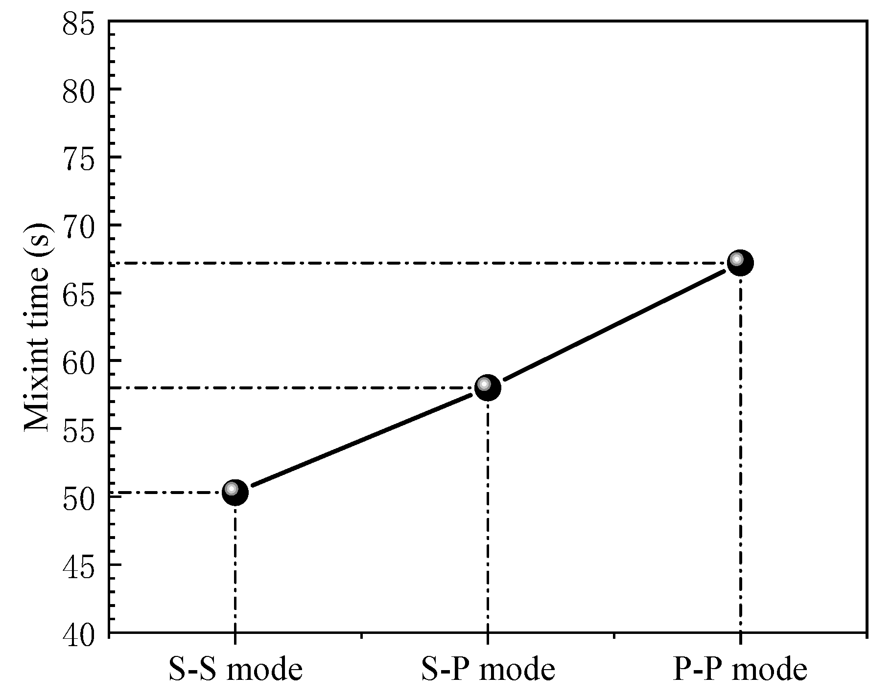
3.6. Mixing Time in Water Model

The mixing time of different plug arrangements are shown in Figure 14. The arrangement of experiment is shown in Figure 4a above. It can be seen from Figure 14 that, with a traditional type of two-slot plugs, the mixing time was about 50 s, while, after replacing with one porous plug, it was extended to about 58 s, which is about 16% longer than that of the traditional plugs. Additionally, after using two porous plugs, the mixing time reached a maximum at 67 s, which would deteriorate the fast mixing of molten steel and delay the process of continuous casting. Therefore, it is not suggested to be used in the current platform.

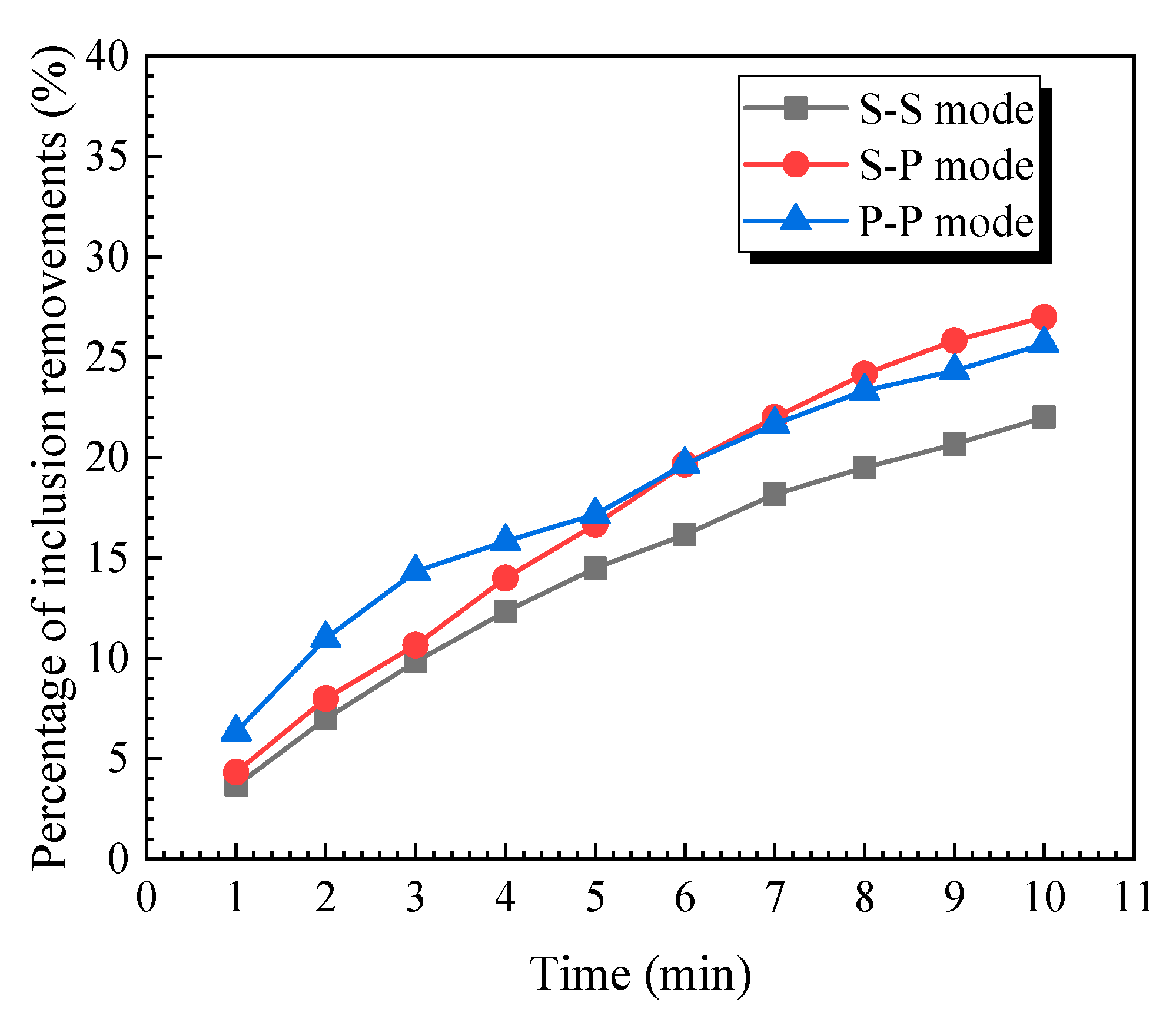
3.7. Transient Behavior for the Removal Ratio of Inclusions in the Ladle

The removement ratio in the water model was different under different flow fields, which can be seen in Figure 15. It can be seen that the removement ratio varied with time and mainly decreased with time. On the one hand, replacing one plug can increase the ratio of removement, while, on the other hand, the replacement may also stabilize the removement speed because the decline ratio is delayed. Overall, the replacement of a plug can significantly increase the ratio of inclusion removements.

4. Conclusions

In this work, a new method, which takes advantages of slot and porous plugs, was proposed to improve the cleanness in steel. A Water model and mathematical model were established to study the flow characteristics, mixing behavior, and inclusion removements in the ladle. The Main conclusions are as follows.
(1)
When using slot-porous plugs, the flow field is obviously asymmetrical and the circulations’ flow enlarges to the porous side. The removement of inclusions is 22.7% higher than traditional two-slot bottom stirring and homogenizes the flow field at the bottom of the ladle; however, the mixing time was delayed 16% comparing with traditional plugs.
(2)
The location of the recirculation flow is moved downwards after using slot-porous plugs and moves the recirculation flow downwards, which is helpful for homogenizing the flow at the bottom and promoting inclusion floating in steel.
(3)
The flow field is obviously asymmetrical after using a slot-porous ladle. The reason for this is because the bubble sizes are quite different with each other. The asymmetry flow field improves the mix ing behavior near the bottom of the ladle and, thus, deserves to be promoted.

Author Contributions

S.H. and D.W. conceived and designed the study. X.L. analyzed data and wrote the paper. T.Q. polished the language. Q.Q. and X.Z. helped analyze the data and gave suggestions for improving the work. G.W. helped to improve the theme of this work. P.Z. and Z.Z. helped to design and perform the water model experiment. All authors have read and agreed to the published version of the manuscript.

Funding

This work was financially supported by the National Natural Science Foundation of China (Nos. 51874203, 52174321, 52074186, 51974071 and 52104337), the Natural Science Foundation of Jiangsu Province: BK20200869 and the China Postdoctoral Science Foundation: 2020M681709.

Data Availability Statement

The data are not publicly available due to privacy.

Acknowledgments

The authors are grateful for the supporting of National Natural Science Foundation of China (Nos. 51874203, 52174321, 52074186, 51974071 and 52104337), the Natural Science Foundation of Jiangsu Province: BK20200869 and the China Postdoctoral Science Foundation: 2020M681709.

Conflicts of Interest

The authors declare no conflict of interest.

References

  1. Chen, M.; Wang, N.; Ya, Y.K.; Geng, J.L.; Xiong, K.X. Optimal mixing effect of LF bottom-blown stirring by two nozzles. Steel Res. Int. 2007, 78, 468–472. [Google Scholar] [CrossRef]
  2. Chen, Y.S.; Pang, Y.J.; Zhang, X.G. Numerical Study on Effects of Molten Steel Flow about Different Blowing Argon Position in Ladle Furnace. Adv. Mater. Res. 2010, 146, 1031–1037. [Google Scholar] [CrossRef]
  3. Tang, H.Y.; Guo, X.C.; Wu, G.H.; Wang, Y. Effect of Gas Blown Modes on Mixing Phenomena in a Bottom Stirring Ladle with Dual Plugs. ISIJ Int. 2016, 56, 2161–2170. [Google Scholar]
  4. Owusu, K.B.; Haas, T.; Gajjar, P.; Eickhoff, M.; Kowitwarangkul, P.; Pfeifer, H. Interaction of Injector Design, Bubble Size, Flow Structure, and Turbulence in Ladle Metallurgy. Steel Res. Int. 2019, 90, 90. [Google Scholar] [CrossRef]
  5. Tan, F.G.; He, Z.; Jin, S.L.; Pan, L.P.; Li, Y.W.; Li, B.K. Physical Modeling Evaluation on Refining Effects of Ladle with Different Purging Plug Designs. Steel Res. Int. 2020, 91, 1900606. [Google Scholar] [CrossRef]
  6. Zhang, L.F.; Thomas, B.G. Numerical Simulation on Inclusion Transport in Continuous Casting Mold. J. Univ. Sci. Technol. Beijing 2006, 13, 293–300. [Google Scholar] [CrossRef]
  7. Zheng, S.G.; Zhu, M.Y. Water Model Study on Removing Inclusions in a Ladle with Argon Injected through Nozzle and Porous Plug. Acta Metall. Sin. 2006, 42, 1143–1148. [Google Scholar]
  8. Wang, L.; Lee, H.G.; Hayes, P. Prediction of the Optimum Bubble Size for Inclusion Removal from Molten Steel by Flotation. ISIJ Int. 1996, 36, 7–16. [Google Scholar] [CrossRef]
  9. Liu, Z.Q.; Li, B.K.; Jiang, M.F. Transient Asymmetric Flow and Bubble Transport inside a Slab Continuous-Casting Mold. Metall. Mater. Trans. B 2014, 45, 675–697. [Google Scholar] [CrossRef]
  10. Johansen, S.T.; Robertson, D. Fluid Dynamics in Bubble Stirred Ladles: Part II. Mathematical Modeling. Metall. Mater. Trans. B 1988, 19, 755–764. [Google Scholar] [CrossRef]
  11. Mazumdar, D.; Guthrie, R.I.L. An Assessment of a Two Phase Calculation Procedure for Hydrodynamic Modelling of Submerged Gas Injection in Ladles. ISIJ Int. 1994, 34, 384–392. [Google Scholar] [CrossRef]
  12. Sheng, Y.Y.; Irons, G.A. The Impact of Bubble Dynamics on the Flow in Plumes of Ladle Water Models. Metall. Mater. Trans. B 1995, 26, 625–635. [Google Scholar] [CrossRef]
  13. Guo, D.; Irons, G.A. Modeling of Gas-Liquid Reactions in Ladle Metallurgy: Part II. Numerical Simulation. Metall. Mater. Trans. B 2000, 31, 1457–1464. [Google Scholar] [CrossRef]
  14. Duan, H.J.; Ren, Y.; Zhang, L.F. Effects of Interphase Forces on Fluid Flow in Gas-Stirred Steel Ladles Using the Eulerian–Lagrangian Multiphase Approach. JOM 2018, 70, 2128–2138. [Google Scholar] [CrossRef]
  15. Xie, Y.K.; Orsten, S.; Oeters, F. Behaviour of Bubbles at Gas Blowing into Liquid Wood’s Metal. ISIJ Int. 1992, 32, 66–75. [Google Scholar] [CrossRef] [Green Version]
  16. Liu, Z.Q.; Li, L.M.; Li, B.K. Modeling of Gas-Steel-Slag Three-Phase Flow in Ladle Metallurgy: Part I. Physical Modeling. ISIJ Int. 2017, 57, 1971–1979. [Google Scholar] [CrossRef] [Green Version]
  17. Li, L.M.; Li, B.K.; Liu, Z.Q. Modeling of Gas-Steel-Slag Three-Phase Flow in Ladle Metallurgy: Part II. Multi-scale Mathematical Model. ISIJ Int. 2017, 57, 1980–1989. [Google Scholar] [CrossRef] [Green Version]
  18. Li, L.M.; Liu, Z.Q.; Li, B.K.; Matsuura, H.; Tsukihashi, F. Water Model and CFD-PBM Coupled Model of Gas-Liquid-Slag Three-Phase Flow in Ladle Metallurgy. ISIJ Int. 2015, 55, 1337–1346. [Google Scholar] [CrossRef] [Green Version]
  19. Liu, Z.Q.; Niu, R.; Wu, Y.D.; Li, B.K.; Gan, Y.; Wu, M.H. Physical and Numerical Simulation of Mixed Columnar-equiaxed Solidification During Cold Strip Feeding in Continuous Casting. Int. J. Heat Mass Transf. 2021, 173, 121237. [Google Scholar] [CrossRef]
  20. Li, X.L.; Li, B.K.; Liu, Z.Q.; Niu, R.; Huang, X.C. Large Eddy Simulation of Electromagnetic Three-Phase Flow in a Round Bloom Considering Solidified Shell. Steel Res. Int. 2019, 90, 1800133. [Google Scholar] [CrossRef]
  21. Li, X.L.; Li, B.K.; Liu, Z.Q.; Niu, R.; Liu, Y.Q.; Zhao, C.L.; Huang, C.D.; Qiao, H.S.; Yuan, T.X. Large Eddy Simulation of Multi-Phase Flow and Slag Entrapment in a Continuous Casting Mold. Metals 2019, 9, 7. [Google Scholar] [CrossRef] [Green Version]
  22. Li, X.L.; Li, B.K.; Liu, Z.Q.; Niu, R.; Liu, Q.; Huang, X.C.; Xu, G.D.; Ruan, X.M. Detection and Numerical Simulation of Non-Metallic Inclusions in Continuous Casting Slab. Steel Res. Int. 2019, 90, 1800423. [Google Scholar] [CrossRef]
  23. Wang, C.J.; Liu, Z.Q.; Li, B.K. Combined Effects of EMBr and SEMS on Melt Flow and Solidification in a Thin Slab Continuous Caster. Metals 2021, 11, 948. [Google Scholar] [CrossRef]
  24. Wu, Y.D.; Liu, Z.Q.; Wang, F.; Li, B.K.; Gan, Y. Experimental investigation of trajectories, velocities and size distributions of bubbles in a continuous-casting mold. Powder Technol. 2021, 387, 325–335. [Google Scholar] [CrossRef]
  25. Li, X.L.; Li, B.K.; Liu, Z.Q.; Wang, D.Y.; Qu, T.P.; Hu, S.Y.; Wang, C.J.; Gao, R.Z. Evaluation of Slag Entrapment in Continuous Casting Mold Based on the LES-VOF-DPM Coupled Model. Metall. Mater. Trans. B 2021, 52, 3246–3264. [Google Scholar] [CrossRef]
  26. Jardón-Pérez, L.E.; González-Rivera, C.; Ramirez-Argaez, M.A.; Dutta, A. Numerical Modeling of Equal and Differentiated Gas Injection in Ladles: Effect on Mixing Time and Slag Eye. Processes 2020, 8, 917. [Google Scholar] [CrossRef]
Figure 1. Geometry for water model experiment.
Metals 12 00162 g001
Figure 2. Geometry model and boundary conditions: (a) isometric view, (b) top view.
Metals 12 00162 g002
Figure 3. Comparison of inclusion removements in water model through simulation and experiment.
Metals 12 00162 g003
Figure 4. Comparison of mixing time: (a) arrangement of injection position, detection point, and (b) comparison result.
Metals 12 00162 g004
Figure 5. Distribution of bubbles from slot plug: (a) 30 NL/min, (b) 150 NL/min, (c) 300 NL/min.
Metals 12 00162 g005
Figure 6. Distribution of bubbles from porous plug: (a) 30 NL/min, (b) 150 NL/min, (c) 300 NL/min.
Metals 12 00162 g006
Figure 7. Bubble distribution curve in the ladle with different plugs: (a) slot plug and (b) porous plug.
Metals 12 00162 g007
Figure 8. The characteristics of flow field with different bottom stirring mode traced by ink: (a) S-S mode, (b) S + P mode, and (c) P-P mode.
Metals 12 00162 g008
Figure 9. The characteristics of flow field with different bottom stirring mode traced by ink: (a) slot + slot plug, (b) slot + porous plug, and (c) porous + porous plug.
Metals 12 00162 g009
Figure 10. Bubble distribution with different bottom stirring mode: (a) S-S mode, (b) S-P mode, and (c) P-P mode.
Metals 12 00162 g010
Figure 11. Velocity and streamlines in the ladle with different plugs: (a) S-S mode, (b) S-P mode, and (c) P-P mode.
Metals 12 00162 g011
Figure 12. Velocity and streamlines on the free surface of liquid steel: (a) S-S mode, (b) S-P mode, and (c) P-P mode.
Metals 12 00162 g012
Figure 13. Velocity and streamlines in ladle with different plugs: (a) S-S mode, (b) S-P mode, and (c) P-P mode.
Metals 12 00162 g013
Figure 14. The Comparison of mixing time of bottom-stirring with different plugs (Arrangement for injection and detection point can be seen in Figure 4).
Metals 12 00162 g014
Figure 15. The Comparison of inclusion removements of bottom-stirring with different plugs.
Metals 12 00162 g015
Table 1. Geometry parameters and material properties.
ParametersReal LadleWater Model
Gas flow rate, NL/min150 + 1501.242 + 1.242
Plug angle °114°114°
Dynamic viscosity of steel, kg/(m·s)0.00510.001
Dynamic viscosity of air, kg/(m·s)1.79 × 10−51.79 × 10−5
Density of dioctyl phthalate, kg/(m3)2000~3000986
Radius of ladle bottom2717388
Publisher’s Note: MDPI stays neutral with regard to jurisdictional claims in published maps and institutional affiliations.

