Article

A Comparative Study on the Microstructures and Mechanical Properties of Al-10Si-0.5Mg Alloys Prepared under Different Conditions

1
School of Materials and Chemistry, University of Shanghai for Science and Technology, Shanghai 200093, China
2
Shanghai Metal Materials Near-Net-Shape Engineering Research Center, Shanghai Spaceflight Precision Machinery Institute, Shanghai 201600, China
*
Author to whom correspondence should be addressed.
Metals 2022, 12(1), 142; https://doi.org/10.3390/met12010142
Submission received: 1 December 2021 / Revised: 29 December 2021 / Accepted: 6 January 2022 / Published: 12 January 2022

Abstract

:
Fabrication condition greatly influences the microstructures and properties of Al alloys. However, most of the available reports focus on a single fabrication technique, indicating there is still a lack of systematic comparisons among wider ranges of fabrication methods. In this paper, with conventional casting (via sand/Fe/Cu mold) and additive manufacturing (AM, via selective laser melting, SLM) methods, the effects of cooling rate () on the microstructures and mechanical properties of hypoeutectic Al-10Si-0.5Mg alloy are systematically investigated. The results show that with increasing cooling rate from sand-mold condition to SLM condition, the grain size (d) is continuously refined from ~3522 ± 668 μm to ~10 μm, and the grain morphology is gradually refined from coarse dendrites to a mixed grain structure composed of columnar plus fine grains (~10 μm). The eutectic Si particles are effectively refined from blocky shape under sand/Fe-mold conditions to needle-like under Cu-mold conditions, and finally to fine fibrous network under SLM condition. The tensile yield strength and elongation is greatly improved from 125 ± 5 MPa (sand-mold) to 262 ± 3 MPa (SLM) and from 0.8 ± 0.2% (sand-mold) to 4.0 ± 0.2% (SLM), respectively. The strengthening mechanism is discussed, which is mainly ascribed to the continuous refinement of grains and Si particles and an increase in super-saturation of Al matrix with increasing cooling rate.

1. Introduction

With the increased requirements of the light-weighting function in the automotive, aeronautic and aerospace industries, light alloys, such as Al and Mg alloys, have exhibited more and more applications in these industries. Among many light alloys, the hypoeutectic Al-Si alloys are widely used as structural components. This is because Al-Si alloys exhibit low densities, low coefficients of thermal expansion, good casting properties, high strengths, high corrosion resistances, excellent wear resistances and good weldability [1,2,3]. The main alloying element, Si, increases the melt fluidity, reduces melting temperature and improves alloy properties.
To meet various application aims, Al alloys can be prepared through a number of techniques. In some cases, the conventional sand-casting method is adopted to prepare components with very large size and complex structures. In some other cases, the popular metallic-mold casting method is adopted to prepare components with small size and simple structure, which shows good dimensional accuracy and higher productivity. In addition to these, advanced non-equilibrium solidification techniques are adopted to produce high-strength Al alloys. For example, the rapidly solidified Al-12Si-1Mg alloy prepared with the melt spinning method shows a significant increase in hardness over the conventional castings [4], and the SLM as-built A356.0 alloy (Al-7Si-0.3Mg) shows superior mechanical properties to conventional castings [5]. In particular, when faced with the demands of extremely complex and precise structure and high-strengths, the SLM technique shows great potential in advanced manufacturing industries because the deposition mode of layer-by-layer plus track-by-track of powders is surprisingly flexible in producing cost-effective net-shape 3D objects [6]. Thus, it can be seen that the selection of preparation technique depends on the specific aim of engineering applications. Many factors, including the characteristic, property, productivity and cost should be considered during the method selection. In terms of materials development, it is important to make systematical comparisons among various preparation methods.
It is well known that during the preparation process, the solidification conditions have major influences on the alloy properties. For example, during traditional sand-mold casting and gravity casting processes, if the casting component itself is too large and complex, the cooling rate () may vary among different locations with diverse thickness. A slower cooling rate produces coarse microstructures and lower mechanical properties, while a faster cooling rate produces finer microstructures and higher mechanical properties [3,7]. Thus, the variations in cooling rate among different locations may induce the microstructural inhomogeneity and composition segregations, which causes the non-uniformity in mechanical properties. For another example, during AM, the special cooling and thermal cycle may produce fine microstructure but always with uniform distributions and residual stress inside. Therefore, it is quite significant to establish the relationships among cooling condition, microstructure and mechanical properties of Al-Si alloys.
So far, there are many reports available on the comparisons of microstructures and/or properties among Al-Si alloys fabricated with different methods [2,7,8,9,10,11,12]. For instance, Fathi et al. [8] compared the microstructure of SLM Al-10Si-0.5Mg alloy die-cast Al360.1 alloy, showing that SLM alloy has a very uniform distribution of fine Si particles without formation of any intermetallic, which improves the corrosion resistance. Yan et al. [10] found that the SLM Al-10Si-0.5Mg alloy showed higher tensile strength but lower elongation than casting counterpart due to grain refinement and tortuous crack path. However, most reports focus on two kinds of fabrication methods, which is inadequate for practical engineering applications that always include much wider ranges of solidification condition. There is still a lack of systematic comparisons within a wider range of conditions. Based on the above background, the present study investigates the Al-10Si-0.5Mg alloys fabricated under four representative cooling conditions, including sand/Fe/Cu-mold casting and SLM. This paper will supply useful guidance for practical engineering application.

2. Materials and Methods

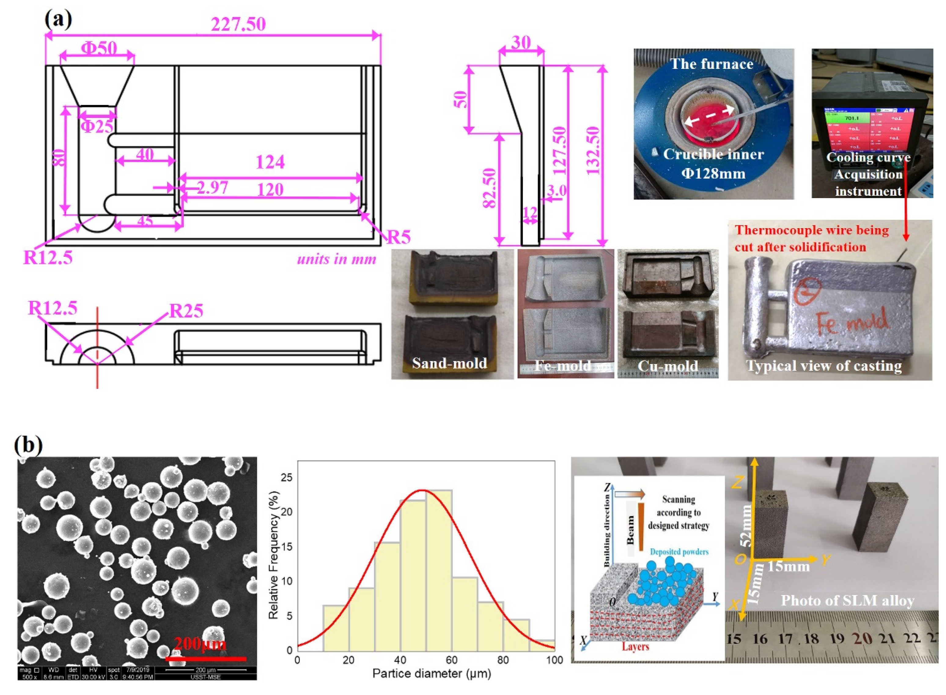
2.1. Alloy Fabrication

When a small fraction of Mg element is added to Al-Si alloy, the mechanical properties can be obviously improved by the tiny Mg2Si precipitates formed during aging treatment [13]. Therefore, the ternary Al-Si-Mg alloy was selected as the typical alloy in the study. Table 1 shows the actual chemical compositions (in wt.%) of Al-10Si-0.5Mg alloys measured via Inductive Coupled Plasma Atomic Emission Spectroscopy (ICP-AES) analysis. It is noted that the Mg content of Al-10Si-0.5Mg powder is much lower (~0.26 wt.%), which is possibly due to the evaporation loss during high-temperature preparation.
Conventional casting and advanced SLM techniques were adopted with the following details:
(i) Conventional casting process. To avoid the composition deviations between different castings, the sand/Fe/Cu-mold castings were fabricated with the same batch of alloy melt. The electric resistance furnace (SG2-3-10, Shanghai Shiyan Electric Furnace Company Ltd., Shanghai, China) with a stainless-steel crucible (inner diameter 128 × height 220 × thickness 6 mm3) was used for melting. Before melting, the internal surface of crucible was coated with a coating composed of talcum powder, sodium silicate and water in order to prevent the melt contamination by iron impurity. The coating was dried during preheating the crucible.
Five kilograms of Al-10Si-0.5Mg alloy were melted from raw materials of pure Al (99.8 wt.%), Al-20 wt.% Si (impurity Fe < 0.16 wt.%) and pure Mg (99.7 wt.%). 0.2 wt.% TiB2 grain refiner was added in the form of Al-5 wt.% Ti-1 wt.% B master alloy rod, and 0.02 wt.% Sr modifier was added in the form of Al-10 wt.% Sr master alloy rod. It is noted that the most popular grain refiner is the Al-Ti-B master alloy [14]; the modifiers for Si phase include P [15], Na [16], Sr [17], Ce or Sb [18], among which Sr shows a better effect. The melt was poured at about 700 °C into a sand-mold (200 °C), Fe-mold (200 °C) and Cu-mold (room temperature to get a good cooling effect) with the same dimension as shown in Figure 1, respectively.
During solidification, the cooling curve (Figure 2) was collected with a temperature acquisition system (YADU700R, Shanghai Yadu Instrument, Shanghai, China) whose acquisition frequency 10 data points per second and accuracy ± 0.1 °C. Before pouring, the K-type thermocouple wire (Ø 0.5 mm) connected with the system was placed at the 10-mm depth of mold shown in Figure 1a. The K-type thermocouple was inserted neither in the pouring gate nor in the bottom part of the mold, which aimed to prevent destroying the casting body. The pre-solidification cooling rate was calculated among the temperature range from 700 °C to 590 °C (liquidus temperature according to reference [19]), which gave the pre-solidification values as 3.5 °C/s under sand-mold condition and 12.5 °C/s under Fe-mold conditions, respectively. However, for the Cu-mold casting, the cooling rate was really difficult to measure because of its fast cooling effect. The pre-solidification cooling rate for Cu-mold was estimated to be ~80 °C/s according to our previous study [20].
(ii) SLM process. A 3D printing machine (German EOSINT M280, Krailling, Germany) was employed to build Al-10Si-0.5Mg alloy. The new commercial gas-atomization Al-10Si-0.5Mg powder (Tekna Ltd., London, UK) was used (Figure 1b), which had spherical morphology with diameters mostly ranging from 20 to 60 μm. The ingot employed for the gas-atomization process was grain-refined by Al-Ti-B refiner. The building parameters were laser power 275 W, scanning velocity 1000 mm/s, hatching space 0.08 mm, layer thickness 0.03 mm and substrate plate ~80 °C. Between consecutive layers, the rotation angle of scanning route was 67°. The size of SLM Al-10Si-0.5Mg block was length 15 × width 15 × height 52 mm3. The accurate value of cooling rate under SLM was not known; but according to reference [21], it normally reaches 106~108 °C/s level. The building direction is defined as Z axis. The microstructures of SLM sample were observed along both longitudinal direction (i.e., vertical, YOZ equal to XOZ) and transverse direction (i.e., horizontal, XOY), as shown in Figure 1b.
It is known that the residual stress is often formed in SLM alloys, which requires the subsequent stress relief step [22]. However, at the current stage, SLM samples were not subjected to stress relief (although it would be simple), in order to compare under the same state (i.e., before heat treatment). The influence of stress relief and heat treatments on the microstructures and mechanical properties will be investigated in a future study.

2.2. Characterization and Analysis

The specimens for X-ray diffraction (XRD) phase identification were prepared through metallographic grounding and polishing procedures. XRD pattern was acquired on a Bruker D8 Advance diffractometer (Billerica, MA, USA), using the Kα emission line of a Cu filament (λCu = 1.5418 Å), within the 2θ range from 20° to 90° at 0.02° step. The specimen for microstructure observation was prepared through standard metallographic procedures, including grounding, polishing and etching. The etchant was Keller reagent composed of 2.5 mL of HNO3, 1.5 mL of HCl, 1 mL of HF and 95 mL of H2O. The samples were etched at room temperature for 10 s. The microstructures were observed with both optical microscope (Zessis A1, Oberkochen, Germany) and scanning electron microscope (FEI Nova NanoSEM 230 (Lincoln, NE, USA)) equipped with energy dispersive spectrum (EDS) detectors. 3D microstructure distribution of SLM alloy was simply shown through combining OM or SEM images observed along different directions.
In order to measure average grain size as well as “secondary dendrite arm spacing (SDAS, λ2, reflecting the local conditions for heat extraction during solidification)” for sand/Fe/Cu-mold Al-10Si-0.5Mg castings, the polished samples were electrochemically anodized in Barkers’ reagent (4 vol.% HBF4 water solution) at room temperature with 20 V for 60 s and then observed under polarized light mode with optical microscope. Using at least five polarized light images with low magnification, the average grain size and SDAS was measured through the linear intercept method according to ASTM E112-96. For the SLM alloy, electron backscatter diffraction (EBSD) was conducted along the longitudinal direction with Oxford HKL detector (Abington, UK) equipped to the SEM, which reveals the grain structure and size distribution. In addition, the SDAS of SLM alloy could not be measured because the SLM Al-10Si-0.5Mg alloy did not show dendrite morphology.
Si particle distribution in conventional Al-Si cast alloy were measured to reflect the refinement behavior. The area percentage of Si phase with each “main/major length (Lm)” range was counted using an image analytical software. The Lm is already defined by the software, indicating a Feret diameter (or Caliper length) along the major axis of the object. The main steps for counting include calibration of the scale bar, analysis and measurement, exporting measurement data to Microsoft EXCEL, classification and counting using the COUNTIFS function, calculation and plotting. Because in the microstructure, the Si sizes mostly seemed to be larger than 5 μm, the measurement data below 5 μm were regarded as the noisy points (such as small inclusions) and then eliminated. For each alloy, five optical images with 200× (magnification) were used for counting, where more than 200 Si particles could be analyzed. However, The Si distribution in SLM alloy was not measured due to a continuous network-distribution.
The samples for tensile property tests (Figure 3, reproduced from reference [23]) were cut with electric-spark wire-cutting machine. Note that the sample of SLM alloy was cut along the vertical direction (Z). The tensile testing was conducted on a Zwick/Roell-50 KN material test machine (Ulm, Germany) at a cross-head speed of 0.5 mm/min at room temperature. For each alloy, five parallel specimens were tested to calculate average values and standard deviations for yield strength (YS, MPa), ultimate tensile strength (UTS, MPa) and elongation to failure (EL., %).

3. Results

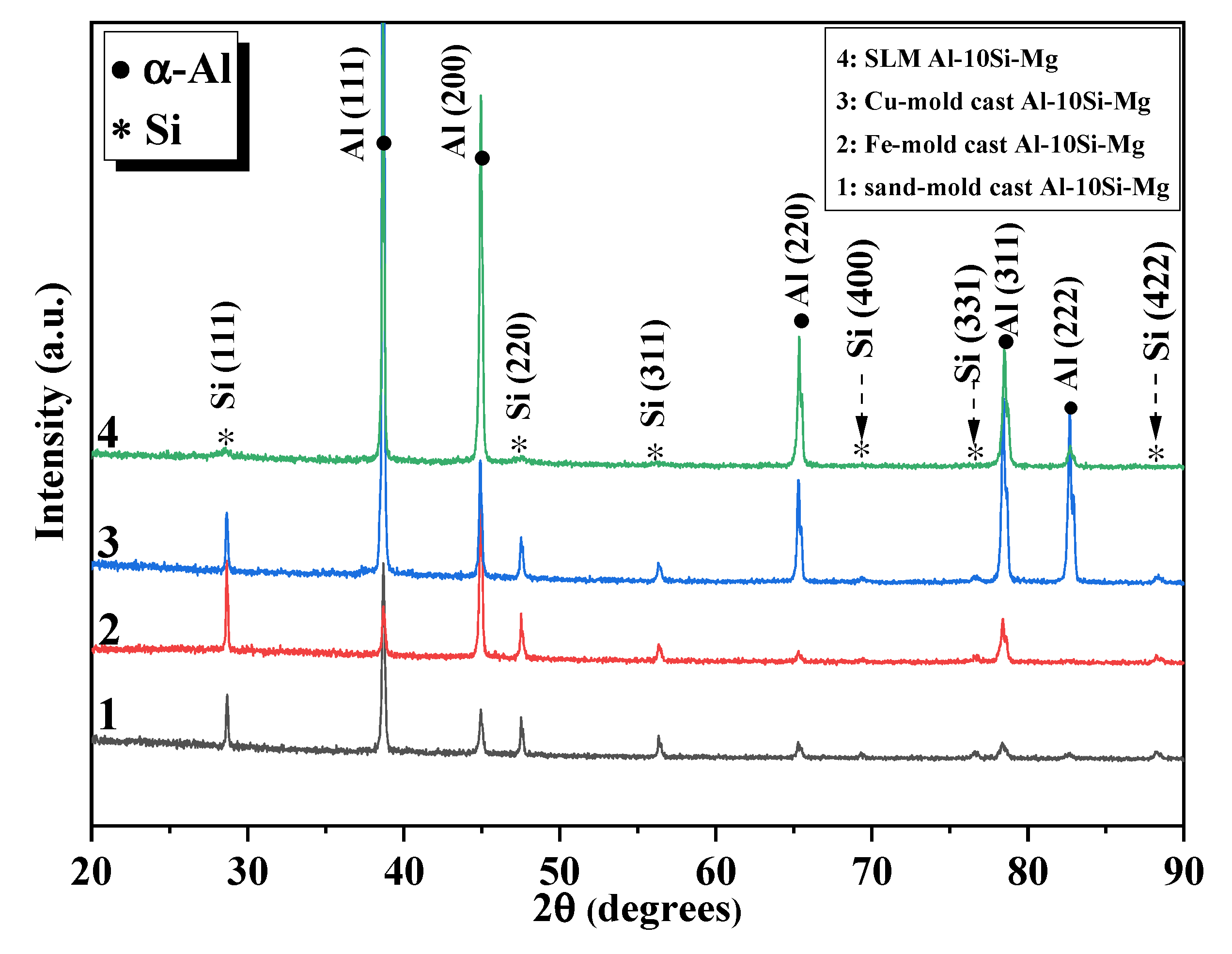
3.1. Phase Constitutions

Figure 4 shows the phase constitutions identified by XRD. It can be seen that the main phases are composed of face-centered cubic (FCC) α-Al and diamond cubic β-Si, which agrees well with the binary Al-Si phase diagram [22]. Moreover, the diffraction peak intensities of Si phase in the SLM alloy are much weaker than that in the other three alloys, and even the Si (400), (331) and (422) peaks vanish as indicated by the dashed arrows. This is mostly due to the non-equilibrium solidification effect during SLM process. The super-saturation degree of Si element in the Al matrix is improved during SLM [24]. This effect decreases the amount of eutectic Si and the subsequent diffraction peak intensities. The super-saturation of Al matrix can supply a solid-solution strengthening effect.
In the ternary Al-10Si-0.5Mg alloy, the Mg2Si phase should exist. However, Mg2Si phase was not detected in Figure 4 due to a low content of Mg (~0.5 wt.%). Despite this, the influences of small Mg content on the solidification behavior cannot be neglected.
(1) According to the Al-Si binary phase diagram, the solidification process of hypoeutectic Al-Si alloy comprises of two main stages: 1st nucleation and growth of Al dendrites and 2nd nucleation and growth of Al + Si eutectic. When the solidification begins below the liquidus (~600 °C for Al-10Si), the α-Al dendrites nucleate and grow with orthogonal arms. The continuous growth of α-Al phase causes a continuous increase in the Si concentration in the residual liquid. When the Si concentration increases to the critical value “eutectic point 12.6 wt.% Si” (at 577 °C), the liquid phase transforms into the eutectic phase composed of Al + Si [22]. The Si phase grows along the stable close-packed plane {111} [25], making this peak more obvious than other peaks in Figure 4.
(2) When 0.5% Mg element is added, the liquidus temperature can be decreased by 1~3 °C [26], and the solidification behavior can be influenced. Under non-equilibrium solidification, the ternary eutectic reaction L → Al + Si + Mg2Si at ~555 °C exists [26,27]. Thus, the eutectic phases contain a small amount of Mg2Si phase. However, it is also reported that when Sr modifier was added, the nucleation of Mg2Si was severely restrained and only very few tiny Mg2Si particles were formed at the eutectic network boundaries [27]. This is probably one of the main reasons why the Mg2Si phase was hard to detect in the Sr-modified Al-10Si-0.5Mg alloy.

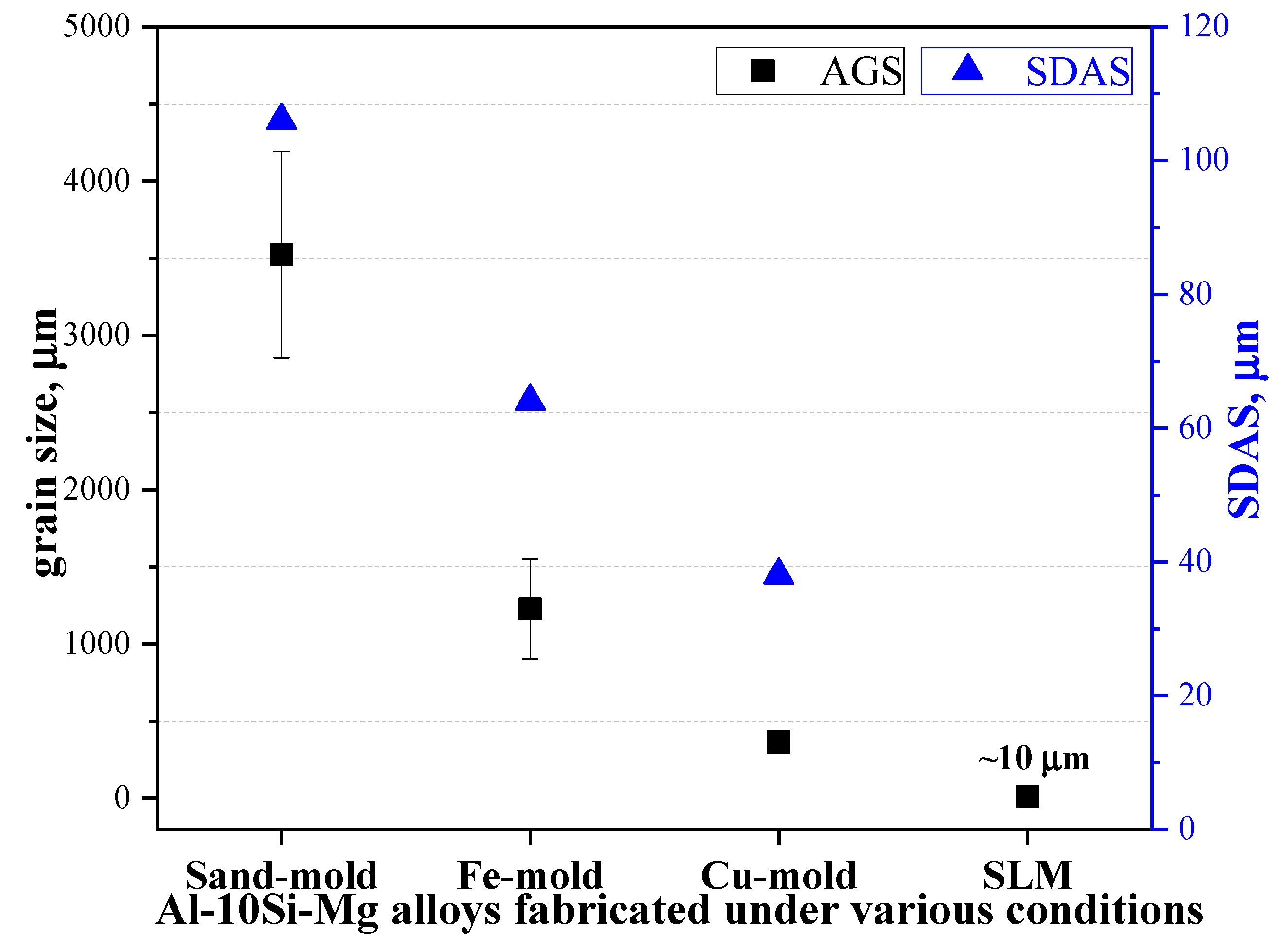
3.2. Grain Morphology and Grain Size

Figure 5 shows the optical microstructure of alloys. The variations in average grain size and SDAS (λ2) are plotted in Figure 6. The average grain size of alloys cast with sand-mold and Fe-mold is ~3522 ± 668 μm and ~1227 ± 324 μm, respectively, showing very coarse grains with obvious inhomogeneity (with large error bars). However, with continuous increase in cooling rate, the grains are remarkably refined from coarse dendrite to finer grain (~365 ± 36 μm of Cu-mold casting) and finally to a mixed grain structure composed of columnar and fine grains (~10 μm of SLM alloy, similar to the value in reference [28]).
Due to the special forming route of SLM, the microstructure along different directions have obvious differences. Within the XOY plane (Figure 5d), the microstructure displays the “elongated or columnar tear-drop shape” feature. The average width of the tear-drop cell is measured as approximately 100 μm, which corresponds to the melt pool (MP) during the SLM process. The principal direction of “tear-drop” corresponds to the laser scan direction, and the angle (67°) changes between consecutive layers according to the rotation angle in laser scan strategy [7]. Within the XOZ plane, the molten pools exhibit the overlapped semi-circular fish-scale-like morphology with average depth of 110 μm (Figure 5e). This kind of “columnar + fish-scale” feature in SLM alloys is caused by the unique laser energy field and “track after track + layer after layer” mode of material deposition [29].
The formation mechanism of fish-scale morphology is mainly because of the Gauss energy distribution of the laser beam. The energy density in the center is higher than at the edge of laser beam [30,31]. A temperature gradient can be formed in the longitudinal profile of molten pool of Al-10Si-0.5Mg alloy, where the temperature in the center of MP is much higher than at the edge. Then, the liquid surface tension gradient can be formed in the molten pool. Thus, the Marangoni convection effect is formed, where the liquid metal can flow from the center to the edge of the molten pool along the radial direction, forming the fish-scale morphology after solidification.

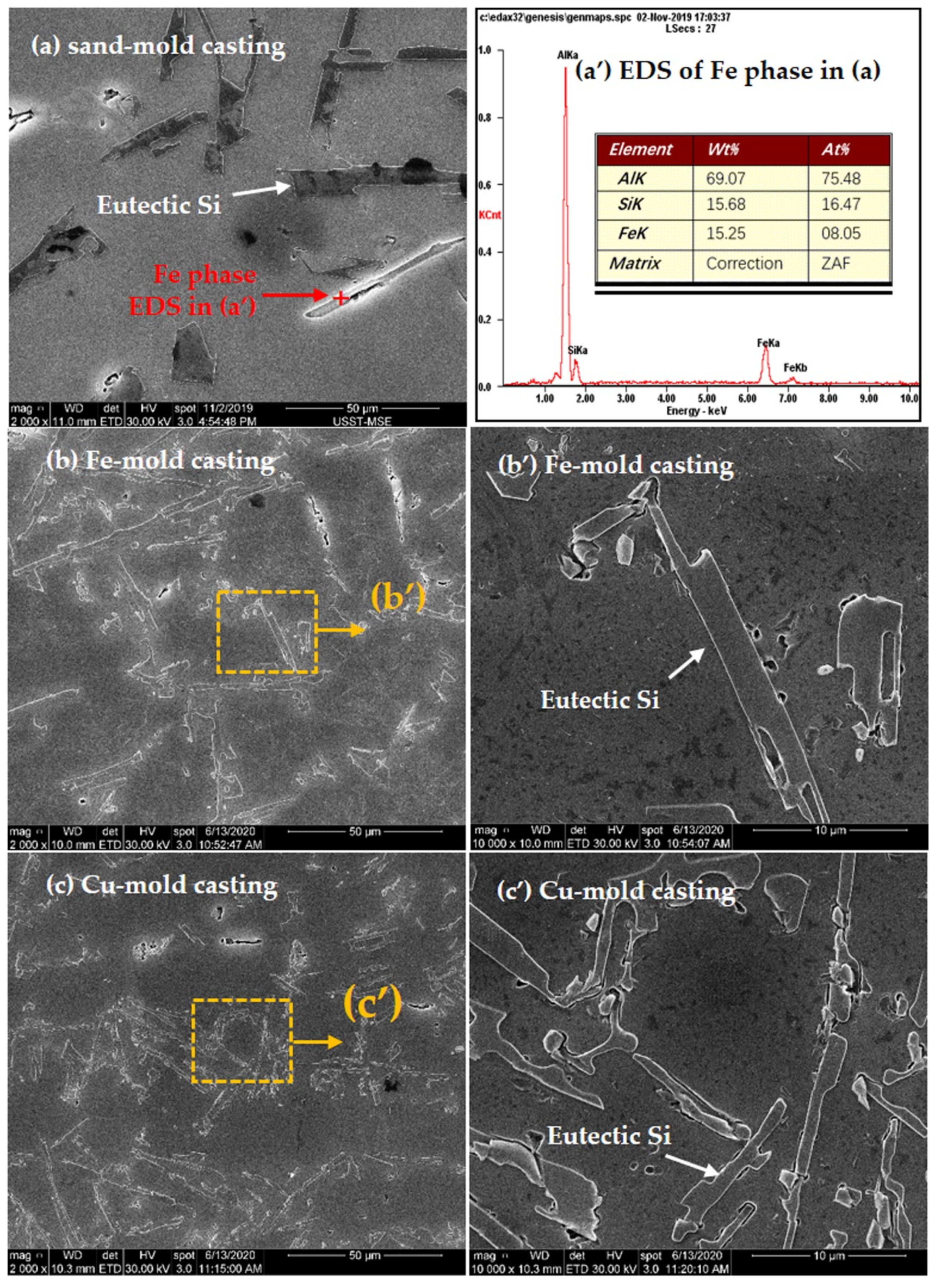
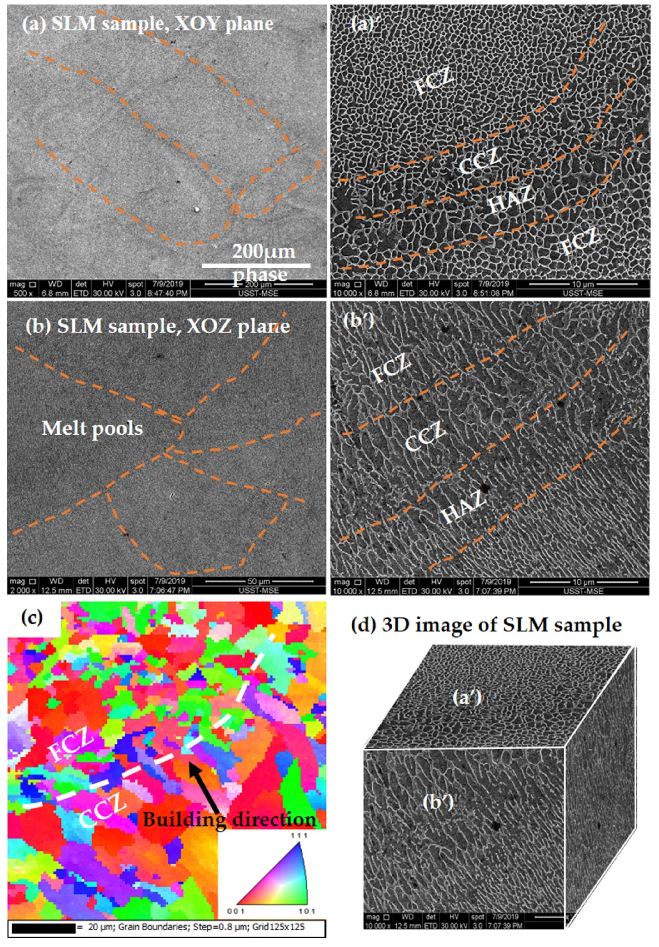
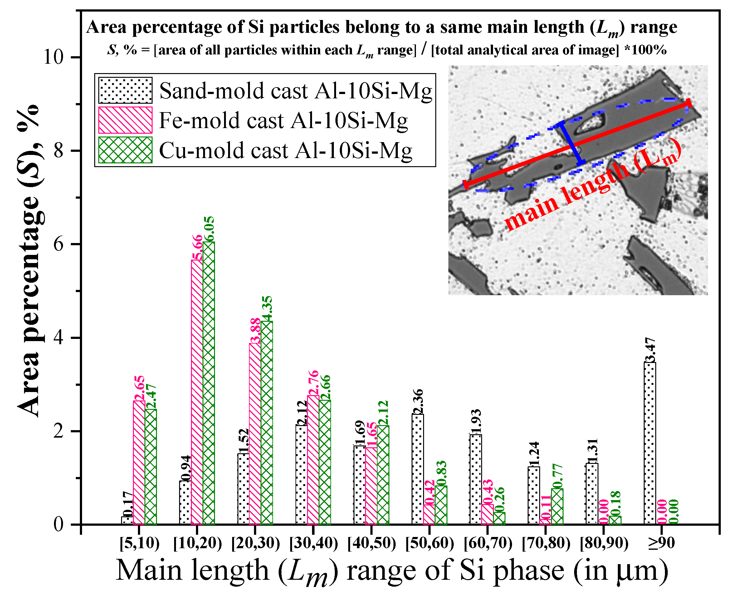
3.3. Microstructures

Figure 7 shows the SEM microstructures of conventional cast alloys, where Figure 7b is the typical EDS result of the Fe-rich particles that present in the sand-mold cast alloy. It can be seen that all the three alloys are composed of α-Al and Al + Si eutectic phases, but the morphology of Al + Si eutectic is varied, with an increase in cooling rate. For the sand-mold and Fe-mold castings (Figure 7a–b’), most of the Si particles show blocky shape (or called “flakes”). With an increase in the cooling rate to Cu-mold, the Si particles are obviously refined to be narrower and shorter rods (i.e., needle-like).
Moreover, the Fe-rich compound marked with red arrow in Figure 7a shows the platelet-like phase with length above 50 μm. Lu and Dahle showed that the quantity, size and morphology of the Fe-rich intermetallic phase could be strongly influenced by not only contents of Fe, Mn and Mg elements, but also melting conditions, including cooling rate, Sr modification and superheating [32]. Normally, slow cooling rate favors the formation of the β-Al5FeSi phase, while Al15Fe3Si2 phase forms in some other cases [10,32]. The β-Al5FeSi phase always shows platelet-like shape [9]. Therefore, the Fe-rich phase in sand-cast Al-10Si-0.5Mg alloy is deduced to be the β-Al5FeSi phase.
Figure 8 shows the SEM and EBSD microstructure of SLM Al-10Si-0.5Mg alloy, where Figure 8a,a’ is along the longitudinal direction, Figure 8b–c is along the transverse direction, Figure 8d is the 3D morphology constructed with the SEM images under 10,000× magnification. Figure 8a’,b’ clearly display the alternate microstructure consisting of three repeated zones across the melt pool (MP), i.e., the network fine-cellular zone (FCZ) growing toward the center of MP, the network coarse-cellular zone (CCZ) forming at the MP borders (MPBs) and the heat affected zone (HAZ) showing the slightly broken formation of the Si network in the previous track near the overlaps as a result of laser overheating [29,33]. This kind of “three zones” structure mainly results from the different local thermal gradient histories [10,33]. However, each zone was not further characterized in detail here because the present work mainly focuses on the comparisons between various fabrication conditions rather than the SLM alloy itself. In addition, no Fe-rich phase was observed in SLM alloy because of a fast cooling effect and a relatively lower impurity Fe content (~0.14 wt.%) in the original powders. In addition, it is reported by Yan et al. [10] that the Fe-rich phases formed under SLM nonequilibrium solidification condition was identified by transmission electron microscopy (TEM) as tiny π-Al8Si6Mg3Fe phase rather than the lamellar β-Al5FeSi phase that formed under slow cooling. However, in the present study, the π-Al8Si6Mg3Fe was not characterized, which requires further TEM observations.
Compared with Figure 7, it can be seen that the shape of Si particles were totally converted to an ultrafine fibrous network (or called “coral-like”) without any blocky or needle-like rods (Figure 8a’,b’). This kind of fibrous distribution of eutectic is due to the typical solidification process during SLM, where the large temperature gradient induces a highly undercooling condition. Si particles partially segregate on the columnar grains of the α-Al phase as fibrous particles that “decorated” the primary α-Al grains. Thijs et al. defined this kind of distribution as “intercellular network” [29]. In the present study, the average size of Si cell was measured as about 650 nm, which is quite similar to the size value (600~800 nm) reported by Wei et al. [30]. Moreover, it is expected that the small Si precipitates with ~50 nm size also exist in the Al cells [34], which need transmission electron microscope (TEM) work.
Figure 8c further shows the EBSD grain structure of a selected area in SLM Al-10Si-0.5Mg alloy along the longitudinal direction (Z). Based on Figure 8b’,c, it can be easily inferred that each grain is actually composed of lots of cells. The grain size shows a nonuniform distribution, i.e., the fine grains are of ~10 μm level while the columnar grains grow to longer than 100 μm. The color legend indicates that columnar grains tends to grow along <001> orientation and forms a strong <001> texture. This is because face-centered cubic (FCC) Al preferentially grows along the <001> crystal direction. More importantly, no grain refiner was added during the SLM process of Al-10Si-0.5Mg alloy. The undercooling at the solid/liquid (S/L) interface is insufficient to surpass the critical nucleation undercooling for heterogeneous nucleation, which favors the columnar grains growing along the heat flow direction within the MP [10]. It is expected that if the suitable grain refiner is added during SLM, the columnar grains can be transformed into equiaxed grains, and the <001> texture would be much weaker. For example, when 0.5 wt.% LaB6 nanoparticle was added in Al-10Si-0.5Mg alloy powder, the SLM alloy exhibited refined equiaxed grains with ~2-μm size and random orientation (almost textureless structure) [35].
Figure 9 shows the area percentage (S, %) of each main length (Lm) range of Si phase in conventionally cast alloys. It can be seen that within the Lm ranges (5, 10), [10, 20), [20, 30) or [30, 40), the area percentage of Si particles in sand-mold cast alloy is much lower than that in Fe-mold and Cu-mold cast alloys, while within the Lm ranges [50, 60), [60, 70), [70, 80), [80, 90) or >90, the area percentage in sand-mold cast alloy is much higher than that in Fe-mold and Cu-mold cast alloys. These results indicate that the sand-mold cast alloy has a lower number of fine Si particles (but more large Si particles) than Fe-mold and Cu-mold castings. In other words, the Si rods or plates are gradually refined to be shorter and narrower needle-like ones with increasing cooling rate. However, even in the Cu-mold casting, most of the Si particles has Lm sizes between 10 and 30 μm, which is detrimental to the mechanical properties due to their needle-like morphologies. When it comes to SLM alloy, although no size data is available for Si particles, the distribution of tiny Si cells is thought be better (Figure 8).

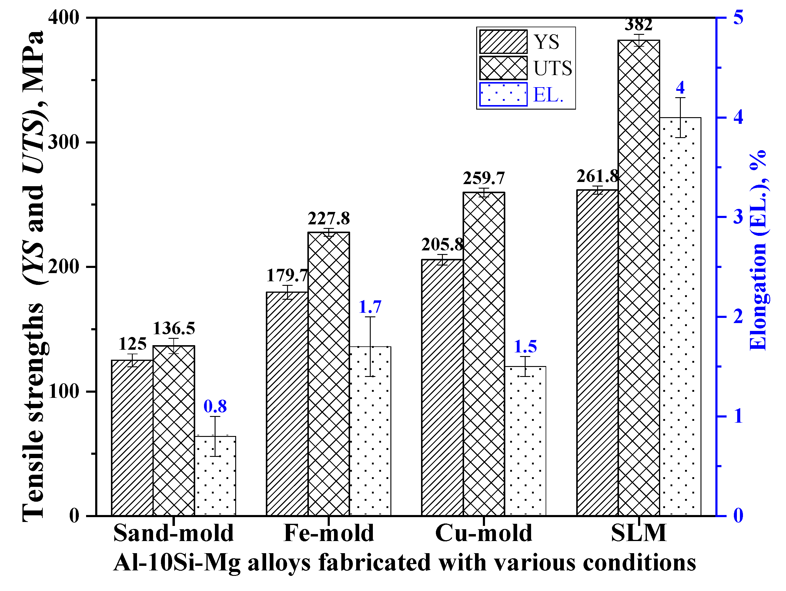
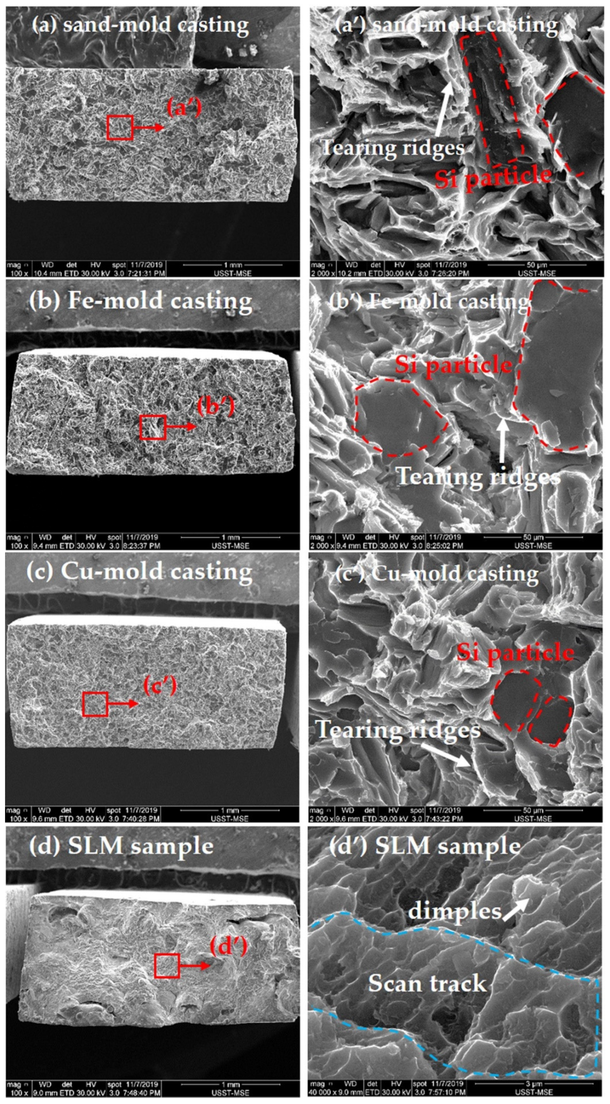
3.4. Tensile Mechanical Properties

Figure 10 shows the tensile properties of the four alloys. It can be seen that, with increasing the cooling rate, the mechanical property is gradually improved. The SLM Al-10Si-0.5Mg alloy shows the best mechanical properties, i.e., YS 262 ± 3 MPa, UTS 382 ± 5 MPa and EL. 4.0 ± 0.2%, respectively. The improvement in yield strength and elongation is mainly attributed to the microstructure refinement effect, which will be carefully explained in the Discussion section.
Figure 11 shows the fractographies of Al-10Si-0.5Mg alloys prepared under different conditions, where the right column images show the corresponding high magnification morphology for the selected rectangular regions in low magnification images in the left column. The sand-mold, Fe-mold and Cu-mold cast alloys mainly exhibit lots of tearing ridges, showing brittle fracture mode. The fractured Si particles can be seen under sand/Fe/Cu-mold conditions as indicated by the dashed line boxes in Figure 11a’–c’, which agrees well with the typical fracture feature of conventional Al-Si alloy casting [36]. During the tensile damage process, Si particles with large size destroy the continuity of Al matrix, being detrimental to the mechanical property. These particles firstly crack or debond, then the micro-cracks form and grow in the cracked or debonded Si particles, and finally the micro-cracks link and factures occur [37]. In contrast, for the SLM alloy, lots of submicron-sized fine dimples are found in Figure 11d’, indicating the ductility is sharply improved, i.e., the elongation increases from 0.8 ± 0.2% to 4.0 ± 0.2%. It is shown that the fracture in SLM alloy initiates along the dendrite cell network, because the Si-enriched network has a higher hardness but a lower ductility compared to the Al-enriched cells [38]. Additionally, the shape of laser scan tracks remains as shown in Figure 11d’, which is the typical morphology of fractured SLM alloy [32].

4. Discussion

4.1. Microstructure Evolutions

Figure 5 and Figure 6 show that the grain morphology of conventional sand/Fe/Cu-mold cast Al-10Si-0.5Mg alloys is mostly coarse dendrites, while that of SLM Al-10Si-0.5Mg alloy is mainly converted to much finer grains (although there still exists columnar grains). It has been reported that the grain structure and size are mostly influenced by the interactions between thermal gradient (G, K/m) and solidification rate (R, m/s) at the solid/liquid interface [39]. The ratio of G/R determines the solidification mode, while the product of G × R (i.e., cooling rate , K/s) determines the grain size. The effect of preparation method on the grain morphology and grain size can be understood as follows.
(1) Grain morphology. Generally, a smaller G/R value benefits to forming equiaxed grains due to the creation of a larger amount of undercooling that facilitates a nucleation event [34]. With the progressive decrease in G/R, the grain morphology evolves from planar to cellular, columnar and an equiaxed crystal [22,29].
In this study, with the preparation method changing from sand-mold to Fe-mold then to Cu-mold, G successively increases, but R increases much faster. These changes make G/R value decrease continuously and the grain structure change from dendrite to equiaxed grain (Figure 5a–c). For the SLM alloy, G within the MP is higher (perhaps ~107 K/m [35]) than that in conventional casting (about 10–103 K/m). A higher G seems to cause epitaxial growth along the heat flow direction and form columnar grains, which is the reason why columnar grains that grow toward upper centers of the MP along the laser building direction are always observed in SLM alloys. However, compared with the conventional casting method, the SLM process also has a high solidification rate R due to the ultra-fast cooling effect [35]. A lower G/R value can also be yielded, which leads to cellular grains in SLM alloy (Figure 5e) [35]. Moreover, due to the non-equilibrium solidification effect during SLM, the kinetics to form Si eutectic is decreased to some extent, which makes residual Si form an interconnected network along the boundaries of α-Al cells [40,41].
The empirical relationship Equation (1) exists between SDAS (λ2) and cooling rate () [16,42]:
λ 2 = A T ˙ 1 / 3
where A is a fitting factor. The values of pre-solidification cooling rate were 3.5, 12.5 and 80 °C/s, respectively, as indicated in Section 2.1. In the present study, because the sand/Fe/Cu-mold cast Al-10Si-0.5Mg alloys show obvious dendrite features, the SDAS of these three alloys were measured as shown in Figure 6 and well fitted as Equation (2), where regression coefficients (R) are as high as 0.99:
λ 2 = 153.8 T ˙ 0.32   ( R 2 = 0.99 )
This relationship indicates that the SDAS of Al-10Si-0.5Mg alloy can be progressively refined with increasing cooling rate (). It has been reported that although non-dendritic or cellular structure is formed under high cooling rates, the grain or cell size acts in the same capacity as SDAS at lower cooling rates and obeys the same dependency on the cooling rate [43]. However, due to the lack of accurate values of cooling rate under SLM, the grain size was not fitted with cooling rate in Figure 6. Nevertheless, using Equation (2), the cooling rate of SLM can be inversely estimated to be at 104 order of magnitude.
(2) Grain size. It is well known that the grain size during solidification is influenced by nucleant particles, solute element content and cooling rate [44,45,46]. Suitable nucleant particles provide heterogeneous nucleation sites for primary solid phase; solute elements provide constitutional supercooling (CS) to restrict grain growth and facilitate further nucleation events [44,45]; cooling rate influences growth velocity and temperature gradient [45]. Equation (3) relates the grain size (d) to factors, including grain restriction factor (GRF, Q) caused by solute content, potency of nucleant particles (“b”), number density of nucleant particles (“a”) and cooling rate () [46]:
d = a + b Q T ˙
In Equation (3), a larger number of activatable nucleants provides a smaller “a” value; a higher nucleation potency of particle provides a lower “b” value; and a higher solute content provides a higher Q value [44,45]. According to Equation (3), under normal conditions, such as sand-casting, pure Al shows that the coarse grains follow even columnar structures due to the lack of solute and grain refiner. When Si solute is added to pure Al, the grain size can be remarkably refined as the Q value is increased by the Si solute. When grain refiner Al-5Ti-1B refiner is further added to Al-Si alloys, the excellent grain refinement effect can be obtained, since TiB2 can act as nucleation sites and Ti solute can further generate high Q value [14]. In this study, at the same content of Al-5Ti-1B (0.2 wt.% addition), if the cooling condition is fixed, the values of a or b or Q should be constant. Thus, the successive grain refinement effects from the sand-mold to Fe or Cu mold cast Al-10Si-Mg alloys is due to an increase of cooling rate (). Regarding the SLM Al-10Si-Mg alloy, although the “a” and “b” values should be bigger and Q value should be lower due to lack of Al-5Ti-1B, the grain size is shown to be the finest. This strong refinement effect is mostly related to the especially high cooling rates ( above 103 K/s [47] even as high as 106 [21,35] or 108 K/s [22]), which may overwhelm the function of grain refiners.

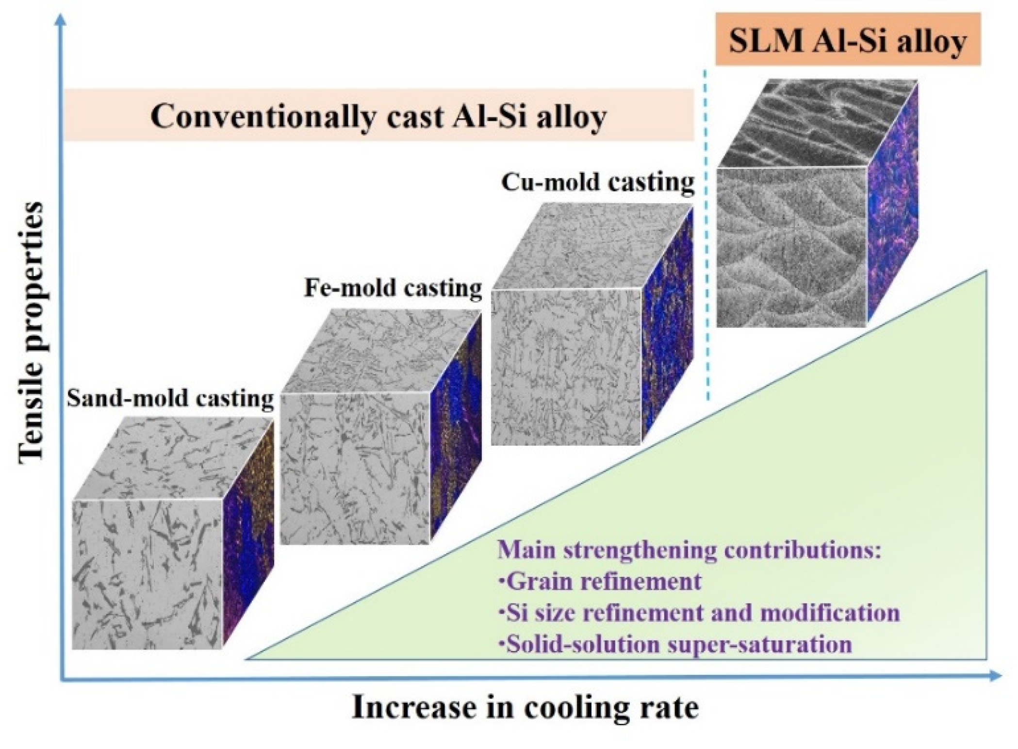
4.2. Strengthening Mechanism

The differences in mechanical properties among the four alloys are related to the differences in their microstructures. Normally, the coarse microstructure, such as large grain size and large Si particle, leads to a worse property.
Firstly, the semi-empirical Hall-Petch relationship as indicated by Equation (4) can explain the effect of grain size on the yield strength [48]:
σ s = σ 0 + k d 1 / 2
where σs is the proof stress, σ0 is the friction stress for dislocation movement, k is the Hall-Petch coefficient, and d is the average grain size. When the grain size is well refined, the pile-up of dislocations at grain boundaries happens, which increases the resistance of dislocations to slip and then increases the yield strength. The uniform microstructure distributes stress more uniformly and improves the plasticity. Therefore, the SLM Al-10Si-0.5Mg alloy shows the best yield strength as a result of the finest grain size.
Secondly, the Si particle size has great influence on the mechanical property. When strengthening particles are dispersed evenly, the dislocation motion can be inhibited and the slip can be dispersed, thus the localized shear stress can be relieved and the yield strength can be increased [11,49,50,51,52]. Therefore, the continuous network distribution of eutectic Si is another important factor that improves the strength of SLM Al-10Si-0.5Mg alloy. In contrast, the coarse α-Al grain size and baculiform or acicular eutectic Si particles in sand-casting Al-10Si-0.5Mg alloy significantly deteriorates the mechanical properties, similar to previous study [53,54]. Additionally, the platelet-like Fe-rich particle always forms during sand-cast condition. This type of Fe-rich particle is brittle and undesirable for toughness because it can induce stress concentration and act as a crack source [37]. Thus, the sand-cast Al-10Si-0.5Mg alloy shows the lowest yield strength (125 ± 5 MPa) and elongation (0.8 ± 0.2%).
Thirdly, the solid-solution strengthening factor should also be considered. In the binary Al-Si system [22], the maximum solubility of Si in α-Al is 1.65 wt.% at the eutectic temperature of 577 °C. The solubility drops rapidly to 0.06 wt.% at 300 °C and further to a negligible value at 25 °C. During the SLM process of Al-Si alloy, the ultra-rapid melting and solidification effect leads to non-equilibrium solidification behavior, which alters the phase diagram and improves the super-saturation of Si in Al matrix [41,49]. For example, Delahaye et al. showed that the Si amount in solid-solution Al cells of SLM Al-10Si-0.5Mg alloy reached ~4 wt.% [34], while Wei et al. even found this value high as ~8 wt.% [55]. In this study, the super-saturation was measured as ~9.3 wt.%. Thus, the solid-solution strengthening effect in SLM Al-10Si-0.5Mg alloy is higher than in conventionally cast counterparts. This super-saturation effect may cause a greater brittleness in the matrix and a worse elongation. However, as seen from Figure 10, the elongation of SLM Al-10Si-Mg alloy is much higher than the conventional three castings (i.e., 4% vs. 0.8–1.5%). This is because, in addition to the super-saturation of matrix, the Si phase morphology can greatly influence the ductility, as stated in the above paragraph. The blocky Si phase that always presents in conventional casting can cause stress concentration and sharply decrease the ductility.
Based on the above analysis, the relationships among preparation method, microstructure and mechanical properties can be drawn as the schematic illustration in Figure 12. However, because all the factors change simultaneously, i.e., grain size, Si size and super-saturation, the quantitative work to disclose the contribution of each strengthening factor will need to be determined in a future study. Moreover, in order to supply useful guidance for engineering applications, Table 2 summarizes the comparisons of mechanical properties of as-built SLM Al-10Si-0.5Mg alloys among some reported studies (without heat treatment) [12,56,57,58,59,60,61,62,63,64]. The deviations in mechanical properties among different reports are very normal, which are related to respective fabrication conditions that produce distinctive microstructure features and defect distributions.
If the SLM sample is further subjected to suitable heat treatments, the combination between strength and elongation can be well adjusted through modifying the distribution of Si eutectic phase, Si super-saturation and Mg2Si precipitates. For example, Li et al. reported that when SLM Al-10Si-Mg alloy was subjected to T4 heat treatment (450 °C × 2 h), the YS decreased dramatically from 270 MPa to 196 MPa, while the elongation increased significantly from 4% to 13.4% [47]. Fousová et al. reported that when SLM Al-10Si-Mg alloy was subjected to T6 heat treatment (510 °C × 6 h + 170 °C × 4 h), the YS decreased from 255 MPa to 210 MPa, while the elongation increased from 2.2% to 4.9% [41]. However, the systematic work of heat treatments for our alloys still requires further investigation.
Ψ = P ν h t

5. Conclusions

The microstructures and mechanical properties of four hypoeutectic Al-10Si-0.5Mg alloys prepared under various cooling rates () via sand-mold (3.5 °C/s), Fe-mold (12.5 °C/s), Cu-mold (80 °C/s) and selective laser melting (SLM, perhaps 106~108 °C/s) were systematically compared. The results show that significantly influences the grain morphology, grain size and eutectic Si particle distributions, which finally influences the mechanical properties. With increasing from 3.5 to 80 and finally to 106–108 °C/s, the grain morphology and size are continuously refined from coarse dendrites (~3522 ± 668 μm) to fine dendrites (~365 ± 36 μm), but finally to a mixed grain structure composed of columnar and fine grains (~10 μm of fine grains). The shape of eutectic Si particles transforms from blocky in sand/Fe-mold casting to needle-like in Cu-mold casting and finally to a fine fibrous network in SLM alloy. With increasing cooling condition from sand-mold casting to SLM, the tensile yield strength and elongation is improved from 125 ± 5 MPa to 262 ± 3 MPa, from 0.8 ± 0.2% to 4.0 ± 0.2% (SLM condition), respectively. The main strengthening factors were discussed, which are mainly ascribed to the refinement of grain size, refinement of Si particles and an increase in super-saturation of Al matrix (especially under SLM conditions).

Author Contributions

Conceptualization, M.S.; methodology, M.S.; software, M.G.; validation, M.G. and J.H.; formal analysis, M.G. and M.S.; investigation, M.G. and M.S.; resources, S.P.; data curation, J.H.; writing—original draft preparation, M.S.; writing—review and editing, M.G. and S.P.; visualization, J.H.; supervision, M.S.; project administration, M.S.; funding acquisition, M.S. All authors have read and agreed to the published version of the manuscript.

Funding

This work is supported by National Natural Science Foundation of China (Grant No. 51701124).

Data Availability Statement

The data presented in this study are available on request from the corresponding author.

Acknowledgments

Ghulam Asghar with Shanghai Jiao Tong University (SJTU, China) is thanked for kind help with discussion of the manuscript.

Conflicts of Interest

The authors declare no conflict of interest.

References

  1. Ding, X.; Wang, L. Heat transfer and fluid flow of molten pool during selective laser melting of AlSi10Mg powder: Simulation and experiment. J. Manuf. Process. 2017, 26, 280–289. [Google Scholar] [CrossRef]
  2. Yang, C.; Zhu, K.; Liu, Y.; Cai, Y.; Liu, W.; Zhang, K.; Huang, J. A comparative study of fatigue energy dissipation of additive manufactured and cast AlSi10Mg alloy. Metals 2021, 11, 1274. [Google Scholar] [CrossRef]
  3. Gandolfi, M.; Xavier, M.G.C.; Gomes, L.F.; Reyes, R.A.V.; Garcia, A.; Spinelli, J.E. Relationship between microstructure evolution and tensile properties of AlSi10Mg alloys with varying mg content and solidification cooling rates. Metals 2021, 11, 1019. [Google Scholar] [CrossRef]
  4. Tawfik, N.L. Mechanical properties of rapidly solidified ribbons of some Al-Si based alloys. J. Mater. Sci. 1997, 32, 2997–3000. [Google Scholar] [CrossRef]
  5. Kimura, T.; Nakamoto, T. Microstructures and mechanical properties of A356 (AlSi7Mg0.3) aluminum alloy fabricated by selective laser melting. Mater. Des. 2016, 89, 1294–1301. [Google Scholar] [CrossRef]
  6. Li, Z.; Kuai, Z.; Bai, P.; Nie, Y.; Fu, G.; Liu, W.; Yang, S. Microstructure and tensile properties of AlSi10Mg alloy manufactured by multi-laser beam selective laser melting (SLM). Metals 2019, 9, 1337. [Google Scholar] [CrossRef] [Green Version]
  7. Marola, S.; Manfredi, D.; Fiore, G.; Poletti, M.G.; Lombardi, M.; Fino, P.; Battezzati, L. A comparison of selective laser melting with bulk rapid solidification of AlSi10Mg alloy. J. Alloys Compd. 2018, 742, 271–279. [Google Scholar] [CrossRef]
  8. Fathi, P.; Mohammadi, M.; Duan, X.; Nasiri, A.M. A comparative study on corrosion and microstructure of direct metal laser sintered AlSi10Mg_200C and die cast A360.1 aluminum. J. Mater. Process. Technol. 2018, 259, 1–14. [Google Scholar] [CrossRef]
  9. Langelandsvik, G.; Horgar, A.; Furu, T.; Roven, H.J.; Akselsen, O.M. Comparative study of eutectic Al-Si alloys manufactured by WAAM and casting. Int. J. Adv. Manuf. Technol. 2020, 110, 935–947. [Google Scholar] [CrossRef]
  10. Yan, Q.; Song, B.; Shi, Y. Comparative study of performance comparison of AlSi10Mg alloy prepared by selective laser melting and casting. J. Mater. Sci. Technol. 2020, 41, 199–208. [Google Scholar] [CrossRef]
  11. Girelli, L.; Tocci, M.; Gelfi, M.; Pola, A. Study of heat treatment parameters for additively manufactured AlSi10Mg in comparison with corresponding cast alloy. Mater. Sci. Eng. A 2019, 739, 317–328. [Google Scholar] [CrossRef]
  12. Zyguła, K.; Nosek, B.; Pasiowiec, H.; Szysiak, N. Mechanical properties and microstructure of AlSi10Mg alloy obtained by casting and SLM technique. World Sci. News 2018, 104, 456–466. [Google Scholar]
  13. Ridgeway, C.D.; Cheng, G.; Luo, A.A. Predicting primary dendrite arm spacing in Al-Si-Mg alloys: Effect of Mg alloying. J. Mater. Sci. 2019, 54, 9907–9920. [Google Scholar] [CrossRef]
  14. Easton, M.; StJohn, D. Grain refinement of aluminum alloys: Part I. the nucleant and solute paradigms—A review of the literature. Metall. Mater. Trans. A 1999, 30, 1613–1623. [Google Scholar] [CrossRef]
  15. Ludwig, T.H.; Dæhlen, E.S.; Schaffer, P.L.; Arnberg, L. The effect of Ca and P interaction on the Al-Si eutectic in a hypoeutectic Al-Si alloy. J. Alloys Compd. 2014, 586, 180–190. [Google Scholar] [CrossRef]
  16. Flood, S.C.; Hunt, J.D. Modification of Al-Si eutectic alloys with Na. Met. Sci. 1981, 15, 287–294. [Google Scholar] [CrossRef]
  17. Dahle, A.K.; Nogita, K.; McDonald, S.D.; Dinnis, C.; Lu, L. Eutectic modification and microstructure development in Al-Si Alloys. Mat. Sci. Eng. A 2005, 413, 243–248. [Google Scholar] [CrossRef]
  18. Hegde, S.; Prabhu, K.N. Modification of eutectic silicon in Al-Si alloys. J. Mater. Sci. 2008, 43, 3009–3027. [Google Scholar] [CrossRef]
  19. Kotadia, H.R.; Babu, N.H.; Zhang, H.; Fan, Z. Microstructural refinement of Al-10.2%Si alloy by intensive shearing. Mater. Lett. 2010, 64, 671–673. [Google Scholar] [CrossRef]
  20. Sun, M.; Stjohn, D.H.; Easton, M.A.; Wang, K.; Ni, J. Effect of cooling rate on the grain refinement of Mg-Y-Zr alloys. Metall. Mater. Trans. A 2020, 51, 482–496. [Google Scholar] [CrossRef]
  21. Li, Y.; Gu, D. Parametric analysis of thermal behavior during selective laser melting additive manufacturing of aluminum alloy powder. Mater. Des. 2014, 63, 856–867. [Google Scholar] [CrossRef]
  22. Zhang, J.; Song, B.; Wei, Q.; Bourell, D.; Shi, Y. A review of selective laser melting of aluminum alloys: Processing, microstructure, property and developing trends. J. Mater. Sci. Technol. 2019, 35, 270–284. [Google Scholar] [CrossRef]
  23. Sun, M.; Hu, X.; Peng, L.; Fu, P.; Peng, Y. Effects of Sm on the grain refinement, microstructures and mechanical properties of AZ31 magnesium alloy. Mat. Sci. Eng. A 2014, 620, 89–96. [Google Scholar] [CrossRef]
  24. Zaretsky, E.; Stern, A.; Frage, N. Dynamic response of AlSi10Mg alloy fabricated by selective laser melting. Mat. Sci. Eng. A 2017, 688, 364–370. [Google Scholar] [CrossRef]
  25. Li, J.H.; Zarif, M.Z.; Albu, M.; McKay, B.J.; Hofer, F.; Schumacher, P. Nucleation kinetics of entrained eutectic Si in Al-5Si alloys. Acta. Mater. 2014, 72, 80–98. [Google Scholar] [CrossRef]
  26. Wang, Q.G.; Davidson, C.J. Solidification and precipitation behaviour of Al-Si-Mg casting alloys. J. Mater. Sci. 2001, 36, 739–750. [Google Scholar] [CrossRef]
  27. Liao, H.; Sun, Y.; Sun, G. Restraining effect of strontium on the crystallization of Mg2Si phase during solidification in Al-Si-Mg casting alloys and mechanisms. Mat. Sci. Eng. A 2003, 358, 164–170. [Google Scholar]
  28. Chen, B.; Moon, S.K.; Yao, X.; Bi, G.; Shen, J.; Umeda, J.; Kondoh, K. Strength and strain hardening of a selective laser melted AlSi10Mg alloy. Scr. Mater. 2017, 141, 45–49. [Google Scholar] [CrossRef]
  29. Thijs, L.; Kempen, K.; Kruth, J.P.; Humbeeck, J.V. Fine-structured aluminium products with controllable texture by selective laser melting of pre-alloyed AlSi10Mg powder. Acta. Mater. 2013, 61, 1809–1819. [Google Scholar] [CrossRef] [Green Version]
  30. Wei, W.; Zhou, Y.; Liu, W.; Li, N.; Yan, J.; Li, H. Microstructural characterization, mechanical properties, and corrosion resistance of dental Co-Cr-Mo-W alloys manufactured by selective laser melting. J. Mater. Eng. Perform. 2018, 27, 5312–5320. [Google Scholar] [CrossRef]
  31. Lu, Y.; Yang, C.; Liu, Y.; Yang, K.; Lin, J. Characterization of lattice defects and tensile deformation of biomedical Co29Cr9W3Cu alloy produced by selective laser melting. Addit. Manuf. 2019, 30, 100908. [Google Scholar] [CrossRef]
  32. Lu, L.; Dahle, A.K. Iron-rich intermetallic phases and their role in casting defect formation in hypoeutectic Al-Si alloys. Metall. Mater. Trans. A 2005, 36, 819–835. [Google Scholar]
  33. Revillaz, R.I.; De Graeve, I. Influence of Si content on the microstructure and corrosion behavior of additive manufactured Al-Si alloys. J. Electrochem. Soc. 2018, 165, C926–C932. [Google Scholar] [CrossRef]
  34. Delahaye, J.; Tchuindjang, J.T.; Beckers, J.L.; Rigo, O.; Habraken, A.M.; Mertens, A. Influence of Si precipitates on fracture mechanisms of AlSi10Mg parts processed by selective laser melting. Acta. Mater. 2019, 175, 160–170. [Google Scholar] [CrossRef]
  35. Tan, Q.; Zhang, J.; Mo, N.; Fan, Z.; Yin, Y.; Bermingham, M.; Liu, Y.; Huang, H.; Zhang, M. A novel method to 3D-print fine-grained AlSi10Mg alloy with isotropic properties via inoculation with LaB6 nanoparticles. Addit. Manuf. 2020, 32, 101034. [Google Scholar] [CrossRef]
  36. Choi, S.W.; Kim, Y.M.; Lee, K.M.; Cho, H.S.; Hong, S.K.; Kim, Y.C.; Kang, C.S.; Kumai, S. The effects of cooling rate and heat treatment on mechanical and thermal characteristics of Al-Si-Cu-Mg foundry alloys. J. Alloys Compd. 2014, 617, 654–659. [Google Scholar] [CrossRef]
  37. Ran, G.; Zhou, J.E.; Wang, Q.G. Precipitates and tensile fracture mechanism in a sand cast A356 aluminum alloy. J. Mater. Process. Technol. 2008, 207, 46–52. [Google Scholar] [CrossRef]
  38. Tradowsky, U.; White, J.; Ward, R.M.; Read, N.; Reimers, W.; Attallah, M.M. Selective laser melting of AlSi10Mg: Influence of post-processing on the microstructural and tensile properties development. Mater. Des. 2016, 105, 212–222. [Google Scholar] [CrossRef] [Green Version]
  39. Kurz, W.; Fisher, D.J. Fundamentals of Solidification, 4th ed.; Trans Tech Publications: Hampshire, UK, 1998; pp. 65–89. [Google Scholar]
  40. Prashanth, K.G.; Scudino, S.; Klauss, H.J.; Surreddi, K.B.; Löber, L.; Wang, Z.; Chaubey, A.K.; Kühn, U.; Eckert, J. Microstructure and mechanical properties of Al-12Si produced by selective laser melting: Effect of heat treatment. Mater. Sci. Eng. A 2014, 590, 153–160. [Google Scholar] [CrossRef]
  41. Fousová, M.; Dvorský, D.; Michalcová, A.; Vojtěch, D. Changes in the microstructure and mechanical properties of additively manufactured AlSi10Mg alloy after exposure to elevated temperatures. Mater. Charact. 2018, 137, 119–126. [Google Scholar] [CrossRef]
  42. Easton, M.; Davidson, C.; St. John, D. Effect of alloy composition on the dendrite arm spacing of multicomponent aluminum alloys. Metall. Mater. Trans. A 2010, 41, 1528–1538. [Google Scholar] [CrossRef]
  43. Nadella, R.; Eskin, D.G.; Du, Q.; Katgerman, L. Macrosegregation in direct-chill casting of aluminium alloys. Prog. Mater. Sci. 2008, 53, 421–480. [Google Scholar] [CrossRef] [Green Version]
  44. St. John, D.H.; Ma, Q.; Easton, M.A.; Cao, P. The Interdependence Theory: The relationship between grain formation and nucleant selection. Acta. Mater. 2011, 59, 4907–4921. [Google Scholar] [CrossRef]
  45. St. John, D.H.; Easton, M.A.; Ma, Q.; Taylor, J.A. Grain refinement of magnesium alloys: A review of recent research, theoretical developments, and their application. Metall. Mater. Trans. A 2013, 44, 2935–2949. [Google Scholar] [CrossRef] [Green Version]
  46. Easton, M.A.; St. John, D.H. Improved prediction of the grain size of aluminum alloys that includes the effect of cooling rate. Mater. Sci. Eng. A 2008, 486, 8–13. [Google Scholar] [CrossRef]
  47. Li, X.P.; Wang, X.J.; Saunders, M.; Suvorova, A.; Zhang, L.C.; Liu, Y.J.; Fang, M.H.; Huang, Z.H.; Sercombe, T.B. A selective laser melting and solution heat treatment refined Al-12Si alloy with a controllable ultrafine eutectic microstructure and 25% tensile ductility. Acta. Mater. 2015, 95, 74–82. [Google Scholar] [CrossRef]
  48. Mukhopadhyay, N.K.; Paufler, P. Micro and nanoindentation techniques for mechanical characterisation of materials. Int. Mater. Rev. 2006, 51, 209–245. [Google Scholar] [CrossRef]
  49. Ye, H. An overview of the development of Al-Si-Alloy based material for engine applications. J. Mater. Eng. Perform. 2003, 12, 288–297. [Google Scholar] [CrossRef]
  50. Prashanth, K.G.; Scudino, S.; Eckert, J. Tensile properties of Al-12Si fabricated via selective laser melting (SLM) at different temperatures. Technologies 2016, 4, 38. [Google Scholar] [CrossRef] [Green Version]
  51. Wu, J.; Wang, X.Q.; Wang, W.; Attallah, M.M.; Loretto, M.H. Microstructure and strength of selectively laser melted AlSi10Mg. Acta Mater. 2016, 117, 311–320. [Google Scholar] [CrossRef] [Green Version]
  52. Li, L.; Li, D.; Feng, J.; Zhang, Y.; Kang, Y. Effect of cooling rates on the microstructure and mechanical property of la modified Al7SiMg alloys processed by gravity die casting and semi-solid die casting. Metals 2020, 10, 549. [Google Scholar] [CrossRef]
  53. Martin, R.; Ehsan, G.; Toni, B.; Salem, S. Interactive effects of grain refinement, eutectic modification and solidification rate on tensile properties of Al-10Si alloy. Mater. Sci. Eng. A 2017, 703, 270–279. [Google Scholar]
  54. Jiang, B.; Ji, Z.; Hu, M.; Xu, H.; Xu, S. A novel modifier on eutectic Si and mechanical properties of Al-Si alloy. Mater. Lett. 2019, 239, 13–16. [Google Scholar] [CrossRef]
  55. Wei, P.; Wei, Z.; Chen, Z.; Du, J.; He, Y.; Li, J.; Zhou, Y. The AlSi10Mg samples produced by selective laser melting: Single track, densification, microstructure and mechanical behavior. Appl. Surf. Sci. 2017, 408, 38–50. [Google Scholar] [CrossRef]
  56. Jawade, S.A.; Joshi, R.S.; Desai, S.B. Comparative study of mechanical properties of additively manufactured aluminum alloy. Mater. Today Proc. 2021, 46, 9270–9274. [Google Scholar] [CrossRef]
  57. Li, Q.; Qiu, F.; Dong, B.; Yang, H.; Shu, S.; Zha, M.; Jiang, Q. Investigation of the influences of ternary Mg addition on the solidification microstructure and mechanical properties of as-cast Al-10Si alloys. Mater. Sci. Eng. A 2020, 798, 140247. [Google Scholar] [CrossRef]
  58. Lumley, R. Technical Data Sheets for Heat Treated Aluminium High Pressure Die Castings; CSIRO: Canberra, Australia, 2008. [Google Scholar]
  59. Zhang, C.; Zhu, H.; Hu, Z.; Zhang, L.; Zeng, X. A comparative study on single-laser and multi-laser selective laser melting AlSi10Mg: Defects, microstructure and mechanical properties. Mater. Sci. Eng. A 2019, 746, 416–423. [Google Scholar] [CrossRef]
  60. Aboulkhair, N.T.; Maskery, I.; Tuck, C.; Ashcroft, I.; Everitt, N.M. The microstructure and mechanical properties of selectively laser melted AlSi10Mg: The effect of a conventional T6-like heat treatment. Mater. Sci. Eng. A 2016, 667, 139–146. [Google Scholar] [CrossRef]
  61. Li, W.; Li, S.; Liu, J.; Zhang, A.; Zhou, Y.; Wei, Q.; Yan, C.; Shi, Y. Effect of heat treatment on AlSi10Mg alloy fabricated by selective laser melting: Microstructure evolution, mechanical properties and fracture mechanism. Mat. Sci. Eng. A 2016, 663, 116–125. [Google Scholar] [CrossRef]
  62. Read, N.; Wang, W.; Essa, K.; Attallah, M.M. Selective laser melting of AlSi10Mg alloy: Process optimization and mechanical properties development. Mater. Des. 2015, 65, 417–424. [Google Scholar] [CrossRef] [Green Version]
  63. Qian, G.; Jian, Z.; Qian, Y.; Pan, X.; Ma, X.; Hong, Y. Very-high-cycle fatigue behavior of AlSi10Mg manufactured by selective laser melting: Effect of build orientation and mean stress. Int. J. Fatigue 2020, 138, 105696. [Google Scholar] [CrossRef]
  64. Xiong, Z.H.; Liu, S.L.; Li, S.F.; Shi, Y.; Yang, Y.F.; Misra, R.D.K. Role of melt pool boundary condition in determining the mechanical properties of selective laser melting AlSi10Mg alloy. Mater. Sci. Eng. A 2019, 740, 148–156. [Google Scholar] [CrossRef]
Figure 1. Alloy preparation details. (a) Conventional casting process using crucible electrical furnace and the alloy melt was poured into sand, Fe or Cu mold with the same dimensions (in mm); (b) SEM and particle distribution of Al10SiMg raw powder used for selective laser melting (SLM) and the photo of as-built samples.
Metals 12 00142 g001
Figure 2. Cooling curves of sand/Fe/Cu-mold cast Al-10Si-0.5Mg alloys. The cooling curve of Cu-mold was difficult to capture because of fast cooling effect.
Metals 12 00142 g002
Figure 3. Dimensions of tensile testing sample (in mm, reproduced or adapted from [23], with permission from Elsevier, 2014).
Metals 12 00142 g003
Figure 4. XRD patterns of Al-10Si-0.5Mg alloys fabricated under different conditions.
Metals 12 00142 g004
Figure 5. Optical microstructure of Al-10Si-0.5Mg alloys prepared with: (a) sand-mold, (b) Fe-mold, (c) Cu-mold and (d,e) SLM. The image at upper-right corner of (ac) is the enlarged view; (f) 3D microstructure of SLM alloy constructed with OM images. The color images were observed under the polarized light mode of a microscope to display the grain morphology. Note that the magnification of (d) is different from that of (ac) to display tiny melt pools (MPs).
Metals 12 00142 g005
Figure 6. Average grain size of Al-10Si-0.5Mg alloys prepared under different conditions. No SDAS data for SLM alloy due to inapparent dendrites.
Metals 12 00142 g006
Figure 7. SEM microstructures of Al-10Si-0.5Mg alloys prepared with: (a,a’) sand-mold, (b,b’) Fe-mold, and (c,c’) Cu-mold. (a’) shows the Fe-rich phase in sand-cast alloy; (b’) and (c’) show the enlarged view of selected area in (b) and (c), respectively.
Metals 12 00142 g007
Figure 8. SEM microstructures of SLM Al-10Si-0.5Mg alloy: (a,a’) along the transverse direction (XOY) where (a’) is the enlarged view of selected area in (a); (b,b’) along longitudinal direction (XOZ) where (b’) is the enlarged view of selected area in (b); (c) EBSD grain structure along longitudinal direction; (d) 3D microstructure constructed with 10,000 × SEM images.
Metals 12 00142 g008
Figure 9. Area percentage (S, %) of Si particles within each main length (Lm) range in the sand/Fe/Cu-mold cast Al-10Si-0.5Mg alloys. Excluding SLM alloy due to the continuous network distribution of Si phase that is difficult to count for each size range.
Metals 12 00142 g009
Figure 10. Tensile properties of Al-10Si-0.5Mg alloys prepared under different conditions.
Metals 12 00142 g010
Figure 11. Tensile fractographies of Al-10Si-0.5Mg alloys prepared under different conditions. Left column (ad) low magnification, right column (a’d’) higher magnification of the area marked by boxes and arrows. Note that the magnification of (d’) is higher as 40,000× to show fine microstructure.
Metals 12 00142 g011
Figure 12. Schematic illustration showing the relationships among preparation method, microstructure and mechanical properties.
Metals 12 00142 g012
Table 1. Compositions (wt.%) of Al-10Si-0.5Mg alloys analyzed with ICP-AES.
Preparation ConditionSiMgFeAlNote
Sand-mold9.490.420.21Bal.cast from the same batch of melt
Fe-mold
Cu-mold
SLM9.250.260.14Bal.--
Table 2. Tensile mechanical properties of conventionally cast and as-built SLM Al-10Si-Mg alloys summarized from some references (without heat treatment).
Conventionally Cast Al-10Si-Mg Alloy *1YS (MPa)UTS (MPa)EL. (%)Ref.
SCParameters not specified2052552.8[56]
Melting, pouring at 700 °C in a sand mold preheated to 200 °C125 ± 5137 ± 60.8 ± 0.2This study
GCMelting, pouring at 700 °C in a steel mold preheated to 200 °C180 ± 6228 ± 31.7 ± 0.3This study
Preparation parameters not specified1251561.0[56]
Melting, pouring at 750 °C in a steel mold preheated to 373 °C931998.1[57]
Industrial casting but parameters not specified112 ± 10210 ± 83.9 ± 1.0[11]
HPDCPreparation parameters not specified160~185300~3503~5[58] *2
Industrial casting but parameters not specified991936.5[12]
SLM Al-10Si-Mg alloy built with conditions *3Tensile testing direction:
H—horizontal direction,
V—vertical direction.
D
(µm)
P
(W)
ν
(mm/s)
h
(µm)
t
(µm)
Ψ
(J/mm3)
10027510008030115V262 ± 3382 ± 54.0 ± 0.2This study
10049018001004068H314 ± 6481 ± 23.3 ± 0.2[59]
20057013025108268 ± 2333 ± 151.4 ± 0.3[60] *4
8035011401705036H322 ± 8434 ± 115.3 ± 0.2[61]
200250500 50 H3014024.3[56]
V2693374.1
10037013001903050H264 ± 4452 ± 18.6 ± 1.0[11]
V247 ± 1482 ± 16.5 ± 0.3
175102597.53058H2503401.5[62] *5
V2403301.0
503701300190 H27046512.7[63]
V2354404.3
35092040H2203607.1[64]
V1903634.3
*1 SC—sand casting, GC—gravity casting, HPDC—high pressure die-casting. *2 Because there is no data of HPDC Al-10Si-0.5Mg alloy available, commercial A360 alloy with similar compositions of Al-(9–10)Si-(<1.3)Fe-(<0.6)Cu-(0.4~0.6)Mg-(<0.35)Mn in reference [58] is selected as a comparative example. *3 Meaning of parameters, D—beam diameter, P—laser power, ν—scan speed, h—hatching distance, t—layer thickness, Ψ—energy density. Except references [59,64], the values of Ψ were calculated by the present authors with Equation (5) [5,62]. *4 The direction of tensile sample was not specified in reference [60]. *5 The values were approximately read from the plots in reference [62] since they were not described specifically.
Publisher’s Note: MDPI stays neutral with regard to jurisdictional claims in published maps and institutional affiliations.

