
Low Cycle Fatigue Performance of Additively Processed and Heat-Treated Ti-6Al-7Nb Alloy for Biomedical Applications

 , , ,
, , ,  , ,
, ,
Abstract
1. Introduction
2. Materials and Methods
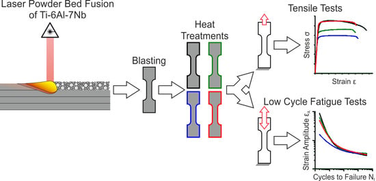
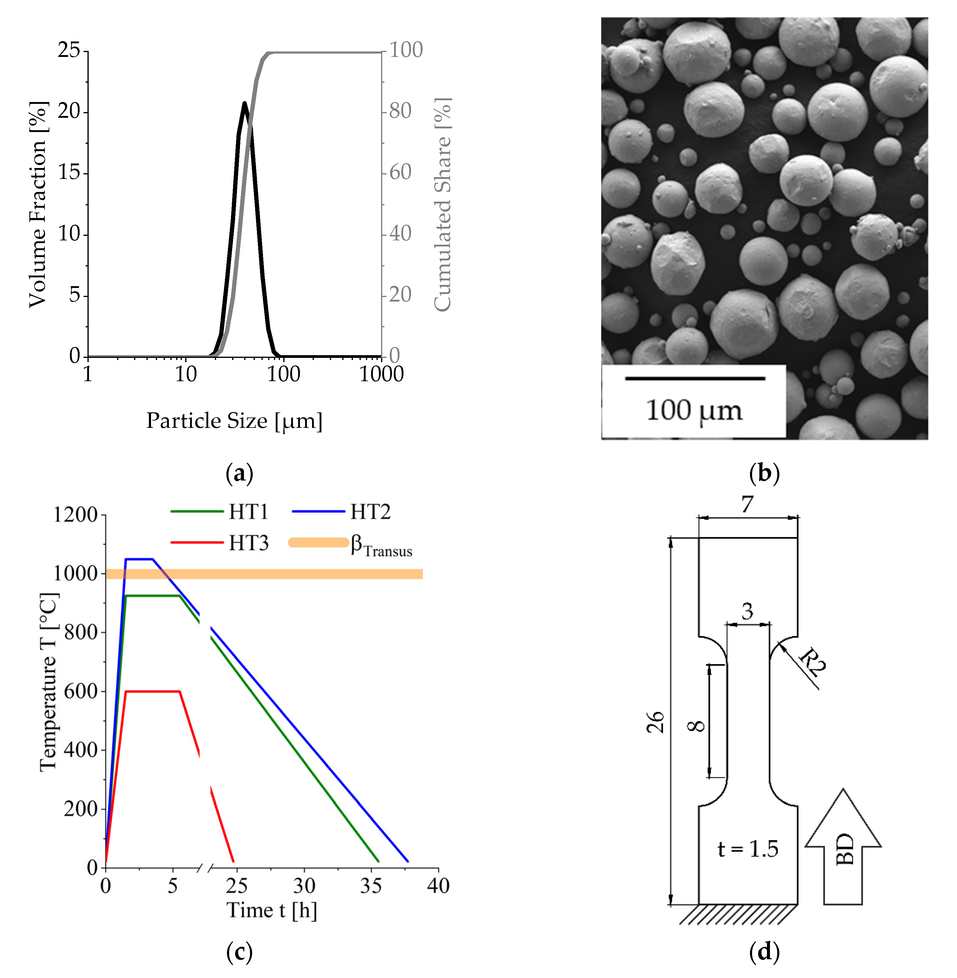
2.1. Manufacturing Procedure, Materials, and Mechanical Characterization
2.2. Biocompatibility Investigations
2.2.1. Cytocompatibility Testing
2.2.2. Antibacterial Examinations
3. Results and Discussion
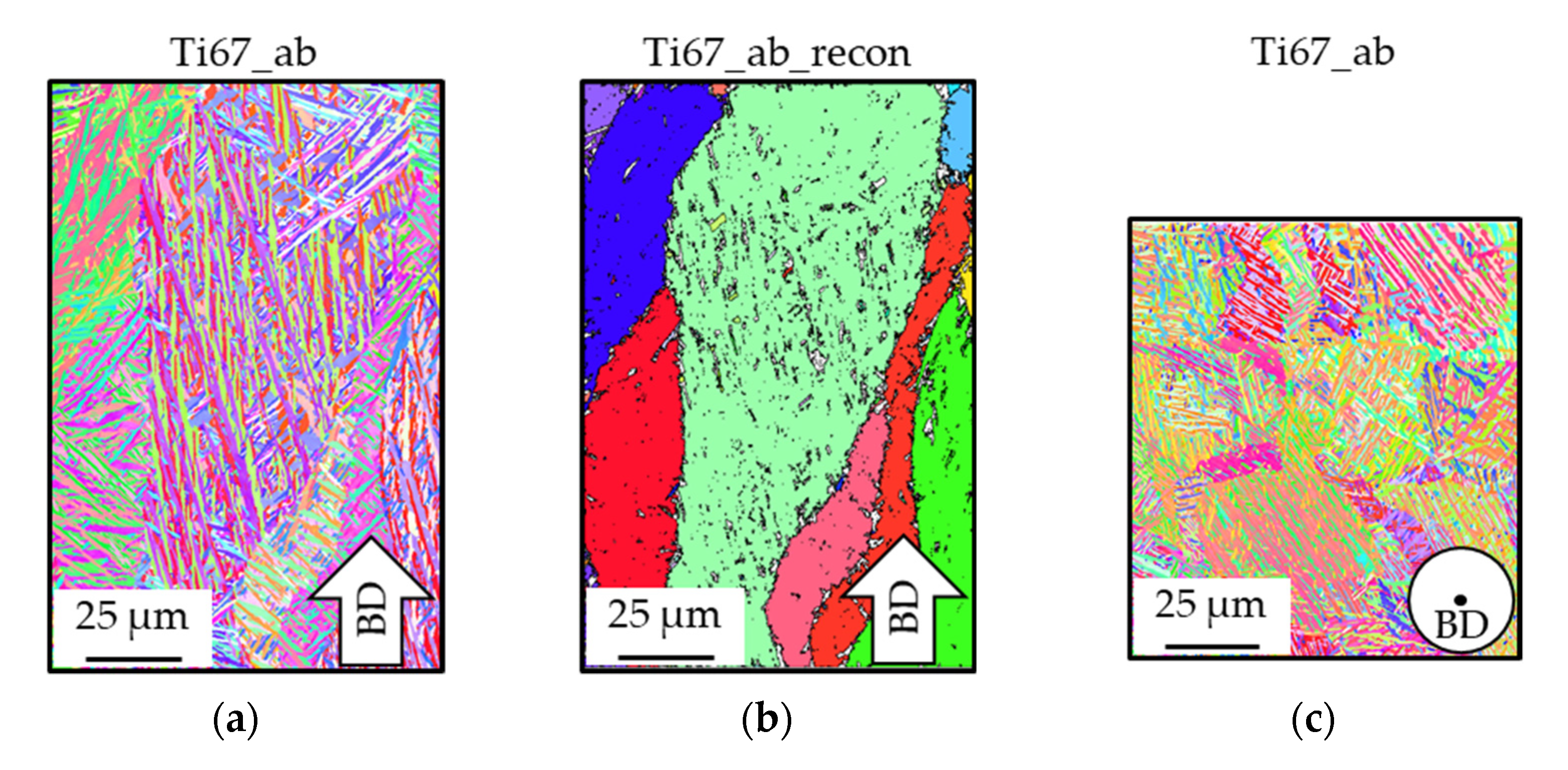
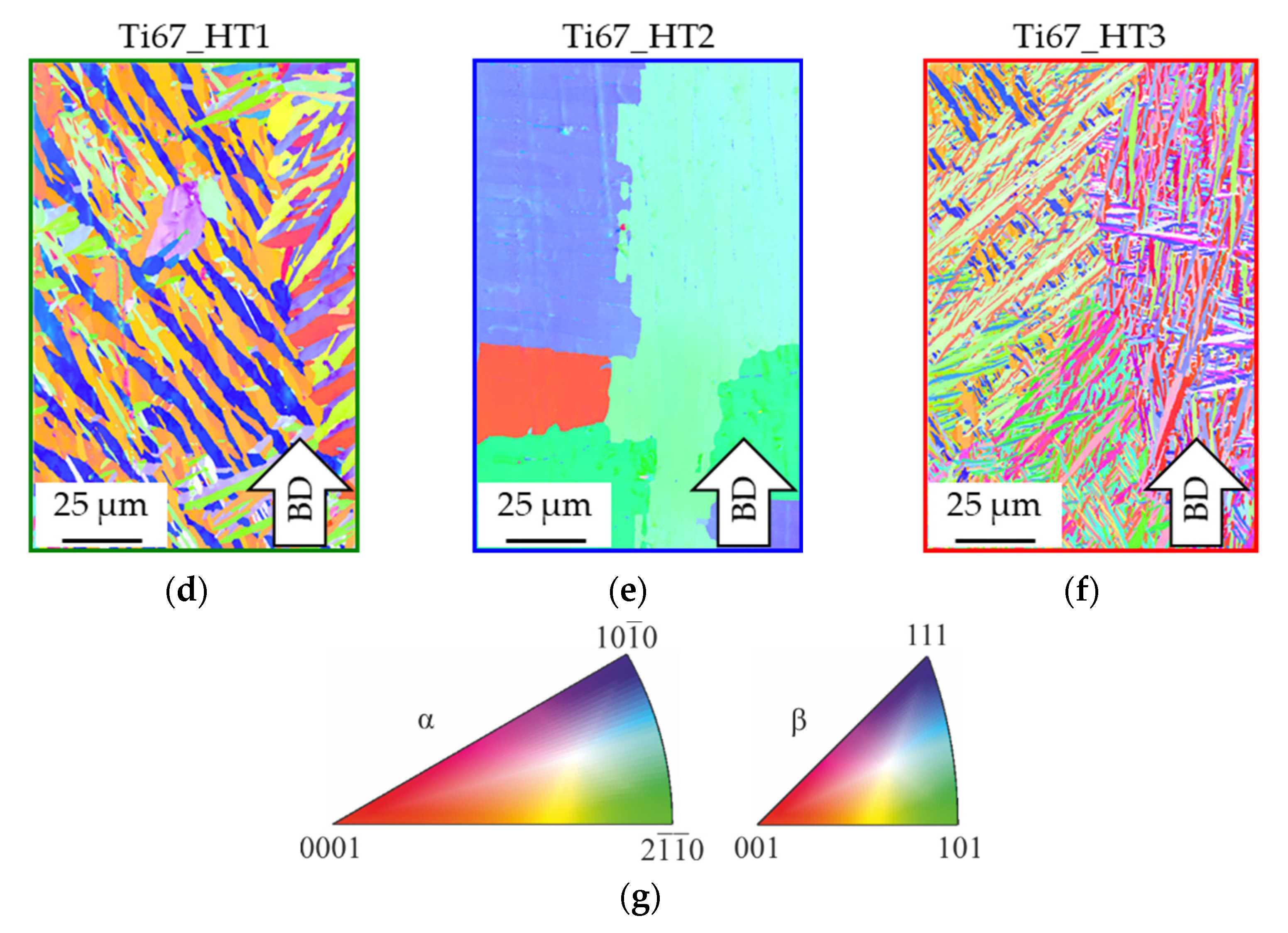
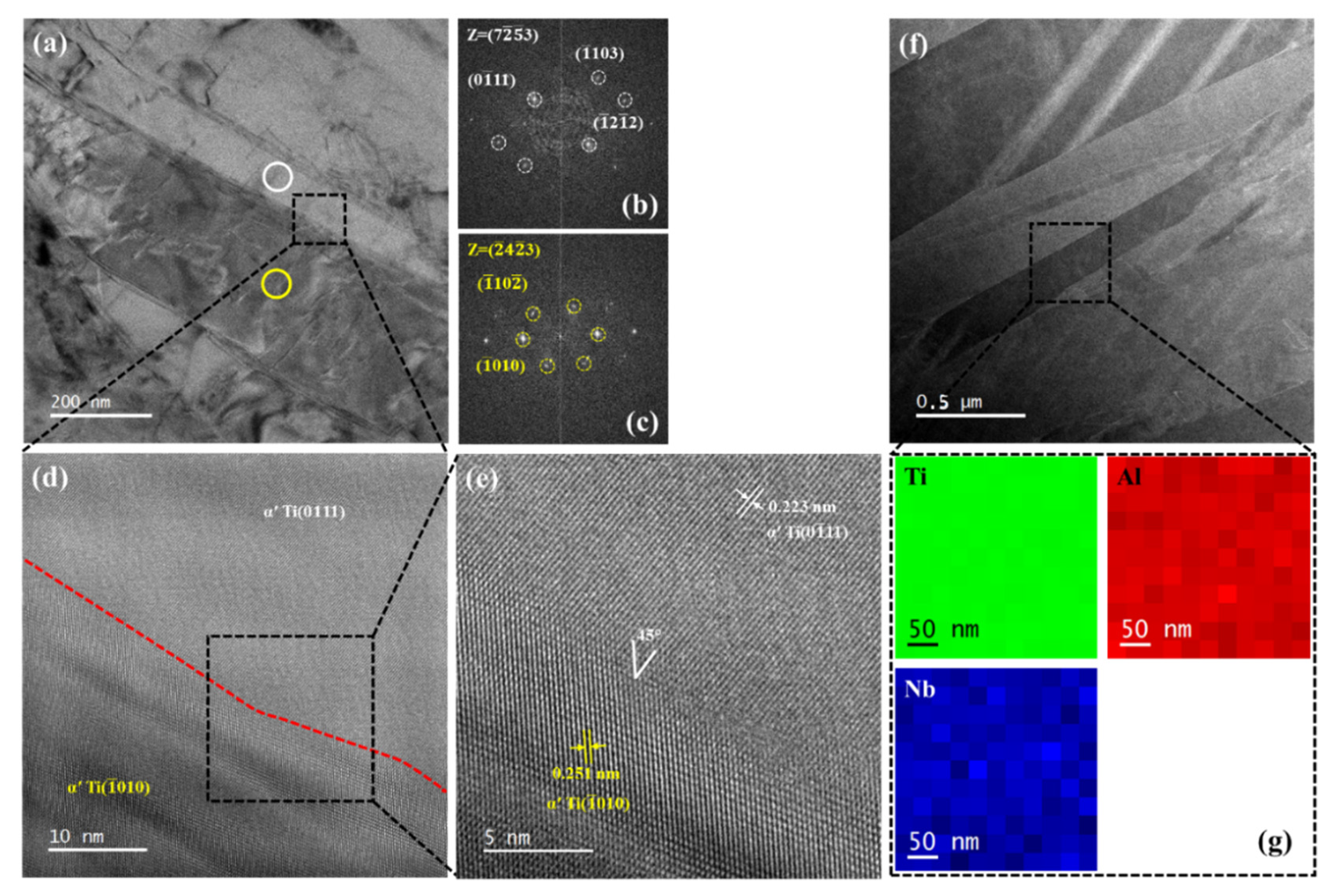
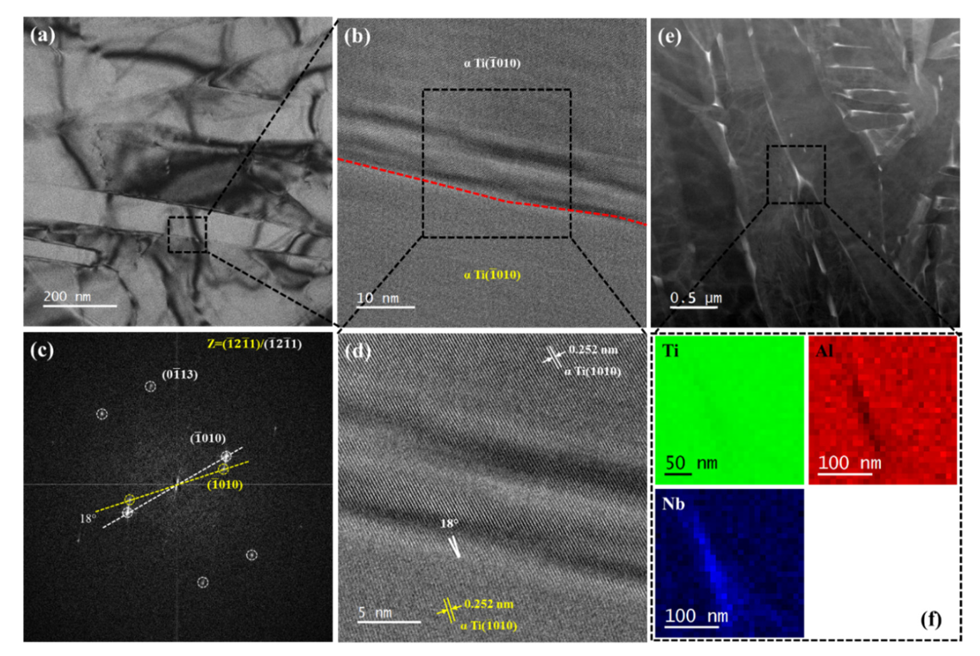
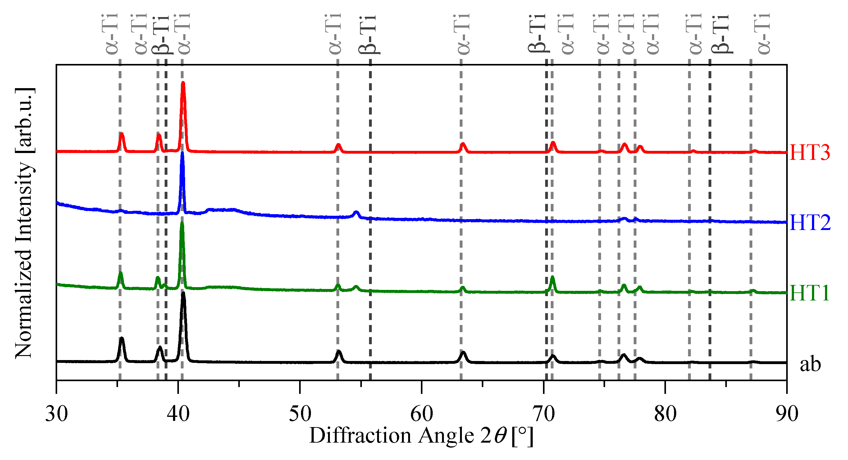
3.1. Microstructure and Nanostructure of as-Built and Heat-Treated Ti-6Al-7Nb

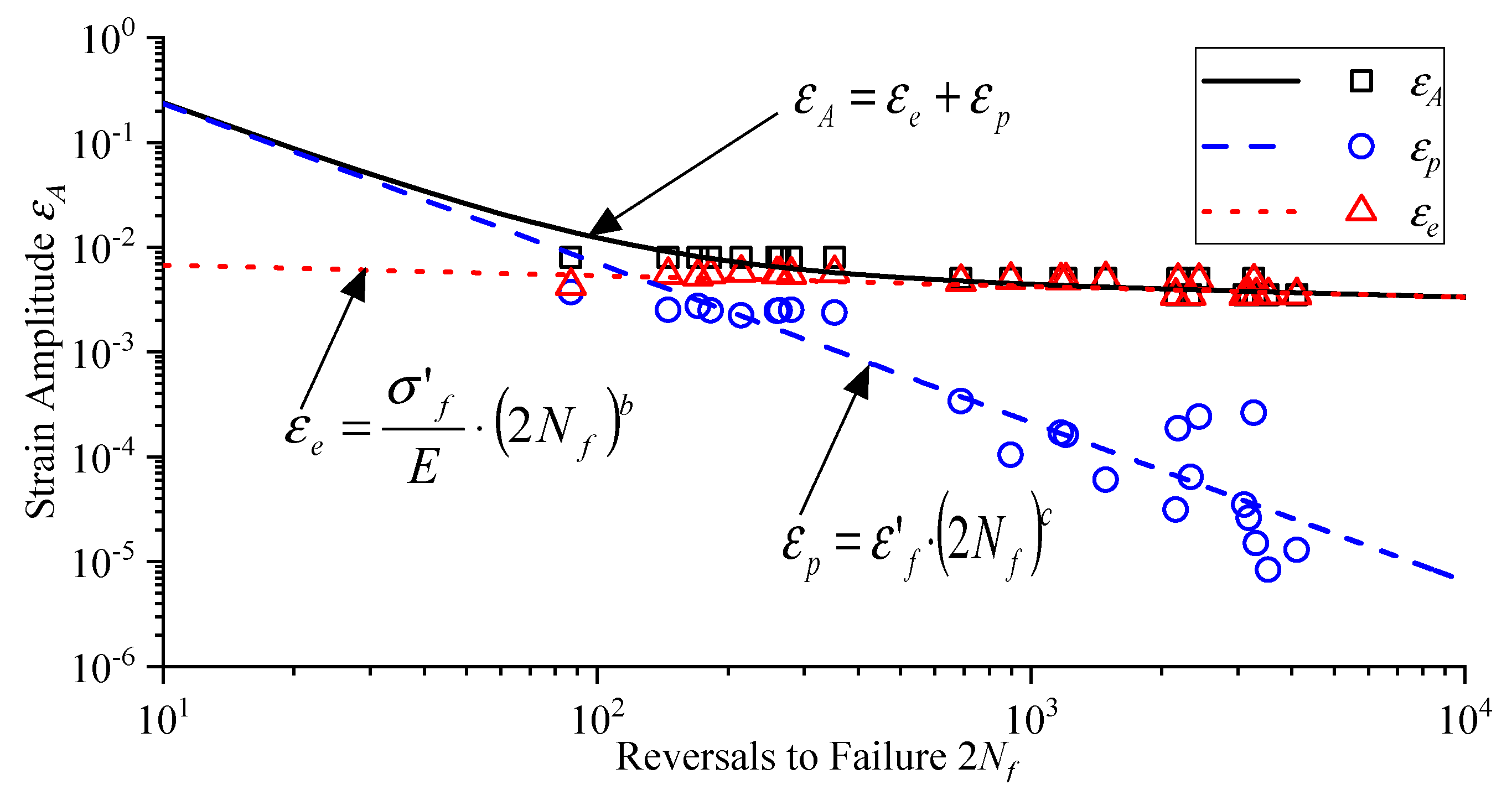
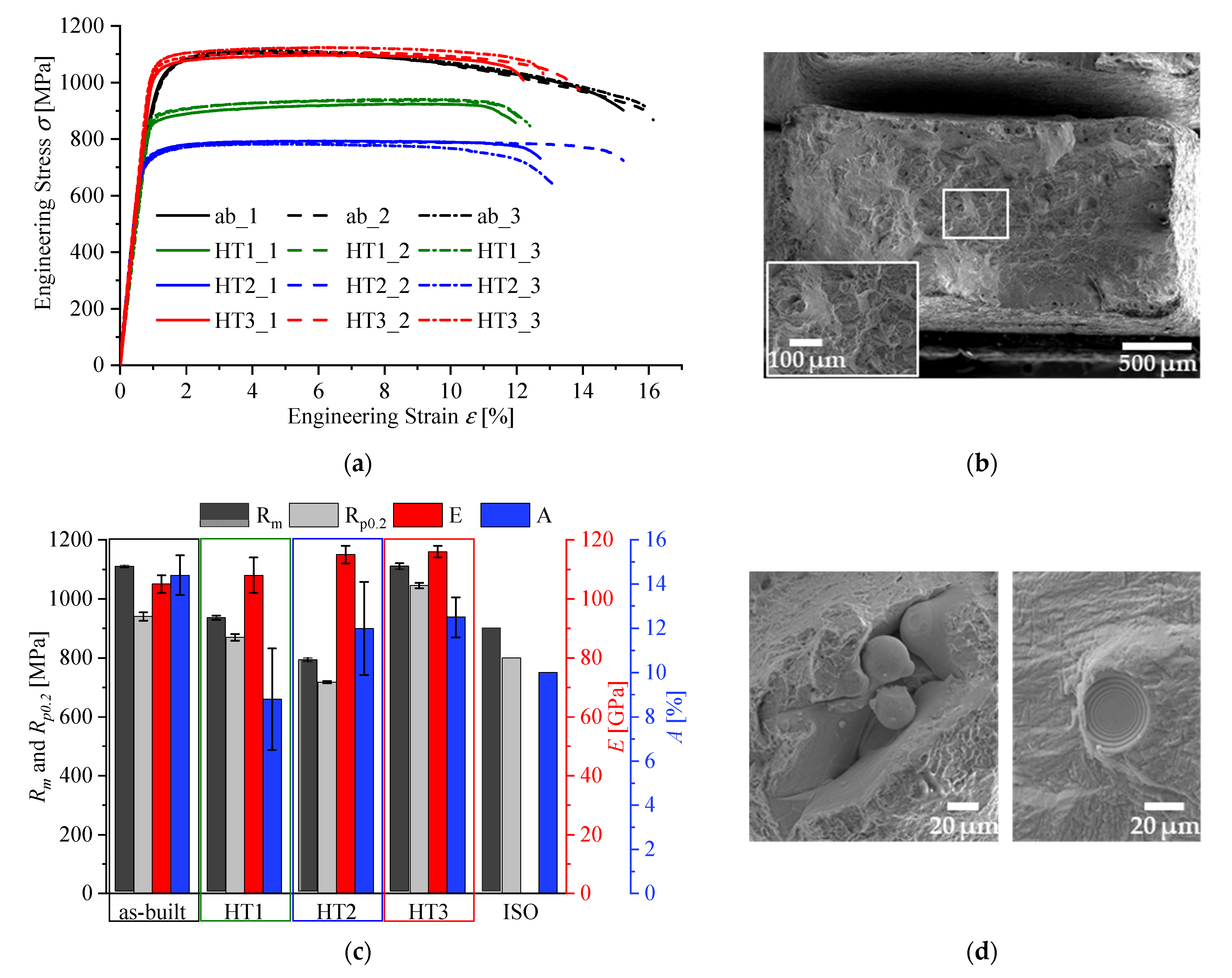
| State | Condition | α Phase | β Phase | Rp0.2 [MPa] | Rm [MPa] | E [GPa] | A [%] | σ′f | b | ε′f | c |
|---|---|---|---|---|---|---|---|---|---|---|---|
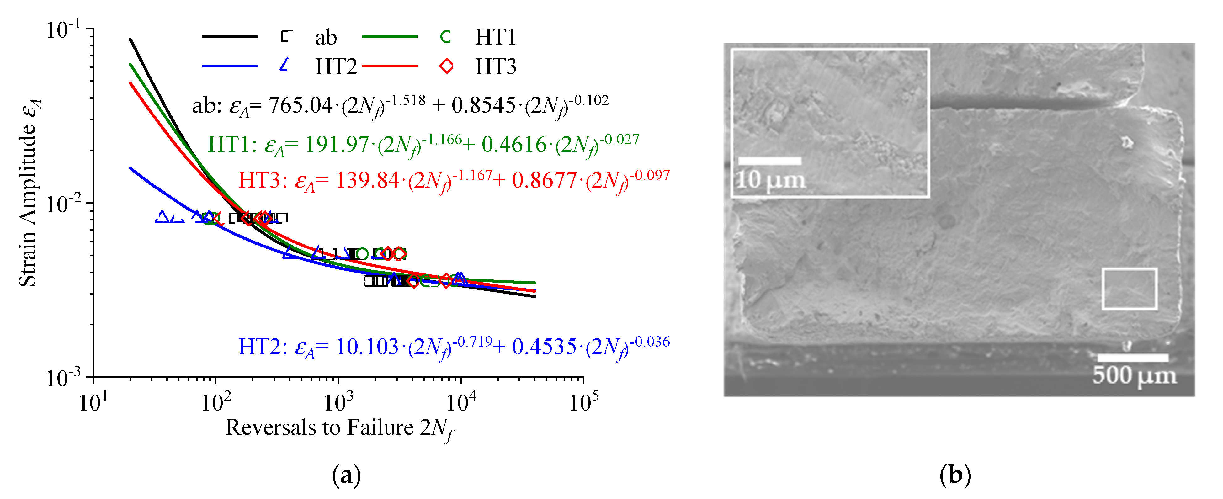
| ab | as-built | 97.0% | 3.0% | 940 ± 14 | 1109 ± 3 | 105 ± 3 | 14.4 ± 0.9 | 89.7 | −0.102 | 765.04 | −1.518 |
| HT1 | 925 °C/4 h | 98.3% | 1.7% | 870 ± 11 | 934 ± 7 | 108 ± 6 | 8.8 ± 2.3 | 49.9 | −0.027 | 191.97 | −1.166 |
| HT2 | 1050 °C/2 h | 97.8% | 2.2% | 718 ± 4 | 791 ± 6 | 115 ± 3 | 12.0 ± 1.1 | 52.2 | −0.036 | 10.103 | −0.719 |
| HT3 | 600 °C/4 h | 97.7% | 2.3% | 1045 ± 9 | 1110 ± 10 | 116 ± 2 | 12.5 ± 0.9 | 100.7 | −0.097 | 139.84 | −1.167 |
| ISO | − | − | − | 800 | 900 | − | 10 | − | − | − | − |
3.2. Mechanical Properties of Ti-6Al-7Nb
3.3. Fracture Behavior
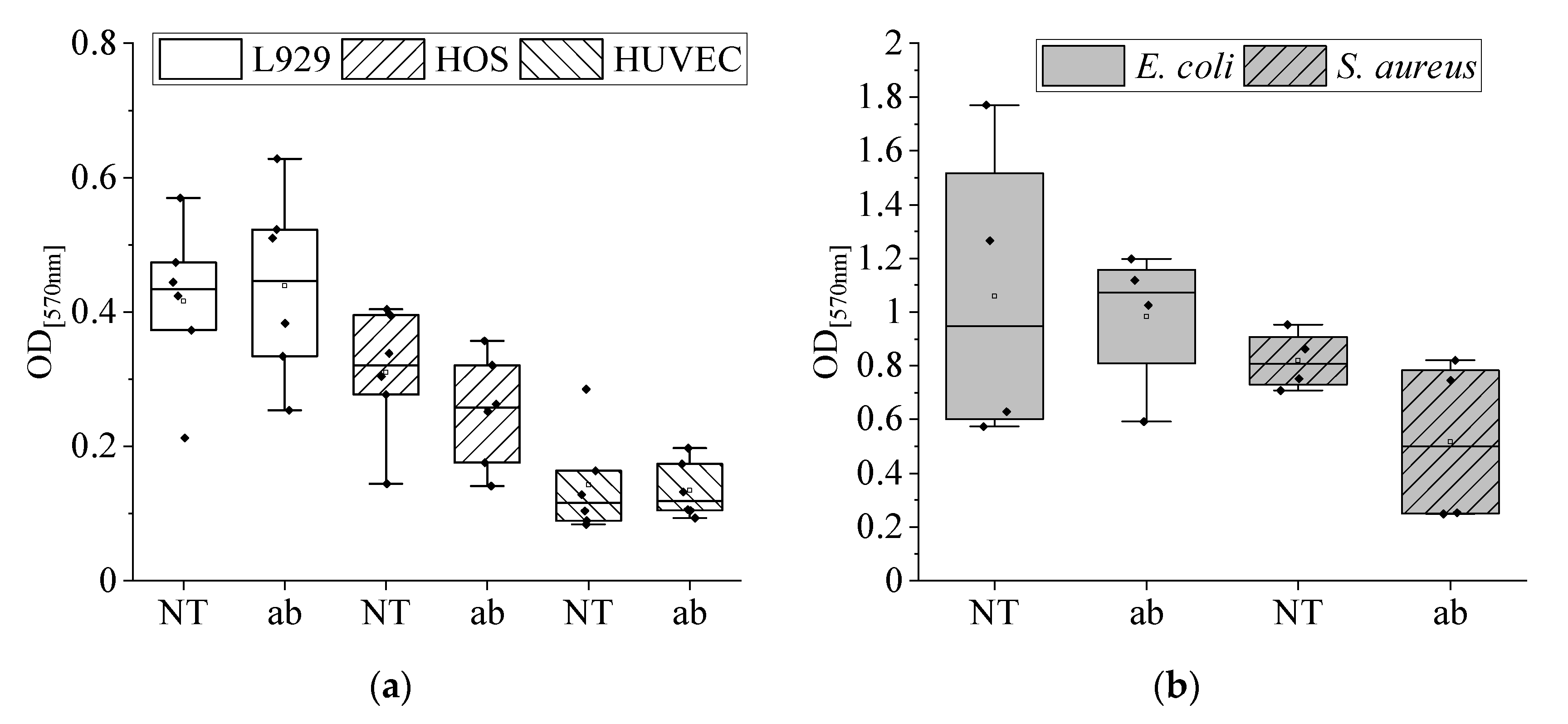
3.4. Characterization of Roughness, Cytocompatibility, and Antibacterial Effects
4. Conclusions
- Ti-6Al-7Nb shows significantly different microstructures in the as-built, stress-relieved, recrystallized, and β-annealed conditions. While the α′/α structure is dominant within the as-built state, the formation and precipitation of the β-phase are manageable by a vacuum heat treatment above 925 °C as analyzed using XRD and EBSD.
- There are significant differences in the monotonic tensile properties of the various conditions. Concerning the ISO values, the as-built and stress-relieved conditions (HT3) are favorable. Tensile and yield strength, as well as breaking elongation, are higher than the demanded values, but the specimens’ dimensions have to be considered. HT1 and HT2 do not fulfill the requirements, probably due to the present β-phase. Heat treatments, such as HT1 and HT2, can significantly affect the microstructure and may tend to soften the lattice structures and decrease the residual stresses and, therefore, lead to significantly reduced tensile strength.
- LCF life is higher for lower strain amplitudes in the heat-treated specimens than in as-built conditions, which can be attributed to decreased residual stresses as well as to microstructural differences. HT2 shows the highest fatigue life for lower strain amplitudes, while the as-built condition has higher service life for higher strain amplitudes. Regarding overall performance, quasi-static results, and LCF performance, stress relief treatment (HT3) is favorable. The material behavior for HCF loading still has to be determined.
- Transgranular facets characterize the fracture surface of the additively processed Ti-6Al-7Nb, confirming the ductile behavior. Small, shallow dimples on quasi-cleavage fracture surfaces are visible. Fatigue fracture surfaces are characterized by fatigue striations and remaining forced rupture surfaces. Defects may have less impact on quasi-static but a high impact on fatigue behavior.
- Both surfaces, the untreated and the blasted, show good biocompatibility in different cell types (fibroblasts, osteosarcoma cells, and endothelial cells). Only a slight anti-proliferative effect was observed for blasted Ti-6Al-7Nb in osteoblasts. An increase in cytokine release of Il-6 was not observed.
- Blasting with high-grade Al2O3 is preferable regarding biocompatibility and anti-bacterial effects. Blasted Ti-6Al-7Nb exhibits an antibacterial effect against S. aureus in comparison with not post-treated Ti-6Al-7Nb. E. coli was able to grow on both surfaces of Ti-6Al-7Nb similarly. On account of remaining aluminum on the blasted surface, glass bead blasting could be taken into consideration.
Author Contributions
Funding
Data Availability Statement
Acknowledgments
Conflicts of Interest
References
- Abdel-Hady Gepreel, M.; Niinomi, M. Biocompatibility of Ti-alloys for long-term implantation. J. Mech. Behav. Biomed. Mater. 2013, 20, 407–415. [Google Scholar] [CrossRef] [PubMed]
- Geetha, M.; Singh, A.K.; Asokamani, R.; Gogia, A.K. Ti based biomaterials, the ultimate choice for orthopaedic implants—A review. Prog. Mater. Sci. 2009, 54, 397–425. [Google Scholar] [CrossRef]
- Long, M.; Rack, H. Titanium alloys in total joint replacement—A materials science perspective. Biomaterials 1998, 19, 1621–1639. [Google Scholar] [CrossRef]
- Kurtz, S.M.; Ong, K.L.; Schmier, J.; Mowat, F.; Saleh, K.; Dybvik, E.; Kärrholm, J.; Garellick, G.; Havelin, L.I.; Furnes, O.; et al. Future clinical and economic impact of revision total hip and knee arthroplasty. J. Bone Jt. Surg. Am. 2007, 89 (Suppl. S3), 144–151. [Google Scholar] [CrossRef]
- Vandenbroucke, B.; Kruth, J.-P. Selective laser melting of biocompatible metals for rapid manufacturing of medical parts. Rapid Prototyp. J. 2007, 13, 196–203. [Google Scholar] [CrossRef]
- Iijima, D. Wear properties of Ti and Ti–6Al–7Nb castings for dental prostheses. Biomaterials 2003, 24, 1519–1524. [Google Scholar] [CrossRef]
- Niinomi, M. Mechanical biocompatibilities of titanium alloys for biomedical applications. J. Mech. Behav. Biomed. Mater. 2008, 1, 30–42. [Google Scholar] [CrossRef]
- Hollander, D.A.; von Walter, M.; Wirtz, T.; Sellei, R.; Schmidt-Rohlfing, B.; Paar, O.; Erli, H.-J. Structural, mechanical and in vitro characterization of individually structured Ti-6Al-4V produced by direct laser forming. Biomaterials 2006, 27, 955–963. [Google Scholar] [CrossRef] [PubMed]
- Murr, L.E.; Quinones, S.A.; Gaytan, S.M.; Lopez, M.I.; Rodela, A.; Martinez, E.Y.; Hernandez, D.H.; Martinez, E.; Medina, F.; Wicker, R.B. Microstructure and mechanical behavior of Ti-6Al-4V produced by rapid-layer manufacturing, for biomedical applications. J. Mech. Behav. Biomed. Mater. 2009, 2, 20–32. [Google Scholar] [CrossRef]
- Kobayashi, E.; Wang, T.J.; Doi, H.; Yoneyama, T.; Hamanaka, H. Mechanical properties and corrosion resistance of Ti-6Al-7Nb alloy dental castings. J. Mater. Sci. Mater. Med. 1998, 9, 567–574. [Google Scholar] [CrossRef]
- Kobayashi, E.; Mochizuki, H.; Doi, H.; Yoneyama, T.; Hanawa, T. Fatigue Life Prediction of Biomedical Titanium Alloys under Tensile/Torsional Stress. Mater. Trans. 2006, 47, 1826–1831. [Google Scholar] [CrossRef][Green Version]
- Srimaneepong, V.; Yoneyama, T.; Kobayashi, E.; Doi, H.; Hanawa, T. Comparative study on torsional strength, ductility and fracture characteristics of laser-welded alpha+beta Ti-6Al-7Nb alloy, CP Titanium and Co-Cr alloy dental castings. Dent. Mater. 2008, 24, 839–845. [Google Scholar] [CrossRef]
- Liu, X.; Chu, P.; Ding, C. Surface modification of titanium, titanium alloys, and related materials for biomedical applications. Mater. Sci. Eng. R Rep. 2004, 47, 49–121. [Google Scholar] [CrossRef]
- Kuroda, D.; Niinomi, M.; Morinaga, M.; Kato, Y.; Yashiro, T. Design and mechanical properties of new β type titanium alloys for implant materials. Mater. Sci. Eng. A Struct. Mater. 1998, 243, 244–249. [Google Scholar] [CrossRef]
- Li, Y.; Yang, C.; Zhao, H.; Qu, S.; Li, X.; Li, Y. New Developments of Ti-Based Alloys for Biomedical Applications. Materials 2014, 7, 1709–1800. [Google Scholar] [CrossRef]
- López, M.; Gutiérrez, A.; Jiménez, J. In vitro corrosion behaviour of titanium alloys without vanadium. Electrochim. Acta 2002, 47, 1359–1364. [Google Scholar] [CrossRef]
- Chlebus, E.; Kuźnicka, B.; Kurzynowski, T.; Dybała, B. Microstructure and mechanical behaviour of Ti―6Al―7Nb alloy produced by selective laser melting. Mater. Charact. 2011, 62, 488–495. [Google Scholar] [CrossRef]
- Surmeneva, M.; Grubova, I.; Glukhova, N.; Khrapov, D.; Koptyug, A.; Volkova, A.; Ivanov, Y.; Cotrut, C.M.; Vladescu, A.; Teresov, A.; et al. New Ti–35Nb–7Zr–5Ta Alloy Manufacturing by Electron Beam Melting for Medical Application Followed by High Current Pulsed Electron Beam Treatment. Metals 2021, 11, 1066. [Google Scholar] [CrossRef]
- Tamilselvi, S.; Raman, V.; Rajendran, N. Corrosion behaviour of Ti–6Al–7Nb and Ti–6Al–4V ELI alloys in the simulated body fluid solution by electrochemical impedance spectroscopy. Electrochim. Acta 2006, 52, 839–846. [Google Scholar] [CrossRef]
- Metikoš-Huković, M.; Kwokal, A.; Piljac, J. The influence of niobium and vanadium on passivity of titanium-based implants in physiological solution. Biomaterials 2003, 24, 3765–3775. [Google Scholar] [CrossRef]
- Schmidt, M.; Merklein, M.; Bourell, D.; Dimitrov, D.; Hausotte, T.; Wegener, K.; Overmeyer, L.; Vollertsen, F.; Levy, G.N. Laser based additive manufacturing in industry and academia. CIRP Ann. 2017, 66, 561–583. [Google Scholar] [CrossRef]
- Bourell, D.; Kruth, J.P.; Leu, M.; Levy, G.; Rosen, D.; Beese, A.M.; Clare, A. Materials for additive manufacturing. CIRP Ann. 2017, 66, 659–681. [Google Scholar] [CrossRef]
- Wohlers, T.T.; Campbell, I.; Diegel, O.; Kowen, J. Wohlers Report 2018. 3D Printing and Additive Manufacturing State of the Industry: Annual Worldwide Progress Report; Wohlers Associates, Inc.: Fort Collins, CO, USA, 2018; ISBN 0991333241. [Google Scholar]
- Attar, H.; Prashanth, K.G.; Chaubey, A.K.; Calin, M.; Zhang, L.C.; Scudino, S.; Eckert, J. Comparison of wear properties of commercially pure titanium prepared by selective laser melting and casting processes. Mater. Lett. 2015, 142, 38–41. [Google Scholar] [CrossRef]
- Dai, N.; Zhang, L.-C.; Zhang, J.; Chen, Q.; Wu, M. Corrosion behavior of selective laser melted Ti-6Al-4 V alloy in NaCl solution. Corros. Sci. 2016, 102, 484–489. [Google Scholar] [CrossRef]
- Yang, Y.; Chen, Y.; Zhang, J.; Gu, X.; Qin, P.; Dai, N.; Li, X.; Kruth, J.-P.; Zhang, L.-C. Improved corrosion behavior of ultrafine-grained eutectic Al-12Si alloy produced by selective laser melting. Mater. Des. 2018, 146, 239–248. [Google Scholar] [CrossRef]
- Melchels, F.P.; Domingos, M.A.; Klein, T.J.; Malda, J.; Bartolo, P.J.; Hutmacher, D.W. Additive manufacturing of tissues and organs. Prog. Polym. Sci. 2012, 37, 1079–1104. [Google Scholar] [CrossRef]
- Herzog, D.; Seyda, V.; Wycisk, E.; Emmelmann, C. Additive manufacturing of metals. Acta Mater. 2016, 117, 371–392. [Google Scholar] [CrossRef]
- Guo, N.; Leu, M.C. Additive manufacturing: Technology, applications and research needs. Front. Mech. Eng. 2013, 8, 215–243. [Google Scholar] [CrossRef]
- Lewandowski, J.J.; Seifi, M. Metal Additive Manufacturing: A Review of Mechanical Properties. Annu. Rev. Mater. Res. 2016, 46, 151–186. [Google Scholar] [CrossRef]
- Yap, C.Y.; Chua, C.K.; Dong, Z.L.; Liu, Z.H.; Zhang, D.Q.; Loh, L.E.; Sing, S.L. Review of selective laser melting: Materials and applications. Appl. Phys. Rev. 2015, 2, 41101. [Google Scholar] [CrossRef]
- Tolosa, I.; Garciandía, F.; Zubiri, F.; Zapirain, F.; Esnaola, A. Study of mechanical properties of AISI 316 stainless steel processed by “selective laser melting”, following different manufacturing strategies. Int. J. Adv. Manuf. Technol. 2010, 51, 639–647. [Google Scholar] [CrossRef]
- Nezhadfar, P.D.; Burford, E.; Anderson-Wedge, K.; Zhang, B.; Shao, S.; Daniewicz, S.R.; Shamsaei, N. Fatigue crack growth behavior of additively manufactured 17-4 PH stainless steel: Effects of build orientation and microstructure. Int. J. Fatigue 2019, 123, 168–179. [Google Scholar] [CrossRef]
- Kluczyński, J.; Śnieżek, L.; Grzelak, K.; Torzewski, J.; Szachogłuchowicz, I.; Wachowski, M.; Łuszczek, J. Crack Growth Behavior of Additively Manufactured 316L Steel-Influence of Build Orientation and Heat Treatment. Materials 2020, 13, 3259. [Google Scholar] [CrossRef]
- Zhang, M.; Sun, C.-N.; Zhang, X.; Wei, J.; Hardacre, D.; Li, H. High cycle fatigue and ratcheting interaction of laser powder bed fusion stainless steel 316L: Fracture behaviour and stress-based modelling. Int. J. Fatigue 2019, 121, 252–264. [Google Scholar] [CrossRef]
- Jerrard, P.G.E.; Hao, L.; Evans, K.E. Experimental investigation into selective laser melting of austenitic and martensitic stainless steel powder mixtures. Proc. Inst. Mech. Eng. B J. Eng. Manuf. 2009, 223, 1409–1416. [Google Scholar] [CrossRef]
- Baufeld, B.; Brandl, E.; van der Biest, O. Wire based additive layer manufacturing: Comparison of microstructure and mechanical properties of Ti–6Al–4V components fabricated by laser-beam deposition and shaped metal deposition. J. Mater. Process. Technol. 2011, 211, 1146–1158. [Google Scholar] [CrossRef]
- Brandl, E. Microstructural and Mechanical Properties of Additive Manufactured Titanium (Ti-6Al-4V) Using Wire. Evaluation with Respect to Additive Processes Using Powder and Aerospace Material Specifications; Dissertation, Brandenburg University of Technology Cottbus-Senftenberg: Cottbus, Germany, 2010; ISBN 978-3-8322-9530-1. [Google Scholar]
- Khorasani, A.; Gibson, I.; Goldberg, M.; Littlefair, G. On the role of different annealing heat treatments on mechanical properties and microstructure of selective laser melted and conventional wrought Ti-6Al-4V. Rapid Prototyp. J. 2017, 23, 295–304. [Google Scholar] [CrossRef]
- Liu, S.; Shin, Y.C. Additive manufacturing of Ti6Al4V alloy: A review. Mater. Des. 2019, 164, 107552. [Google Scholar] [CrossRef]
- Riemer, A.; Richard, H.A. Crack Propagation in Additive Manufactured Materials and Structures. Procedia Struct. Integr. 2016, 2, 1229–1236. [Google Scholar] [CrossRef]
- Leuders, S.; Lieneke, T.; Lammers, S.; Tröster, T.; Niendorf, T. On the fatigue properties of metals manufactured by selective laser melting—The role of ductility. J. Mater. Res. 2014, 29, 1911–1919. [Google Scholar] [CrossRef]
- Tillmann, W.; Hagen, L.; Garthe, K.-U.; Hoyer, K.-P.; Schaper, M. Effect of substrate pre-treatment on the low cycle fatigue performance of tungsten carbide-cobalt coated additive manufactured 316 L substrates. Mater. Werkst. 2020, 51, 1452–1464. [Google Scholar] [CrossRef]
- Romano, S.; Patriarca, L.; Foletti, S.; Beretta, S. LCF behaviour and a comprehensive life prediction model for AlSi10Mg obtained by SLM. Int. J. Fatigue 2018, 117, 47–62. [Google Scholar] [CrossRef]
- Bressan, S.; Ogawa, F.; Itoh, T.; Berto, F. Low cycle fatigue behavior of additively manufactured Ti-6Al-4V under non-proportional and proportional loading. Frat. Integrita Strutt. 2019, 13, 18–25. [Google Scholar] [CrossRef]
- Zhang, S.Q.; Li, S.J.; Jia, M.T.; Prima, F.; Chen, L.J.; Hao, Y.L.; Yang, R. Low-cycle fatigue properties of a titanium alloy exhibiting nonlinear elastic deformation behavior. Acta Mater. 2011, 59, 4690–4699. [Google Scholar] [CrossRef]
- Awd, M.; Tenkamp, J.; Hirtler, M.; Siddique, S.; Bambach, M.; Walther, F. Comparison of Microstructure and Mechanical Properties of Scalmalloy® Produced by Selective Laser Melting and Laser Metal Deposition. Materials 2017, 11, 17. [Google Scholar] [CrossRef]
- Leuders, S.; Thöne, M.; Riemer, A.; Niendorf, T.; Tröster, T.; Richard, H.A.; Maier, H.J. On the mechanical behaviour of titanium alloy TiAl6V4 manufactured by selective laser melting: Fatigue resistance and crack growth performance. Int. J. Fatigue 2013, 48, 300–307. [Google Scholar] [CrossRef]
- Wycisk, E.; Siddique, S.; Herzog, D.; Walther, F.; Emmelmann, C. Fatigue Performance of Laser Additive Manufactured Ti–6Al–4V in Very High Cycle Fatigue Regime up to 109 Cycles. Front. Mater. 2015, 2, 72. [Google Scholar] [CrossRef]
- Polozov, I.; Sufiiarov, V.; Popovich, A.; Masaylo, D.; Grigoriev, A. Synthesis of Ti-5Al, Ti-6Al-7Nb, and Ti-22Al-25Nb alloys from elemental powders using powder-bed fusion additive manufacturing. J. Alloy. Compd. 2018, 763, 436–445. [Google Scholar] [CrossRef]
- Affolter, C.; Thorwarth, G.; Arabi-Hashemi, A.; Müller, U.; Weisse, B. Ductile Compressive Behavior of Biomedical Alloys. Metals 2020, 10, 60. [Google Scholar] [CrossRef]
- Xu, C.; Sikan, F.; Atabay, S.E.; Muñiz-Lerma, J.A.; Sanchez-Mata, O.; Wang, X.; Brochu, M. Microstructure and mechanical behavior of as-built and heat-treated Ti–6Al–7Nb produced by laser powder bed fusion. Mater. Sci. Eng. A Struct. Mater. 2020, 793, 139978. [Google Scholar] [CrossRef]
- Hein, M.; Hoyer, K.-P.; Schaper, M. Additively processed TiAl6Nb7 alloy for biomedical applications. Mater. Werkst. 2021, 52, 703–716. [Google Scholar] [CrossRef]
- Bergmann, G.; Bender, A.; Dymke, J.; Duda, G.; Damm, P. Standardized Loads Acting in Hip Implants. PLoS ONE 2016, 11, e0155612. [Google Scholar] [CrossRef]
- Bergmann, G.; Graichen, F.; Rohlmann, A.; Bender, A.; Heinlein, B.; Duda, G.N.; Heller, M.O.; Morlock, M.M. Realistic loads for testing hip implants. Biomed. Mater. Eng. 2010, 20, 65–75. [Google Scholar] [CrossRef] [PubMed]
- Sallica-Leva, E.; Caram, R.; Jardini, A.L.; Fogagnolo, J.B. Ductility improvement due to martensite α’ decomposition in porous Ti-6Al-4V parts produced by selective laser melting for orthopedic implants. J. Mech. Behav. Biomed. Mater. 2016, 54, 149–158. [Google Scholar] [CrossRef] [PubMed]
- Tao, P.; Li, H.; Huang, B.; Hu, Q.; Gong, S.; Xu, Q. Tensile behavior of Ti-6Al-4V alloy fabricated by selective laser melting: Effects of microstructures and as-built surface quality. China Foundry 2018, 15, 243–252. [Google Scholar] [CrossRef]
- Gil Mur, F.X.; Rodríguez, D.; Planell, J.A. Influence of tempering temperature and time on the α′-Ti-6Al-4V martensite. J. Alloy. Compd. 1996, 234, 287–289. [Google Scholar] [CrossRef]
- Liang, Z.; Sun, Z.; Zhang, W.; Wu, S.; Chang, H. The effect of heat treatment on microstructure evolution and tensile properties of selective laser melted Ti6Al4V alloy. J. Alloy. Compd. 2019, 782, 1041–1048. [Google Scholar] [CrossRef]
- Donachie, M.J. Titanium. A Technical Guide, 2nd ed.; ASM International: Materials Park, OH, USA, 2000; ISBN 9780871706867. [Google Scholar]
- Bachmann, F.; Hielscher, R.; Schaeben, H. Texture Analysis with MTEX—Free and Open Source Software Toolbox. Solid State Phenom. 2010, 160, 63–68. [Google Scholar] [CrossRef]
- Plumtree, A. Cyclic stress–Strain response and substructure. Int. J. Fatigue 2001, 23, 799–805. [Google Scholar] [CrossRef]
- Rice, R.C. Fatigue Design Handbook, 2nd ed.; Society of Automotive Engineers: Warrendale, PA, USA, 1988; ISBN 9780898830118. [Google Scholar]
- Skelton, R.P.; Maier, H.J.; Christ, H.-J. The Bauschinger effect, Masing model and the Ramberg–Osgood relation for cyclic deformation in metals. Mater. Sci. Eng. A Struct. Mater. 1997, 238, 377–390. [Google Scholar] [CrossRef]
- Nieslony, A.; Dsoki, C.; Kaufmann, H.; Krug, P. New method for evaluation of the Manson–Coffin–Basquin and Ramberg–Osgood equations with respect to compatibility. Int. J. Fatigue 2008, 30, 1967–1977. [Google Scholar] [CrossRef]
- Basquin, O.H. The exponential law of endurance tests. Am. Soc. Test. Mater. 1910, 10, 625–630. [Google Scholar]
- Coffin, L.F. A Study of the Effects of Cyclic Thermal Stresses on a Ductile Metal. Trans. Am. Soc. Mech. 1954, 76, 931–950. [Google Scholar]
- Manson, S.S. Behavior of Materials Under Conditions of Thermal Stress; National Advisory Committee for Aeronautics: Edwards, CA, USA, 1953. [Google Scholar]
- Suresh, S. Fatigue of Materials, 2nd ed.; Reprint; Cambridge Univ. Press: Cambridge, UK, 2004; ISBN 978-0-521-57847-9. [Google Scholar]
- ASM International. Fatigue and Fracture, 10th ed.; 3. Print; ASM International: Materials Park, OH, USA, 2002; ISBN 9780871703859. [Google Scholar]
- Schupbach, P.; Glauser, R.; Bauer, S. Al2O3 Particles on Titanium Dental Implant Systems following Sandblasting and Acid-Etching Process. Int. J. Biomater. 2019, 2019, 6318429. [Google Scholar] [CrossRef]
- Le Guéhennec, L.; Soueidan, A.; Layrolle, P.; Amouriq, Y. Surface treatments of titanium dental implants for rapid osseointegration. Dent. Mater. 2007, 23, 844–854. [Google Scholar] [CrossRef] [PubMed]
- Wennerberg, A.; Albrektsson, T.; Chrcanovic, B. Long-term clinical outcome of implants with different surface modifications. Eur. J. Oral Implantol. 2018, 11 (Suppl. S1), S123–S136. [Google Scholar]
- Yuda, A.W.; Supriadi, S.; Saragih, A.S. Surface modification of Ti-alloy based bone implant by sandblasting. In The 4th Biomedical Engineering’s Recent Progress in Biomaterials, Drugs Development, Health, and Medical Devices, Proceedings of the International Symposium of Biomedical Engineering (ISBE), Padang, Indonesia, 22–24 July 2019; AIP Publishing: Melville, NY, USA, 2019; p. 20015. [Google Scholar]
- Yurttutan, M.E.; Keskin, A. Evaluation of the effects of different sand particles that used in dental implant roughened for osseointegration. BMC Oral Health 2018, 18, 47. [Google Scholar] [CrossRef]
- Gillies, R.J.; Didier, N.; Denton, M. Determination of cell number in monolayer cultures. Anal. Biochem. 1986, 159, 109–113. [Google Scholar] [CrossRef]
- Sercombe, T.; Jones, N.; Day, R.; Kop, A. Heat treatment of Ti-6Al-7Nb components produced by selective laser melting. Rapid Prototyp. J. 2008, 14, 300–304. [Google Scholar] [CrossRef]
- Ajeel, S.A.; Alzubaydi, T.L.; Swadi, A.K. Influence of Heat Treatment Conditions on Microstructure of Ti-6Al-7Nb Alloy as Used Surgical Implant Materials. Eng. Technol. 2007, 25, 431–442. [Google Scholar]
- DebRoy, T.; Wei, H.L.; Zuback, J.S.; Mukherjee, T.; Elmer, J.W.; Milewski, J.O.; Beese, A.M.; Wilson-Heid, A.; De, A.; Zhang, W. Additive manufacturing of metallic components—Process, structure and properties. Prog. Mater. Sci. 2018, 92, 112–224. [Google Scholar] [CrossRef]
- Körner, C. Additive manufacturing of metallic components by selective electron beam melting—A review. Int. Mater. Rev. 2016, 61, 361–377. [Google Scholar] [CrossRef]
- Banerjee, S.; Mukhopadhyay, P. Phase Transformations. Examples from Titanium and Zirconium Alloys; Elsevier: Amsterdam, The Netherlands; Oxford, UK, 2007; ISBN 9780080421452. [Google Scholar]
- Thijs, L.; Verhaeghe, F.; Craeghs, T.; van Humbeeck, J.; Kruth, J.-P. A study of the microstructural evolution during selective laser melting of Ti–6Al–4V. Acta Mater. 2010, 58, 3303–3312. [Google Scholar] [CrossRef]
- Kobryn, P.; Semiatin, S. Microstructure and texture evolution during solidification processing of Ti–6Al–4V. J. Mater. Process. Technol. 2003, 135, 330–339. [Google Scholar] [CrossRef]
- Lütjering, G. Influence of processing on microstructure and mechanical properties of (α + β) titanium alloys. Mater. Sci. Eng. A Struct. Mater. 1998, 243, 32–45. [Google Scholar] [CrossRef]
- Lütjering, G.; Williams, J.C. Titanium, 2nd ed.; Springer: Berlin, Germany, 2007; ISBN 9783540713975. [Google Scholar]
- Burgers, W.G. On the process of transition of the cubic-body-centered modification into the hexagonal-close-packed modification of zirconium. Physica 1934, 1, 561–586. [Google Scholar] [CrossRef]
- Peters, M.; Leyens, C. Titan und Titanlegierungen, 3rd ed.; Wiley-VCH: Weinheim, Germany, 2002; ISBN 9783527611089. [Google Scholar]
- Murr, L.E.; Gaytan, S.M.; Ramirez, D.A.; Martinez, E.; Hernandez, J.; Amato, K.N.; Shindo, P.W.; Medina, F.R.; Wicker, R.B. Metal Fabrication by Additive Manufacturing Using Laser and Electron Beam Melting Technologies. J. Mater. Sci. Technol. 2012, 28, 1–14. [Google Scholar] [CrossRef]
- Rehme, O. Cellular Design for Laser Freeform Fabrication, 1st ed.; Cuvillier Verlag: Göttingen, Germany, 2010; ISBN 9783869552736. [Google Scholar]
- Sieniawski, J.; Ziaja, W.; Kubiak, K.; Motyk, M. Microstructure and Mechanical Properties of High Strength Two-Phase Titanium Alloys. In Titanium Alloys—Advances in Properties Control; Sieniawski, J., Ziaja, W., Eds.; InTech: Rijeka, Croatia, 2014; ISBN 978-953-51-1110-8. [Google Scholar]
- Bolzoni, L.; Weissgaerber, T.; Kieback, B.; Ruiz-Navas, E.M.; Gordo, E. Mechanical behaviour of pressed and sintered CP Ti and Ti-6Al-7Nb alloy obtained from master alloy addition powder. J. Mech. Behav. Biomed. Mater. 2013, 20, 149–161. [Google Scholar] [CrossRef] [PubMed]
- ISO 5832-11:2014; Chirurgische Implantate—Metallische Werkstoffe—Teil 11: Titan Aluminium-6 Niob-7 Knetlegierung. DIN Deutsches Institut für Normung e. V.: Berlin, Germany, 2015.
- Shunmugavel, M.; Polishetty, A.; Littlefair, G. Microstructure and Mechanical Properties of Wrought and Additive Manufactured Ti-6Al-4V Cylindrical Bars. Procedia Technol. 2015, 20, 231–236. [Google Scholar] [CrossRef]
- Attar, H.; Calin, M.; Zhang, L.C.; Scudino, S.; Eckert, J. Manufacture by selective laser melting and mechanical behavior of commercially pure titanium. Mater. Sci. Eng. A Struct. Mater. 2014, 593, 170–177. [Google Scholar] [CrossRef]
- Gorny, B.; Niendorf, T.; Lackmann, J.; Thoene, M.; Troester, T.; Maier, H.J. In situ characterization of the deformation and failure behavior of non-stochastic porous structures processed by selective laser melting. Mater. Sci. Eng. A Struct. Mater. 2011, 528, 7962–7967. [Google Scholar] [CrossRef]
- Blochwitz, C.; Jacob, S.; Tirschler, W. Grain orientation effects on the growth of short fatigue cracks in austenitic stainless steel. Mater. Sci. Eng. A Struct. Mater. 2008, 496, 59–66. [Google Scholar] [CrossRef]
- Rao, K.T.V.; Yu, W.; Ritchie, R.O. Fatigue crack propagation in aluminum-lithium alloy 2090: Part II. small crack behavior. Metall. Mater. Trans. A Phys. Metall. Mater. Sci. 1988, 19, 563–569. [Google Scholar] [CrossRef]
- Riemer, A.; Leuders, S.; Thöne, M.; Richard, H.A.; Tröster, T.; Niendorf, T. On the fatigue crack growth behavior in 316 L stainless steel manufactured by selective laser melting. Eng. Fract. Mech. 2014, 120, 15–25. [Google Scholar] [CrossRef]
- Zerbst, U.; Bruno, G.; Buffiere, J.-Y.; Wegener, T.; Niendorf, T.; Wu, T.; Zhang, X.; Kashaev, N.; Meneghetti, G.; Hrabe, N.; et al. Damage tolerant design of additively manufactured metallic components subjected to cyclic loading: State of the art and challenges. Prog. Mater. Sci. 2021, 121, 100786. [Google Scholar] [CrossRef] [PubMed]
- Afkhami, S.; Dabiri, M.; Alavi, S.H.; Björk, T.; Salminen, A. Fatigue characteristics of steels manufactured by selective laser melting. Int. J. Fatigue 2019, 122, 72–83. [Google Scholar] [CrossRef]
- Schweikl, H.; Müller, R.; Englert, C.; Hiller, K.-A.; Kujat, R.; Nerlich, M.; Schmalz, G. Proliferation of osteoblasts and fibroblasts on model surfaces of varying roughness and surface chemistry. J. Mater. Sci. Mater. Med. 2007, 18, 1895–1905. [Google Scholar] [CrossRef] [PubMed]
- Jeffery, E.H.; Abreo, K.; Burgess, E.; Cannata, J.; Greger, J.L. Systemic aluminum toxicity: Effects on bone, hematopoietic tissue, and kidney. J. Toxicol. Environ. Health 1996, 48, 649–665. [Google Scholar] [CrossRef] [PubMed]
- Daley, B.; Doherty, A.T.; Fairman, B.; Case, C.P. Wear debris from hip or knee replacements causes chromosomal damage in human cells in tissue culture. J. Bone Jt. Surg. Br. 2004, 86-B, 598–606. [Google Scholar] [CrossRef]
- Weng, Y.; Liu, H.; Ji, S.; Huang, Q.; Wu, H.; Li, Z.; Wu, Z.; Wang, H.; Tong, L.; Fu, R.K.; et al. A promising orthopedic implant material with enhanced osteogenic and antibacterial activity: Al2O3-coated aluminum alloy. Appl. Surf. Sci. 2018, 457, 1025–1034. [Google Scholar] [CrossRef]
- Cattoni, D.; Ferrari, C.; Lebedev, L.; Pazos, L.; Svoboda, H. Effect of Blasting on the Fatigue Life of Ti-6Al-7Nb and Stainless Steel AISI 316 LVM. Proc. Mater. Sci. 2012, 1, 461–468. [Google Scholar] [CrossRef]
- Javier Gil, F.; Planell, J.A.; Padrós, A.; Aparicio, C. The effect of shot blasting and heat treatment on the fatigue behavior of titanium for dental implant applications. Dent. Mater. 2007, 23, 486–491. [Google Scholar] [CrossRef] [PubMed]
- Pazos, L.; Corengia, P.; Svoboda, H. Effect of surface treatments on the fatigue life of titanium for biomedical applications. J. Mech. Behav. Biomed. Mater. 2010, 3, 416–424. [Google Scholar] [CrossRef] [PubMed]


Publisher’s Note: MDPI stays neutral with regard to jurisdictional claims in published maps and institutional affiliations. |
© 2022 by the authors. Licensee MDPI, Basel, Switzerland. This article is an open access article distributed under the terms and conditions of the Creative Commons Attribution (CC BY) license (https://creativecommons.org/licenses/by/4.0/).
Share and Cite
Hein, M.; Kokalj, D.; Lopes Dias, N.F.; Stangier, D.; Oltmanns, H.; Pramanik, S.; Kietzmann, M.; Hoyer, K.-P.; Meißner, J.; Tillmann, W.; et al. Low Cycle Fatigue Performance of Additively Processed and Heat-Treated Ti-6Al-7Nb Alloy for Biomedical Applications. Metals 2022, 12, 122. https://doi.org/10.3390/met12010122
Hein M, Kokalj D, Lopes Dias NF, Stangier D, Oltmanns H, Pramanik S, Kietzmann M, Hoyer K-P, Meißner J, Tillmann W, et al. Low Cycle Fatigue Performance of Additively Processed and Heat-Treated Ti-6Al-7Nb Alloy for Biomedical Applications. Metals. 2022; 12(1):122. https://doi.org/10.3390/met12010122
Chicago/Turabian StyleHein, Maxwell, David Kokalj, Nelson Filipe Lopes Dias, Dominic Stangier, Hilke Oltmanns, Sudipta Pramanik, Manfred Kietzmann, Kay-Peter Hoyer, Jessica Meißner, Wolfgang Tillmann, and et al. 2022. "Low Cycle Fatigue Performance of Additively Processed and Heat-Treated Ti-6Al-7Nb Alloy for Biomedical Applications" Metals 12, no. 1: 122. https://doi.org/10.3390/met12010122
APA StyleHein, M., Kokalj, D., Lopes Dias, N. F., Stangier, D., Oltmanns, H., Pramanik, S., Kietzmann, M., Hoyer, K.-P., Meißner, J., Tillmann, W., & Schaper, M. (2022). Low Cycle Fatigue Performance of Additively Processed and Heat-Treated Ti-6Al-7Nb Alloy for Biomedical Applications. Metals, 12(1), 122. https://doi.org/10.3390/met12010122