
Dissimilar Non-Ferrous Metal Welding: An Insight on Experimental and Numerical Analysis


Abstract
1. Introduction
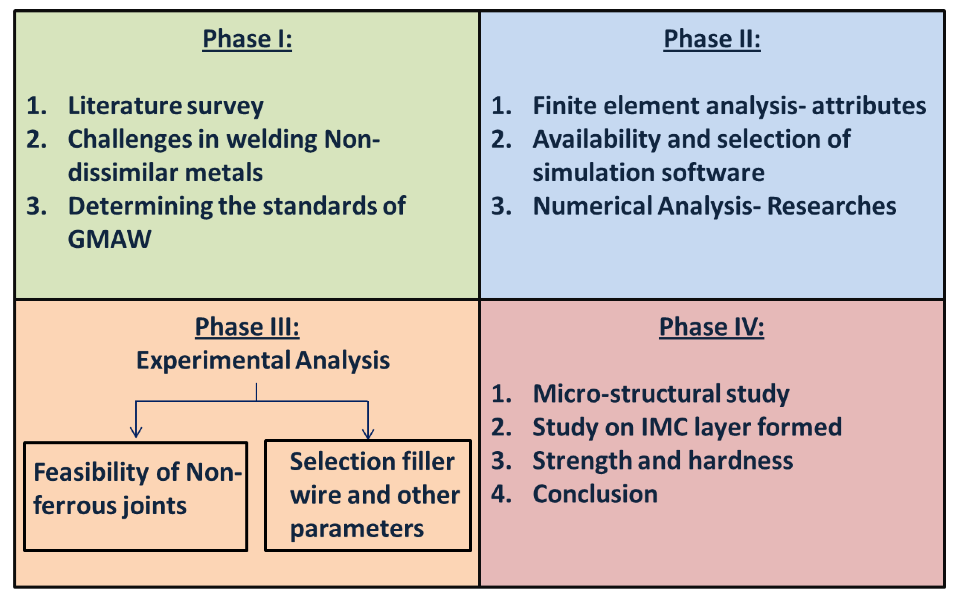
Architecture of the Review
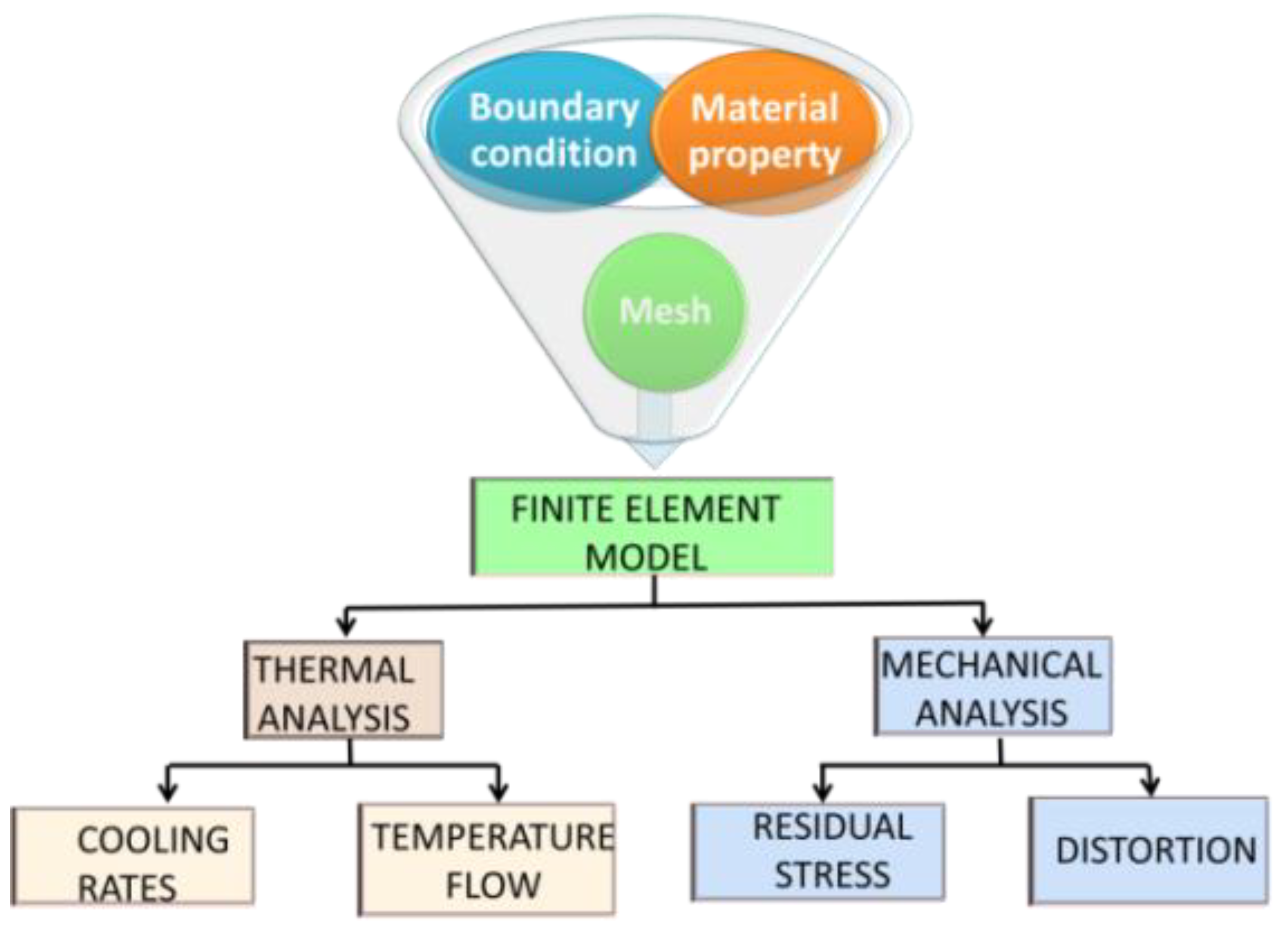
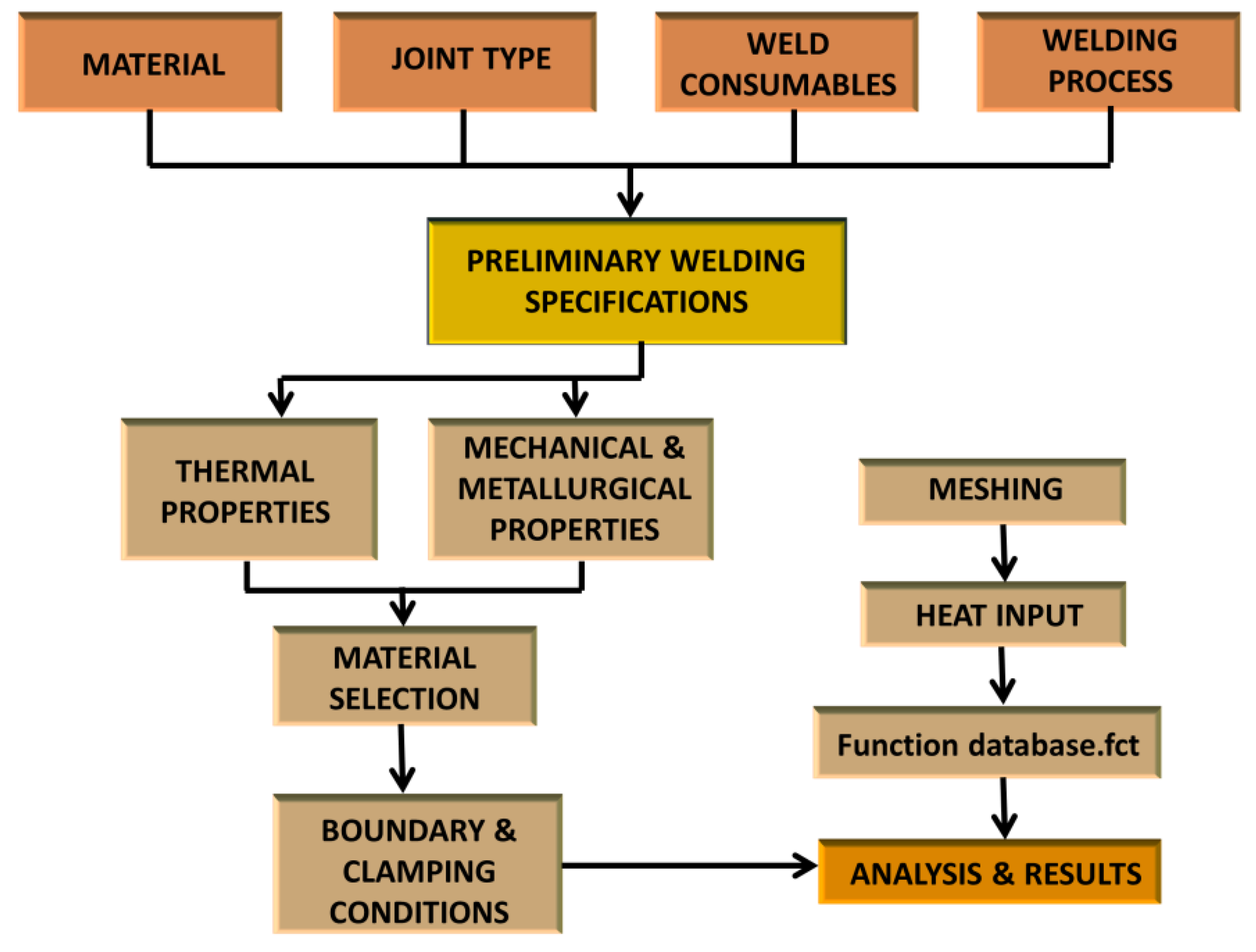
2. Finite Element Analysis (FEA)
2.1. Mesh
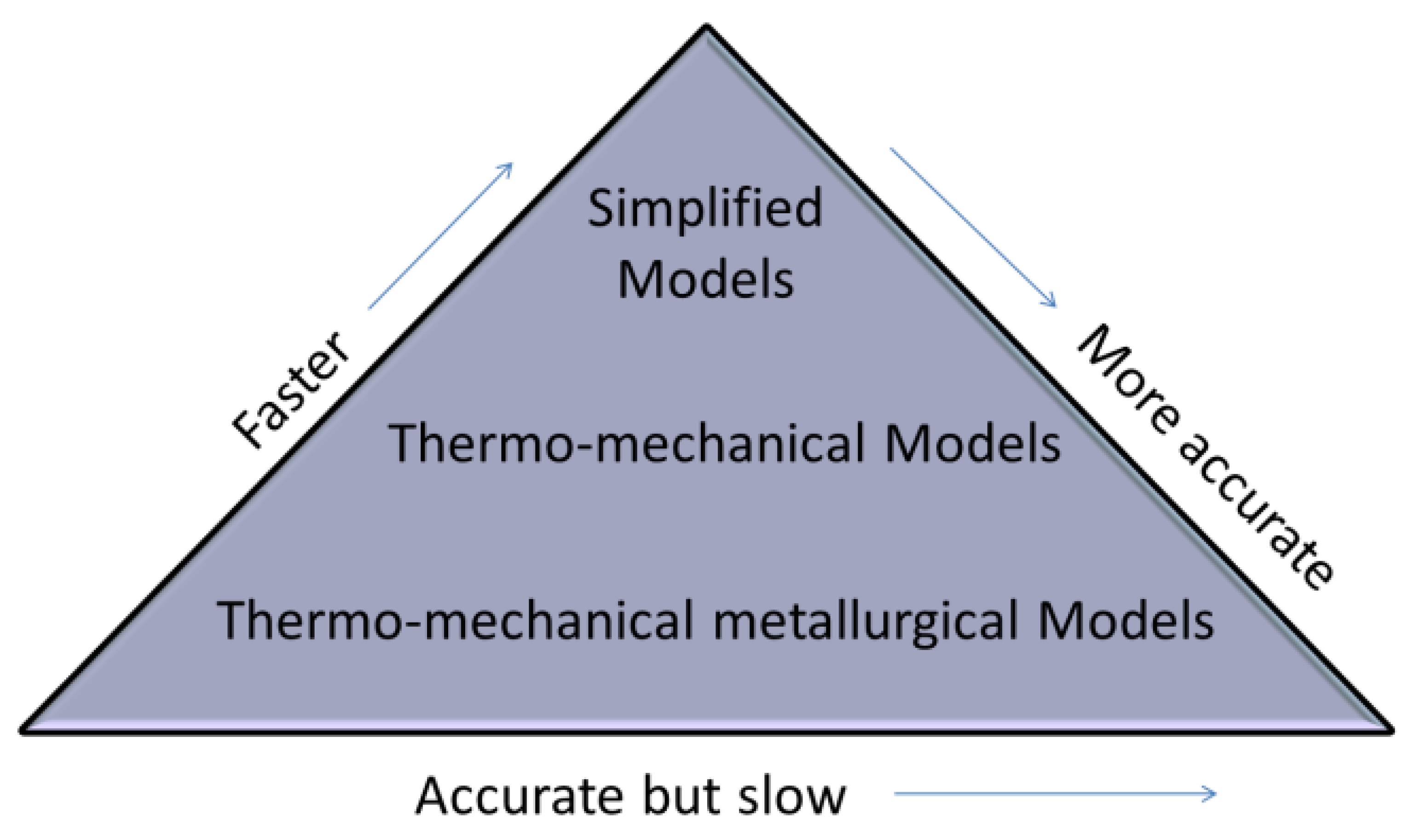
2.2. Models
2.2.1. Isotropic Hardening
2.2.2. Kinematic Hardening
3. Simulation Software
4. Nonferrous Dissimilar Welding
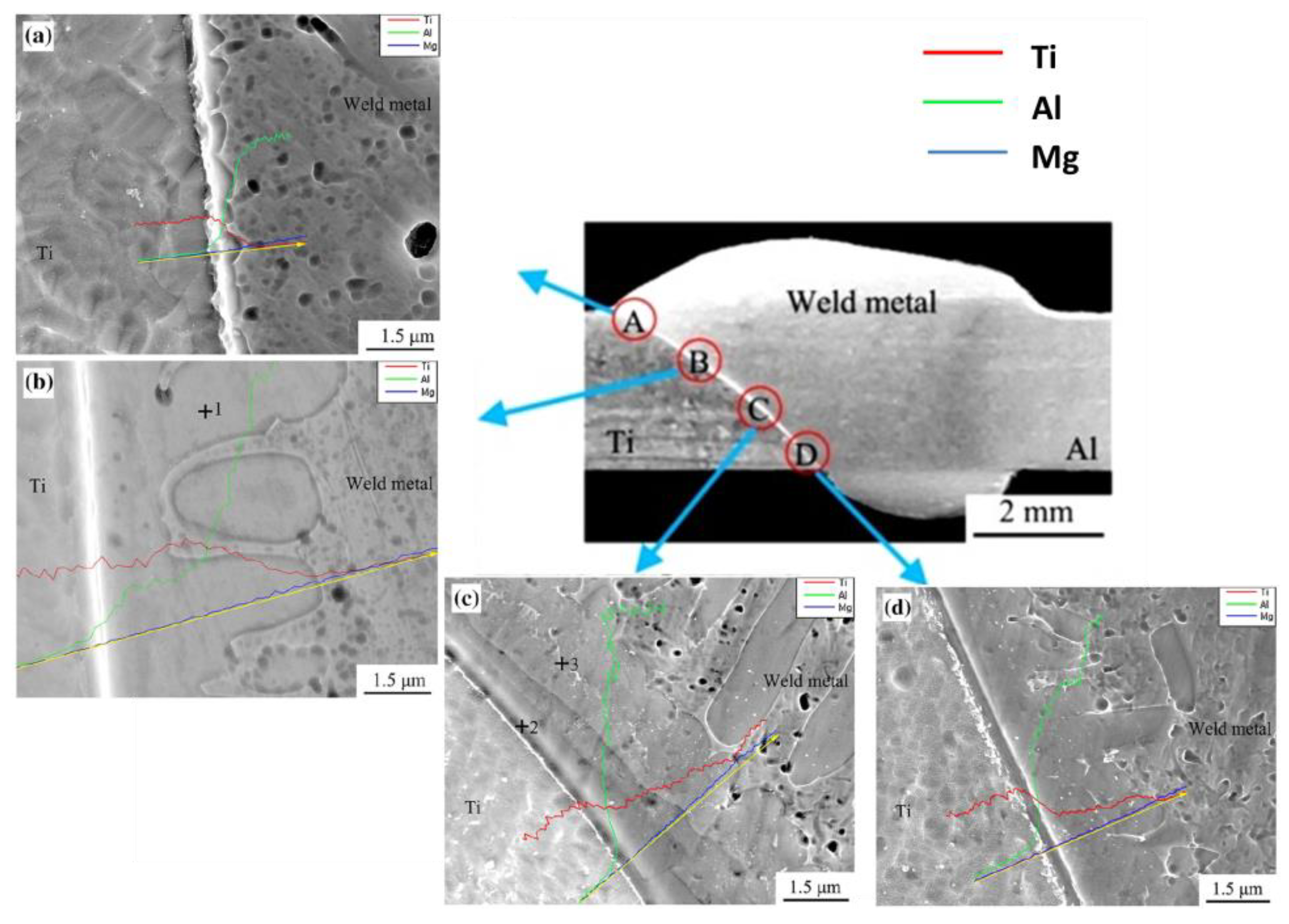
4.1. Welding of Titanium to Aluminum
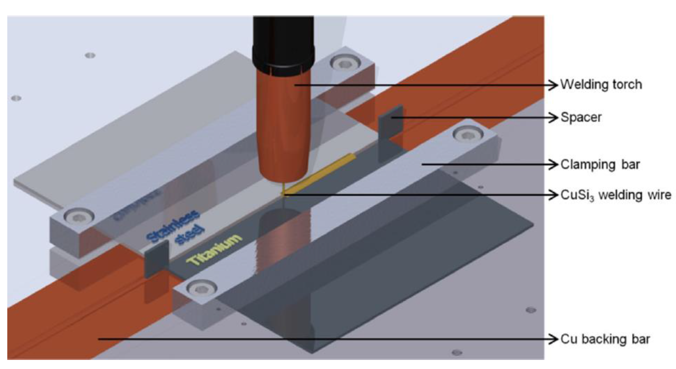
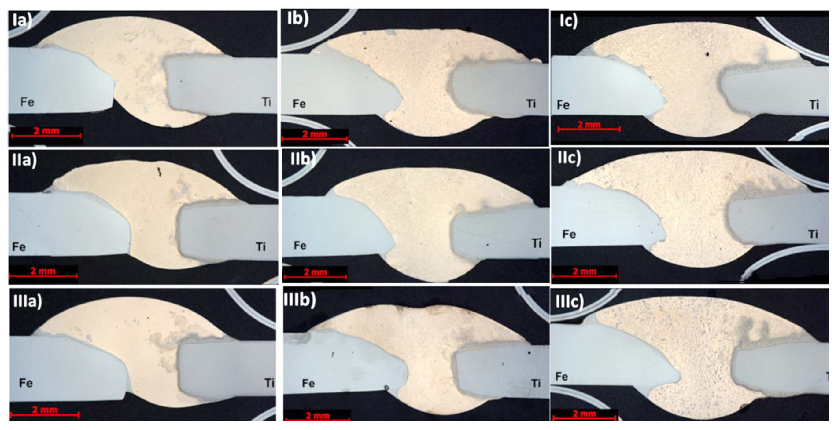
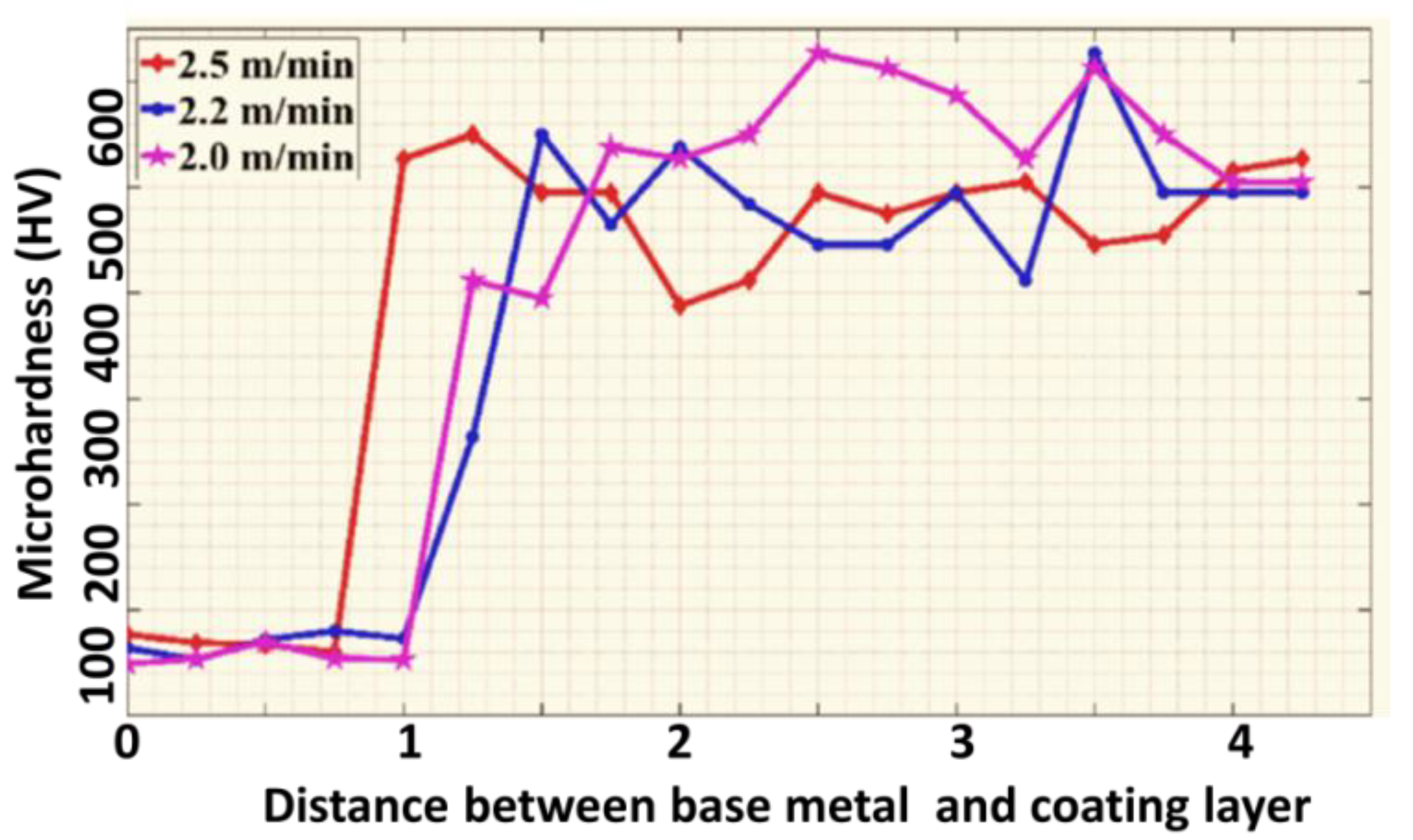
4.2. Welding of Titanium to Steel
4.3. Welding of Titanium to Nickel
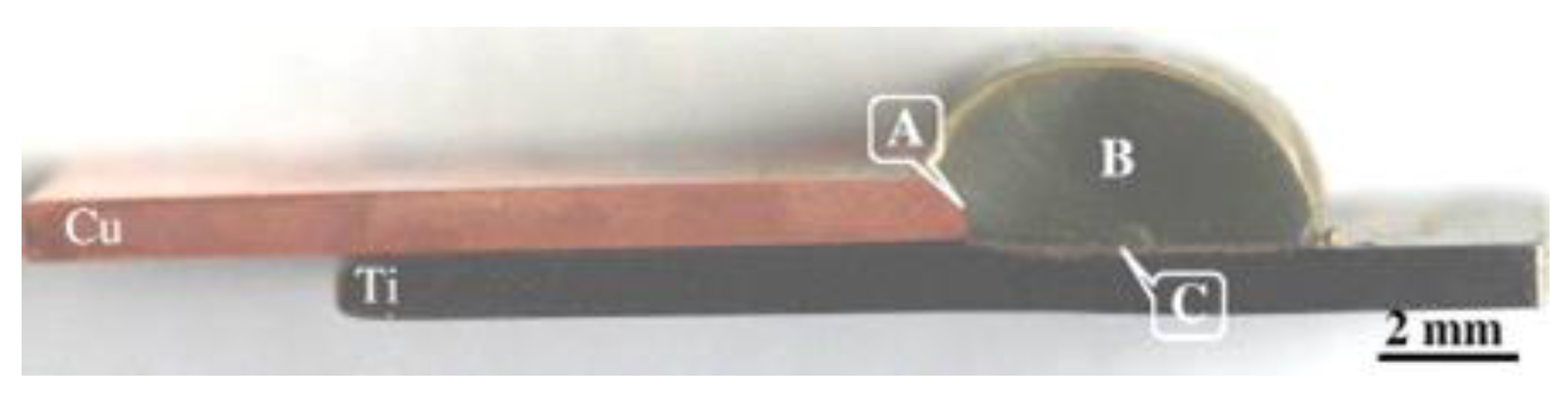
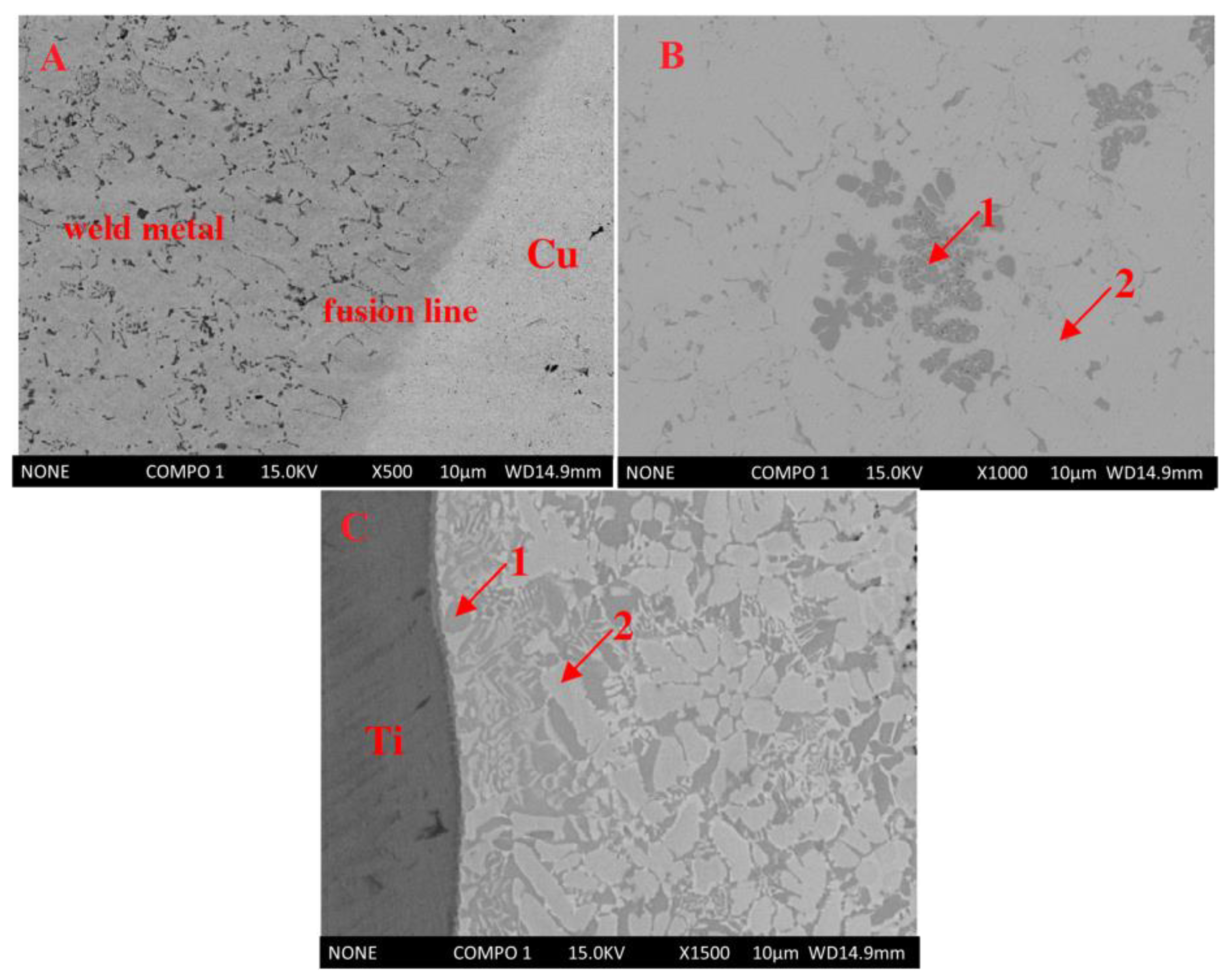
4.4. Welding of Titanium to Copper
4.5. Welding of Copper to Aluminum
4.6. Welding of Copper to Nickel
4.7. Welding of Copper to Brass
4.8. Welding of Cobalt to Nickel
4.9. Welding of Magnesium to Aluminum
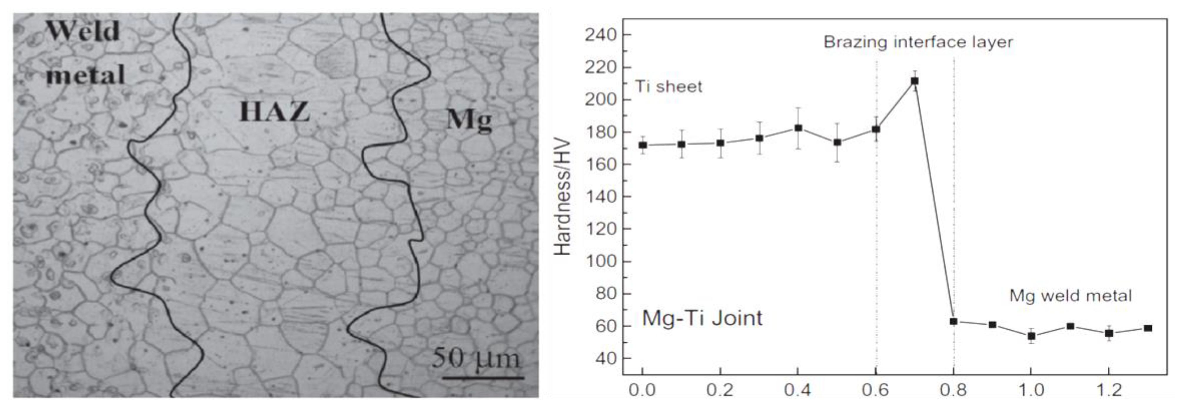
4.10. Welding of Magnesium to Titanium
5. Conclusions
- When welding dissimilar nonferrous metals, various specifications must be considered, including the base metal characteristics, electrode selection, and welding phase selection. The traditional GMAW process is not recommended for welding non-ferrous metals because the heat input control and arc stability are inadequate for this purpose.
- During welding of dissimilar non-ferrous and ferrous metals, deciding the welding cycle is as important as selecting the appropriate electrode that to be used in the welding process. Specifically while welding different non-ferrous metals, the welding method should be deliberately selected as heat input affects shrinkage and element relocation. With its high stability and tolerance, adaptive GMAW can minimize the shrinkage and residual stress induced by thermal coefficient variations.
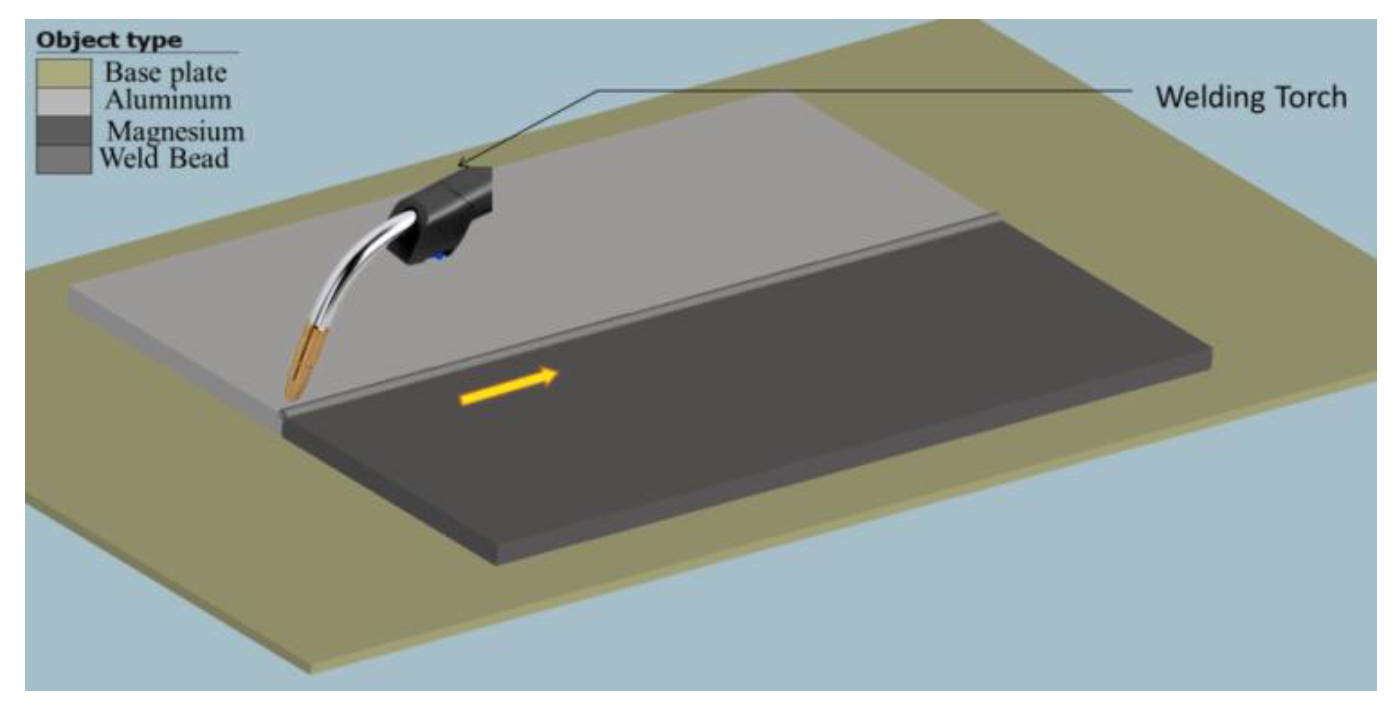
- AZ31 magnesium and aluminum were effectively welded using an adaptive GMAW. The hardness in the intermetallic layer of the welded metals was increased by increasing the temperature and duration of the heat input. Similarly, Cu–Ni joints can be welded by GMAW using any nickel-based filler wires.
- CMT welding enables dissimilar metal joining of Ti & Cu; Ti & Mg; Cu & Al, and Mg & Al respectively.
- The research aspects that are not yet covered thoroughly are modeling of certain non-ferrous dissimilar metal joints like Ti& Al, Ti & Mg, and Al & Mg, which are based on the findings of this review.
- Researchers and manufacturers can use this review as a guideline to choose appropriate welding parameters to implement GMAW and its variants for non-ferrous dissimilar welding.
6. Future Research Perspectives
- (a)
- Investigate new welding techniques for preventing undesirable intermetallic compound forming during the melting process.
- (b)
- Instead of welding, a new way of combining dissimilar metals could be more appropriate. An alloying approach, for manufacturing a unique material as per the requirement, maybe a way to create a component with a homogeneous and well-bonded microstructure.
- (c)
- Further study into different defects in welding dissimilar metals is needed. Improved weld zone hardness, joint strength, oxide formation, and reduction or removal of intermetallic compounds are indeed a few examples.
- (d)
- Examination of the impact of combining mechanical interlocking with welding for joint strength can be done.
- (e)
- Introducing composite filler wire used for ferrous and nonferrous metal welding is worthy of further research associated with DMW. It could lead to improvement in mechanical and metallurgical properties of the joint.
Author Contributions
Funding
Institutional Review Board Statement
Informed Consent Statement
Data Availability Statement
Acknowledgments
Conflicts of Interest
References
- Kellens, K.; Dewulf, W.; Overcash, M.; Hauschild, M.Z.; Duflou, J.R. Methodology for systematic analysis and improvement of manufacturing unit process life-cycle inventory (UPLCI)—CO2PE! initiative (cooperative effort on process emissions in manufacturing). Part 1 Methodol. description. Int. J. Life Cycle Assess. 2012, 17, 69–78. [Google Scholar] [CrossRef]
- Way, M.; Willingham, J.; Goodall, R. Brazing filler metals. Int. Mater. Rev. 2020, 65, 257–285. [Google Scholar] [CrossRef]
- Casalino, G.; Guglielmi, P.; Lorusso, V.D.; Mortello, M.; Peyre, P.; Sorgente, D. Laser offset welding of AZ31B magnesium alloy to 316 stainless steel. J. Mater. Process. Technol. 2017, 242, 49–59. [Google Scholar] [CrossRef]
- Casalino, G.; Mortello, M.; Peyre, P. Yb–YAG laser offset welding of AA5754 and T40 butt joint. J. Mater. Process. Technol. 2015, 223, 139–149. [Google Scholar] [CrossRef]
- Yang, G.; Ma, J.; Wang, H.-P.; Carlson, B.; Kovacevic, R. Studying the effect of lubricant on laser joining of AA 6111 panels with the addition of AA 4047 filler wire. Mater. Des. 2017, 116, 176–187. [Google Scholar] [CrossRef]
- Lippold, J.C. Welding Metallurgy and Weldability; Wiley: Hoboken, NJ, USA, 2015; ISBN 978-1-118-23070-1. [Google Scholar]
- Sherik, A.M. (Ed.) Trends in Oil and Gas Corrosion Research and Technologies: Production and Transmission; Woodhead Publishing Series in Energy; WP, Woodhead Publishing, an Imprint of Elsevier: Cambridge, UK; Kidlington, UK, 2017; ISBN 978-0-08-101105-8. [Google Scholar]
- Riccelli, M.G.; Goldoni, M.; Poli, D.; Mozzoni, P.; Cavallo, D.; Corradi, M. Welding Fumes, a Risk Factor for Lung Diseases. Int. J. Environ. Res. Public Health 2020, 17, 2552. [Google Scholar] [CrossRef] [PubMed]
- Vashishtha, H.; Taiwade, R.V.; Sharma, S.; Patil, A.P. Effect of welding processes on microstructural and mechanical properties of dissimilar weldments between conventional austenitic and high nitrogen austenitic stainless steels. J. Manuf. Process. 2017, 25, 49–59. [Google Scholar] [CrossRef]
- Jeyaganesh, D.; Ziout, A.; Qudeiri, J.A. Optimization of P-GMAW parameters using Grey relational analysis and Taguchi method. In Proceedings of the 2021 IEEE 12th International Conference on Mechanical and Intelligent Manufacturing Technologies (ICMIMT), Cape Town, South Africa, 13–15 May 2021; pp. 191–196. [Google Scholar] [CrossRef]
- Bonazzi, E.; Colombini, E.; Panari, D.; Vergnano, A.; Leali, F.; Veronesi, P. Numerical Simulation and Experimental Validation of MIG Welding of T-Joints of Thin Aluminum Plates for Top Class Vehicles. Metall. Mater. Trans. A 2017, 48, 379–388. [Google Scholar] [CrossRef]
- Yang, M.; Zheng, H.; Qi, B.; Yang, Z. Effect of arc behavior on Ti-6Al-4V welds during high frequency pulsed arc welding. J. Mater. Process. Technol. 2017, 243, 9–15. [Google Scholar] [CrossRef]
- Guo, J.; Zhou, Y.; Liu, C.; Wu, Q.; Chen, X.; Lu, J. Wire Arc Additive Manufacturing of AZ31 Magnesium Alloy: Grain Refinement by Adjusting Pulse Frequency. Materials 2016, 9, 823. [Google Scholar] [CrossRef]
- Davis, J.R. (Ed.) Corrosion of Weldments; 1. Print; ASM Internat: Materials Park, OH, USA, 2006; ISBN 978-0-87170-841-0. [Google Scholar]
- Mittal, R.; Sidhu, B.S. Microstructures and mechanical properties of dissimilar T91/347H steel weldments. J. Mater. Process. Technol. 2015, 220, 76–86. [Google Scholar] [CrossRef]
- Chen, B.-Q.; Xiong, H.-P.; Guo, S.-Q.; Sun, B.-B.; Chen, B.; Tang, S.-Y. Microstructure and Mechanical Properties of Dissimilar Welded Ti3Al/Ni-Based Superalloy Joint Using a Ni-Cu Filler Alloy. Metall. Mater. Trans. A 2015, 46, 756–761. [Google Scholar] [CrossRef]
- Liu, K.; Li, Y.; Wang, J. Improving the Interfacial Microstructure Evolution of Ti/Stainless Steel GTA Welding Joint by Employing Cu Filler Metal. Mater. Manuf. Process. 2016, 31, 2165–2173. [Google Scholar] [CrossRef]
- Mastanaiah, P.; Sharma, A.; Reddy, G.M. Process parameters-weld bead geometry interactions and their influence on mechanical properties: A case of dissimilar aluminium alloy electron beam welds. Def. Technol. 2018, 14, 137–150. [Google Scholar] [CrossRef]
- Mastanaiah, P.; Sharma, A.; Reddy, G.M. Dissimilar Friction Stir Welds in AA2219-AA5083 Aluminium Alloys: Effect of Process Parameters on Material Inter-Mixing, Defect Formation, and Mechanical Properties. Trans. Indian Inst. Met. 2016, 69, 1397–1415. [Google Scholar] [CrossRef]
- Sun, J.; Yan, Q.; Gao, W.; Huang, J. Investigation of laser welding on butt joints of Al/steel dissimilar materials. Mater. Des. 2015, 83, 120–128. [Google Scholar] [CrossRef]
- Mvola, B.; Kah, P.; Martikainen, J.; Suoranta, R. State-of-the-art of advanced gas metal arc welding processes: Dissimilar metal welding. Proc. Inst. Mech. Eng. Part B J. Eng. Manuf. 2015, 229, 1694–1710. [Google Scholar] [CrossRef]
- Sun, Z.; Karppi, R. The application of electron beam welding for the joining of dissimilar metals: An overview. J. Mater. Process. Technol. 1996, 59, 257–267. [Google Scholar] [CrossRef]
- Fan, H.G.; Kovacevic, R. A unified model of transport phenomena in gas metal arc welding including electrode, arc plasma and molten pool. J. Phys. Appl. Phys. 2004, 37, 2531–2544. [Google Scholar] [CrossRef]
- Wagner, G.; Balle, F.; Eifler, D. Ultrasonic Welding of Aluminum Alloys to Fiber Reinforced Polymers: Ultrasonic Welding of Al/FRP-Joints. Adv. Eng. Mater. 2013, 15, 792–803. [Google Scholar] [CrossRef]
- Karadeniz, E.; Ozsarac, U.; Yildiz, C. The effect of process parameters on penetration in gas metal arc welding processes. Mater. Des. 2007, 28, 649–656. [Google Scholar] [CrossRef]
- Cifuentes, A.O.; Kalbag, A. A performance study of tetrahedral and hexahedral elements in 3-D finite element structural analysis. Finite Elem. Anal. Des. 1992, 12, 313–318. [Google Scholar] [CrossRef]
- Benzley, S.E.; Perry, E.; Merkley, K.; Clark, B. A Comparison of All Hexagonal and All Tetrahedral Finite Element Meshes for Elastic and Elasto-plastic Analysis. Mathematics 2011. Available online: https://www.semanticscholar.org/paper/A-Comparison-of-All-Hexagonal-and-All-Tetrahedral-Benzley-Perry/dca753a90a12276931e9949d55e814be1d8b5392#citing-papers (accessed on 12 December 2020).
- Kose, K.; Rietman, B. Combining Forming Results via Weld Models to Powerful Numerical Assemblies; Trondheim, Norway. 2004. Available online: https://research.utwente.nl/en/publications/combining-forming-results-via-weld-models-to-powerful-numericalas (accessed on 14 December 2020).
- Lindgren, L.-E. finite element modeling and simulation of welding. Part 2: Improved material modeling. J. Therm. Stress. 2001, 24, 195–231. [Google Scholar] [CrossRef]
- Friedman, E. Thermomechanical Analysis of the Welding Process Using the Finite Element Method. J. Press. Vessel Technol. 1975, 97, 206–213. [Google Scholar] [CrossRef]
- Goldak, J.; Chakravarti, A.; Bibby, M. A new finite element model for welding heat sources. Metall. Trans. B 1984, 15, 299–305. [Google Scholar] [CrossRef]
- Kik, T. Heat Source Models in Numerical Simulations of Laser Welding. Materials 2020, 13, 2653. [Google Scholar] [CrossRef]
- Pyo, C.; Kim, J.; Kim, J. Estimation of Heat Source Model’s Parameters for GMAW with Non-linear Global Optimization—Part I: Application of Multi-island Genetic Algorithm. Metals 2020, 10, 885. [Google Scholar] [CrossRef]
- Aouadi, M.; Bettaieb, M.B.; Abed-Meraim, F. Mathematical and numerical analysis in thermo-gradient-dependent theory of plasticity. ZAMM-J. Appl. Math. Mech. Z. Für Angew. Math. Mech. 2018, 98, 1603–1622. [Google Scholar] [CrossRef]
- Anca, A.; Cardona, A.; Risso, J.; Fachinotti, V.D. Finite element modeling of welding processes. Appl. Math. Model. 2011, 35, 688–707. [Google Scholar] [CrossRef]
- American Welding Society. AWS, American Welding Society-Standard A9.5:2013-Guide for Verification and Validation in Computation Weld Mechanics, 1st ed.; Doral, FL, USA, 2013; ISBN 978-0-87171-830-3. Available online: https://pubs.aws.org/p/1168/a952013-guide-for-verification-and-validation-in-computation-weld-mechanics (accessed on 1 February 2021).
- Radaj, D.; Radaj, D. Welding Residual Stresses and Distortion: Calculation and Measurement; English Edition; DVS-Verl: Düsseldorf, Germany, 2003; ISBN 978-3-87155-791-0. [Google Scholar]
- Caprace, J.-D.; Fu, G.; Carrara, J.F.; Remes, H.; Shin, S.B. A benchmark study of uncertainness in welding simulation. Mar. Struct. 2017, 56, 69–84. [Google Scholar] [CrossRef]
- Ahmad, S.N.; Manurung, Y.H.; Mat, M.F.; Minggu, Z.; Jaffar, A.; Pruller, S.; Leitner, M. FEM Simulation Procedure for Distortion and Residual Stress Analysis of Wire Arc Additive Manufacturing. In IOP Conference Series: Materials Science and Engineering, Proceedings of the 6th International Conference on Advances in Mechanical Engineering 2019 (ICAME 2019), Sabah, Malaysia, 14–16 August 2019; IOP Publishing: Bristol, UK, 2020; Volume 834. [Google Scholar] [CrossRef]
- Kik, T. Computational Techniques in Numerical Simulations of Arc and Laser Welding Processes. Materials 2020, 13, 608. [Google Scholar] [CrossRef] [PubMed]
- Ruggiero, A.; D’Amato, R.; Affatato, S. Comparison of Meshing Strategies in THR Finite Element Modelling. Materials 2019, 12, 2332. [Google Scholar] [CrossRef]
- Mi, G.; Li, C.; Gao, Z.; Zhao, D.; Niu, J. finite element analysis of welding residual stress of aluminum plates under different butt joint parameters. Eng. Rev. 2014, 34, 161–166. [Google Scholar]
- Thole, C.-A.; Mayer, S.; Supalov, A. fast solution of msc/nastran sparse matrix problems using a multilevel approach. Electron. Trans. Numer. Anal. 1997, 6, 246–254. [Google Scholar]
- Ramos, H.M.E.; Tavares, S.M.O.; de Castro, P.M.S.T. Numerical modelling of welded T-joint configurations using SYSWELD. Sci. Technol. Mater. 2018, 30, 6–15. [Google Scholar] [CrossRef]
- Akella, S.; Harinadh, V.; Krishna, Y.; Buddu, R.K. A Welding Simulation of Dissimilar Materials SS304 and Copper. Procedia Mater. Sci. 2014, 5, 2440–2449. [Google Scholar] [CrossRef][Green Version]
- Kulkarni, N.A.; Mahajan, R.S.; Karanth, N.V.; Phani Prabhakar, K.V.; Padmanabham, G. Development of CAE Methodology for Joining of Dissimilar Metals Using Cold Metal Transfer and Its Validation; SAE International: Warrendale, PA, USA, 2014. [Google Scholar]
- Farajpour, M.; Ranjbarnodeh, E. Finite Element Simulation of Welding Distortion in Dissimilar Joint by Inherent Deformation Method. Soldag. Insp. 2018, 23, 60–72. [Google Scholar] [CrossRef]
- Balram, Y.; Sridhar Babu, B.; Vishnu Vardhan, T.; Venkat Ramana, G.; Bhanu Prabhu Chakradhar, G. Residual stress analysis of dissimilar tungsten inert gas weldments of AISI 304 and Monel 400 by numerical simulation and experimentation. Mater. Today Proc. 2019, 19, 478–483. [Google Scholar] [CrossRef]
- Zhao, L.; Liang, J.; Zhong, Q.; Yang, C.; Sun, B.; Du, J. Numerical simulation on the effect of welding parameters on welding residual stresses in T92/S30432 dissimilar welded pipe. Adv. Eng. Softw. 2014, 68, 70–79. [Google Scholar] [CrossRef]
- Tikhomirov, D.; Rietman, B.; Kose, K.; Makkink, M. Computing Welding Distortion: Comparison of Different Industrially Applicable Methods. Adv. Mater. Res. 2005, 6–8, 195–202. [Google Scholar] [CrossRef]
- Marques, E.S.V.; Silva, F.J.G.; Pereira, A.B. Comparison of Finite Element Methods in Fusion Welding 1055 Processes—A Review. Metals 2020, 10, 75. [Google Scholar] [CrossRef]
- D’Ostuni, S.; Leo, P.; Casalino, G. FEM Simulation of Dissimilar Aluminum Titanium Fiber Laser Welding Using 2D and 3D Gaussian Heat Sources. Metals 2017, 7, 307. [Google Scholar] [CrossRef]
- Arghode, V.K.; Kumar, A.; Sundarraj, S.; Dutta, P. Computational Modeling of GMAW Process for Joining Dissimilar Aluminum Alloys. Numer. Heat Transf. Part Appl. 2008, 53, 432–455. [Google Scholar] [CrossRef]
- Allen, J. An Investigation into the Comparative Costs of Additive Manufacture vs.Machine from Solid for Aero Engine Parts; Fort Belvoir, VA, USA, 2006; Volume 17, pp. 1–10. Available online: http://www.rto.nato.int/abstracts.asp (accessed on 3 July 2021).
- Zhang, K.; Li, Z.; Gao, W. Hot corrosion behaviour of Ti–Al based intermetallics. Mater. Lett. 2002, 57, 834–843. [Google Scholar] [CrossRef]
- Short, A.B. Gas tungsten arc welding of α + β titanium alloys: A review. Mater. Sci. Technol. 2009, 25, 309–324. [Google Scholar] [CrossRef]
- Cao, R.; Sun, J.H.; Chen, J.H. Mechanisms of joining aluminium A6061-T6 and titanium Ti–6Al–4V alloys by cold metal transfer technology. Sci. Technol. Weld. Join. 2013, 18, 425–433. [Google Scholar] [CrossRef]
- Wei, S.; Li, Y.; Wang, J.; Liu, K. Influence of Welding Heat Input on Microstructure of Ti/Al Joint During Pulsed Gas Metal Arc Welding. Mater. Manuf. Process. 2014, 29, 954–960. [Google Scholar] [CrossRef]
- Wei, S.; Rao, W.; Li, Z.; Zhang, Y. Cold Arc MIG Welding of Titanium Ti6Al4V to Aluminum 5A05Al Using Al–Mg5 Filler. Met. Mater. Int. 2020, 26, 1555–1561. [Google Scholar] [CrossRef]
- Pardal, G.; Ganguly, S.; Williams, S.; Vaja, J. Dissimilar metal joining of stainless steel and titanium using copper as transition metal. Int. J. Adv. Manuf. Technol. 2016, 86, 1139–1150. [Google Scholar] [CrossRef]
- Okulov, I.V.; Pauly, S.; Kühn, U.; Gargarella, P.; Marr, T.; Freudenberger, J.; Schultz, L.; Scharnweber, J.; Oertel, C.-G.; Skrotzki, W.; et al. Effect of microstructure on the mechanical properties of as-cast Ti–Nb–Al–Cu–Ni alloys for biomedical application. Mater. Sci. Eng. C 2013, 33, 4795–4801. [Google Scholar] [CrossRef]
- Boyer, R.; Welsch, G.; Collings, E.W. (Eds.) Materials Properties Handbook: Titanium Alloys; 4. Printing; ASM International: Materials Park, OH, USA, 2007; ISBN 978-0-87170-481-8. [Google Scholar]
- Cherepanov, A.N.; Mali, V.I.; Orishich, A.M.; Malikov, A.G.; Drozdov, V.O.; Malyutina, Y.N. Welding of Titanium and Stainless Steel Using the Composite Insert; AIP Publishing: Tomsk, Russia, 2016; p. 020023. [Google Scholar]
- Nirudhoddi, B.S.L.; Prasad, K.S.; Vivek, A.; Daehn, G.S. High strength welds in titanium & nickel based alloys by impact welding–A practical method. J. Adv. Join. Process. 2021, 3, 100056. [Google Scholar] [CrossRef]
- Peddiraju, V.C.; Pulapakura, K.K.; Jagadeesh, D.S.; Athira, K.S.; Gudur, S.; Suryakumar, S.; Chatterjee, S. Weld deposition of nickel on titanium for surface hardening with Ti-Ni-based intermetallic compounds. Mater. Today Proc. 2020, 27, 2096–2100. [Google Scholar] [CrossRef]
- Durgutlu, A.; Gülenç, B.; Findik, F. Examination of copper/stainless steel joints formed by explosive welding. Mater. Des. 2005, 26, 497–507. [Google Scholar] [CrossRef]
- Zu, G.; Li, X.; Zhang, J.; Zhang, H. Interfacial characterization and mechanical property of Ti/Cu clad sheet produced by explosive welding and annealing. J. Wuhan Univ. Technol.-Mater Sci. Ed. 2015, 30, 1198–1203. [Google Scholar] [CrossRef]
- Guo, S.; Zhou, Q.; Peng, Y.; Xu, X.; Diao, C.; Kong, J.; Luo, T.; Wang, K.; Zhu, J. Study on strengthening mechanism of Ti/Cu electron beam welding. Mater. Des. 2017, 121, 51–60. [Google Scholar] [CrossRef]
- Cao, R.; Feng, Z.; Chen, J.H. Microstructures and properties of titanium–copper lap welded joints by cold metal transfer technology. Mater. Des. 2014, 53, 192–201. [Google Scholar] [CrossRef]
- Zhao, Y.; Wang, W.; Yan, K.; Liu, C.; Zou, J. Microstructure and properties of Cu/Ti laser welded joints. J. Mater. Process. Technol. 2018, 257, 244–249. [Google Scholar] [CrossRef]
- Liu, H.; Cheng, Z.; Huang, J.; Ye, Z.; Yang, J.; Chen, S.; Zhao, X. Feasibility study of different filler metals on MIG-TIG double-sided arc brazing of titanium alloy-stainless steel. J. Manuf. Process. 2019, 47, 183–191. [Google Scholar] [CrossRef]
- Cao, R.; Wang, T.; Wang, C.; Feng, Z.; Lin, Q.; Chen, J.H. Cold metal transfer welding–brazing of pure titanium TA2 to magnesium alloy AZ31B. J. Alloys Compd. 2014, 605, 12–20. [Google Scholar] [CrossRef]
- Zhou, X.; Zhang, G.; Shi, Y.; Zhu, M.; Yang, F. Microstructures and mechanical behavior of aluminum-copper lap joints. Mater. Sci. Eng. 2017, 705, 105–113. [Google Scholar] [CrossRef]
- Liu, Y.B.; Sun, Q.J.; Wang, H.; Zhang, H.M.; Cai, S.J.; Feng, J.C. Effect of the axial external magnetic field on copper/aluminium arc weld joining. Sci. Technol. Weld. Join. 2016, 21, 460–465. [Google Scholar] [CrossRef]
- Yang, Y.K.; Kou, S. Weld-Bottom Macrosegregation Caused by Dissimilar Filler Metals. Mater. Sci. 2007. Available online: http://files.aws.org/wj/supplement/WJ_2007_12_s379.pdf (accessed on 12 December 2020).
- Zhang, H.T.; Song, J.Q. Microstructural evolution of aluminum/magnesium lap joints welded using MIG process with zinc foil as an interlayer. Mater. Lett. 2011, 65, 3292–3294. [Google Scholar] [CrossRef]
- Shang, J.; Wang, K.; Zhou, Q.; Zhang, D.; Huang, J.; Li, G. Microstructure characteristics and mechanical properties of cold metal transfer welding Mg/Al dissimilar metals. Mater. Des. 2012, 34, 559–565. [Google Scholar] [CrossRef]
- Wang, P.; Zhang, H.; Hu, S.; Yin, F.; Ma, S. Microstructure and mechanical behaviour of CMT-welded Mg/Al dissimilar joint using Inconel 625 as filler metal. Sci. Technol. Weld. Join. 2020, 25, 10–19. [Google Scholar] [CrossRef]
- Rontescu, C.; Cicic, D.T.; Nitoi, D.F.; Petriceanu, C. Research on the welding possibilities of dissimilar welded joints between two special alloys. IOP Conf. Ser. Mater. Sci. Eng. 2019, 591, 012027. [Google Scholar] [CrossRef]
- Muralimohan, C.H.; Haribabu, S.; Reddy, Y.H.; Muthupandi, V.; Sivaprasad, K. Evaluation of Microstructures and Mechanical Properties of Dissimilar Materials by Friction Welding. Procedia Mater. Sci. 2014, 5, 1107–1113. [Google Scholar] [CrossRef]
- Gayle, F.W.; Goodway, M. Precipitation Hardening in the First Aerospace Aluminum Alloy: The Wright Flyer Crankcase. Science 1994, 266, 1015–1017. [Google Scholar] [CrossRef] [PubMed]
- Yan, S.; Shi, Y. Influence of laser power on microstructure and mechanical property of laser-welded Al/Cu dissimilar lap joints. J. Manuf. Process. 2019, 45, 312–321. [Google Scholar] [CrossRef]
- Ferro, P.; Bonollo, F.; Tiziani, A. Laser welding of copper–nickel alloys: A numerical and experimental analysis. Sci. Technol. Weld. Join. 2005, 10, 299–310. [Google Scholar] [CrossRef]
- Kamesh Srikar, B.; Srinivasan, R.; Ramamoorthi, V.; Pichumani, S.; Durga Venkata Satyanarayana, J. Experimental Analysis on the Mechanical Properties of Dissimilar Material Joint During PCTIG Welding. In Advances in Manufacturing Technology; Hiremath, S.S., Shanmugam, N.S., Bapu, B.R.R., Eds.; Springer: Singapore, 2019; pp. 89–93. ISBN 9789811363733. [Google Scholar]
- Praveen, P.; Yarlagadda, P.K.D.V. Meeting challenges in welding of aluminum alloys through pulse gas metal arc welding. J. Mater. Process. Technol. 2005, 164–165, 1106–1112. [Google Scholar] [CrossRef]
- Liu, L.; Ren, D.; Liu, F. A Review of Dissimilar Welding Techniques for Magnesium Alloys to Aluminum Alloys. Materials 2014, 7, 3735–3757. [Google Scholar] [CrossRef]
- Hasanniah, A.; Movahedi, M. Role of Aluminum Interlayer and Heat-Input in Lap Joint Properties of Aluminum to Steel Using Pulsed Gas Tungsten Arc Welding. Mar.-Eng. 2018, 14, 21–33. [Google Scholar]
- Westbrook, J.H.; Fleischer, R.L. (Eds.) Intermetallic Compounds. 3: Progress; Wiley: Chichester, UK, 2002; Available online: https://www.wiley.com/en-ag/Intermetallic+Compounds:+Principles+and+Practice,+Volume+3:+Progress-p-9780471493150 (accessed on 16 November 2020).
- Cao, R.; Jy, Y.; Chen, J.H.; Wang, P. Feasibility of Cold-Metal-Transfer Welding Magnesium AZ 31 to Galvanized Mild Steel Test results showed that zinc coating on the surface of the steel is critical to obtaining a sound CMT weld. Weld. J. 2013, 92, 274s–282s. [Google Scholar]
- Auwal, S.T.; Ramesh, S.; Tan, C.; Zhang, Z.; Zhao, X.; Manladan, S.M. Recent developments and challenges in welding of magnesium to titanium alloys. Adv. Mater. Res. 2019, 8, 47–73. [Google Scholar] [CrossRef]
- Miao, Y.; Wu, B.; Xu, X.; Han, D. Effect of Heat Input on Microstructure and Mechanical Properties of Joints Made by Bypass-Current MIG Welding–Brazing of Magnesium Alloy to Galvanized Steel. Acta Metall. Sin. Engl. Lett. 2014, 27, 1038–1045. [Google Scholar] [CrossRef]


| Hardening Model | Nomenclature | Usage |
|---|---|---|
| Isotropic | IS | Calculate plastic strain at reduced computational cost |
| Kinematic | Km | Obtain the mechanical behavior during heating and cooling cycles but is costly |
| Mixed isotropic & kinematic | Mix | Perform expansion and translation of the yield surface |
| Heat Source Model | Nomenclature | Simulation Time | Accuracy |
|---|---|---|---|
| Uniform Surface Heat Flux | USHF | ≈15–35 h | Moderate |
| Goldak’s Heat Source | GHS | ≈10–36 h | High |
| Gaussian Surface Heat Flux | GSHF | - | Precise |
| Uniform Volume Heat Flux | UVHF | - | Moderate |
| Conical Heat Source Model | CHS | - | Moderate |
| Rectangular Heat Source | RHS | ≈20–35 h | High |
| Element Mesh 1,* | Nomenclature | Accuracy 2,* | |
|---|---|---|---|
| 2D | Triangle | tri | High |
| Quadrilateral | quad | Moderate | |
| 3D | Hexahedral | hex | High |
| Tetrahedral | ted | Moderate | |
| Tri-Prism | tip | Moderate | |
| SI.No | Software | Hardening Model | Heat Source Model | Element Type | Simulation Time * | Approach Method |
|---|---|---|---|---|---|---|
| 1 | ANSYS® | Is, Km, and Mix | All | All | Moderate | Subroutine programming and adaptive meshing |
| 2 | SIMUFACT® | Is and Km | No RHS | No tip | Moderate | Adaptive meshing |
| 3 | ESI SYSWELD® | Is, Km, and Mix | All | All | Moderate | Adaptive meshing |
| 5 | NX NASTRAN® | Is, Km, and Mix | All | All | Moderate | Subroutine programming and adaptive meshing |
| 6 | ABAQUS® | Is, Km, and Mix | All | All | Moderate | Subroutine programming and adaptive meshing |
| 7 | FLOW-3D WELD® | Is and Km | No RHS | All | Thermal analysis only | Adaptive meshing |
| 8 | TRANSWELD® | Is and Km | No CHS and RHS | All | Moderate | Adaptive meshing |
| Simulation ID | Software | Hardening Model | EHS Model | Element Type | Node Number | Elements Activation |
|---|---|---|---|---|---|---|
| S1 | ANSYS | IS | USHF | 8N-Parallelepiped | 33,337 | Yes |
| S2 | ANSYS | Kinematic | USHF | 8N-Parallelepiped | 33,337 | Yes |
| S3 | SYSWELD | IS | Goldak’s | 8N-Parallelepiped | 194,568 | Yes |
| S4 | SYSWELD | IS | Goldak’s | 8N-Parallelepiped | 194,568 | Yes |
| S5 | Virfac | IS | Goldak’s | 4N-Tetrahedral | 127,155 | Yes |
| S6 | ABAQUS | IS | Goldak’s | 8N-Parallelepiped | 82,614 | Yes |
| Criteria | Thermal Shrinkage Model | Pre-Stressed Truss Element Model | Initial Stress and Strain Model | SYSWELD |
|---|---|---|---|---|
| Number of material parameters | Small | Small | Small | Large |
| Preprocessing time required | Small | Small | Small | Large |
| Relative distortion with respect to the experiment (%) | 93 | 103 | 96 | 92 |
| Total computation time | 41 s | 26 s | 13 s | 38 h |
| Welding Process | DMW | Results | Difficulties & Possible Solution |
|---|---|---|---|
| P-GMAW [58] | Ti–Al | 1. Joint made was free of pores and cracks. | 1. Formation of brittle IMC (Ti3Al, TiAl3, and TiAl). 2. Not successfully welded by conventional arc welding processes. |
| P-GMAW [65] | Ti–Ni | 1. Not successful by conventional arc welding processes. 2. Good bonding of metals was achieved at wire-feed rates of 2.2 and 2.5 m/min on welding Ti with Ni filler wire. | 1. Formation of brittle IMC. 2. Using copper or columbium as the filler may form joints without harmful IMC. |
| CMT [69] | Ti & Cu | 1. Copper was highly diffused into titanium, forming a firm joint. | 1. Differences in thermal diffusivity 2. Low solubility of Cu in Ti. 3. Joints of Ti–30Cb and Ti–3Al–6.5Mo–11Cr exhibited the highest tensile strength and ductility. |
| CMT [72] | Ti & Mg | 1. Good weld quality and high tensile load capability of 2 kN was achieved. 2. A filler wire with aluminum content should be selected for the arc welding process. | 1. Challenges are the low solubility and lack of inter-reaction between the metals. 2. Not successfully achieved by conventional arc welding processes. |
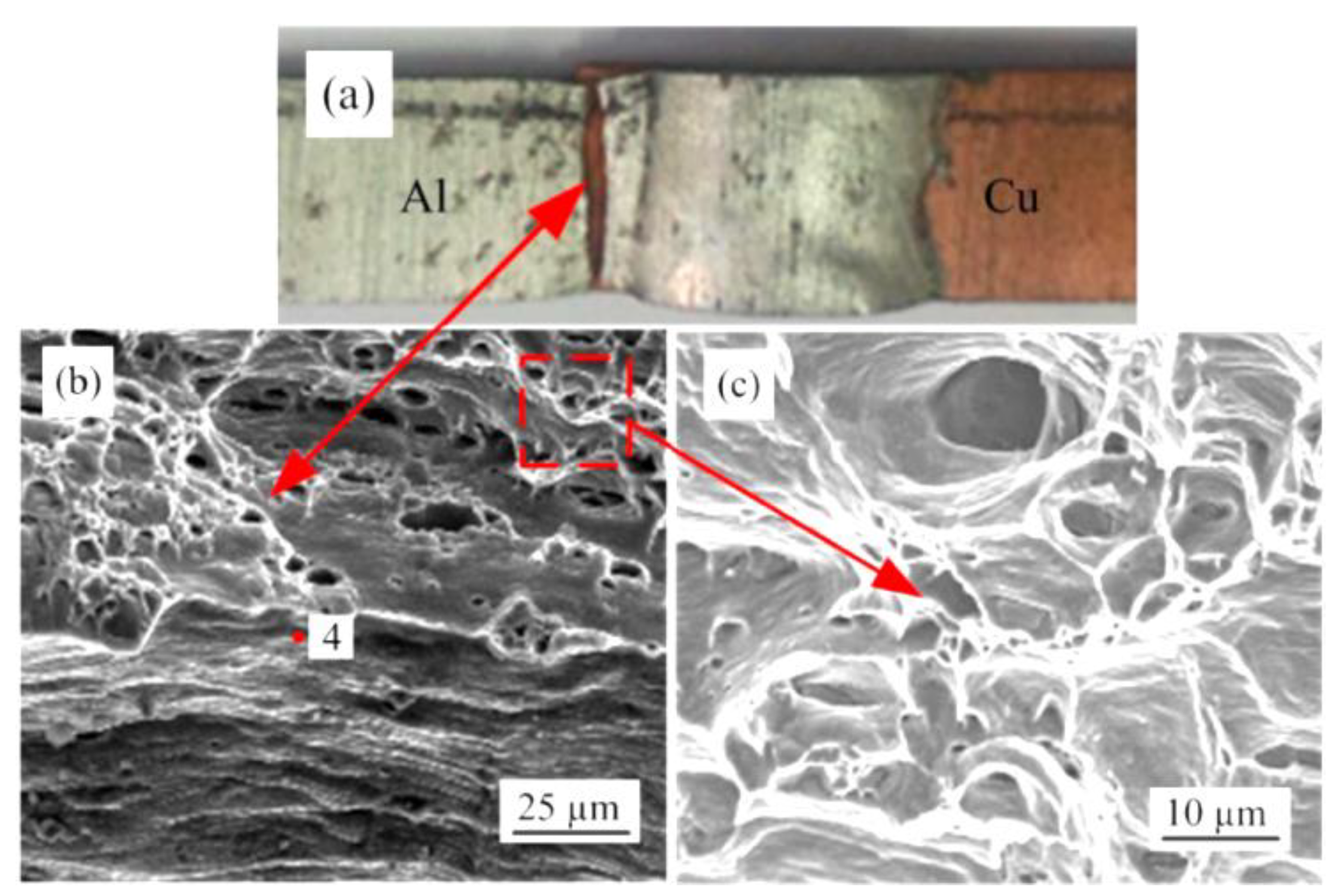
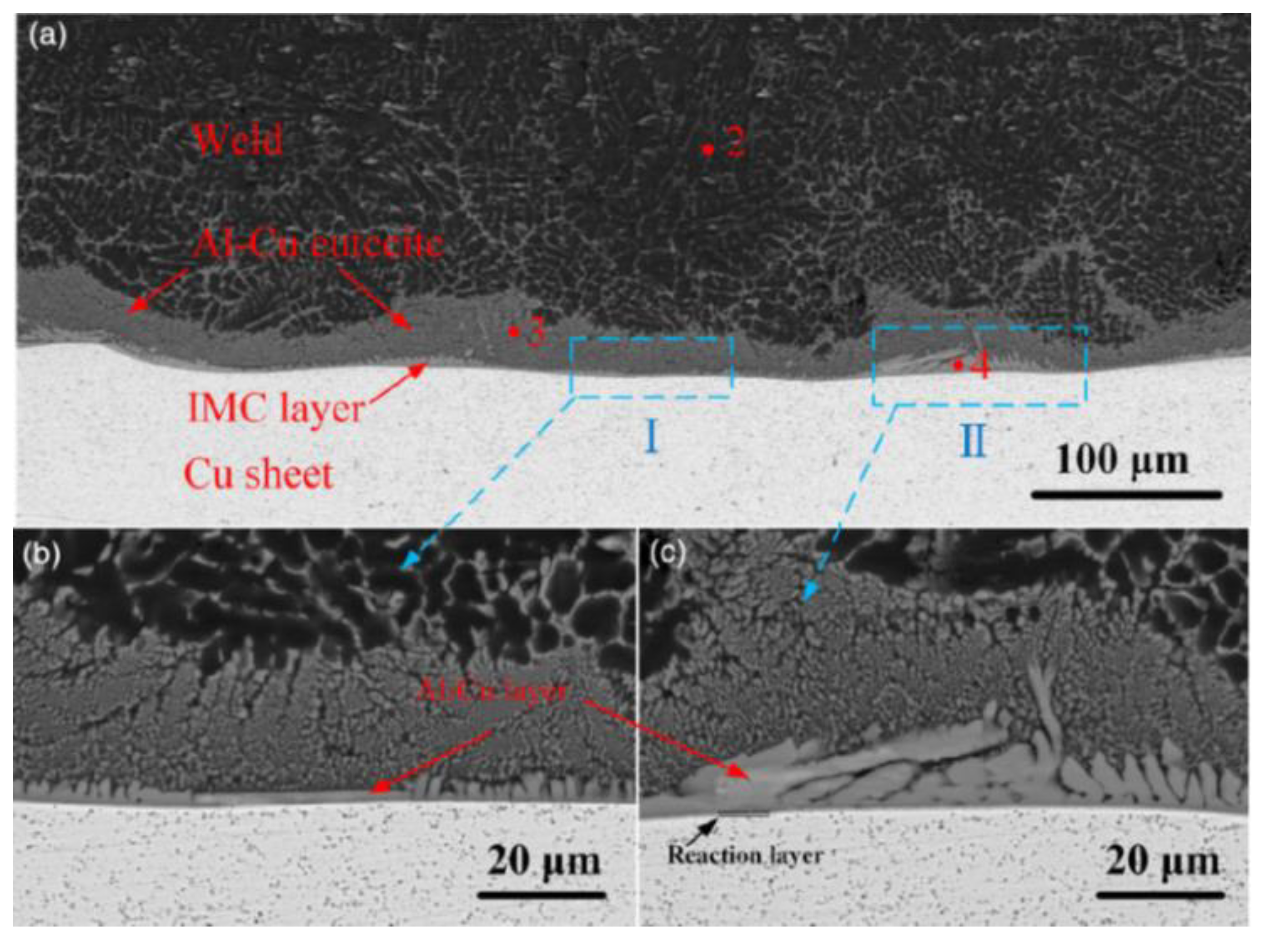
| GMAW-TIG Hybrid [73] | Cu & Al | 1. Heat input had direct relation with the strength of the joint. | 1. Eutectic Si particle caused the crack propagation |
| External magnet assisted CMT [74] | Cu & Al | 1. A copper–aluminum transition filler should be used. 2. The Al2Cu layer thickness evidently decreased under a high EMF. | 1. Brittle IMC formation. 2. A buttering layer of silver or silver alloy will help the welding of these materials using GMAW. |
| GMAW [75] | Cu & Ni | 1. The base metal and filler wire were properly mixed. 2. No serious problems arose when welding these two metals and their alloys. | 2. Any filler wire containing nickel and copper can be used for welding. |
| GMAW [76] & CMT [77] | Mg & Al | 1 The molten zinc compound prohibited the combination of the weld zone and the Mg base metal at the joint interface. 2. Zinc layer is used in the intermediate region of the weld plates. | 1. Brittle IMC and differences in melting points inhibit the welding. Precise control of the heat input is necessary. 2. A multilayered microstructure of eutectic structure, Mg17AL12, and Mg2Al3 layer forms in the fusion zone. |
| CMT [78] | Mg & Al | 1. Zinc-based Inconel 625 filler wire is used. | 1. Formation of Mg2Al3 had limitation on the strength of the joint. |
| TIG [79] | Co & Ni | 1. Performance of the joint was satisfactory under continuous high-temperature conditions, and it resisted oxidation and corrosion. 2. Heat input for welding cobalt should be kept at low-to-moderate level for better results. | 1. Not successfully achieved by conventional arc welding processes. 2. Good cobalt-welding practices require adequate joint preparation and thorough cleaning before welding to ensure sound joints. |
| Not welded by GMAW | Cu & Mg | - | Extremely difficult to join Mg alloys to Cu through GMAW. |
| Not welded by GMAW | Co & Cu; Co & Ni | - | Cracking can easily occur when welding cobalt and copper. |
| Metals | Al | Ni | Fe | Cu | Ti | Mg | Co |
|---|---|---|---|---|---|---|---|
| Al | - | W | W | W | W | W | N |
| Ni | W | - | W * | W | W | W | W |
| Fe | W | W * | - | W | W | W | W * |
| Cu | W | W | W | - | W | C | Cr |
| Ti | W | W | W | W | - | W | N |
| Mg | W | N | W | C | W | - | C |
| Co | C | N | W * | Cr | C | N | - |
| Hardness | Type of Grains | High Frequency—100 Hz | Low Frequency—5 Hz |
|---|---|---|---|
| High | Coarse | DC | DC |
| Intermediate | Intermediate coarse dendritic | AC, mixed | Mixed |
| Low | Fine dendritic | - | AC |
Publisher’s Note: MDPI stays neutral with regard to jurisdictional claims in published maps and institutional affiliations. |
© 2021 by the authors. Licensee MDPI, Basel, Switzerland. This article is an open access article distributed under the terms and conditions of the Creative Commons Attribution (CC BY) license (https://creativecommons.org/licenses/by/4.0/).
Share and Cite
Devaraj, J.; Ziout, A.; Abu Qudeiri, J.E. Dissimilar Non-Ferrous Metal Welding: An Insight on Experimental and Numerical Analysis. Metals 2021, 11, 1486. https://doi.org/10.3390/met11091486
Devaraj J, Ziout A, Abu Qudeiri JE. Dissimilar Non-Ferrous Metal Welding: An Insight on Experimental and Numerical Analysis. Metals. 2021; 11(9):1486. https://doi.org/10.3390/met11091486
Chicago/Turabian StyleDevaraj, Jeyaganesh, Aiman Ziout, and Jaber E. Abu Qudeiri. 2021. "Dissimilar Non-Ferrous Metal Welding: An Insight on Experimental and Numerical Analysis" Metals 11, no. 9: 1486. https://doi.org/10.3390/met11091486
APA StyleDevaraj, J., Ziout, A., & Abu Qudeiri, J. E. (2021). Dissimilar Non-Ferrous Metal Welding: An Insight on Experimental and Numerical Analysis. Metals, 11(9), 1486. https://doi.org/10.3390/met11091486