Article

Effect of Solidification Rates at Sand Casting on the Mechanical Joinability of a Cast Aluminium Alloy

Department of Mechanical Engineering, Paderborn University, Mersinweg 7, 33100 Paderborn, Germany
*
Author to whom correspondence should be addressed.
Metals 2021, 11(8), 1304; https://doi.org/10.3390/met11081304
Submission received: 30 June 2021 / Revised: 13 August 2021 / Accepted: 14 August 2021 / Published: 17 August 2021
(This article belongs to the Special Issue Casting and Rolling of Alloys)

Abstract

:
Implementing the concept of mixed construction in modern automotive engineering requires the joining of sheet metal or extruded profiles with cast components made from different materials. As weight reduction is desired, these cast components are usually made from high-strength aluminium alloys of the Al-Si (Mn, Mg) system, which have limited weldability. The mechanical joinability of the cast components depends on their ductility, which is influenced by the microstructure. High-strength cast aluminium alloys have relatively low ductility, which leads to cracking of the joints. This limits the range of applications for cast aluminium alloys. In this study, an aluminium alloy of the Al-Si system AlSi9 is used to investigate relationships between solidification conditions during the sand casting process, microstructure, mechanical properties, and joinability. The demonstrator is a stepped plate with a minimum thickness of 2.0 mm and a maximum thickness of 4.0 mm, whereas the thickness difference between neighbour steps amounts to 0.5 mm. During casting trials, the solidification rates for different plate steps were measured. The microscopic investigations reveal a correlation between solidification rates and microstructure parameters such as secondary dendrite arm spacing. Furthermore, mechanical properties and the mechanical joinability are investigated.

1. Introduction

Realisation of mixed construction concepts in modern automotive engineering requires the joining of sheet metal and extruded profiles with cast components made of different materials. The advantage of cast components for lightweight moulding is that the structure can be optimally adapted to the applied force and have good mechanical properties [1,2,3,4]. Furthermore, cast aluminium alloys are characterised by low melting temperature, good surface quality, castability, and low gas absorption, with the exception of hydrogen [5]. Since weight reduction is desired, these castings are usually made of high-strength aluminium alloys of the Al-Si (Mn, Mg) system. However, the weldability of cast aluminium alloys proves to be problematic [6]. The mechanical joinability of these components depends on their ductility, which is influenced by the microstructure [7,8]. Since high-strength cast aluminium alloys, such as AlSi10Mg or AlSi5Cu3Mg, have relatively low ductility, it is often not possible to produce a crack-free joint when using mechanical joining processes.
One of these mechanical joining processes is clinching, which is used in car body construction. Clinching is a joining process in which two or more layers of sheet metal or cast materials are joined, requiring no additional joining elements, such as those used in self-piercing riveting, and achieving a force-fitting and form-closed locking. The joint is created by cold forming of the joint partners by a punch and a die, creating an interlock [9,10,11].
One promising solution to prevent cracking during mechanical joining could be to grade the microstructure of the cast components in the intended joint areas [7,8]. This can be realized by local heat treatment or by adjusting the solidification conditions, both of which significantly increase ductility and thus improve the mechanical joinability of aluminium castings [12].
Cast aluminium alloys are divided into hypoeutectic, eutectic, and hypereutectic alloys; alloys of the Al-Si system are eutectic when they have a composition of 12.5 wt%Si. The chemical composition and the heat treatment influence both the mechanical and structural properties. The binary alloys of the Al-Si system are characterised by good castability, corrosion resistance, and mould filling, but also by slightly lower strengths. By specific modification of the eutectic, it is possible to improve the strength and ductility of a hypoeutectic Al-Si alloy. This is possible, for example, by refining with sodium and strontium. In addition, factors such as the solidification rate and the microstructure or the casting process also influence the characteristics of the mechanical properties [1,3,13,14,15]. The shape of the silicon solidifying in the (residual) eutectic affects the ductility of the castings. The coarse Al-Si needles or platelets are shown in Figure 1A; they greatly reduce ductility [16]. Refining the cast structure by adding trace elements, such as strontium (see Figure 1B), leads to an improvement in the morphology of the Si particles [17]. In AlSi cast alloys, the refinement results in a very fine-grained, partially fibrous formation of the silicon crystals in the solidified eutectic, which increases the ductility by up to three times. Furthermore, the modification remains intact, even when the alloys are remelted. Refining is usually only carried out with a silicon content of 7–13% [2,4,14,18]. An improvement of the morphology can also be achieved by a higher solidification rate or by a subsequent homogenization annealing (see Figure 1C), in accordance with Neuser et al. [17]. For the latter, it is important to note that the distance between the secondary dendrite arm is smaller than 50 µm [2]. In the study by Zhao et al. [7], a W3 cast aluminium alloy of the company Ryobi was used on the die side, which was joined with self-pierce riveting (SPR). It was shown that the heat treatment changes the morphology of the eutectic silicon and the joinability for this alloy could be improved, but with a reduction of the mechanical performance [7,19].
In sand casting, a distinction is made between lost foam and permanent pattern casting. While there are also processes in which a lost pattern is used, they are not considered further here. The sand casting process is suitable for all aluminium alloys, including alloys that are prone to hot shortness [20]. Greensand or dry sand is used as the moulding material, the latter requiring a binder system to create a solid mould. The moulding material serves not only to create a solid mould for the cast material that can withstand the high casting temperatures without damage but also to prevent pores in the subsequent casting due to its high permeability to air and casting gases. The sand casting process allows a component thickness of 4.0 mm, although wall thicknesses with a minimum of 2.0 mm can also be cast. Compared to other casting processes, the strength is lower due to the lower solidification speed. It is possible to improve the mechanical properties by the choice of sand, as the heat capacity can be increased, which in turn increases the solidification rate [3,20,21].
The procedure for sand casting is the same, regardless of whether green sand or dry sand is used. The casting pattern and the sprue system pattern are placed in so-called mould boxes, which are usually made of metal or wood. Then, the casting box is filled with the moulding material and compacted by hand or with a pneumatic tamper. Finally, the models are removed, and the resulting carvings can be cast [3,14].
This study aims to establish relationships between solidification conditions in sand casting, microstructure parameters, mechanical properties, and joinability to prevent cracks in the closing head during clinching.

2. Materials and Methods

2.1. Charge Materials
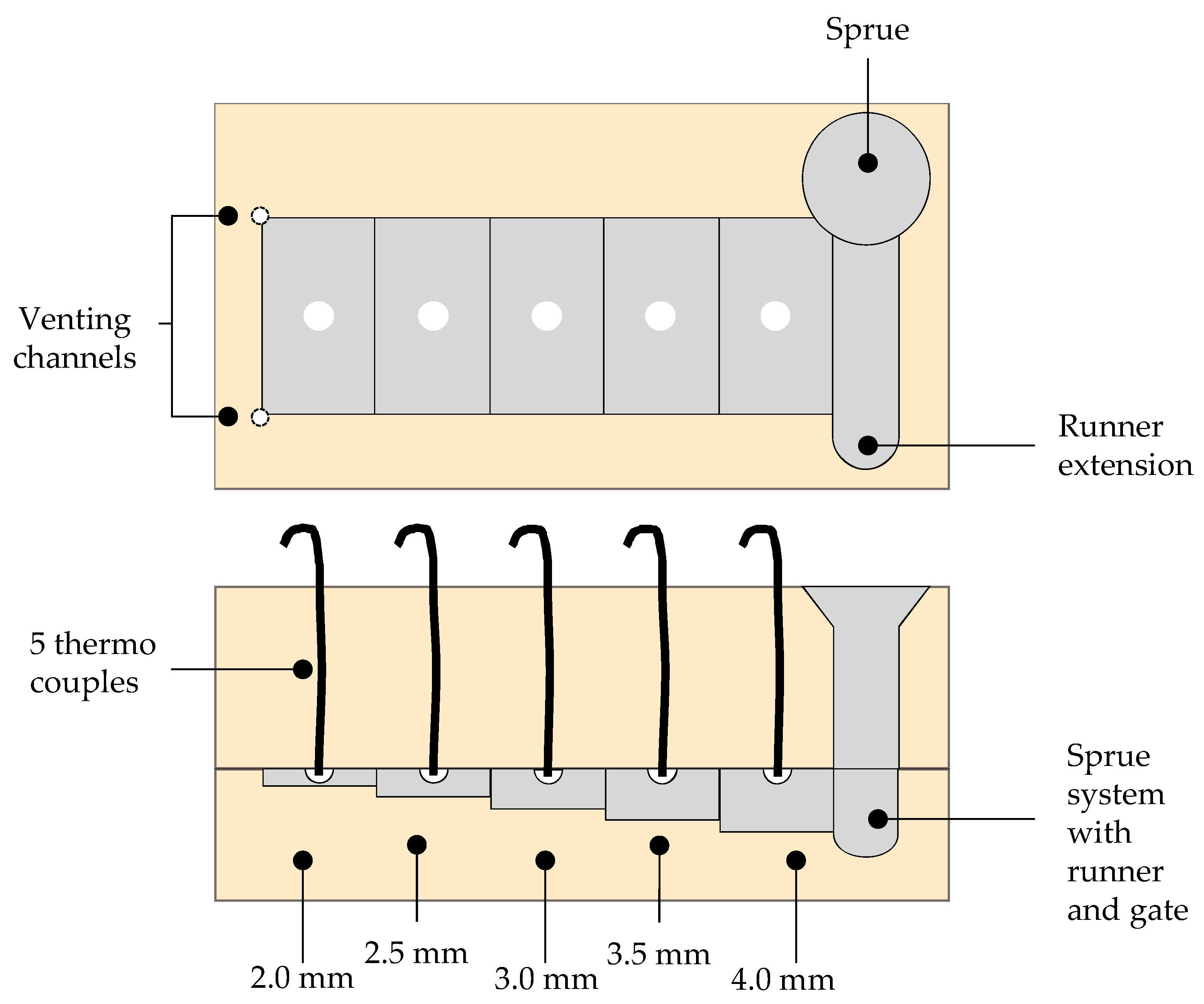
For this study, the hypoeutectic cast alloy AlSi9, which is suitable for casting due to the high silicon content, is used. The alloy is available in ingots and is melted for the respective tests. Moreover, the AlSi9 is a pre-refined cast aluminium alloy that shows a microstructure as shown in Figure 1B in the as-cast state. Since AlSi9 cannot be heat treated, the samples were used in the as-cast condition.
The alloy used is in refined condition and was produced by the company Trimet Aluminium SE, from which AlSi9 also originated. Trimet uses the name Trimal 37 as the trade name [22].
Furthermore, the dual-phase steel HCT590X is used in this study. The steel sheet serves as joining material for the clinching process shown later, whereby the steel is used on the die and punch side.

2.2. Sand Casting

A step plate was used as the metal model, which consisted of a total of five steps. The minimum thickness was 2.0 mm and increased by 0.5 mm per step to a final thickness of 4.0 mm. This model had a length of 200.0 mm and a width of 80.0 mm. This means that each stage was 40.0 mm × 80.0 mm, from which the specimens for the microscopic and mechanical investigations were taken.
Plates with a consistent thickness measuring 240.0 mm × 120.0 mm were cast for the joining investigation. From these plates, sections with the dimensions 45.0 mm × 45.0 mm were cut, which were used in accordance with the DVS guideline [10] for clinch testing.

2.3. Melting

Melting was carried out in a resistance furnace, in which the melt was superheated to a temperature of 720 °C. The ingots were melted in a graphite crucible and poured off immediately after reaching the melting temperature.

2.4. Chemical Composition

To interpret the results of the microstructure analysis and to evaluate the mechanical properties of the components selected for joining, it is necessary to know the exact chemical composition of the materials used in the investigations. The chemical compositions of the AlSi9 alloy and the steel sheet were determined using the Bruker model Q4 TASMAN optical emission spectroscope.

2.5. Solidification Rate Measurements
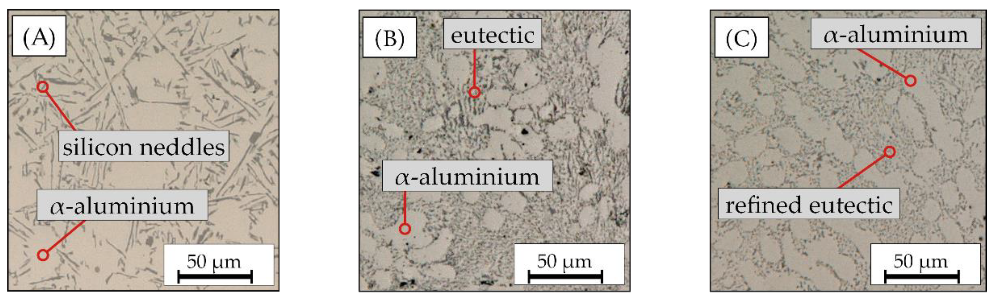
The individual solidification rates were determined by means of the before mentioned step plate, with temperatures recorded for each step (2–4 mm). The experimental setup is shown in Figure 2. The individual temperatures were measured with K-type thermocouples connected to the Ganter Q.brixx XL A107 amplifier (Gantner instruments, Rodgau, Germany) and subsequently recorded using the Gartner GI.bench software at a recording frequency of 50 Hz.

2.6. Metallography

The specimens for the light microscopy (LOM) and DAS measurement were embedded with the two-component embedding resin CEM1000 blue of the company Cloeren Technology. The mixing ratio was 1 powder to 0.8 resin. Subsequently, the specimens were gradually polished to a grit size of 4000 and then further polished on an automatic polishing machine for 18 h with a suspension containing abrasive particles with a size of 0.50 µm. The silica suspension of the company Cloeren Technology has a pH-value of 9–9.5, so that the specimen surface is also slightly etched during the polishing process. The samples for the Brinell hardness test were only sanded to a grain size of 4000, but not polished. The LOM images and the measurement of the DAS were taken with the Keyence VHX5000 digital microscope.

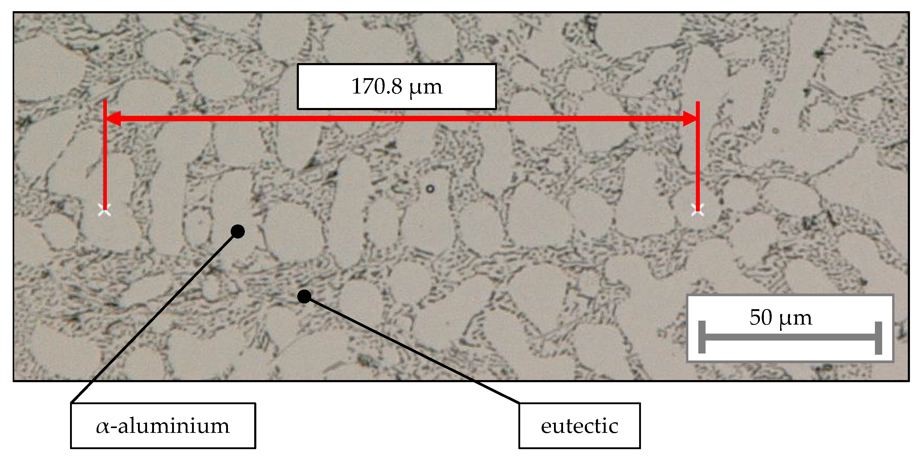
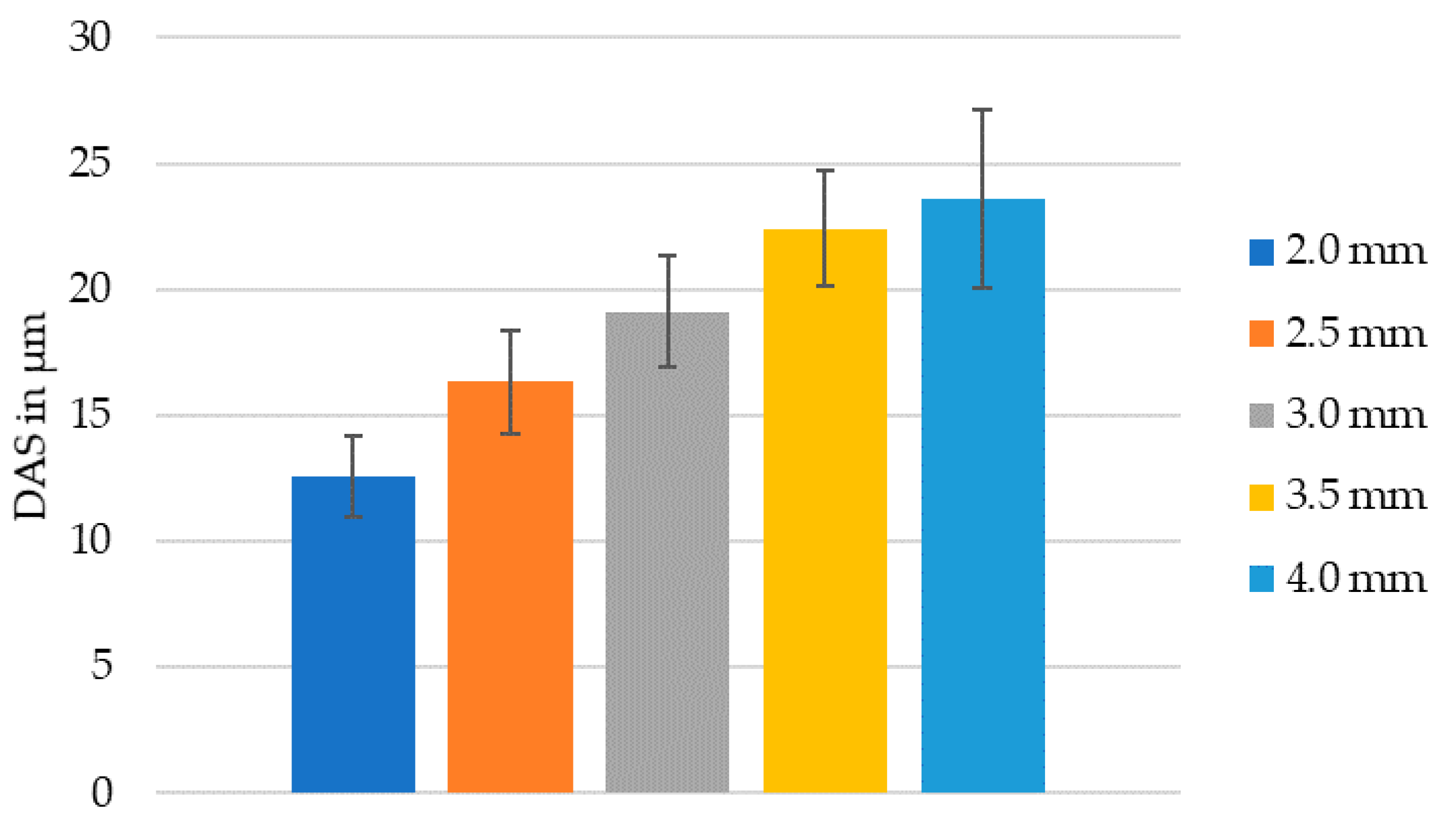
2.7. Secondary Dendrite Arm Spacing

The secondary dendrite arm spacing (DAS) was measured according to BDG-guideline P220 [23]. Therefore the specimens were taken from every step out of the middle of the plate. To measure DAS, the cross-sectional area was investigated. The LOM-images were taken by a magnification of 300. A minimum of 10 dendrite arms were taken into account for each step of the stepped plate to determine the DAS, using Equation (1).
DAS = x ( m 1 )
where
  • x = length of the dendrite stem and
  • m = number of dendrites.
The evaluation of the DAS includes the average length of the dendrite arm spacing and the associated standard deviation.

2.8. Mechanical Tests

The mechanical tests included tensile tests as well as measurements of the Brinell hardness. Both tests are briefly explained below.

2.8.1. Tensile Tests

The tensile tests were performed with the universal testing machine MTS 858 Table Top System. A minature specimen geometry was chosen according to DIN EN ISO 6892-1. The measuring range of the flat tensile specimen was 5.0 mm long with a radius of 2.0 mm to the clamping areas. The test rate was 1.5 mm/min with a clamping pressure of 7 MPa. For every step, nine specimens were tested.

2.8.2. Hardness Tests
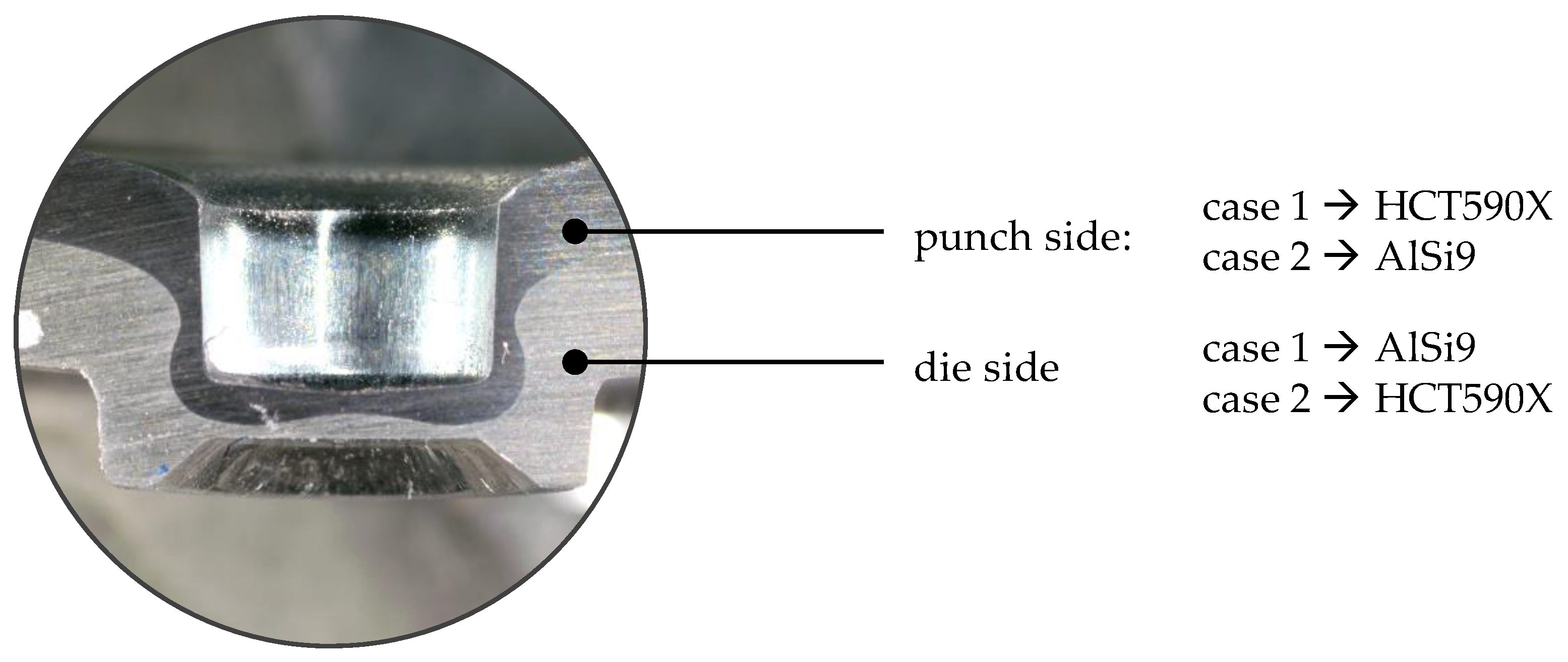
The Brinell hardness according to DIN EN ISO 6506-1 was measured with the Frankoskop hardness testing machine from Franke. A ball with a diameter of 2.5 mm was used. The samples were loaded with a force of 62.5 kp (612.9 N) with a loading time of 10 to 15 s. The surface was prepared with a grinding wheel with a grit size of 4000. A total of five hardness indentations were made for every cast step.

2.9. Clinching

Single-stage clinching with a rigid die was used for the joints shown in this study. The TOX MC 4.2 clinching machine was used for the joining process.
Afterwards, limit values that a clinch joint must have in order to be labelled as sustainable were defined. Table 1 shows these limit values for the different parameters.
Specimens with a size of 45.0 mm × 45.0 mm were used to investigate the clinch points. Dual-phase steel HCT590X and the cast AlSi9 plates with thicknesses of 2.0 and 3.0 mm were selected for both the punch and die side (see Figure 3). In this figure, the two joining directions are marked, depending on the direction, different punches and dies were used for the clinch specimens:
Case 1: punch type A48100 and die type BD8016.
Case 2: punch type A48105 and die type BD8008.
The punch types used differ in the edge radius. It accounts for 0.2 mm in stamp type A48100, whereas the edge radius of stamp type A48105 is larger at 0.5 mm. Especially when the more brittle aluminium casting is used on the punch side, it is advantageous to use a punch that exerts less force in the forming area at the interlock due to the larger edge radius.

3. Results and Discussion

3.1. Chemical Composition

The chemical compositions of the AlSi9 alloy and the dual-phase steel HCT590X are shown in Table 2.
The strength and ductility of the Al-Si alloys are affected by the properties of the Si structure. If the silicon crystal structure in the eutectic is minimized by refinement, the mechanical properties also increase [20]. Permanent refinement with strontium causes a finer formation of the eutectic and leads to an increase in ductility [3,22]. The strontium content of 0.048% is particularly important. According to the publication by Duygun et al. [16], this measured proportion is suitable for the refinement of AlSi alloys.
The high silicon content of the cast aluminium alloy is a challenge during large deformation, as silicon reduces the elongation at fracture due to its brittle and acicular character [20]. However, high ductility is important for deformation at the closing head [7]. Furthermore, Zhao et al. [7] showed that the eutectic silicon causes cracks during deformation. Although the cast aluminium alloy used in the study was already long-term refined with strontium and thus improved from the outset, another strategy was required because there were still cracks in the closing head. One strategy is the heat treatment of the cast alloy which can make the refined eutectic silicon even rounder. This increases the elongation at fracture and can also prevent cracks in the closing head.

3.2. Secondary Dendrite Arm Spacing

An example of the measurement and evaluation of the DAS is the LOM image in Figure 4, where a 170 µm long dendrite stem can be seen. As shown in Equation (1), the length of a dendrite arm stem is divided by the number of individual dendrites, thus determining the DAS for a dendrite stem.
Furthermore, the α-aluminium and the fine eutectic silicon achieved by refining with 0.048% strontium are visible. The results of the DAS measurements are shown in Figure 5.
At the smallest step thickness of 2.0 mm, the smallest DAS was measured with an average distance spacing of 10 µm. The thicker the respective plate steps were, the longer the respective distances were. The mean measured DAS increased by about 3 µm each between a plate thickness of 2.0 and 3.5 mm. In comparison, the mean DAS difference was 1.1 µm only between a plate thickness of 3.5 and 4.0 mm. It can be assumed that these steps take longer to fill due to their thickness and therefore solidify much later than the thinner steps. The thinner the casting, the faster it solidifies, and accordingly, the thicker the casting, the greater the DAS (see also Supplementary Materials). Furthermore, the DAS are directly related to the mechanical properties of a cast component. The smaller the DAS, the better the mechanical properties. The reason for this is the finer and thus faster solidified structure of the casting.

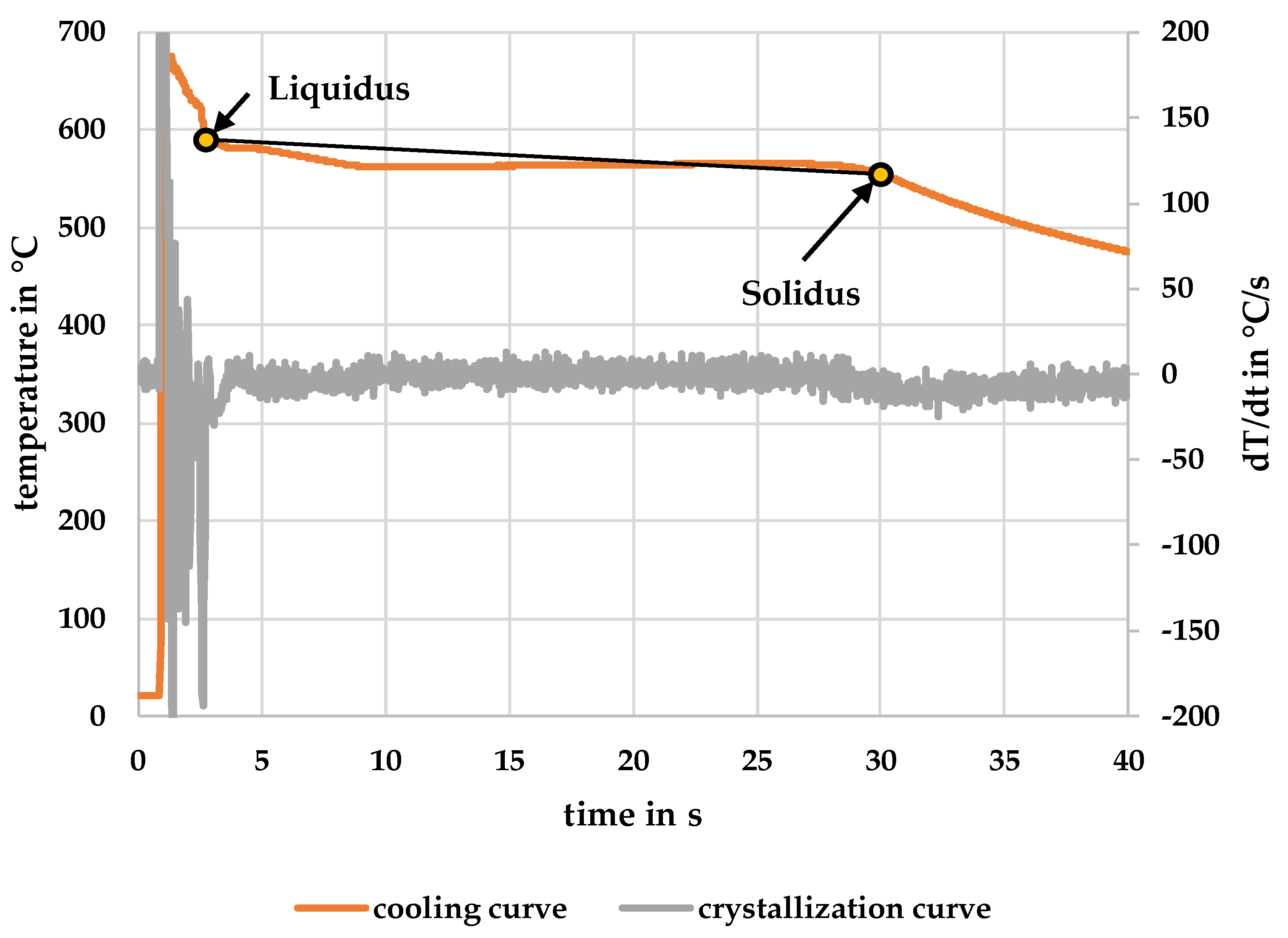
3.3. Solidification Curve and Cooling Rate

The solidification curves were determined for all plate thicknesses, as shown in Figure 3. The temperatures were always recorded in the centre of a step. Figure 6 shows exemplarily the recording of a complete solidification curve. For all stepped plate thicknesses the solidification curves were measured. Based on Equation (2), the solidification rate (SR) for the individual plate stages was calculated in accordance with Vandersluis and Ravindran [24]. Equation (2) represents the quotient of the temperature and time of the delta from solidus to liquidus. Figure 6 shows an example of the solidification curve for a 4 mm thick plate.
SR = T Solidus Liquidus t Solidus Liquidus
The grey curve in Figure 6 corresponds to the first derivation of the solidification curve according to the cooling curve analysis method (CCA method) [25]. Due to this method, the liquidus and solidus temperatures were determined and afterwards the solidification rates were calculated.
The solidification curve in Figure 6 and the measured DAS in Figure 5 show that the faster a plate stage solidifies, the smaller the DAS. This is due to the fact that more solidification nuclei are formed when the melt is undercooled faster. The solidification rates for the 2.0 to 4.0 mm steps are shown in Table 3. In Table 3 and Figure 5 it can be seen that not only the solidification rates of the 3.0 to 4.0 mm thick steps are very close to each other, as already mentioned, this also applies to the measured DAS of exactly these steps. This supports the assumption that these steps solidify lastly. Furthermore, the difference in the solidification rate to the 2.0 and 2.5 mm stages is large with 3.8 and 3.4 °C/s, respectively.

3.4. Mechanical Properties

The measured mechanical properties can be found in Table 4. The strength properties of AlSi9 correlate with the solidification rates and the measured DAS, i.e., the lower the DAS and the solidification rate, the higher the strength of the cast alloy. A characteristic feature of cast components is the so-called staircase curve, which describes the decreasing mechanical properties with increasing thickness of the cast component, which is directly related to the DAS because higher solidification rates lead to significantly lower DAS.
An increase in the solidification rate from 1.4 °C/s for a step thickness of 4.0 mm to 3.8 °C/s for a step thickness of 2.0 mm led to an increase in the tensile strength of 10% and an increase in the yield strength of 11%. The Brinell hardness also experienced an increase, but with a value of 5%.
For further analysis, the yield strength ratio was determined as the quotient of the yield strength and the tensile strength. Based on the literature source [10], this ratio should be below 0.70 in order to ensure a proper clinch joint. Based on the mechanical properties determined here, the elasticity ratio of 0.40 to 0.43 indicates that the aluminium casting alloy AlSi9 is suitable for clinching. Furthermore, the tensile strength should be below a limit value of 500 MPa, which is also achieved with a value of 197 to 178 MPa. The variation of the elongation at fracture is striking. It is lowest at 2.0 mm, while it is highest at 3.0 mm with 14%. A reason for this is the somewhat higher porosity (0.047%) of the 2.0 mm thick castings compared to 0.015% for the 3.0 mm thick castings.

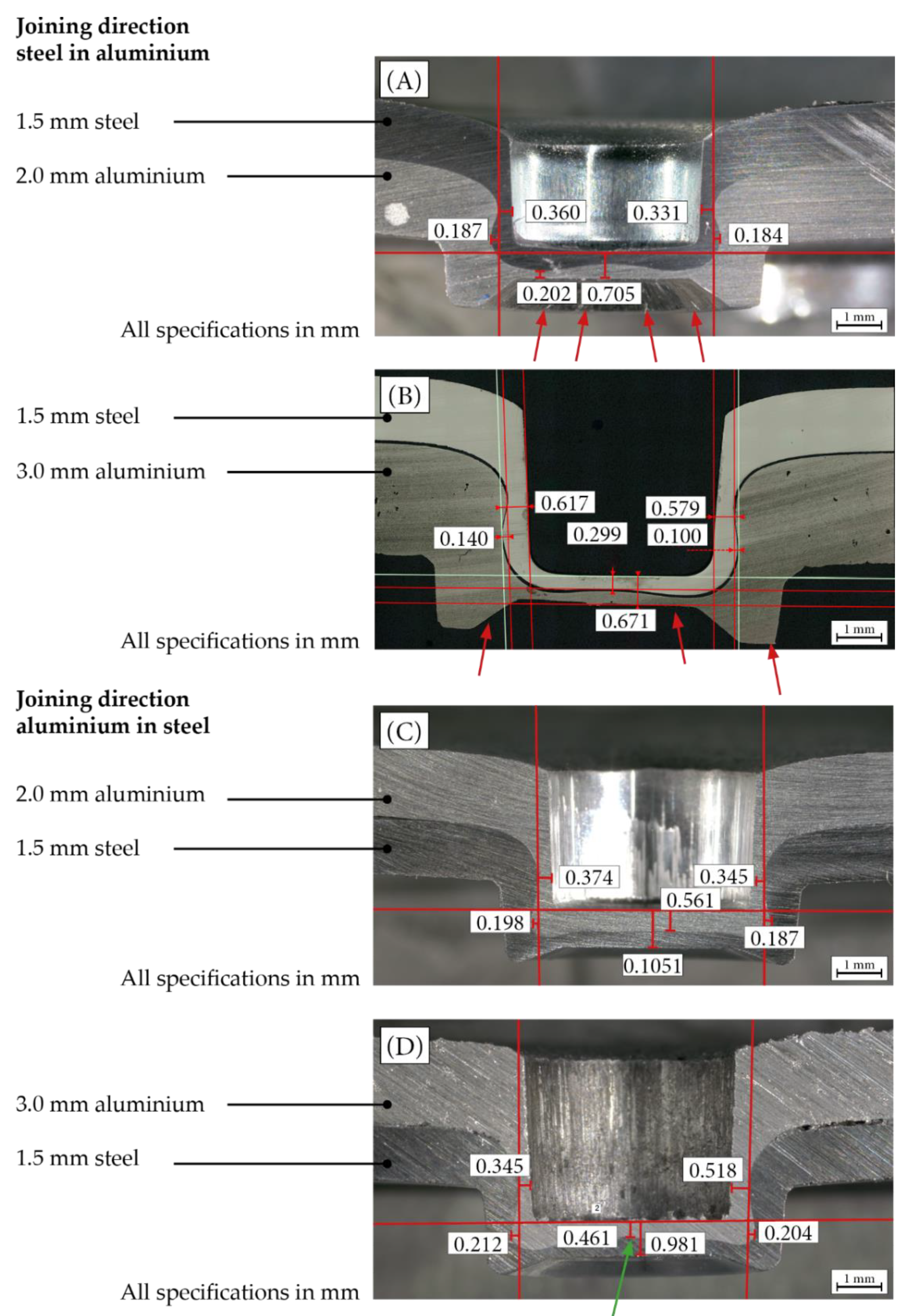
3.5. Microsection of Clinching Joint

Within the scope of the joining investigation, aluminium plates were joined with different joining directions in each case, whereby joints with 2.0 and 3.0 mm thick aluminium plate steps served as examples. Normally, “hard” to “soft” is selected as the joining direction for a clinch joint and represents the more critical value in this study, which can be seen in the left column of Figure 7. Meanwhile, in the right column of Figure 7, the joining direction of cast aluminium in steel can be seen, which corresponds to the “thick” in “thin” approach.
Figure 7A shows an example of a cross-section of a clinch specimen. The steel sheet HCT590X with a thickness of 1.5 mm is used on the punch side and AlSi9 with a thickness of 2.0 mm is used on the die side. Based on Table 1, it is possible to evaluate this cross-section using the limit values listed. The interlock, which is particularly important for the strength of a clinch joint, always exceeds the minimum limit values in the present case. While no cracks are visible in the aluminium casting at the boundary line, they are visible on the outside of the locking head, here marked with red arrows. The greatest deformations occur here as well as at the interlock. Therefore, high elongation at fracture of at least 12% is required to prevent cracking [10]. Figure 7B shows a clinch joint using a 3.0 mm thick aluminium casting on the die side. Comparing the limit values listed in Table 1, it can be seen that the interlock of such a joint does not conform to the requirements. The following problem arises: Due to the insufficient interlock, a perfect load-bearing capacity of the joint cannot be guaranteed during shear loading or head tension. Accordingly, the joint unbolts too quickly under load. Although other die and punch combinations were used to counteract this issue, the joint shown here represents the best result for the 3 mm thick aluminium casting. For example, a punch with a smaller edge radius was used in an attempt to create more interlock due to the resulting higher material flow, but this displaced too much material in the neck area of the joint. The result is a neck fracture which means a complete failure of the joint. Moreover, there are also cracks in the closing head of the 3.0 mm thick aluminium casting.
A comparison of solidification rates in Table 3 and the mechanical characteristics in Table 4 shows that the 2.0 mm thick aluminium casting represents a threshold value for the strength. The solidification rate is so high that correspondingly smaller DAS results lead to better mechanical characteristics. The slightly higher Brinell hardness, tensile strength, and yield strength mean that the material offers more resistance during the joining process and it is easier to form an interlock with the punch. However, it is noticeable that more cracks occur in the closing head of the 2.0 mm castings than in the 3.0 mm castings. The elongation at fracture is slightly lower in 2.0 mm castings, which leads to formation of cracks in the closing head as a result of the joining process.
Figure 7C shows a clinched joint where the joining direction of the cast aluminium (punch side) in sheet steel (die side) was selected. Compared to the characteristic values from Table 1, it is evident that all limit values are complied with and that this is also a load-bearing joint. Furthermore, no cracks are visible in the aluminium casting on the punch side as well as in the junction to the steel sheet. The clinch joint in Figure 7D, which uses the 3.0 mm thick aluminium casting on the punch side, also represents a load-bearing joint according to the criteria of Table 1. The stronger bulge in the middle of the closing head, marked here with a green arrow, is remarkable. Although the bottom thickness of 0.461 mm is clearly above the limit value of 0.2 mm from Figure 1, it can be seen that due to the lower solidification rate and the associated lower mechanical properties of the aluminium casting with a 3.0 mm thickness, the resistance as a result of the joining process is lower, which results in the bulge marked here. Especially with thicker aluminium castings, this bulging can be even more significant and can lead to early failure under certain load directions, mainly in the transverse direction.
In a brief conclusion, no cracks can be detected in the clinch joints with the joining direction of cast aluminium in steel.
AlSi9 is already more ductile due to the refinement with strontium, since the eutectic silicon, as can already be seen in Figure 1B, is no longer acicular or plate-shaped but significantly finer. In order to further increase the ductility, further investigations will aim to heat treat the naturally hard AlSi9. In this way, the eutectic silicon can be made much rounder and even more finely grained than in Figure 1C [26], which increases ductility [3,8]. This procedure will be especially helpful for the joining direction steel in aluminium casting, as the higher ductility in the area of the closing head will lead to less crack induction.

4. Conclusions

In this study, the relationship between the microstructure and the associated joinability was investigated. For this purpose, plates with a thickness of 2.0 to 4.0 mm were cast using the sand casting process. Samples were taken from these for mechanical testing and micrographs were taken, from which the dendrite arm spacing (DAS) was measured. In addition, further plates with a thickness of 2.0 and 3.0 mm were produced, which were subsequently joined with the steel sheet HCT590X by means of clinching. These were used to sample the joint. The tests showed the following relationship: the faster the associated solidification rate, the smaller the determined DAS and the higher the measured mechanical properties. The changed solidification speed is followed in this investigation by the different thicknesses of the cast components. That is, a smaller thickness leads to faster solidification and smaller DAS. Similarly, a comparable thickness of 4 mm leads to slower solidification and correspondingly larger DAS. A suitable joinability results from the short DAS of the 2.0 mm thick casting.
The joining direction steel in aluminium with a thickness of 2.0 mm represents a threshold value for a suitable joint because with a thickness of 3.0 mm no joint could be made according to the DVS guideline. This applies in particular to the interlock of the clinched joint. Other major findings of the study are listed below:
AlSi9 can be cast as a step plate with a minimum thickness of 2.0 mm.
Due to the refinement of AlSi9, higher deformations are possible during the joining process, which allows for defect-free joints. Future investigations will aim at specific heat treatment of the AlSi9 to further increase the joinability.
A solidification rate of 3.8 °C/s and a DAS of 13 µm and were achieved at a thickness of 2.0 mm. However, the solidification rate of 3.8 °C/s is the limit value for obtaining a joint that meets the criteria mentioned by a joining direction from steel in aluminium. No cracks were found in the reverse joining direction.
The solidification rates of 2 °C/s during sand casting of thin elements with a thickness below 3.0 mm and a measured DAS of 19 µm are sufficient to obtain a fine dendritic microstructure in AlSi-alloys, which enables the production of crack-free clinch joints by the joining direction of aluminium in steel. At the reverse joining direction, occasional cracks could be detected. Moreover, the DVS guideline could not be complied with at the limit values shown.

Supplementary Materials

The following are available online at https://www.mdpi.com/article/10.3390/met11081304/s1, Figure S1: LOM-image of AlSi9 with a thickness of 2.0 mm. Figure S2: LOM-image of AlSi9 with a thickness of 2.5 mm. Figure S3: LOM-image of AlSi9 with a thickness of 3.0 mm. Figure S4: LOM-image of AlSi9 with a thickness of 3.5 mm. Figure S5: LOM-image of AlSi9 with a thickness of 4.0 mm.

Author Contributions

Conceptualization, M.N. and O.G.; methodology, M.N. and O.G.; validation, M.N. and A.A.; formal analysis, M.N.; investigation, M.N.; writing—original draft preparation, M.N.; writing—review and editing, O.G. and A.A.; visualization, M.N.; supervision, O.G. and M.S.; project administration, M.S.; funding acquisition, M.S. All authors have read and agreed to the published version of the manuscript.

Funding

This research was funded by the Deutsche Forschungsgemeinschaft (DFG, German Research Foundation)—TRR 285—Project-ID 418701707.

Acknowledgments

The authors thank the German Research Foundation for their organizational and financial support. Furthermore, the authors would like to take this opportunity to thank Yaroslav Frolov, the Head of the Metal Forming Department of the National Metallurgical Academy of Ukraine in Dnipro, and Jan Tobias Krüger, at the Paderborn University, Moritz Klöckner, as well as Jonathan Hartmann for their support in preparation and conducting of the casting trials.

Conflicts of Interest

The authors declare no conflict of interest.

References

  1. Mallick, P.K. Materials, Design and Manufacturing for Lightweight Vehicles; CRC Press: Boca Raton, FL, USA, 2011; ISBN 1613443641. [Google Scholar]
  2. Ostermann, F. Anwendungstechnologie Aluminium; Springer: Berlin/Heidelberg, Germany, 2014; ISBN 978-3-662-43806-0. [Google Scholar]
  3. Kaufman, J.G.; Rooy, E.L. Aluminum Alloy Castings: Properties, Processes, and Applications; ASM International: Materials Park, OH, USA, 2004; ISBN 1615030476. [Google Scholar]
  4. Gruzleski, J.E.; Closset, B.M. The Treatment of Liquid Aluminium-Silicon Alloys; American Foundrymen’s Society, Inc.: Des Plaines, IL, USA, 1999; ISBN 978-0874331219. [Google Scholar]
  5. Polmear, I.; St. John, D.; Ne, J.; Qian, M. Light Alloys: From Traditional Alloys to Nanocrystals, 5th ed.; Elsevier Science & Technology: Oxford, UK, 2017; ISBN 008099430X. [Google Scholar]
  6. Machuta, J.; Nová, I.; Kejzlar, P. Structure and Mechanical Properties of Aluminium Alloys AlSi10 and AlSi5Mg. Manuf. Technol. 2017, 17, 772–777. [Google Scholar] [CrossRef]
  7. Zhao, X.; Meng, D.; Zhang, J.; Han, Q. The effect of heat treatment on die casting aluminum to apply self-pierce riveting. Int. J. Adv. Manuf. Technol. 2020, 109, 2409–2419. [Google Scholar] [CrossRef]
  8. Zhang, D.; Zheng, L.; StJohn, D. Effect of a short solution treatment time on microstructure and mechanical properties of modified Al–7wt.%Si–0.3wt.%Mg alloy. J. Light Met. 2002, 2, 27–36. [Google Scholar] [CrossRef]
  9. Echempati, R. Primer on Automotive Lightweighting Technologies, 1st ed.; CRC Press: Boca Raton, FL, USA, 2021; ISBN 9780815357131. [Google Scholar]
  10. DVS/EFB. Merkblatt Clinchen; DVS Media GmbH: Düsseldorf, Germany, 2002. [Google Scholar]
  11. Mucha, J. Clinching technology in the automotive industry. Arch. Automot. Eng. 2017, 76. [Google Scholar] [CrossRef]
  12. Di Michele, G.; Guglielmi, P.; Palumbo, G.; Sorgente, D. Investigation on the Strain Behaviour of a Precipitation-Hardenable Aluminium Alloy through a Temperature Gradient Based Heat Treatment. KEM 2015, 639, 361–368. [Google Scholar] [CrossRef]
  13. Hatch, J.E. Aluminum: Properties and Physical Metallurgy; American Society for Metals: Metals Park, OH, USA, 1984; ISBN 1615031693. [Google Scholar]
  14. Fredriksson, H.; Åkerlind, U. Materials Processing during Casting; Wiley: Chichester, UK; Hoboken, NJ, USA, 2010; ISBN 0470015144. [Google Scholar]
  15. Warmuzek, M. Aluminum-Silicon Casting Alloys: Atlas of Microfractographs; ASM International: Materials Park, OH, USA, 2004; ISBN 0871707942. [Google Scholar]
  16. Duygun, İ.K.; Hapçı Ağaoğlu, G.; Dispinar, D.; Orhan, G. Time-dependent corrosion properties of Sr-modified AlSi9 alloy analyzed by electrochemical techniques. J. Alloys Compd. 2019, 803, 786–794. [Google Scholar] [CrossRef]
  17. Neuser, M.; Kappe, F.; Busch, M.; Grydin, O.; Bobbert, M.; Schaper, M.; Meschut, G.; Hausotte, T. Joining suitability of cast aluminium for self-piercing riveting. IOP Conf. Ser. Mater. Sci. Eng. 2021, 1157, 12005. [Google Scholar] [CrossRef]
  18. Zolotorevskiĭ, V.S.; Belov, N.A.; Glazoff, M.V.; Zolotorevski, V.; Belov, N.A. Casting Aluminum Alloys, 1st ed.; Elsevier: Oxford, UK, 2007; ISBN 9780080453705. [Google Scholar]
  19. Zhao, X.; Zhang, J.; Chu, Y.; Cheng, P.; Meng, D. Research on Joining High Pressure Die Casting Parts by Self-Pierce Riveting (SPR) Using Ring-Groove Die Comparing to Heat Treatment Method. In SAE Technical Paper Series; WCX SAE World Congress Experience, 21 April 2020; SAE International: Warrendale, PA, USA, 2020. [Google Scholar]
  20. Lumley, R.N. Fundamentals of Aluminium Metallurgy: Production, Processing and Applications; Woodhead Publishing: Cambridge, MA, USA, 2018; ISBN 978-0-08-102063-0. [Google Scholar]
  21. Glazoff, M.V. Casting Aluminum Alloys, 2nd ed.; Butterworth-Heinemann: Oxford, UK, 2019; ISBN 978-0-12-811805-4. [Google Scholar]
  22. Trimet Aluminium SE. Trimal-37: Druckgusslegierung für Duktile Anwendungen. Available online: https://www.trimet.eu/de/trimal_produktblaetter_pdf/produktblatt-trimal-37-asi-2020.pdf (accessed on 16 August 2021).
  23. BDG-Bundesverband der Deutschen Gießerei-Industrie. P220-Bestimmung des Dendritenarmabstandes für Gussstücke aus Aluminium-Gusslegierungen; Verein Deutscher Giessereifachleute e. V. (VDG): Düsseldorf, Germany, 2011. [Google Scholar]
  24. Vandersluis, E.; Ravindran, C. Influence of solidification rate on the microstructure, mechanical properties, and thermal conductivity of cast A319 Al alloy. J. Mater. Sci. 2019, 54, 4325–4339. [Google Scholar] [CrossRef]
  25. Emadi, D.; Whiting, L.V.; Nafisi, S.; Ghomashchi, R. Applications of thermal analysis in quality control of solidification processes. J. Therm. Anal. Calorim. 2005, 81, 235–242. [Google Scholar] [CrossRef]
  26. Haque, M.; Maleque, M. Effect of process variables on structure and properties of aluminium–silicon piston alloy. J. Mater. Process. Technol. 1998, 77, 122–128. [Google Scholar] [CrossRef]
Figure 1. Al-Si casting alloy system; (A) non-refined; (B) refined; (C) homogenisation annealed by 380 °C and 4 h, authors own figure. Represents an extension to the figure in Neuser et al. [17].
Metals 11 01304 g001
Figure 2. Experimental setup with the measurement of solidification curves.
Metals 11 01304 g002
Figure 3. Joining direction for clinching, separated in two cases.
Metals 11 01304 g003
Figure 4. LOM image of AlSi9 refined with 0.048 wt % strontium, which also shows the DAS measurement.
Metals 11 01304 g004
Figure 5. DAS of the aluminium casting alloy AlSi9 with a thickness between 2 and 4 mm.
Metals 11 01304 g005
Figure 6. Example of a solidification curve for the step of thickness of 4 mm.
Metals 11 01304 g006
Figure 7. Microsection of a clinch joint. (A) punch-side HCT590X, die-side AlSi9 (2.0 mm), (B) punch-side HCT590X, die-side AlSi9 (3 mm), (C) punch-side AlSi9 (2.0 mm), die-side HCT590X, (D) punch-side AlSi9 (3.0 mm), die-side HCT590X.
Metals 11 01304 g007
Table 1. Limit values for a clinch joint in according to DVS-guideline [10].
Specific NameVariableMin. Single ValueMin. Mean Value
bottom thickness punch sidetbs0.20 mm-
bottom thickness die sidetbm0.20 mm-
neck thickness (left/right)tnl,r0.20 mm0.25 mm
interlockfhl,r0.10 mm0.16 mm
Table 2. Chemical composition of AlSi9 and HCT590X.
AlSi9
ElementsAlSiMnMgFeCuSrothers
Mean value in wt%89.3109.7460.4510.0170.1100.0320.0480.286
Standard deviation0.0800.0600.00430.00050.0110.00120.0002
HCT590X
ElementsFeCSiMnPSCr + Moothers
Mean value in wt%97.5000.0510.2331.7000.0061<0.0050.4170.0879
Standard deviation0.0130.0030.00240.0270.00030.00010.0039
Table 3. Solidification rate depending on the cast plate thickness of AlSi9.
Measured Quantities
Thickness of aluminium cast in mm2.0 mm2.5 mm3.0 mm3.5 mm4.0 mm
Solidification rate in °C/s3.83.421.71.4
Liquidus temperature in °C584571572574588
Solidus temperature in °C522529534532549
Table 4. Measured mechanical properties of the aluminium casting alloy in the various plate thicknesses.
Thickness of Aluminium Plate2.0 mm2.5 mm3.0 mm3.5 mm4.0 mm
Hardness in HBW63 ± 162 ± 161 ± 161 ± 160 ± 1
Tensile strength in MPa197 ± 4195 ± 6193 ± 4186 ± 3178 ± 7
Yield strength in MPa84 ± 479 ± 378 ± 578 ± 375 ± 1
Elongation at fracture in %10 ± 212 ± 114 ± 313 ± 313 ± 2
Yield strength ratio0.430.400.410.420.42
Publisher’s Note: MDPI stays neutral with regard to jurisdictional claims in published maps and institutional affiliations.

