Article

Roll Bonding of Al-Based Composite Reinforced with C10 Steel Expanded Mesh Inlay

National Metallurgical Academy of Ukraine, Metal Forming Department, Gagarina Avenue 4, 49600 Dnipro, Ukraine
*
Author to whom correspondence should be addressed.
Metals 2021, 11(7), 1044; https://doi.org/10.3390/met11071044
Submission received: 25 May 2021 / Revised: 25 June 2021 / Accepted: 25 June 2021 / Published: 29 June 2021
(This article belongs to the Special Issue Casting and Rolling of Alloys)

Abstract

:
The most complex issue related to the design of high efficiency composite materials is the behavior of the reinforcing component during the bonding process. This study presents numerical and experimental investigations of the shape change in the reinforcing inlay in an aluminum-steel mesh-aluminum composite during roll-bonding. A flat composite material consisting of two outer strips of an EN AW 1050 alloy and an inlay of expanded C10 steel mesh was obtained via hot roll bonding with nominal rolling reductions of 20%, 30%, 40% and 50% at a temperature of 500 °C. The experimental procedure was carried out using two separate rolling mills with diameters equal to 135 and 200 mm, respectively. A computer simulation of the roll bonding was performed using the finite element software QForm 9.0.10 by Micas Simulations Limited, Oxford, UK. The distortion of the mesh evaluated via the change in angle between its strands was described using computer tomography scanning. The dependence of the absorbed impact energy of the roll bonded composite on the parameters of the deformation zone was found. The results of the numerical simulation of the steel mesh shape change during roll bonding concur with the data from micro-CT scans of the composites. The diameter of rolls applied during the roll bonding, along with rolling reduction and temperature, have an influence on the resulting mechanical properties, i.e., the absorbed bending energy. Generally, the composites with reinforcement exhibit up to 20% higher impact energy in comparison with the non-reinforced composites.

1. Introduction

Sheet composite materials based on an aluminum matrix and reinforced with internal components, such as expanded steel mesh inlays, have great potential in the aerospace, automotive, and maritime industries. Although the solid state reinforcement of aluminum sheets results in a slightly increased specific weight, it extends the application of such composites for construction purposes requiring high impact energy absorption as well as fire resistance in comparison with conventional aluminum alloys.
Methods of reinforcing aluminum matrices with steel mesh during roll bonding were studied in several recent papers. Stolbchenko, Makeieva, Grydin and others [1] used two different types of steel mesh differently oriented in the composites with the EN AW 6063 and EN AW 5056 matrices. The authors observed that a wire mesh rotation by 45° with respect to the rolling direction increases ductility during the roll bonding and the strength of the roll-bonded composites.
As it was highlighted in [2], a wire mesh inside the aluminum matrix enhances the tensile strength of the composite if the bonding between the matrix layers and the wires is present. Such a conclusion was made also by Huang, Wang and Liu [3]. They processed a solid aluminum substrate (the so-called solid-liquid cast-rolling bonding (SLRCB)) into a material by twin-roll casting. The strength of EN AW 1060 alloy increased almost by 30% due to reinforcement with an austenitic steel mesh inlay.
A study of roll bonding [4] was focused on the identification of appropriate rolling reduction for composites consisting of the matrix of an alloy EN AW 5083 reinforced with wire mesh positioned diagonally to the rolling axis. The authors studied the deformation of both the mesh shape and the wire cross-section, considering the following parameters: the distortion of the mesh cell, the thinning of the wire thinning, and the ovalization (flattering) of the wire. It was observed that these deformation parameters increased with an increase of the rolling reduction. The authors concluded that a rolling reduction in the range between 35% and 45% at temperature 500 °C provides the best combination of tensile and impact properties in roll-bonded composites.
Gülenç et al. [5] applied the explosive welding process for the reinforcement of an aluminum sheet with a steel mesh. The authors found that aluminum composite reinforced with the wire mesh exhibits a greater adsorption of impact energy when the mesh inlay is rotated by 45° with respect to the testing direction. Furthermore, Hufenbach et al. observed a significant rise (up to 400%) of fracture toughness in AM50 alloy reinforced with austenitic steel mesh inlays [6]. A gas pressure infiltration method was applied to manufacture the composites in this study.
Although various processes can be applied to reinforce aluminum sheets with steel mesh inlay, roll bonding appears to be the most promising manufacturing technique, due to its consistency, predictability, and easy controllability during processing in comparison with the other processes mentioned above.
The authors of [1,2,4] reported that the use of woven mesh inlays provokes local strain in wire overlapping areas. Such an effect could be explained by significant wire ovalisation during roll bonding. Furthermore, the authors observed voids in the aluminum matrix in the vicinity of intersection zones, which reduce the bond strength and present stress concentration sites. Similar voids were also observed in casted [3] as well as gas pressure infiltrated composites [6].
Ferro, Fabrizi, Bonolo and Berto [7] studied the precipitation of intermetallic phases at the interface between Al-matrices and reinforcing inlays in casted composites. They stated that even very low numbers of lack-of-filling defects as well as lack-of-bonding areas significantly weakens the matrix-reinforcement interface. Furthermore, solution heat treatment of casted composites induced the precipitation of the coarse intermetallic layer in the metallurgically bonded areas formed during the bonding. Thus, these two limits diminish the potential of casting technique for manufacturing high-quality composites with a woven mesh.
In contrast to the wire mesh, expanded metal does not have interlacing wires. Therefore, it seems to be a better option for roll-bonded reinforced aluminum-based composites. The authors [8,9] studied the roll bonding process of a composite made of an aluminum alloy and AISI 304 steel expanded mesh. The mesh in the as-delivered state was rolled between two aluminum strips with a rolling reduction of 30% at 500 °C. The peel strength of the composites with a wire mesh inlay was superior to that of the expanded mesh, as the latter had a higher destruction rate. However, the optimal hot roll bonding temperature of 450–550 °C, which improves both ductility and bonding between composite layers, results in an embrittlement of the austenitic steel mesh [10]. Thus, the authors applied a preliminary solution heat treatment of the expanded mesh to increase its ductility for further experiments.
After experiments with the twin-roll casting of soft aluminum and its simultaneous reinforcement with high-strength but brittle carbon- or glass fiber-reinforced aluminum, the authors of study [11] concluded that even low rolling reduction leads to the significant growth of stress inhomogeneities and fractures in reinforcing fibers during the manufacturing process.
The authors of [4] found a so-called “zip bonding” effect, in which soft matrix metal encloses the hard wires due to their consistent ovalisation and turning. It provides an inherent, “mechanical” bond strength even at a rolling reduction about 25%. Such a technique does not provide sufficient bond, but stops macro sliding between the matrix and the reinforcement.
An increase of the rolling temperature significantly improves the bonding capacity for various combinations of matrices and inlays. The authors of [12] studied the influence of roll bonding temperatures and rolling reduction on the peel strength of Al-Al composites. Complex technology, including twin-roll casting, annealing, and the cold rolling of Al-Al composites was analyzed in [13]. The mechanics of hot and cold roll bonding were investigated in [14]. Cold rolling was applied in [15] for Al layers completely separated with a stainless steel sheet. The influence of annealing parameters on the mechanical properties of Al-steel-Al composites was investigated by Manesh and Taheri [16]. The temperature during the rolling as well as during roll bonding was a focus of study [17]. Subsequent annealing stimulates the diffusion between the layers, which, on the one hand, improves bonding strength, but, on the other hand, results in the formation of intermetallic phases on the interface. These phases, in turn, can have different effects on the mechanical properties depending on the alloys used as a composite’s components [18,19]. The majority of researchers in this field have also studied the effects of roll bonding parameters on the bond strength of composite components. They have concluded that elevated rolling reduction increases the peel strength [20,21]. Such a statement is reasonable up to a certain threshold value, which is described in [22,23]. Thus, the results of the above-mentioned studies highlight the complexity of the plastic flow behavior of the composite elements during hot roll bonding; however, further investigation of this manufacturing process is required.
Some of these recommendations were implemented in [23], where the authors identified the following aspects as significant components of the expanded mesh deformation:
  • cell elongation with the turning of strands (wires) occurs in the range of 0–30% rolling reduction (RR);
  • contraction of the strand (wire) cross-section (20–50% RR);
  • reduction of the intersection area with clear strand ovalisation (flattering) can be observed in the 40–50% range of rolling reduction.
The deformation of the inlay during roll bonding is caused by hydrostatic pressure within the aluminum matrix. Simultaneously, elongation of the inlay is a result of the rapid flowing of aluminum due to higher strain in the matrix than in the reinforcement. An increase of the angle between the mesh and the rolling direction allows for an estimation of the conditions required to reach the optimal angle between the reinforcing strands. Such an angle could result in a lower anisotropy of the mechanical properties of the composite.
The finite element simulation of composites nowadays develops in two main directions: the manufacturing process, including deformation and heat treatment [24,25], as well as in the composite performance under load [26,27].
Based on the presented data, the behavior of the expanded steel mesh inside the aluminum matrix during roll bonding has not been studied sufficiently to date. Therefore, the development of an experimental as well as a simulation procedure to describe the deformation of expanded metal during roll bonding is the aim of the current study.

2. Materials and Methods

Two research methods were applied to investigate the behavior of expanded mesh during roll bonding: the experiment and numerical simulations.

2.1. Materials

Three-layered composites, i.e., aluminum-steel mesh-aluminum, were prepared with the following configuration:
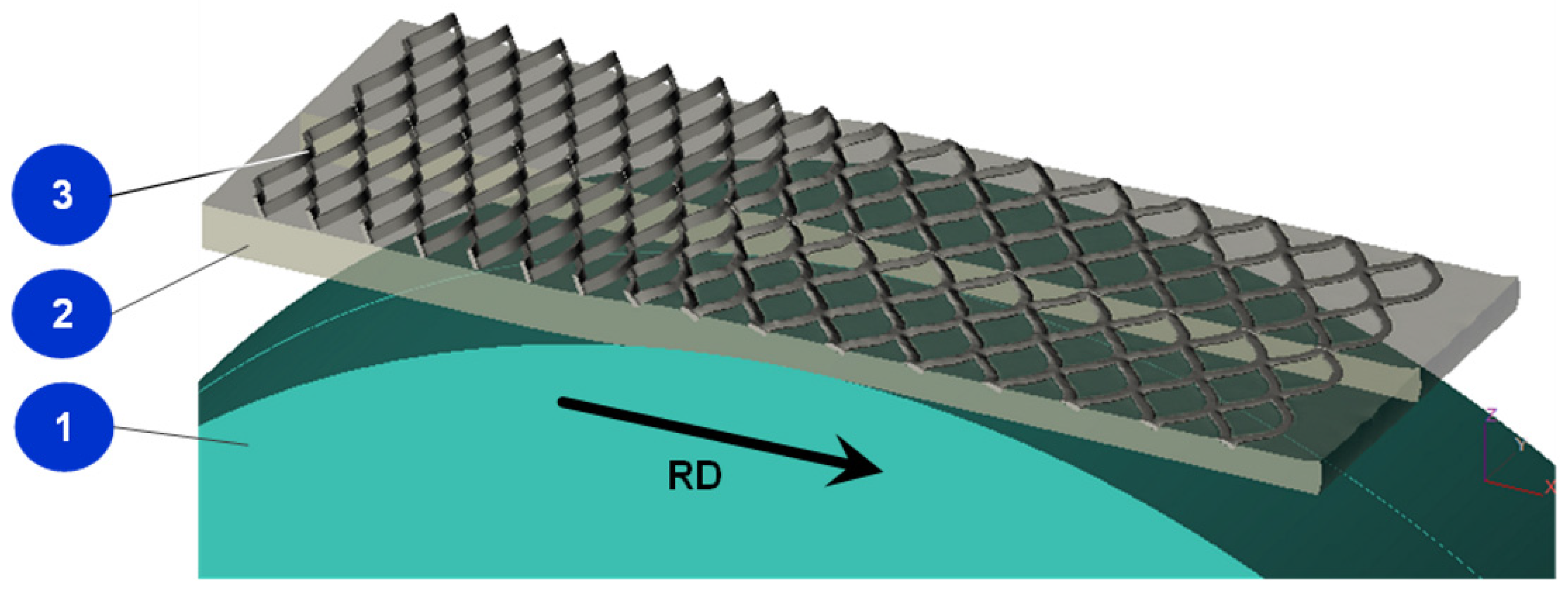
  • outer layers: EN AW 1050 matrix made of hot extruded strip with dimensions (h × b × l) 3 × 70 × 200 mm;
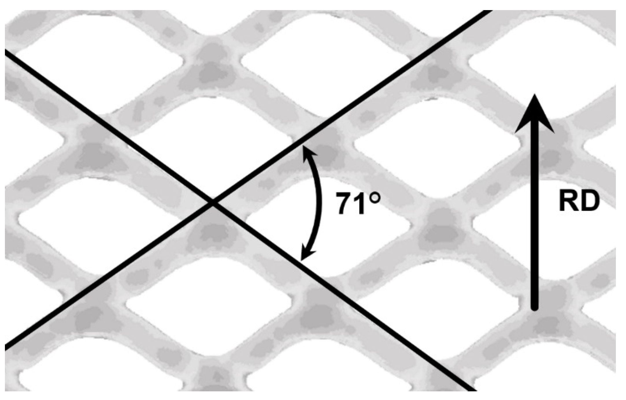
  • inlay: expanded steel mesh of steel C10 (1.0301 by EN 10277-2) with outer dimensions (t × b × l) of 0.5 mm × 70 mm × 200 mm, cell size of 2 mm × 4 mm, and mesh angle (in plane) of 57°.
Assembled billets were jointed and fastened together with aluminum rivets near the corners of each piece. According to the recommendations in [23], the stress relief recrystallisation annealing was applied to steel inlays before assembling. Additionally, the surface brushing of aluminum strips was performed before assembling.

2.2. Experimental Procedure

Experiments were carried out using two different rolling mills with similar rolling reductions to investigate the influence of the deformation zone length on the mesh distortion as well as the properties of rolled composites. The rolling mill with a roll diameter of 200 mm is called “duo”, and the one with a roll diameter of 135 mm “quarto”. Before the roll bonding billets were heated up to 500 °C, the temperature of the metal was controlled with thermocouples placed inside the specimens. All roll bonded composites were additionally exposed to stress relief annealing at 500 °C for 20 min. The same rolling procedure was applied to non-reinforced composites.
Nominal rolling reductions were calculated according to the adapted method [2]:
ε h   c o m p o s i t e = h 0   A l h c o m p o s i t e h 0   A l × 100 %
where h 0   A l is the sum of the thicknesses of both layers of the aluminum matrix, and h c o m p o s i t e is the thickness of the roll-bonded composite. In the presented study, h 0   A l was equal to 6 mm.
The length of the deformation zone was calculated using the following equation:
l d = R r h 0   A l h c o m p o s i t e
where R r is the radius of the rolling roll.
For the average thickness of the composite in the deformation zone:
h ¯ = h 0   A l   + h c o m p o s i t e 2
The form factor of the deformation zone was defined as the ratio
F f = l d h ¯
The detailed rolling schedule and experiment code are presented in Table 1:
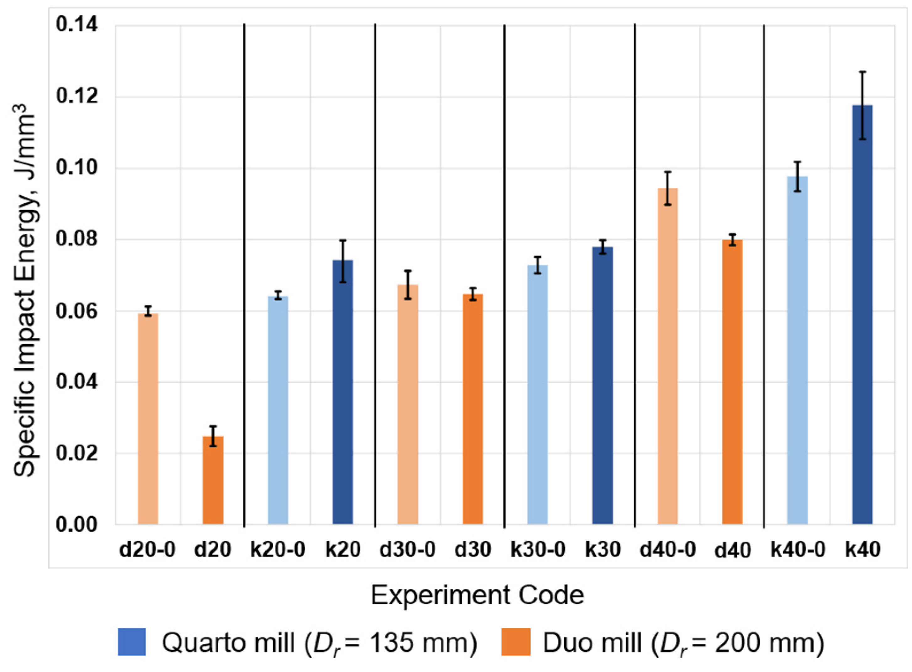
  • “d”—duo (diameter of rolls: 200 mm); “k”—quarto (diameter of rolls: 135 mm);
  • “20”, “30”, and “40”—nominal rolling reduction;
  • “0”—non-reinforced composites.
Each value in Table 1 was calculated as an average value of at least three rolled samples. The discrepancy between the nominal and experimental rolling reductions as well as the final thickness values is caused by the elastic deformation of the mill cage and is more obvious in the case of the duo mill. The transverse flow of the material during roll bonding is considered as negligible because the widening of the composite did not exceed 2.2%, as the mesh inlay prevents the matrix from widening [2].
Analysis of mesh shape change in the composite during roll bonding was performed using X-ray-based micro-CT desktop scanner SkyScan 1275 (µCT) made by Bruker ASX GmbH (Karlsruhe, Germany) with a source power of 10 W and a 1.0 mm copper filter. Specimens of roll-bonded reinforced composites were scanned with a rotation step of 0.4° and a pixel size of 10 µm. The reconstruction from the specimens’ projections to the transverse cross-sections was performed using software NRecon 2.0 by Micro Photonics Inc. Allentown, PA, USA. Subsequently, the cross-sections were processed in the CTAn 1.15 software by Micro Photonics Inc. Allentown, PA, USA to separate the steel mesh and aluminum matrix. Finally, the processed cross-sections were assembled to the volume and captured with the software CTVox 2.2 software by Micro Photonics Inc. Allentown, PA, USA.
The mechanical properties of the composites were analyzed with the help of impact bending tests. They were carried out using a 150 J pendulum impact tester at a room temperature. Specimens were cut to the following dimensions: hcomposite × 20 mm × 55 mm. Such a width of the specimen was chosen to provide the presence of at least 4 complete mesh cells inside. The amount of impact energy absorbed by a composite’s body lied in a range between 11 J and 38 J. Specimens did not fracture during the test procedure. Considering the various thicknesses of the composites, obtained at different rolling reductions, the absorbed energy value was divided by the moment of inertia (Iz) for the rectangle hcomposite × 20 mm, as is recommended in [28]. The moment of inertia was calculated for the initial specimen-to-pendulum contact line. The bending radius and residual bending angle were also measured in the specimens after testing.

2.3. Simulation Procedure

Simulation of the roll bonding process is aimed to gain numerical data regarding the deformation of relatively hard inlays in the relatively soft surrounding of aluminum matrices during the roll bonding process. The unique features of the designed simulation tool are both the consideration of axial flow, as it was presented in [23], and the flattering of expanded mesh in the deformation zone. Figure 1 presents a view of the simulation process, which represents the transformation of Al-steel mesh-Al sandwich to the composite during roll bonding.
The model was validated by comparing the geometrical characteristics of the mesh after the numerical simulation and experimental rolling passes. The finite element (FE) simulation of the roll bonding process was performed using the QForm 9.0.10 software by Micas Simulations Limited, Oxford, UK. QForm is the commercial software designed for the FE mathematical modeling of metal forming processes solving thermomechanical tasks, including the interaction of deformable workpieces with technological tools and equipment [29]. The mathematical basis of the program is a system of equations, which includes the equation of equilibrium, the equation of the relationship between the field of velocities of material points and strain rates, the equation of the relationship between stress and strain, the compression conditions, plasticity, and energy balance equations [25]. The geometry of the rolling rolls, aluminum sheets as well as the mesh were designed using the CAD system. The special subprogram of QForm software was applied for the discretization of geometrical models using tetrahedron finite elements with the following minimal dimensions: half-matrix—0.4 mm; the mesh—0.1 mm; rolls—0.3 mm. The conditions of the simulation correspond to the experimental rolling in the whole range of reductions. The parameters of both the matrix and inlay materials were taken from the program database for aluminum EN AW 1050 and steel 1.0301 correspondingly. The widening of the strip was restricted by frictional reaction stress [30], as the ratio between the initial strip width and the length of the deformation zone (ld) (see Table 1) in most cases didn’t exceed 5. This correlates with the results presented in [2] for reinforced composites. Plane-strain flow was assumed [31], which was supported by the fact that the composite expanded during the experiment insignificantly. To ensure the relative uniform deformation of all components (the mesh inlay and outer layers), the feature “full surface bonding” was applied for the respective interfaces. This allowed us to consider the composite already “joined” before the roll bonding step and to prevent the components from sliding. The friction between the outer matrix surfaces and the rolls was calculated using the Levanov model [32]. The specific friction stress τ was proportional to the maximum shear stress and the friction factor, which takes into account the contact pressure and material flow stress:
τ = m · τ s k · ( 1 e 1.25 · σ n σ s )
where m is the friction factor (m = 0.8 in this study), and τsk is the maximum shear stress at shear:
τ s k = σ s 3
where σn is contact pressure, σs is the material flow stress.
The flow stresses of the C10 steel and EN AW 1050 alloy were adjusted by means of the Hensel-Spittel model [33,34], which considers initial strain resistance, temperature, strain, and strain rate, and is defined as follows:
σ s = A · e m 1 · T · ε m 2 · e m 4 / ε · ( 1 + ε ) m 5 · T · e m 7 · ε · ε ˙ m 8 · T
where A is constant; m1 to m8 are coefficients considering the influence of the current deformation conditions on the flow stress (Table 2), T is the deformation temperature, ε is strain, and ε ˙ is the strain rate.
To calculate the deformation of the composite components, the effective plastic strain was applied in the simulation. It is defined as:
ε ¯ e f p = l d ε ¯
where ε ¯ is the strain intensity, which is defined as:
ε ¯ = 2 3 ( ε x ε y ) 2 + ( ε y ε z ) 2 + ( ε z ε x ) 2 + 3 2 ( γ x y 2 + γ y z 2 + γ z x 2 )
where εxy, εz, γxy γyz γzx are corresponding components of the plastic strain tensor; the Hencky finite strain tensor was used in the QForm software.
The thermal conductivity model is defined as:
k ( 2 T x 2 + 2 T y 2 + 2 T z 2 ) + q G = p c T t
where k is the thermal conductivity coefficient (k = 217 W/mK here), T is temperature, p is density (kg/m3), c is specific heat (J/kgK), t is time (s), and qG is the power of the distributed volumetric heat source. The last one is defined as the sum of the power of the external heat source unit qν (given by the initial data) and the heat generation caused by the plastic deformation qp, which can be defined as follows:
q p = β p σ ¯ ε ¯ ˙
where βp is the deformation-into-heat transformation coefficient (0.9 in this study), σ ¯ is the effective strain, and ε ¯ ˙ is the effective strain rate.
Fourier’s law was used to determine the boundary conditions:
q n = k T n
where n is the surface which is normal to the heat transfer direction, and qn is the thermal flux through the heat transfer surface, which is the sum of the convection heat transfer and radiation heat transfer at the surface of the composite and roll. The Newton-Richman law was used for the calculation of the convective heat transfer between the rolls and the outer layers of the composite:
q n = b α Δ T ,
where α is the heat transfer coefficient (α = 100,000 W/m2K here), b is the coefficient which shows how the heat transfer rate should be reduced in the absence of tight contact between the workpiece and the tool, ΔT is the temperature difference between the tools and the workpiece.
The radiation heat transfer is defined as:
q n r = ε σ 0 ( T 1 4 T C 4 )
where ε is the real body emissivity factor (the ratio of the given body emissivity to the absolute black body emissivity at the same temperature), σ0 = 5.67·10−8 W·m−2·K−4 is the Stefan–Boltzmann constant, T1 is absolute body temperature, and Tc is absolute environment temperature.

3. Results and Discussion

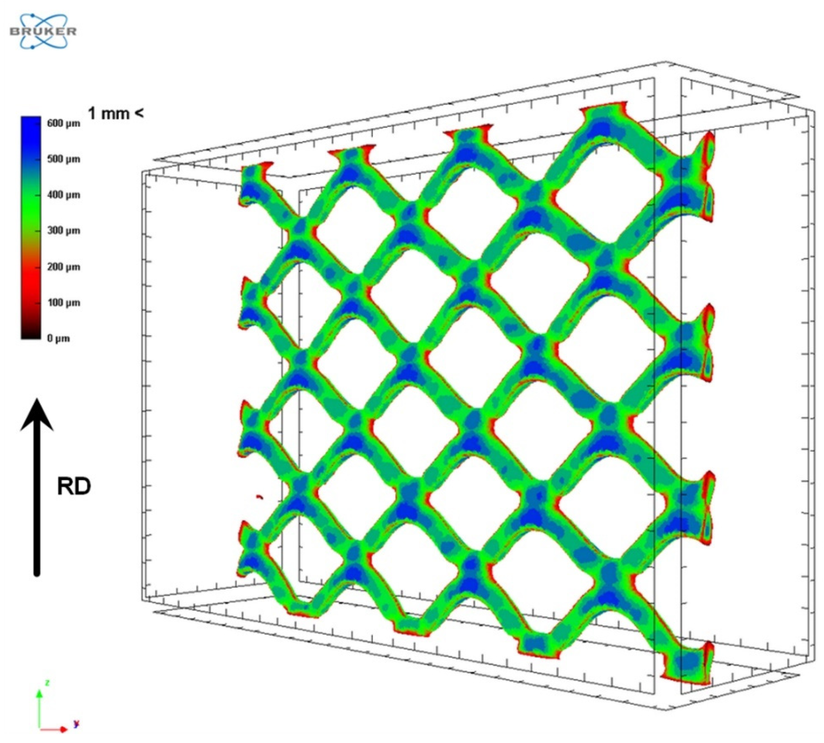
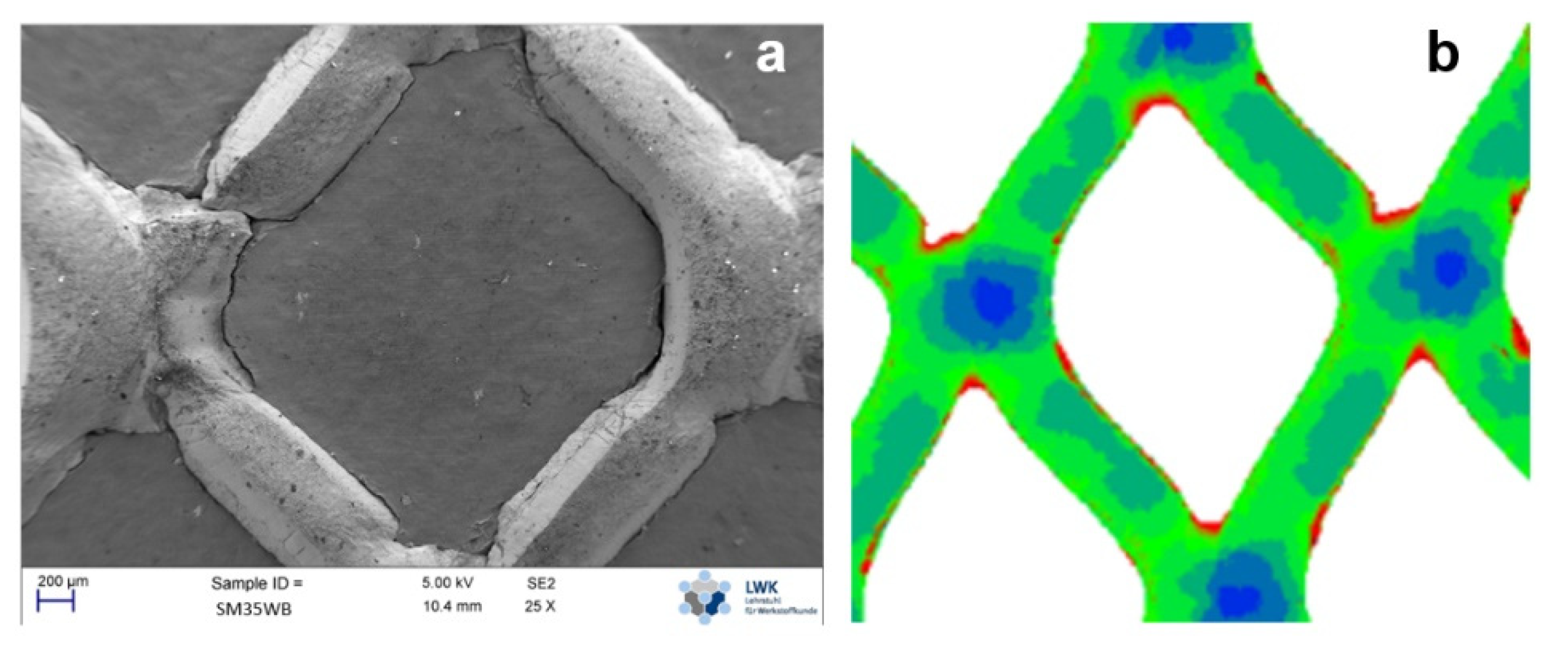
3.1. µCT-Imaging of Roll Bonded Composites

Three-dimensional reconstruction of the scanned composites simplifies the analysis of the deformation of the inlay through the mesh angle observation. A general view of the reinforcing mesh inside the roll bonded composite is presented in Figure 2. The reconstruction also shows the range of thicknesses of the mesh elements.
As concluded in [28], the change in the mesh angle is the major parameter of the inlay deformation during roll bonding. However, it loses the dominating role with an increase in rolling reduction. Figure 3 shows the procedure for measuring the mesh angle with the help of plane projection from µCT scans in order to calculate the mesh deformation.
Values of the measured mesh angle as well as its increment divided by the rolling reduction are presented in Table 3. These values allow for the estimation of the change of the mesh angle depending on the reduction and the diameter of the rolls. An increase in rolling reduction in the range between 20% and 40% continuously increases the mech angle. The increment of the mesh angle stops at 50% reduction in the case of the rolling mill “quarto”, which was observed after one additional experiment series. Roll bonding using the “duo” mill leads to lower values of the mesh angle increment within the whole range of reductions.
Despite the volume fraction of the reinforcing inlay according to the volume constancy remaining unchangeable and equaling 4.4 ± 0.5% in this study, the portion of the mesh in the composite’s thickness grew with increasing rolling reduction. Such an effect is explained by the turning of the mesh as well as by the above mentioned increment of the mesh angle. Besides the angle evaluation, reconstruction of the mesh inside the roll-bonded composite with the help of µCT-scans allowed for the detection of possible defects and failures. In general, all scanned specimens retained integrity of the mesh body after roll bonding (Figure 4). Visible hotspots of localized deformation were observed both after roll bonding with a nominal reduction of 40% using the “duo” mill, and with a nominal reduction of 50% using the “quarto” mill. It is relevant to highlight here that such hotspots were not observed after roll bonding with a nominal reduction of 40% using the “quarto” mill.

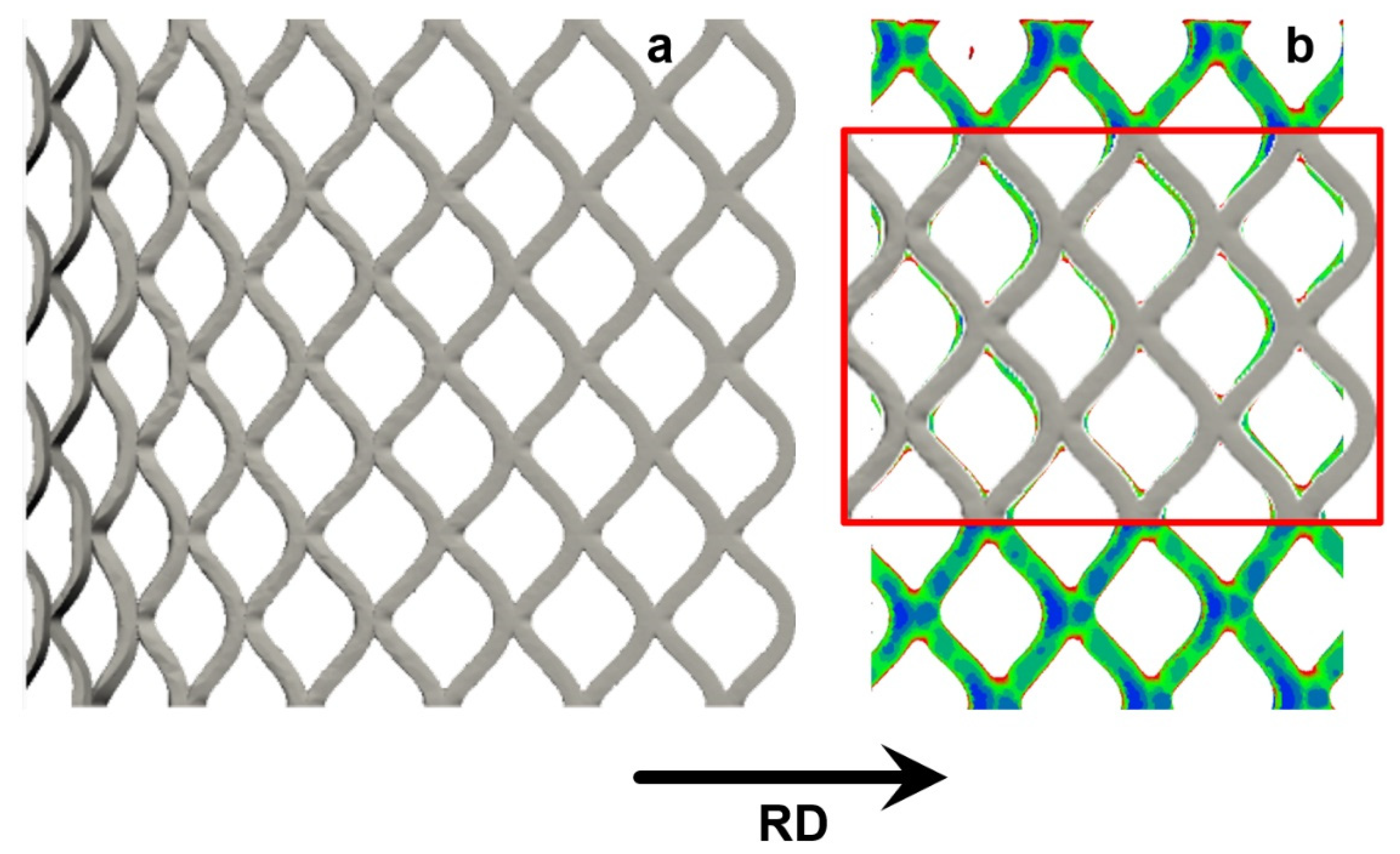
3.2. FE Simulation Using QForm Software

The novelty of the simulation section of this study consists in designing the FE model to predict the 3D deformation steel mesh surrounded by aluminum sheets during roll bonding. The following aspects are considered in this model:
  • The nonaxial stretching of the mesh in the initial stage;
  • The alignment of the mesh parallel to the rolling direction;
  • The change in the mesh angle inside the deformation zone;
  • The thinning and flattering of the mesh components.
Figure 5 demonstrates the plane projection of the mesh inside the deformation zone during roll bonding using the “quarto” mill with a nominal reduction of 40% (a). Comparison of the simulation and experimental results allows us to conclude that the change in the mesh angle inside the deformation zone in the designed FE model precisely reproduces our experimental result (Figure 5b). The evaluation of the thinning and flattering of the mesh components in the FE model and their comparison with experimental data will be performed within the scope of future work.
The experimentally revealed and simulated mesh angles are in good agreement with each other in the range of rolling reductions between 20% and 30% (“duo”), and between 20% and 40% (“quarto”). Higher deviations in the mesh angle calculations might be a result of localized deformation in the inlay’s body and the beginning of fractures which took place in the experiments d40 and k50. Simulation of the near-fracture area is a bottleneck of software developed for the calculation of plastic deformation.

3.3. Impact Bending Tests

Impact bending tests were carried out for both the reinforced and non-reinforced composites manufactured with 20%, 30%, and 40% reductions (see Table 1). The results of this testing are summarized in Figure 6.
An increase of rolling reductions improves the specific impact energy in all tested samples. Furthermore, a smaller roll diameter results in better values of the specific impact energy, independent of the composite type and rolling reduction. Simultaneously, the following differences between the “duo” and “quarto” mills can be highlighted:
  • The “duo” mill provides a higher increase of specific impact energy in non-reinforced composites;
  • Roll bonding in the “quarto” mill increases the specific impact energy in reinforced composites.

3.4. Discussion

The novelty of the data presented in this manuscript consists of the development of a FE simulation of the complex process of roll bonding, with a focus on the 3D transformation of a deformable hard inlay in a soft surrounding aluminum matrix. Our other two findings answer more practical questions:
  • How does the diameter of rolls influence the mechanical performance of composites?
  • Is it possible to use relatively cheaper construction steel instead of stainless steel as an inlay for reinforcing?
Considering the results presented in [35], and taking into account the relative portion of the mesh in the composite’s body (see Table 3), which does not exceed 5%, the composites in the current study can be classified as lightly reinforced composites. For such composites, defects occurring on their inner interfaces can outweigh the strength of the reinforcing component. Simultaneously, the relatively low content of the reinforcing inlay does not increase the specific weight of the composite. According to the data presented in Table 3, the theoretical specific weight of the reinforced composites increases for app. 8% up to 2.9 gr/mm3. This highlights the importance of appropriate deformation parameters during the roll bonding, which allows for the design and manufacturing of lightly reinforced composites. The presented results (see Figure 6) allow us to conclude that roll bonding using the “duo” mill does not meet such requirements. Obviously, this is because the length of the deformation zone are app. 20% greater than in the “quarto” mill (see Table 1). This difference was observed in the entire range of reductions. The elevated length of the deformation zone hinders the movement of the inner layers of the composite alongside the rolling direction due to the higher friction force, which is in agreement with the results presented in [36]. The so-called sticking zone shifts the deformation to the exit of the rolling gap, where the axial tensile stress increases rapidly. Such conditions facilitate the delamination between adjacent layers, as shown in [4]. In accordance with [23], Figure 7 demonstrates a case where the residual ductility of the mesh inlay is too low, due to strain hardening during previous stages of manufacturing (a). Another example (b) represents a situation where the intensity of tension caused by the increased sticking zone is too high (b) (see Table 1, d40).
In contrast to the “duo” mill, the “quarto” mill, with a shorter length of the deformation zone, allows us to avoid the abrupt transition from the sticking zone with high hydrostatic pressure to the axial tension at the exit from the rolling gap. This keeps the inlay intact, and, especially at a sufficient reduction, leads to the rise of impact properties of app. 20%.
Thus, the value of the mesh angle can be considered as a criterion for sufficient rolling reduction. Here, the angle should be as close as possible to 90°. However, the localization of deformation in certain zones of the mesh is a restricting parameter (see Figure 4 and Figure 5). Comparison of the results of the current study (inlay made of C10 ferritic-pearlitic steel expanded mesh) with results published in [23] (inlay-AISI 304 austenitic steel expanded mesh) allows us to conclude that the mesh angle of the inlay made of construction steel is two times less sensible to the rolling reduction. Generally, the quantitative evaluation of that difference can be described as follows: each percent of rolling reduction applied to composites reinforced with austenitic steel mesh increases the mesh angle by one degree. In the case of ferritic-pearlitic steel, two percent of reduction is necessary to achieve the same result. Qualitative as well as quantitative data obtained in this study allowed us to identify tools which improve the impact properties of aluminum-steel mesh-aluminum composites:
-
The enhancement of the volumetric part of reinforcement (pilot experiments show that content of the expanded mesh up to 20% does not significantly spoil the outer surface);
-
The application high-strength Al-alloys;
-
The application of innovative alloys and technologies, e.g., the additive manufacturing of the inlay. Finally, reinforced composites have the potential to serve as fire-resistant materials, for which performance in flames depends on the geometry and properties of the inlay.

4. Conclusions

  • The behavior of the expanded mesh of the construction steel during roll bonding between two aluminum sheets was successfully analyzed by the designed simulation model and validated by the experimental date.
  • The designed FE model for the prediction of the 3D deformation of the steel mesh in roll-bonded composites considers the following aspects: the nonaxial stretching of the mesh in the initial stage; the alignment of the mesh along the rolling direction; the change in the mesh angle inside the deformation zone; the thinning and flattering of the mesh components.
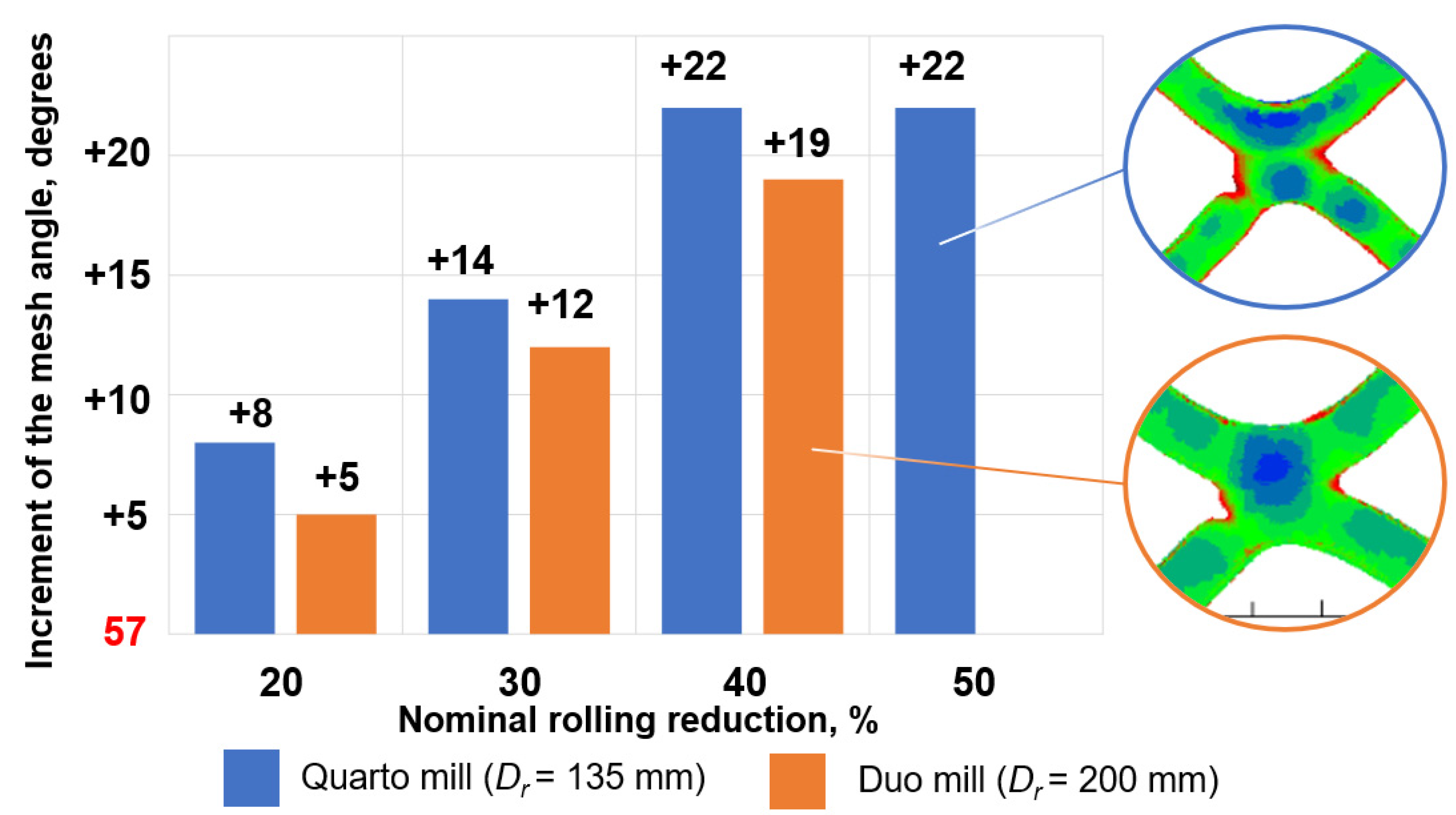
  • Roll bonding experiments with a temperature of 500 °C using two separate rolling mills with rolls with a diameter of 135 mm and 200 mm, respectively, were performed to investigate the influence of the length of the deformation zone on the mesh distortion as well as on the properties of the roll-bonded composites. It has been revealed that the mesh angle of the inlay of ferrite-pearlite steel is two times less sensible to the rolling reduction in comparison with a similar mesh of austenitic steel.
  • The distortion of the mesh was analyzed using computer tomography scanning and subsequently evaluated via the increment of the angle between mesh strands.
  • Lightly reinforced composites with a relative part of the reinforcing component below 5% are sensitive to deformation parameters during roll bonding. Not only rolling reduction and temperature, but also the length of the deformation zone related to the diameter of rolls influences a composite’s impact properties.
  • The elevated length of the deformation zone hinders the movement of the inner layers of the composite alongside the rolling direction due to friction force. The so-called sticking zone shifts the deformation to the exit of the rolling gap, where the axial tensile stress increases rapidly. Such conditions facilitate the delamination between adjacent layers.
  • Lightly reinforced composites in this study exhibit better impact properties in comparison with non-reinforced ones. The maximal rise of specific impact energy for 20% exhibits the reinforced composite rolled with a rolling reduction of 40% using a mill with smaller rolls. A similar reduction applied to the composite in the mill with greater rolls significantly deteriorates the impact properties.

Author Contributions

Y.F. developed the roll bonding process of the reinforced composites, contributed to the interpretation of results, and participated in the writing of the manuscript, M.N. and O.R. conducted the experimental procedures, A.S. and O.B. created the FE model, contributed to the interpretation of results, and participated in the writing of the manuscript. All authors have read and agreed to the published version of the manuscript.

Funding

This research was partially funded by the National Research Foundation of Ukraine, grant “Development of end-to-end roll-bonding technology for reinforced Al-based composites with enhanced ability to impact energy absorption as well as the fire resistance” (number 2020.02/0329).

Institutional Review Board Statement

Not applicable.

Informed Consent Statement

Not applicable.

Data Availability Statement

No new data were created or analyzed in this study. Data sharing is not applicable to this article.

Conflicts of Interest

The authors declare no conflict of interest.

References

  1. Stolbchenko, M.; Makeieva, H.; Grydin, O.; Frolov, Y.; Schaper, M. Roll Bonding of Steel Net-Reinforced Aluminium Strips. Mat. Res. 2018, 21, 1–11. [Google Scholar] [CrossRef] [Green Version]
  2. Stolbchenko, M.; Makeieva, H.; Grydin, O.; Frolov, Y.; Schaper, M. Strain parameters at hot rolling of aluminum strips reinforced with steel netting. J. Sandw. Struct. Mater. 2020, 22, 2009–2029. [Google Scholar] [CrossRef]
  3. Huang, H.; Wang, J.; Liu, W. Mechanical properties and reinforced mechanism of the stainless steel wire mesh–reinforced Al-matrix composite plate fabricated by twin-roll casting. Adv. Mech. Eng. 2017, 9, 168781401771663. [Google Scholar] [CrossRef]
  4. Frolov, Y.; Stolbchenko, M.; Grydin, O.; Makeeva, H.; Tershakovec, M.A.; Schaper, M. Influence of strain parameters at rolling on the properties of wire-reinforced aluminium composites. Int. J. Mater. Form. 2019, 12, 505–518. [Google Scholar] [CrossRef]
  5. Gülenç, B.; Kaya, Y.; Durgutlu, A.; Gülenç, İ.; Yıldırım, M.S.; Kahraman, N. Production of wire reinforced composite materials through explosive welding. Arch. Civ. Mech. Eng. 2016, 16, 1–8. [Google Scholar] [CrossRef]
  6. Hufenbach, W.; Ullrich, H.; Gude, M.; Czulak, A.; Malczyk, P.; Geske, V. Manufacture studies and impact behaviour of light metal matrix composites reinforced by steel wires. Arch. Civ. Mech. Eng. 2012, 12, 265–272. [Google Scholar] [CrossRef]
  7. Ferro, P.; Fabrizi, A.; Bonollo, F.; Berto, F. Microstructural and mechanical characterization of a stainless-steel wire mesh–reinforced Al-matrix composite: Bimatallic components for lightweight design. Frat. Integrità Strutt. 2021, 15, 289–301. [Google Scholar] [CrossRef]
  8. Haranich, Y.; Frolov, Y.; Gridin, O.; Voswinkel, D.; Boiarkin, V.; Remez, O. Hot roll bonding of aluminum flat composite material with steel mesh inlays. Theory Pract. Metall. 2018, 6, 34–39. [Google Scholar] [CrossRef]
  9. Haranich, Y.; Frolov, Y.; Grydin, O.; Voswinkel, D.; Andreiev, A.; Remez, O. Failure mode of reinforcing steel mesh in aluminum roll bonded composite material. Theory Pract. Metall. 2019, 1, 29–34. [Google Scholar] [CrossRef]
  10. Frolov, Y.V.; Mamuzić, I.; Danchenko, V.N. The heat conditions of the cold pilger rolling. Metals 2006, 45, 179–184. Available online: https://hrcak.srce.hr/6486 (accessed on 24 May 2021).
  11. Grydin, O.; Stolbchenko, M.; Schaper, M. Twin-Roll Casting of Carbon Fiber-Reinforced and Glass Fiber-Reinforced Aluminum Strips. In Light Metals 2016; Williams, E., Ed.; Springer International Publishing: New York, NY, USA, 2016; pp. 1007–1012. ISBN 978-3-319-48615-4. [Google Scholar] [CrossRef]
  12. Eizadjou, M.; Danesh Manesh, H.; Janghorban, K. Investigation of roll bonding between aluminum alloy strips. Mater. Des. 2008, 29, 909–913. [Google Scholar] [CrossRef]
  13. Chen, G.; Li, J.T.; Yu, H.L.; Su, L.H.; Xu, G.M.; Pan, J.S.; You, T.; Zhang, G.; Sun, K.M.; He, L.Z. Investigation on bonding strength of steel/aluminum clad sheet processed by horizontal twin-roll casting, annealing and cold rolling. Mater. Des. 2016, 112, 263–274. [Google Scholar] [CrossRef]
  14. Eizadjou, M.; Danesh Manesh, H.; Janghorban, K. Mechanism of warm and cold roll bonding of aluminum alloy strips. Mater. Des. 2009, 30, 4156–4161. [Google Scholar] [CrossRef]
  15. Akramifard, H.R.; Mirzadeh, H.; Parsa, M.H. Cladding of aluminum on AISI 304L stainless steel by cold roll bonding: Mechanism, microstructure, and mechanical properties. Mater. Sci. Eng. A 2014, 613, 232–239. [Google Scholar] [CrossRef]
  16. Danesh Manesh, H.; Karimi Taheri, A. The effect of annealing treatment on mechanical properties of aluminum clad steel sheet. Mater. Des. 2003, 24, 617–622. [Google Scholar] [CrossRef]
  17. Yahiro, A.; Masui, T.; Yoshida, T.; Doi, D. Development of Nonferrous Clad Plate and Sheet by Warm Rolling with Different Temperature of Materials. ISIJ Int. 1991, 31, 647–654. [Google Scholar] [CrossRef]
  18. Jamaati, R.; Toroghinejad, M.R. Investigation of the parameters of the cold roll bonding (CRB) process. Mater. Sci. Eng. A 2010, 527, 2320–2326. [Google Scholar] [CrossRef]
  19. Soltani, M.A.; Jamaati, R.; Toroghinejad, M.R. The influence of TiO2 nano-particles on bond strength of cold roll bonded aluminum strips. Mater. Sci. Eng. A 2012, 550, 367–374. [Google Scholar] [CrossRef]
  20. Chaudhari, G.P.; Acoff, V. Cold roll bonding of multi-layered bi-metal laminate composites. Compos. Sci. Technol. 2009, 69, 1667–1675. [Google Scholar] [CrossRef]
  21. Abbasi, M.; Toroghinejad, M.R. Effects of processing parameters on the bond strength of Cu/Cu roll-bonded strips. J. Mater. Process. Technol. 2010, 210, 560–563. [Google Scholar] [CrossRef]
  22. Haranich, Y.; Frolov, Y. Comprehensive analysis of metal–polymer sandwich composite manufacturing. Mater. Work. Press. 2017, 136–141. Available online: http://www.dgma.donetsk.ua/science_public/omd/omd_2(45)_2017/article/24.pdf (accessed on 24 May 2021).
  23. Frolov, Y.; Haranich, Y.; Bobukh, O.; Remez, O.; Voswinkel, D.; Grydin, O. Deformation of expanded steel mesh inlay inside aluminum matrix during the roll bonding. J. Manuf. Process. 2020, 58, 857–867. [Google Scholar] [CrossRef]
  24. Rodman, D.; Boiarkin, V.; Nürnberger, F.; Dalinger, A.; Schaper, M. Modeling of Spray Cooling during Induction Hardening of Spur Gearwheels Made from 42CrMo4 Hardening and Tempering Steel. Steel Res. Int. 2014, 85, 741–755. [Google Scholar] [CrossRef]
  25. Gerasimov, D.; Biba, N.; Stebunov, S.; Kadach, M. Implementation of a Dual Mesh Method for Longitudinal Rolling in QForm V8. MSF 2016, 854, 158–162. [Google Scholar] [CrossRef] [Green Version]
  26. Rozylo, P.; Ferdynus, M.; Debski, H.; Samborski, S. Progressive Failure Analysis of Thin-Walled Composite Structures Verified Experimentally. Materials 2020, 13, 1138. [Google Scholar] [CrossRef] [PubMed] [Green Version]
  27. Debski, H.; Rozylo, P.; Teter, A. Buckling and limit states of thin-walled composite columns under eccentric load. Thin-Walled Struct. 2020, 149, 106627. [Google Scholar] [CrossRef]
  28. Stolbchenko, M.; Frolov, Y.; Makeieva, H.; Grydin, O.; Tershakovec, M.A.; Schaper, M. The mechanical properties of rolled wire-reinforced aluminum composites at different strain values. Mech. Adv. Mater. Struct. 2020, 27, 1599–1608. [Google Scholar] [CrossRef]
  29. QForm, version 9.0.10. Windows; Micas Simulations Limited: Oxford, UK.
  30. Danchenko, V.M.; Grykevich, V.O.; Golovko, O.M. Teoriya Protsesiv Obrobky Metaliv Tyskom (Theory of Metalls Treatment with Pressure); POROHY: Dnipropetrovsk, Ukraine, 2008; ISBN 978-996-525-968-8. [Google Scholar]
  31. Lenard, J.G. Primer on Flat Rolling, 2nd ed.; Elsevier: Amsterdam, The Netherlands, 2013; ISBN 978-0-08-099418-5. [Google Scholar]
  32. Levanov, A. Improvement of metal forming processes by means of useful effects of plastic friction. J. Mater. Process. Technol. 1997, 72, 314–316. [Google Scholar] [CrossRef]
  33. Spittel, M.; Spittel, T. Steel symbol/number: C10/1.0301. In Metal Forming Data of Ferrous Alloys—Deformation Behaviour; Martienssen, W., Warlimont, H., Eds.; Springer: Berlin, Germany, 2009; pp. 144–149. ISBN 978-3-540-44758-0. [Google Scholar] [CrossRef]
  34. Spittel, M.; Spittel, T. Al 99.5. In Part 2: Non-Ferrous Alloys—Light Metals; Martienssen, W., Warlimont, H., Eds.; Springer: Berlin, Germany, 2011; pp. 197–203. ISBN 978-3-642-13863-8. [Google Scholar] [CrossRef]
  35. Heinrich, W.; Nixdorf, J. Die Faser- und Fadenverstärkung von plastischen und spröden Matrixmaterialien. Materwiss Werksttech. 1971, 2, 398–405. [Google Scholar] [CrossRef]
  36. Wang, J.; Liu, X.; Sun, X. Study on asymmetrical cold rolling considered sticking friction. J. Mater. Res. Technol. 2020, 9, 14131–14141. [Google Scholar] [CrossRef]
Figure 1. View of the simulation model cut. 1: roll, 2: aluminum layer; 3: steel mesh; RD: rolling direction.
Metals 11 01044 g001
Figure 2. General view of reinforcing mesh inside the roll-bonded composite; RD: rolling direction.
Metals 11 01044 g002
Figure 3. Example of the change of the mesh angle during roll bonding on the plane projection of the µCT-image; RD: rolling direction.
Metals 11 01044 g003
Figure 4. Visualization of the increment of the inlay mesh angle after roll bonding with various reductions using two types of rolling mills: the rolling mill with a roll diameter (Dr) of 200 mm is called “duo”, the mill with (Dr) of 135 mm “quarto”. The left part shows the hotspots of the localized deformation near mesh knuckles.
Metals 11 01044 g004
Figure 5. The transformation of expanded mesh geometry as a reinforcing component during the roll bonding of the aluminum matrix: (a) development of the mesh geometry along the deformation zone (rolling reduction 40%, “quarto” mill) obtained after the FE simulation using QForm 9.0.10 software; (b) the fragment of simulated geometry overlapping with the CT reconstruction image of the mesh inlay after the experimental rolling of the aluminum composites.
Metals 11 01044 g005
Figure 6. The specific impact energy absorbed by both non-reinforced and reinforced composites roll bonded with nominal reductions of 20%, 30%, and 40% using two types of rolling mills. Letters “d” and “k” mean the type of the rolling mill: “d” is duo (diameter of rolls: 200 mm) and “k” is quarto (diameter of rolls: 135 mm); numbers 20, 30 and 40 point to the nominal rolling reduction; “0” is the marker for non-reinforced composites.
Metals 11 01044 g006
Figure 7. Images of inlay failure after roll bonding: (a) according to [23], where failure was caused by the use of non-annealed expanded mesh; (b) localized deformation in the annealed mesh inlay as a consequence of the elevated length of the deformation zone in the “duo” mill (see Table 1, experiment code d40).
Metals 11 01044 g007
Table 1. Nominal and experimental thicknesses of roll-bonded composites: h0 Al—the sum of the thicknesses of both layers of the aluminum matrix; hcomposite—thickness of the roll-bonded composite εhcomposite—rolling reduction of whole composite (1); ld—the length of the deformation zone (2); h ¯ —the average thickness of the composite in the deformation zone (3); Ff—the form factor of the deformation zone (4).
Experiment Codeh0 Al
mm
Nominal
hcomposite mm
In Fact
hcomposite
mm
In Fact
εhcomposite
%
Calculated
ld
mm
Calculated
h ¯
mm
Calculated
Ff
d20-06.004.804.8519.2010.725.431.98
d206.004.804.8718.8010.635.441.96
k20-06.004.804.8519.208.815.431.62
k206.004.804.8718.808.735.441.61
d30-06.004.204.3327.8912.925.172.50
d306.004.204.3527.5312.845.182.48
k30-06.004.204.2828.5910.775.142.10
k306.004.204.3128.2410.685.162.07
d40-06.003.603.7836.9514.904.893.05
d406.003.603.8036.6414.834.903.03
k40-06.003.603.7138.1812.434.862.56
k406.003.603.7337.8812.384.872.54
Table 2. Coefficients of the Hensel-Spittel model for the components of the roll bonded composite: A : material constant; m1 to m8: coefficients considering the influence of the current deformation conditions on the flow stress.
MaterialAm1m2m4m5m7m8
EN AW 1050367.651−0.004630.329110.00167−0.002070.165920.000241
1.03012171.12−0.002220.420560.00117−0.002200.515860.000145
Table 3. Measured parameters of the mesh changes during the roll bonding: the mesh angle and the part of the mesh in the composite’s thickness occupied with reinforcing mesh after experimental rolling.
Experiment CodeInitial Mesh Angle,
Degrees
Final Mesh
Angle
(Experiment),
Degrees
Increment of the Mesh Angle Per Percent of Rolling Reduction (Experiment)Final Mesh Angle (Simulation),
Degrees
Increment of the Mesh Angle Per Percent of Rolling Reduction (Simulation)Part of the Mesh in Composite’s Thickness
d2057620.27630.300.08
k2057650.42640.350.10
d3057690.44720.500.09
k3057710.5720.500.10
d4057760.52820.630.09
k4057790.58830.650.11
k50 *57790.46970.800.12
* Additional experimental rolling with a nominal reduction of 50% using the “quarto” mill.
Publisher’s Note: MDPI stays neutral with regard to jurisdictional claims in published maps and institutional affiliations.

