Article

Grain Structure Evolution and Mechanical Properties of Multi-Channel Spiral Twist Extruded AA5083

by
Dina M. Fouad
1,
Waleed H. El-Garaihy
2,3,*,
Mohamed M. Z. Ahmed
4,5,
Ibrahim Albaijan
4,
Mohamed M. El-Sayed Seleman
5 and
Hanadi G. Salem
1
1
Mechanical Engineering Department, The American University in Cairo, Cairo 11835, Egypt
2
Mechanical Engineering Department, College of Engineering, Qassim University, Unsaizah 51911, Saudi Arabia
3
Mechanical Engineering Department, Suez Canal University, Ismailia 41522, Egypt
4
Mechanical Engineering Department, College of Engineering, Prince Sattam Bin Abdulaziz University, Al Kharj 16273, Saudi Arabia
5
Metallurgical and Materials Engineering Department, Faculty of Petroleum and Mining Engineering, Suez University, Suez 43511, Egypt
*
Author to whom correspondence should be addressed.
Metals 2021, 11(8), 1276; https://doi.org/10.3390/met11081276
Submission received: 13 July 2021 / Revised: 10 August 2021 / Accepted: 10 August 2021 / Published: 12 August 2021

Abstract

:
This study presents a comprehensive evaluation of the effects of multi-channel spiral twist extrusion (MCSTE) processing on the mechanical properties and structural evolution of AA5083. The structural evolution and texture developed were mapped by electron backscatter diffraction (EBSD) for three successive passes and compared with an as-annealed plate. An evaluation of the hardness and tensile properties was presented and correlated with the EBSD findings. The displayed EBSD results revealed that grain refinement was strongly associated with the presence of a high density of low-angle grain boundaries (LAGBs) after one pass, which developed into fine grains of less than 20 μm and high-angle grain boundaries (HAGBs) after three MCSTE passes. The three pass processing led to a 65% reduction in grain size. This reduction in grain size was coupled with an enhancement in the hardness and tensile properties. Additionally, the crystallographic texture study represented a slightly random texture due to the presence of intermetallic particles in AA5083. This study demonstrates the efficacy of MCSTE as a grain refinement tool.

1. Introduction

Over the past two decades, extensive research has been conducted and advancements have been made in the fabrication of bulk ultrafine grained (UFG) structures with optimized properties [1,2]. Owing to their superior properties and unique attributes, grain refinement processes have gained the attention of researchers and scientists worldwide. Among the various physical properties, the microstructural characteristics, specifically grain size and structure, both have a pivotal function in governing the mechanical properties and overall characteristics of metals and alloys [3]. Hence, it has become intrinsically important to intensify the research conducted on “top down” severe plastic deformation (SPD) processes, as they provide an optimal approach to producing UFG structures without porosity or contamination compared to their counterpart “bottom-up” methods [2]. Concurrently, several SPD processes have been devised with the perpetual aim of grain refinement and simultaneous boundary strengthening [1,2,3,4,5,6,7,8,9,10,11,12,13,14].
By imposing substantial strain and imposing high levels of deformation at room temperature or cold working conditions, SPD techniques are able to attain UFG structures with average crystal sizes less than 1 μm, enabling them to benefit from the Hall-Petch strengthening effect [15]. More importantly, aluminum (Al) alloys have been particularly known to benefit from such a phenomenon, where several articles have suggested grain refinement as a prime hardening mechanism for Al alloys [1,16]. Concurrently, given its abundance in nature and light weight properties, the processing of Al alloys via various SPD processing techniques has been extensively presented in the literature with the aim of achieving higher specific strength properties favorable for automotive and aerospace applications [17,18]. Subsequently, strain hardening via SPD processes provides a highly effective and inevitable approach to enhance the strength of non-heat-treatable aluminum alloys, with several articles reporting promising enhancement in 5xxx series Al alloys such as AA5083 [1,17,18,19,20]. It is worth to mentioning here that, 5xxx series aluminum alloys constitute the highest strength Al alloys in the non-heat-treatable category coupled with a good weldability and corrosion resistance which supports its use in the automotive and aircraft industries [19].
Among the various most established SPD methods, the deformation of AA5083 via Equal Channel Angular pressing ECAP has been significantly investigated in the literature [1,17]. With the ability to impose high levels of strain and process large samples, ECAP offers several processing advantages necessary for industrial uptake [20]. Stolyarov and Lapovok processed AA5083 via three ECAP passes and achieved significant enhancement in the mechanical properties, which resulted in an average yield strength (YS) of 364 MPa, ultimate tensile strength (UTS) of 423 MPa and a significant reduction in ductility to 7.75% [17]. However, despite the enhancement of tensile properties, ductility is compromised, and while that still remains a challenge, researchers have applied post-processing techniques to enhance the results and retain toughness [15]. For instance, Jin et al. applied warm rolling and annealing on ECAPed AA5083 as a means of achieving a strong and tough material [20]. Nevertheless, despite its potential, unnecessary post-processing treatments impose additional costs in operation that limit the process and render it unfavorable for industrial operations. Additionally, other established SPD processes, such as high-pressure torsion (HPT), suffer from a major drawback: even though it induces the highest strain accumulation within a deformed material, its small size limitation hinders its upscaling and application [15]. Furthermore, during the past decade, twist extrusion (TE) was introduced as a means of combining the benefits of shear and torsion SPD-based deformation processes, which enables an unprecedented ability to process several solid and hollow cross-sections except circular cross-sections [21]. Based on its promising potential and superior industrial capabilities, several recent modifications based on TE straining principles have been devised, such as twist angular pressing (TCAP) [22], hollow twist extrusion [23], online twist extrusion [24], and planar twist extrusion [25]. However, most of these variants have been primarily designed to increase the induced strain and the ability to process specific cross-sections while neglecting financial feasibility aspects such as die cost and die durability. These elements are highly valued for industrial upscaling alongside the high power consumed due to the application of high backpressure (BP). A critical issue is the amount of BP induced in shear-based processes such as ECAP and TE, whereas several studies have demonstrated undesirable structures and skewed cross-sections when insufficient BP is applied [3,26]. Consequently, multi-channel spiral twist extrusion (MCSTE) has been introduced by the authors as a cost-saving and versatile variant to TE, which applies minimum BP, on a variety of solid and hollow cross-sections with the aid of a mandrel encompassed through a set of customizable stacks of disks, as illustrated in Figure 1a, and a reduced twist angle. Full details of the novel design are available in [27]. It is worth noting that in MCSTE, different cross-sections can be processed (Figure 1b) by changing the MCSTE disks and plungers according to the required geometry without changing the TE die.
Recently, the authors published a study investigating the mechanical properties and microstructural evolution of AA5083 after multiple pass MCSTE processing. Significant findings were presented, where enhanced hardness and tensile properties with an insignificant loss in ductility were recorded [19]. The enhancement in mechanical properties was equivalent to those attained in AA5083 after ECAP deformation [28] but without a compromise in ductility, which confirms the ability of MCSTE to produce a desirable combination of strength and toughness.
Being developed on the principles of TE, MCSTE is an emerging novel SPD technique that offers a wide range of advantages yet to be explored. Since microstructures determine the material behavior and properties of a given material, it becomes inherently important to evaluate the structural evolution of MCSTE extrudates and determine their unique features. Thus, in efforts to provide a comprehensive evaluation of its unique deformation characteristics and texture, electron backscatter diffraction (EBSD) analysis is conducted on AA5083 processed via MCSTE β 30° up to 3-passes and MCSTE β 40° for 1-pass. Further complimentary analysis of the mechanical properties in relation to the structural evolution and textures developed is presented.

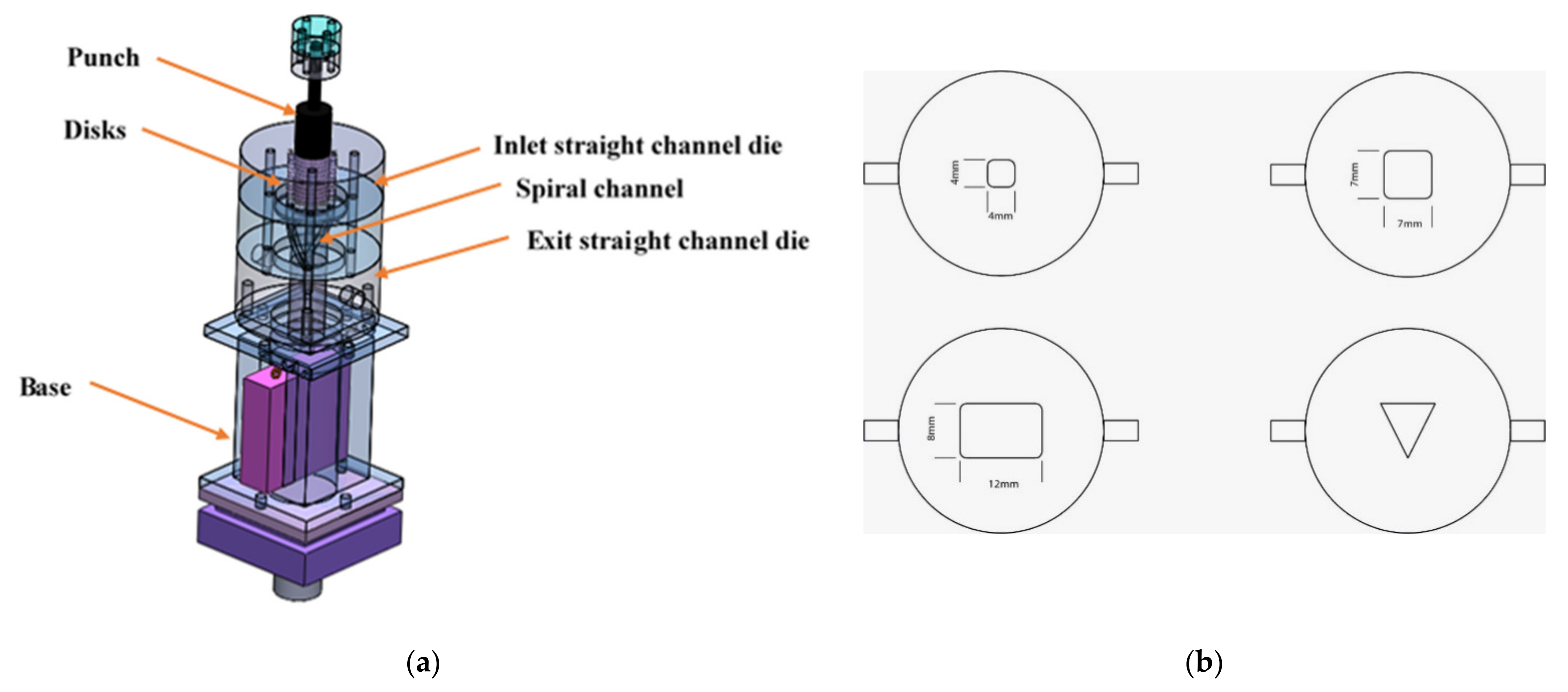
2. Materials and Methods

Strain hardenable AA5083-received in the form of 10 mm thick rolled plates-was processed via MCSTE in this study. The chemical composition of the alloy in wt% was 0.4% Fe, 4.5% Mg, 0.4% Mn and 0.1% Cu. Rectangular 10 mm × 10 mm × 40 mm billets were formed by sectioning using a wire-cut electrical discharge machining (EDM) machine followed by secondary machining. A further homogenization and softening treatment was applied, where the average grain size of 32 µm after annealing conducted at 400 °C for one hour with a subsequent air cooling.
Processing was performed using a 250 kN universal testing machine from Schenk Trebel (New York, NY, USA). All tests were conducted via route A (0 rotation between successive passes) at room temperature and a constant speed of 10 mm/min. The authors used this setup based on their study on MCSTE optimization [29], which provided that route A produced the maximum response. Furthermore, for purposes of comparison of the mechanical properties and structural evolution via MCSTE processing, two dies with twist angles of β 30° and 40° were utilized. The MCSTE novel die design features several advantageous aspects that are fully articulated in [19,27,30]. Several passes were executed until strain saturation, shear localization and failure occurred. Three passes were processed via MCSTE β 30° and 1-pass was processed via MCSTE β 40°. On the other hand, processing through MCSTE with β 40° via 2-passes at room temperature resulted in a shear localization and the fracture occurred as shown in Figure 2. For each pass, a layer of general-purpose graphite lubricant was applied to minimize friction in the disk/billet assembly and within the die walls. This was a crucial step in facilitating the processing and success of deformation. Additionally, a minimal backpressure was applied to intensify the strain hardening process. Figure 3 shows the AA5083 billets before and after MCSTE processing.
Furthermore, to assess the structural evolution post processing, the longitudinal (LS) and transverse (TS) cross-sections of the extrudates were sectioned by a high-precision Isomet cutter, where the former was parallel to the extrusion direction and the latter was perpendicular. Both cross-sections were prepared for hardness and structural evaluation by grinding and polishing. An HM112 hardness testing machine (Mitutoyo Co., Kawasaki, Japan) was used to record the Vickers microhardness values across an equidistant grid of 4 mm spacing along the peripheral region of the LS and a 1.25 mm spacing towards the center. Similarly, the TS was analyzed along the two diagonal lines of the cross-section with a 1 mm spacing between each recording. The tensile properties of the extrudates were investigated at room temperature using a universal testing machine with a capacity of 100 kN (MTS Systems Corporation, Eden Prairie, MN, USA) at a constant strain rate of 10−3 s−1. Tensile test samples were prepared from the extrudates’ centers according to E8M/ASTM standards with gauge a diameter of 6 mm. Two tensile samples were tested per condition.
For the electron backscatter diffraction (EBSD) investigation, the extrudates were sectioned through the mid-plane along the extrusion direction (ED). Specimens were prepared by grinding and polishing according to standard procedures. After mechanical polishing, the specimens were further electropolished in a 30 vol.% nitric acid and 70 vol.% ethanol solution for 60 s at a temperature of −15 °C and 15 V. A Quanta FEI 250 SEM (FEI company, Hillsboro, OR, USA) equipped with an EDAX-EBSD camera (EDAX Inc. Mahwah, NJ, USA) controlled by orientation image microscopy data collection software (OIM DC 7.3, EDAX Inc., Mahwah, NJ, USA) was used to investigate the grain structure and crystallographic texture of the prepared MCSTE extrudates. OIM data collection was carried out for a square area of 3000 µm × 3000 µm using a 10 µm step size for the as-annealed (AA) plate due to the presence of extremely coarse grains. A 4 µm step size in a square area of 1000 µm × 1000 µm was used to collect the OIM data for the AA plate and for the 1-, 2- and 3-passes MCSTE extrudates. All the data were collected at fixed conditions of 20 kV acceleration voltage and a working distance of 15 mm. Finally, the OIM data were processed using TSL OIM analysis 7.3 software (OIM DC 7.3, EDAX Inc. Mahwah, NJ, USA). The percentage of indexed points acquired in all maps were higher than 95% and the cleaning conducted using grain tolerance angle of 5° and the minimum grain size consist of 4 pixels. Both pole figures (PFs) and orientation distribution function (ODF) sections were calculated using harmonic series expansion with series rank of 16 and Gaussian half width of 5° with triclinic sample symmetry.

3. Results and Discussion

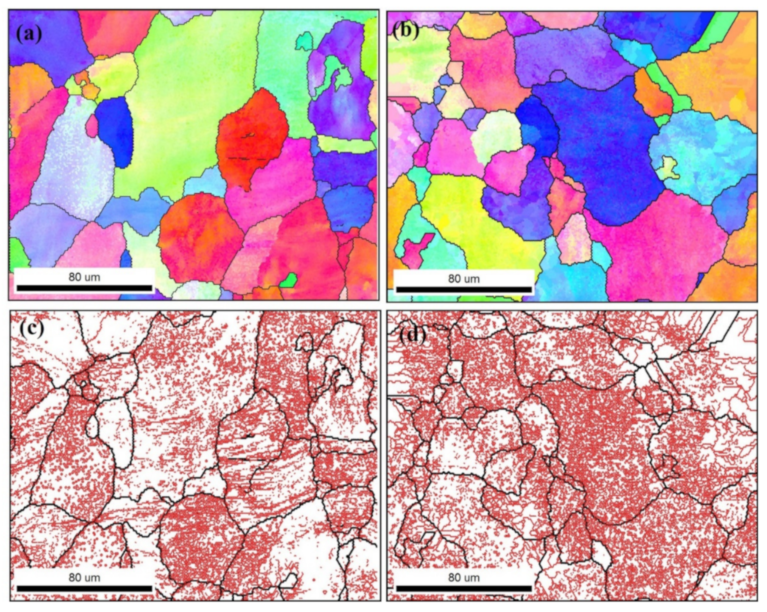
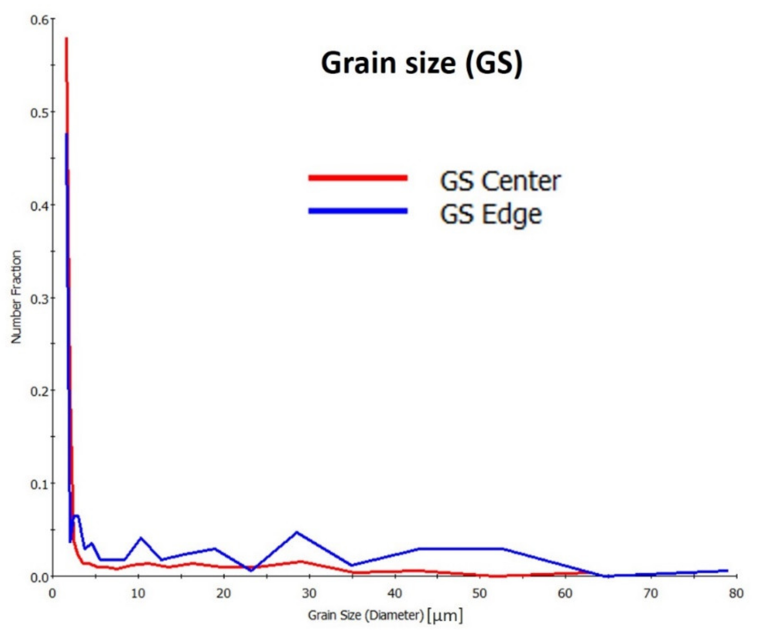
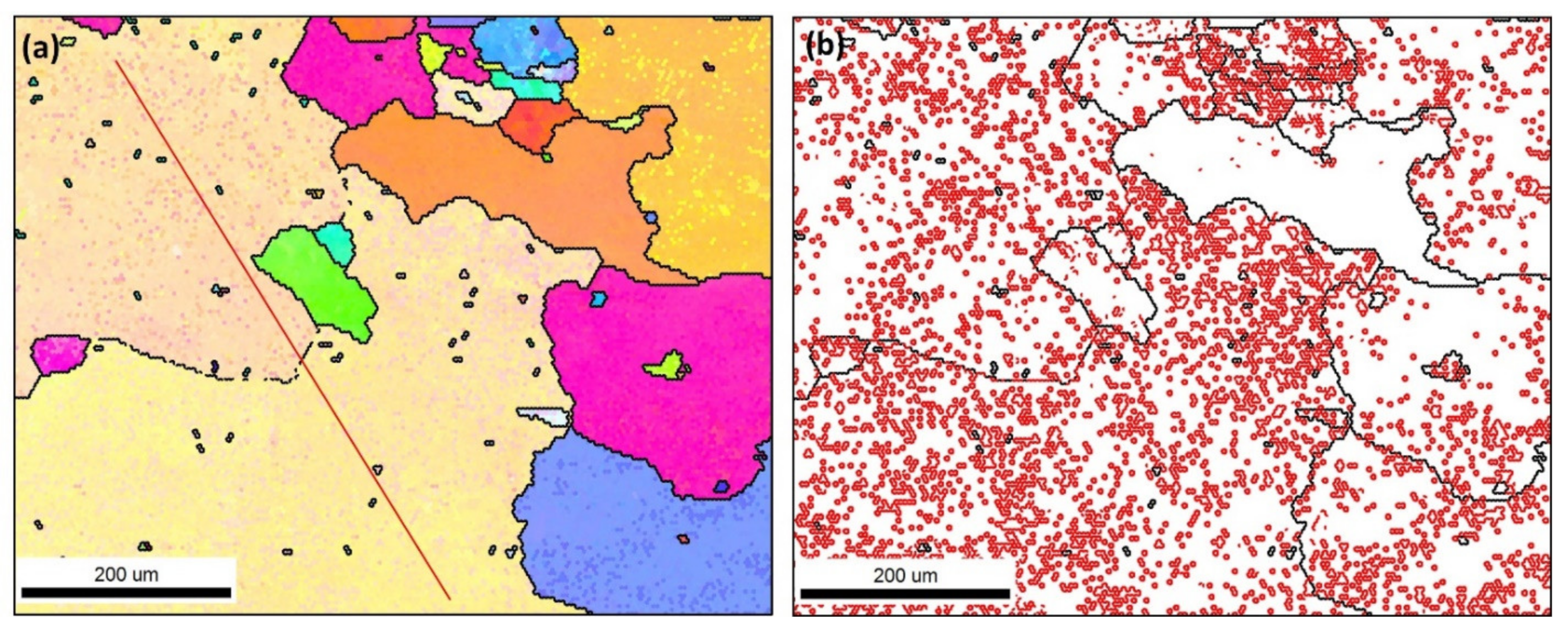
3.1. Grain Structure

EBSD characterization was conducted to investigate the grain structure of aluminum alloy AA5083 after multiple MCSTE passes and compared with that of the as-annealed (AA) plate. EBSD data were recorded at the edge and the center of the extrudates to examine the microstructure homogeneity across the mid-section perpendicular to the extrusion direction (ED). Figure 4 shows the inverse pole figure (IPF) coloring and the grain boundary maps of the AA sample acquired at 10 µm for a square area of 3 × 3 mm2. It can be observed that the microstructure mainly consists of irregularly shaped coarse grains (>1000 µm) that might be formed due to abnormal grain growth upon the annealing process. The grain boundary map is almost free from the low angle grain boundaries (LAGBs) due to the static recrystallization.
Furthermore, Figure 5 shows the IPF and grain boundary maps for the AA (a, b) and 1-pass MCSTE AA5083 extrudates (c, d). Both maps were acquired from similar respective square sectional areas for the purposes of comparison and at the same step size of 4 µm. Significant grain refinement can be observed after 1-pass MCSTE processing coupled with a high density of LAGBs, which indicates the severity of the deformation experienced during the 1-pass MCSTE processing. The average grain size was reduced from 200 µm to approximately 35 µm, which agrees with the results reported by the authors for AA1100 processed with MSCTE [22]. The significant grain refining observed after 1-pass with the new grains, almost full of LAGBs (substructure), implies that a dynamic recrystallization (DRX) process takes place during the MCSTE, which results in high-angle grain strcuture. DRX is classified as discontinuous DRX (DDRX) or continuous DRX (CDRX) [31,32]. DDRX occurs in cubic metals of low stacking fault energy in which new dislocation-free grains develop at sites such as original grain boundaries, deformation band interfaces or boundaries of newly recrystallized grains [32,33]. In CDRX, high-angle grain boundaries are formed during high-temperature deformation in ways other than the normal nucleation and growth of grains at the original grain boundaries [24]. CDRX may occur by the progressive rotation of the subgrains with little accompanying boundary migration, which is termed CDRX by progressive lattice rotation [31]. The second type of CDRX is known as geometric dynamic recrystallization (GDRX), in which the original grain boundaries develop serrations during dynamic recovery, and the wavelength of these serrations is similar to the subgrain size. If the material is subjected to a large reduction in cross-section, such as in hot rolling or hot compression, then the original grains become flattened, and a new grain structure is formed with grain size comparable to the subgrain size [31,32]. The microstructure obtained in this work using MSCTE suggests that CDRX occurs by progressive lattice rotation adjacent to the original grain boundaries. It has been reported that CDRX is an effective mechanism for grain refinement in aluminum alloys subjected to sever plastic deformation [34]. This occurs through the formation of geometrically necessary boundaries (GNBs) which results in 3D network of LAGBs followed by gradual transformation to high angle grain boundaries (HAGBs) [34]. This process slightly limited at room temperature however, it could operate at moderate temperatures generated during processing via MCSTE generated by friction. It has been reported that at room temperature, the ability of lattice dislocations to rearrange by climb or cross-slip is very limited and may occur only in the vicinity of deformation-induced boundaries [35]. The HAGBs developed at room temperature deformation can generally be characterized as GNBs. The evolution of these boundaries is associated with differences in the operating slip systems within individual regions of particular grains that result in subdivision of the grain into number of subgrain followed by evolution into grains. The various grains then experience different rotations during plastic deformation [35]. This might explain the observed microstructure after 1-pass that consists of new relatively fine grains that have a high density of LAGBs. Wu et al. [36] studied the effect of micro-sized Si particles and nano-sized dispersoids on the dynamic recrystallization of near-eutectic Al–Si based alloys during hot compression. They reported that the activation energy of the near-eutectic Al–Si alloy is greatly improved and dynamic recrystallization (DRX) is significantly inhibited at relatively high strain rate, due to micro alloying of Zr and V. They also reported that high temperature is beneficial for rotation and rearrangement of grain nuclei and subgrains, positively affecting DRX. Liu et al. [37] suggested two step dynamic recrystallization to get activated during ECAP deformation of Mg97Y2Zn1 alloy. In early passes of ECAP, DRX is promoted by 18R kinking through particle-stimulated nucleation (PSN) mechanism, and the precipitation of 14H lamellas suppresses DRX process in this period. After 14H lamellas became kinked, zigzagged and broken with more ECAP passes, the refined 14H accelerates the second step DRX process through PSN mechanism.
The homogeneity of the microstructure along the cross-section was investigated by acquiring EBSD maps using 1 µm step size at the edge and the center of the extrudates; the results are presented in Figure 6 as IPF and grain boundary maps. It can be observed that the grain structure and structure morphology are similar at the edge and center of the extrudate, indicating a high degree of straining uniformity imposed across the whole cross-section. The average size at the edge and the center is 38.4 µm with standard deviations of 13 µm and 38 µm with standard deviations of 20 µm, respectively.
Additionally, the distribution of grain size in terms of number fraction is illustrated in Figure 7, which shows a slightly higher number fraction of ultrafine grains at the center than at the edge. On the other hand, the number fraction of large grains of the HAGBs is higher at the edge than at the center as it can be observed from the chart starting from grain size about 5 µm up 60 µm the curve of the of grain size distribution for the edge data (blue curve) is higher than that for the center data (red curve). This might reflect a slightly higher rate of recrystallization at the edge than at the center of the sample.
Similarly, the grain structure was evaluated after 2-passes and 3-passes MCSTE processing of AA5083, and the IPF and grain boundary maps are presented in Figure 8 and Figure 9, respectively. Figure 8 shows the IPF and grain boundary maps at the edge (a, c) and the center (b, d). Grain coarsening can be observed after 2-passes and 3-passes processing in a similar behavior observed for the MCSTE processed AA1100 [30]. This coarsening after 2-passes and 3-passes can be attributed to the accumulation of stored energy of deformation that enables the continuous grain coarsening at edge of the sample in a rate faster than at the center. Nevertheless, in Figure 9, although there are some coarse grains, there are still a large number of very fine grains that can be observed within the high density of the LAGBs. Moreover, Figure 10 records the grain size distribution chart for the extrudates processed with 1-pass, 2-passes and 3-passes MCSTE compared to the AA condition. It can be clearly observed that the fraction of fine grains less than 20 µm increased as a result of increasing the number of passes to reach a reduction of approximately 65% after 3-passes processing.
The misorientation angle distribution chart is also presented for the AA, 1-pass, 2-passes and 3-passes MCSTE processing in Figure 11. It can be observed that the LAGBs fraction increased as a function of straining up to 2-passes with a slight reduction after 3-passes. This is associated with an increase in the fraction of HAGBs and fine grains recorded after 3-passes of MCSTE.
The misorientation profile is also obtained at the red lines indicated on the IPF maps (Figure 5, Figure 8 and Figure 9) and presented in Figure 12. This misorientation profile obtained along the red lines shown on the IPF maps indicates the presence of a high density of LAGBs observed after 2–passes and 3-passes of processing in comparison with the free LAGBs observed in the AA plate.
In terms of the crystallographic texture analysis, the 001, 101 and 111 pole figures (Figure 13) and the ODF sections at φ2 = 0° and φ2 = 45° (Figure 14) are calculated for the AA condition data presented in Figure 2 and the 1-pass MCSTE condition presented in Figure 5b. Data were specifically obtained from the aforementioned samples, as they were comprised of enough grains to represent the crystallographic texture of the materials. Both the PFs and the ODF section of the AA plate revealed a strong (eight times as random in PFs and 20 times as random in the ODFs) ideal rotated cube texture commonly associated with the annealing of heavily rolled aluminum. The texture after 1-pass MCSTE processing was slightly random (only twice as random in PFs and four times as random in ODFs) in texture, which could be due to the high density of intermetallic particles present in this alloy. It has been reported that AA5083 alloy contains intermetallic particles of types (Mn,Fe)Al7 and Mg2Si [38,39,40].

3.2. Mechanical Properties

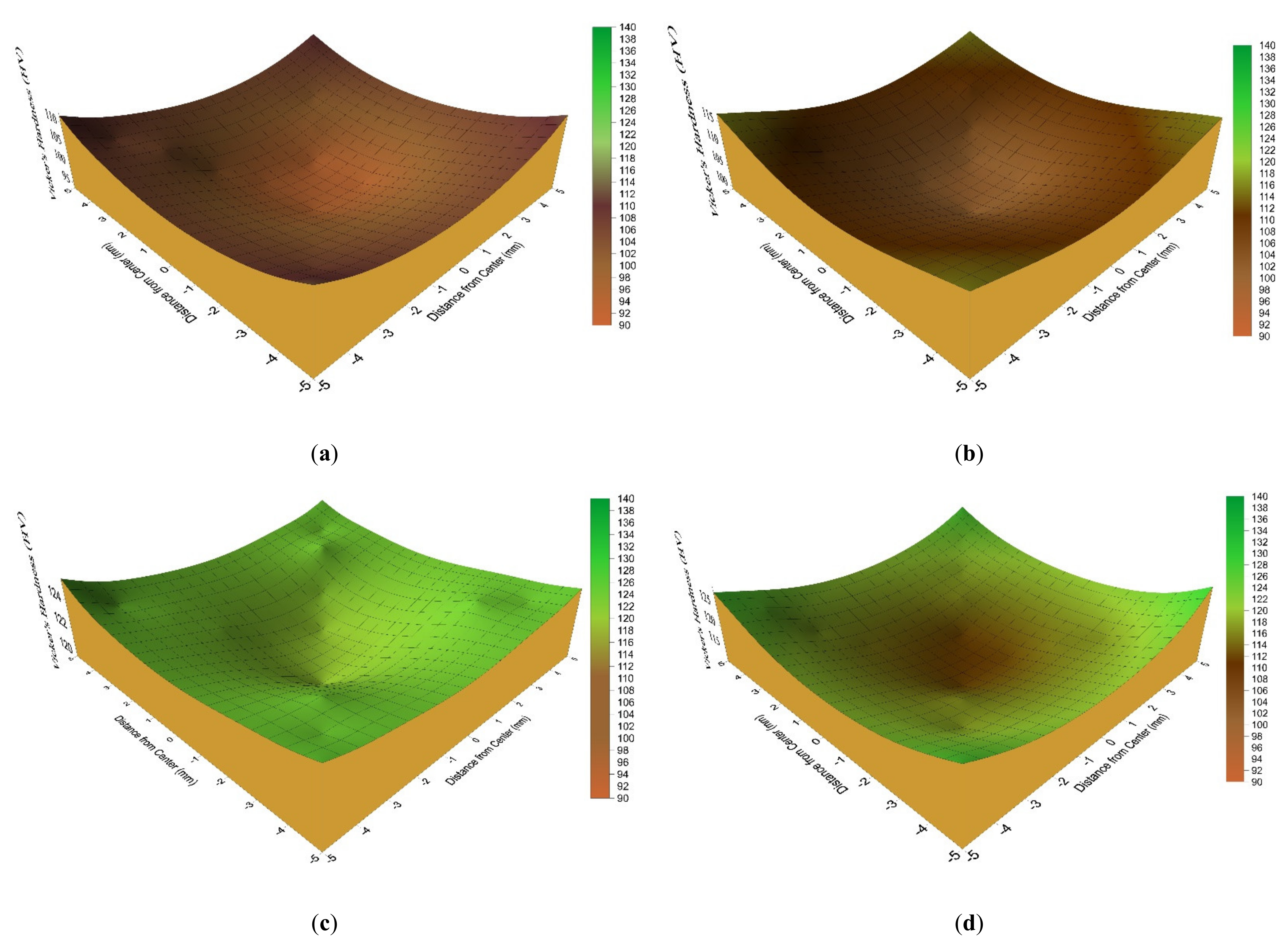
3.2.1. Microhardness Evolution

Figure 15 and Figure 16 depict the Vickers microhardness 3D-colored contours of the MCSTE AA5083 extrudates measured across LS and TS cross-sections, respectively. In addition, the Vicker’s hardness mean values recorded in the centeral and perpheral reigions of AA5083 samples are listed in Table 1. Figure 15 and Figure 16a–c show the microhardness evolution after MCSTE β 30° processing along the peripheral and central regions of the 1-pass, 2-passes, and 3-passes extrudates, respectively, and Figure 16d shows the evolution after 1-pass extrudate of MCSTE β 40° processing. The average microhardness of the AA billet is 80 Hv. From the displayed 3D-colored contours, it can be observed that a general increase in hardness occurs as a function of increasing number of passes. A gradual increase in hardness occurs along the peripheral and central regions of the 1-pass extrudate, as observed in Figure 15a, with the highest hardness values being recorded at the bottom segments along the periphery at 111.6 Hv compared to 97 Hv at the top segment. Similar observations were made after 2- and 3-passes MCSTE β 30° and 1-pass MCSTE β 40°, as shown in Figure 15b–d, respectively. This trend is illustrated by the strain distribution contours in [19], wherein higher hardness measurements coincide with higher strain values. Additionally, this observation is consistent with findings made by the authors in [30], where MCSTE processing of AA1100 led to an equivalent trend in hardness distribution. The authors explained that higher Hv values experienced at the bottom segments were due to the backpressure applied to the system which generated from the extension springs that connected to the pressing plunger, which imposed a resistance to the disk/billet assembly motion through the twist die [27]. It is worth to mentioning here that, the bottom part of the MCSTEed billets encounters a higher resistance to motion as a result of the backpressure springs which leads to increasing the hardness values of the bottom segment of the processed billets [27]. This resistance, although relatively small (5 MPa), induces an additional strain hardening effect that caused a short-range increase in the hardness at the bottom sections of the extrudates [30].
Additionally, Figure 15a,b show that the Hv values are constantly higher along the periphery and lower at the center. As demonstrated in Figure 15b for the 2-passes extrudate, the highest value recorded along the peripheral region is 114.6 Hv, whereas the lowest value of 98.7 Hv is recorded at the center. Similar findings were reported by the authors in [27,30], explaining that due to the nature of MCSTE, the highest friction is imposed at the disk-billet contact surfaces, which leads to a higher strain hardening effect compared to that at the center. The heterogeneous distribution of strain observed has been similarly reported for TE [19,30,41,42,43]. Figure 15c depicts a significant increase in hardness values as well as their distribution. After three processing passes, the Hv values at the center converge with those at the peripheral region, with the highest values recorded being 128 and 130 Hv, respectively. This increase is consistent with results reported after 4-passes of processing via a modified equal channel angular extrusion (ECAE) process [43]. An analogous pattern is also observed across the TS contours, as revealed in Figure 16c compared to Figure 16a,b. This is associated with the accumulation of strain and the subsequent homogenous multiplication of dislocations as a function of multiple-pass processing, which leads to hardness value proliferation and enhanced homogeneity across the MSCTE and TE extrudates [19,44,45]. Additionally, the increase of the recorded Hv values due to the increase in the imposed strain from increasing the number of passes is in good agreement with Figure 10. This behavior can be attributed to increasing the fraction of fine grains with increasing MCSTE processing passes.
Conversely, from the displayed contours in Figure 16a,b, it is evident that more strain hardening occurs at the corners compared to the central regions; the highest Hv values of 112 and 116 were reported at the corners versus the lowest values of 92.4 and 98.7 at the central regions of the 1-pass and 2-pass transverse section extrudates, respectively. This is consistent with the authors’ findings reported in [19], where it was demonstrated that the strain values were at their lowest in central regions in contrast with peripheral areas. This is attributed to the torsional nature of the MCSTE processes and based on TE [30]. Subsequently, the anisotropy improves after 3-passes (Figure 16c), with a maximum hardness of 125 Hv being recorded at the corner versus 119 Hv at the center. This corresponds with the increase in effective strain from 1 at the center to 1.7 at the corners after 3-passes of MCSTE (β 30°) processing [19].
Furthermore, the hardness contours depicted in Figure 15 and Figure 16d show a significant increase in hardness values after 1-pass processing via MCSTE (β 40°) along both the LS and TS. Similar trends in hardness distribution are depicted along the MCSTE (β 40°) extrudates but with a more significant increase; the Hv values reach 126 and 120 at the peripheral and central regions and 113 at the corner and central regions of the LS and TS, respectively. Evidently, the enhancement in hardness properties after only 1-pass (β 40°) is almost equivalent to that achieved after 3-passes of MSCTE processing with a lower twist angle (β 30°). Such proliferation is associated with the increase in the effective strain induced—for up to 0.9 per pass approaching that of conventional TE (β 60°) [29]. However, with reference to Figure 16d, it is markedly evident that 1-pass (β 40°) processing results in a greater variation in hardness distribution compared to its counterpart demonstrated in Figure 16c, showing that greater homogeneity is attained after 3-passes of MCSTE (β 30°). Similar conclusions were reported by the authors for AA1100 processed via MCSTE [46]

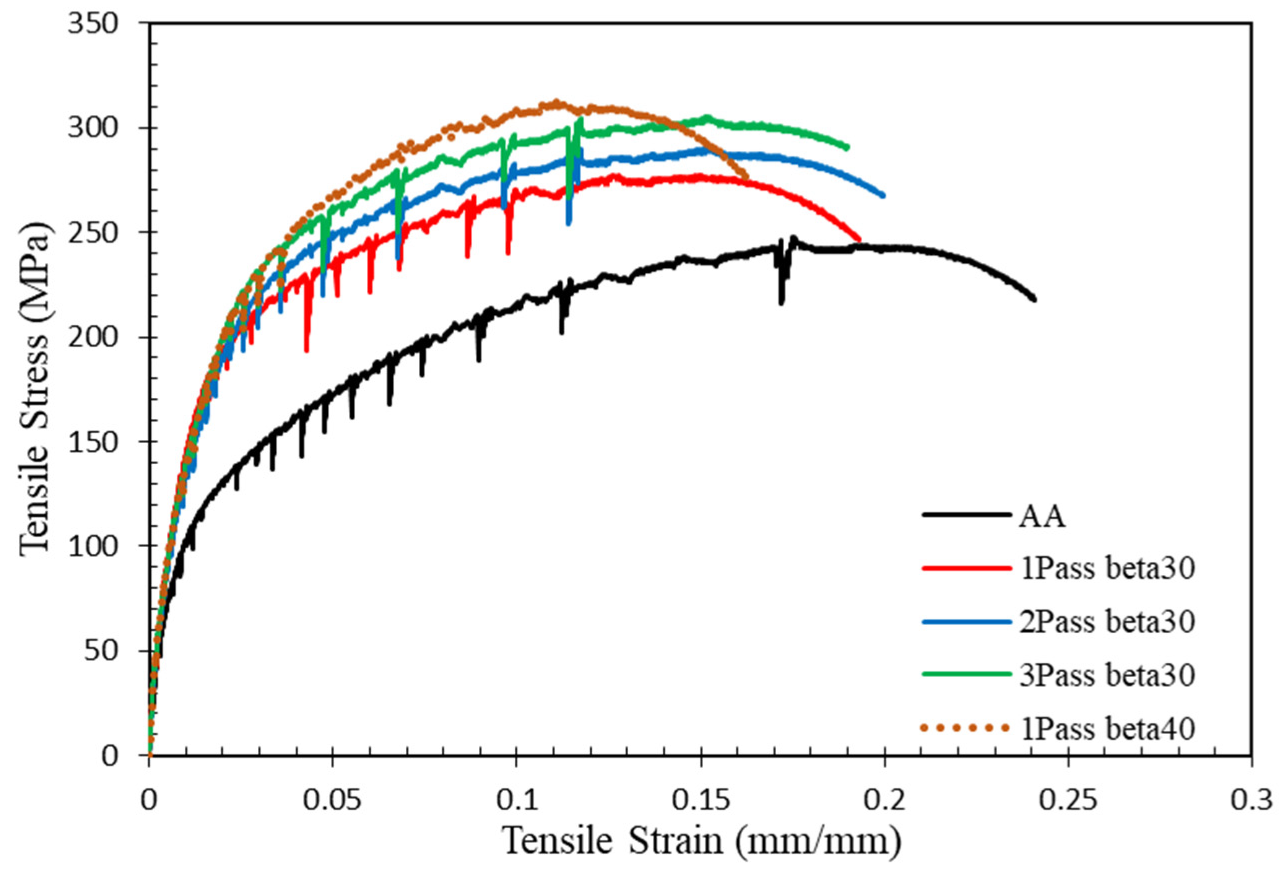
3.2.2. Tensile Properties

The stress-strain diagrams for AA5083 befor and after MCSTE processing are shown in Figure 17. In addition, Table 1 lists the yield strength (YS) variation alongside the ultimate tensile strength (UTS) and the elongation % of the various AA5083 alloys processed from 1 and up to 3-passes via MCSTE (β 30°) and of the alloy processed via 1-pass of MCSTE (β 40°) compared to the AA alloy plates. The displayed results reveal a trend of increased tensile strength with the increase of the number of MCSTE passes, compared to the AA condition. This can be attributed to the noticeable grain refinement with CDRX, which occurs with the increasing of the number of passes (as shown in Figure 3, Figure 6 and Figure 7 compared to Figure 2). As shown in Figure 17 and listed in Table 1, straining via 1-pass (β 30°) yields 111% and 9% increase in the YS and UTS, respectively, coupled with a 21% reduction in the ductility, compared to their AA counterpart.
This significant increase in YS is attributed to the significant decrease of grain size (from 200 μm to 20 μm) [19,30]. In addition, the generation and multiplication of dislocation during MCSTE processing as a result of cold working and their interaction together play an important role in strengthening the processed material which agreed with [27]. On the other hand, the UTS showed a slight improvement compared to the YS, which indicates that the 1-pass (β 30°) alloy’s uniform plastic deformation zone is mainly dominated by subgrains (LAGB), which do not contribute significantly to the strain hardening effect associated with dislocation pinning at the grain boundaries (as shown in Figure 5 and Figure 11), which agrees with the reported findings by EBSD analysis [19,47,48]. It is worth to mentioning here that, the slight increase of the UTS can be related to the strain hardening effect which resulted in the onset of necking soon after yielding and decreasing the nonuniform zone of the tensile curve which affected negatively the elongation of the processed AA5083 alloy which agreed with Iqbal et al. [49] and Skiba et al. [50]. In addition, the decrease in the elongation % of the 1-pass condition can be ascribed to the strain hardening of the metallic materials after yielding [19,51]. Strain accumlation in the 2-pass processed alloy results in an additional increase of 5.2% and 6.4% in the YS and UTS, coupled with an insignificant decrease in the ductility, compared to the 1-pass condition as shown in Table 1. The evolution of the tensile properties of AA5083 is expanded on in more detail in [19]. The increase in strength as a function of increasing the number of passes is in line with the increase in the fraction of fine grains and HAGBs depicted in Figure 11.
As shown in Figure 17, cumulative SPD using MSCTE up to 3- passes leads to a slight increase in the YS and UTS, which reaches 215 MPa and 300 MPa compared to the 200 MPa and 266 MPa after 2-passes, respectively, coupled with an insignificant reduction in elongation (~5%). These slight improvements in mechanical properties occur despite the notable decrease in grain size after 3-passes, as evident from the values measured after 2-passes of processing (Figure 8 and Figure 9). Accordingly, processing through 3-passes of MCSTE increases the percentage of fine grains up to 65%; this refinement, in conjunction with the increase in the imposed strain, is a function of increasing the number of passes as found in [19]. The increasing rate of grain size refinement during successive imposed passes is suggested to be caused by the presence of second-phase, particles as suggested in [5].
These second-phase particles reduce the alloy stacking fault energy (SFE) and its tendency for dynamic recovery, thus producing finer grains [1,12]. On the other hand, although the UTS significantly increases as a result of strain accumulation up to 3-passes, AA5083 processed samples show an insignificant reduction in the ductility, which can be attributed to the occurrence of dynamic recovery, which results in the annihilation of dislocations during further MCSTE processing and hence enables the MCSTEed samples to accommodate further deformation, all of which agree with previous studies [52,53]. Processing via 1-pass of MCSTE β (40º) results in a 21% and a 26% increase in YS and UTS, respectively, coupled with a 19% reduction in the elongation compared to the 1-pass processed samples using MCSTE β (30º) as shown in Figure 17. This demonstrates the increased intensity of strain hardening caused by higher angles of twist. Finally, increasing the number of passes above 1-pass using a twisting angle β (40º) results in severe shear localization at room temperature. The aforementioned improvement in the mechanical properties and hardness values of the MCSTEed samples can be explained by the increase in dislocation density and the development of a fine subgrain structure due to the high accumulative strain imposed on the SPD processed samples [10,54,55]. Accordingly, the grain refinement obtained from MCSTE processing leads to the formation of new grain boundaries and hindering the dislocations’ motion and thus enhances the mechanical properties of the AA5083 alloy.

4. Conclusions

In this study, EBSD evaluation was conducted to analyze the grain structure evolution associated with processing AA5083 via MCSTE. The findings reveal that:
1)
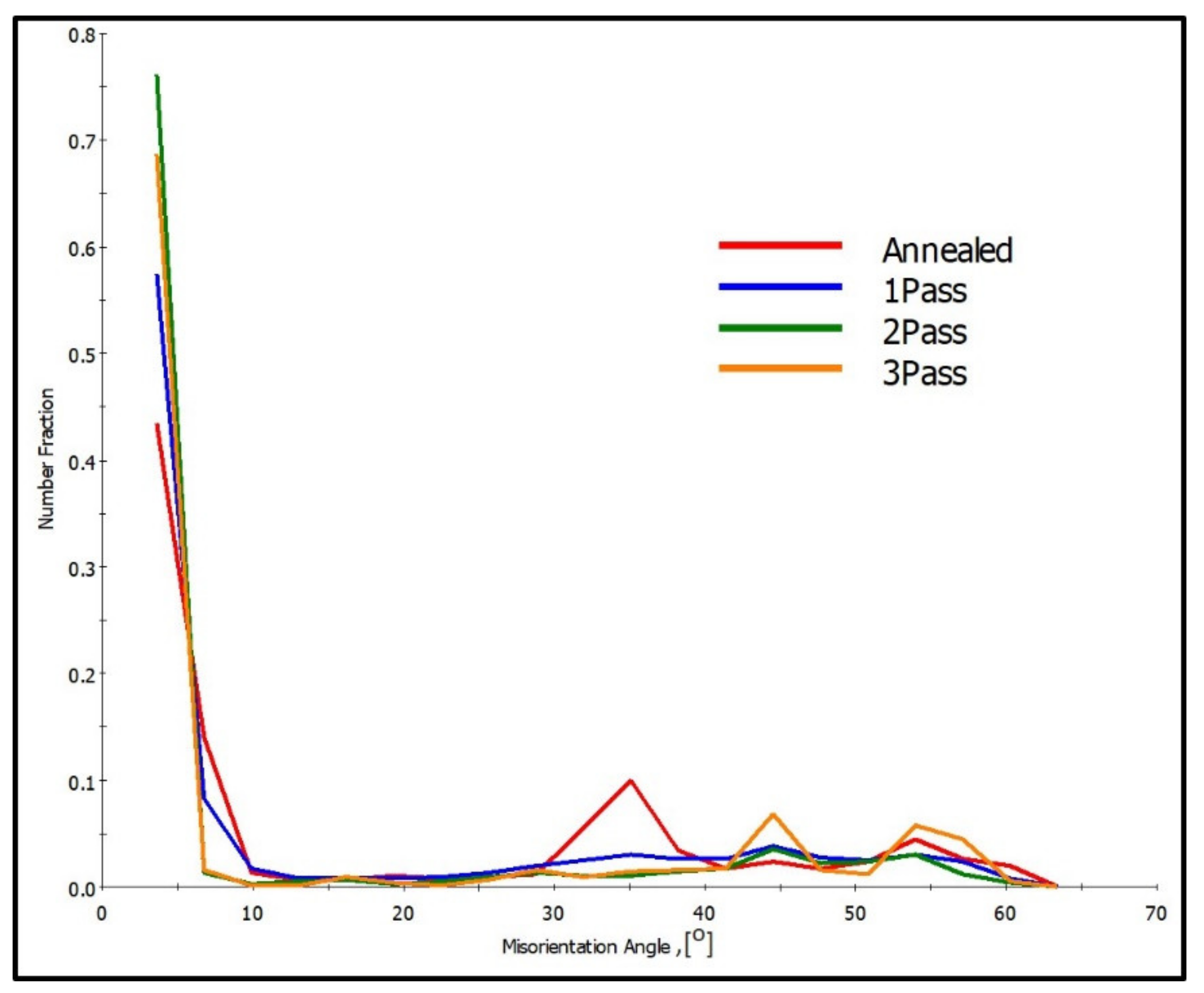
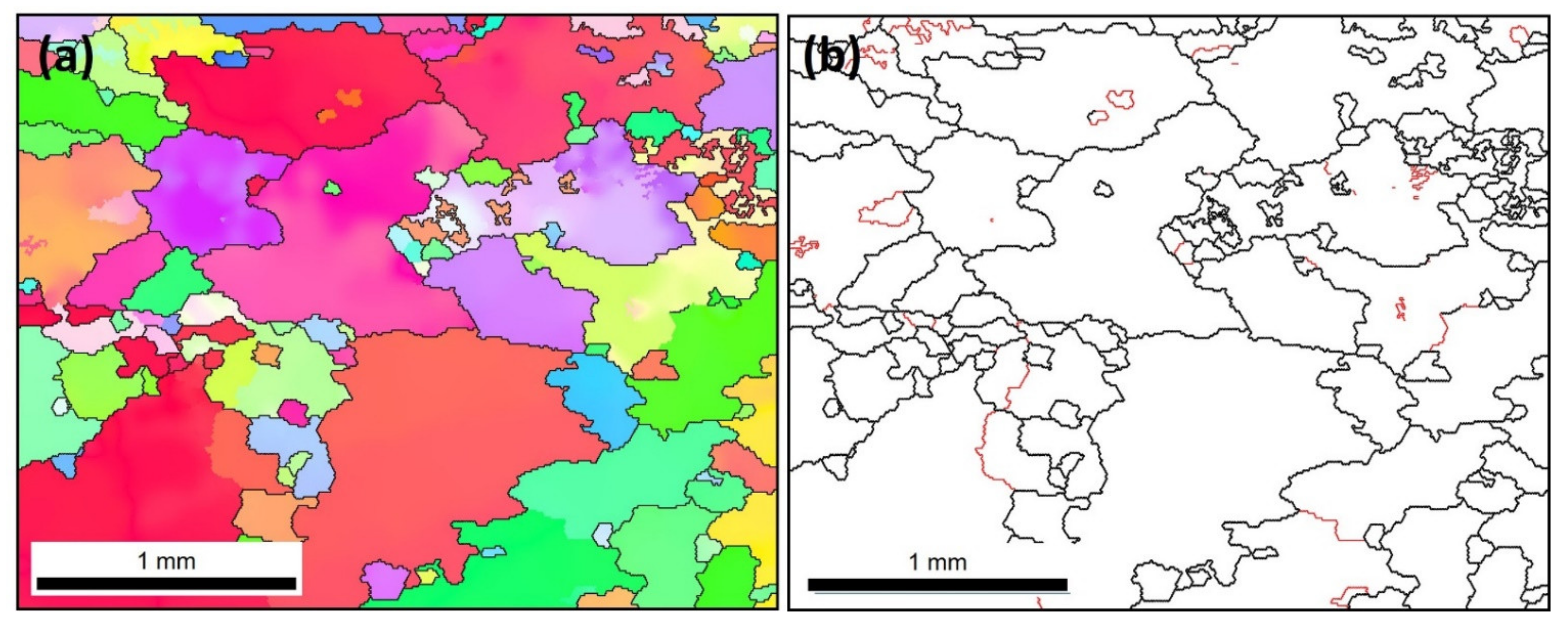
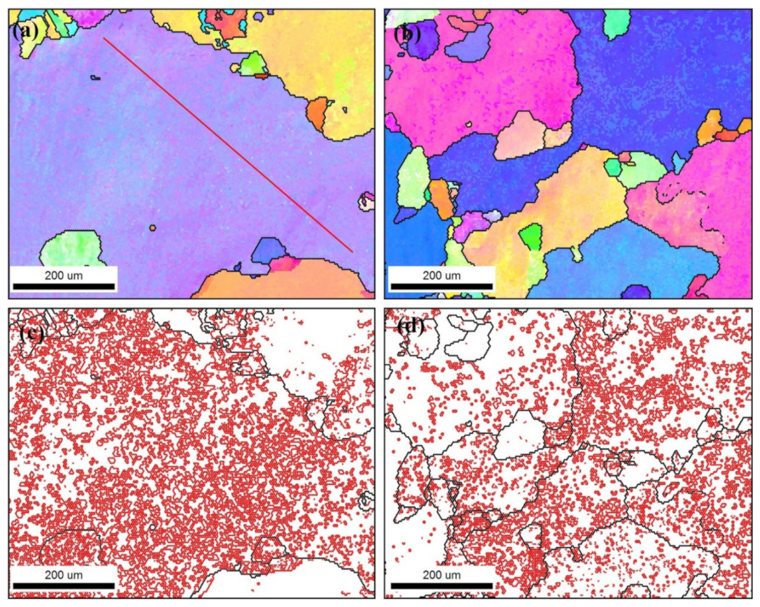
A significant grain refinement is achieved after MCSTE processing coupled with an increase in HAGBs as a function of increasing the number of passes.
2)
MSCTE using twist angle of β = 30° results in 65% grain refinement after 3-passes, reaching 20 μm compared to 200 μm in the AA condition.
3)
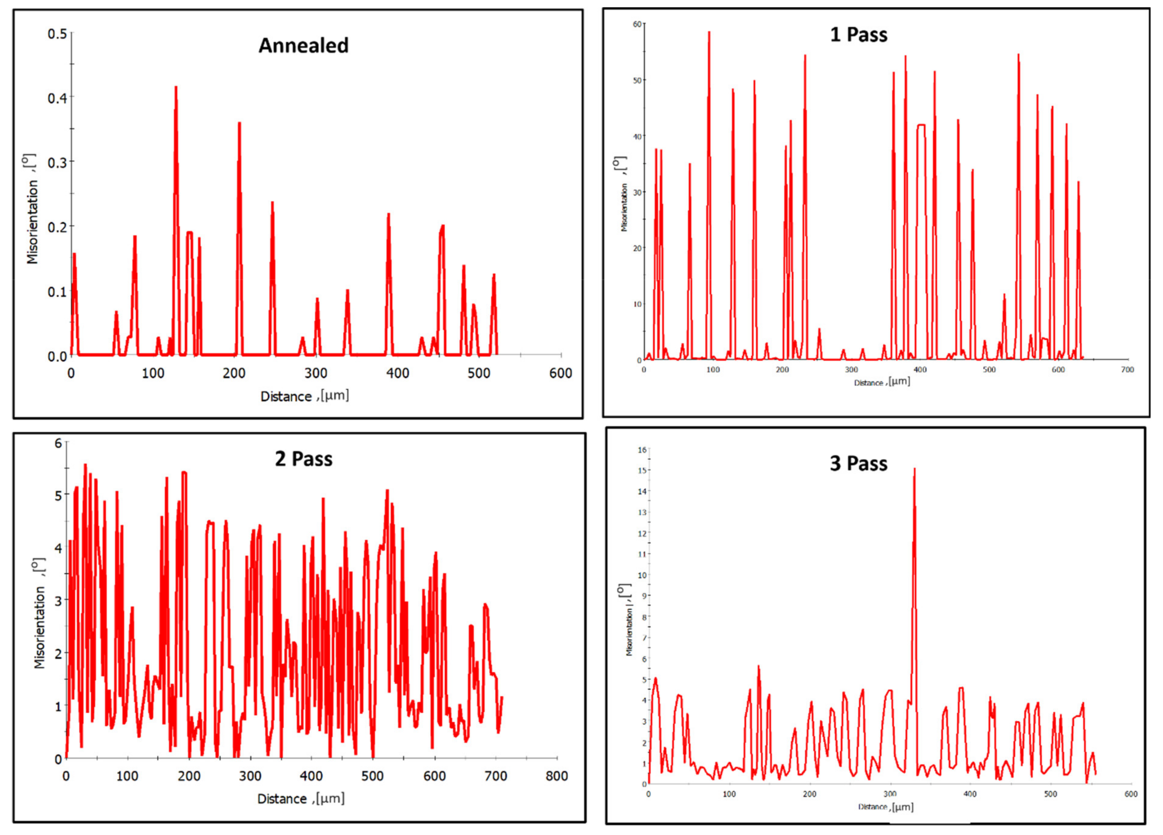
Misorientation profile maps reveals an increase in the fraction of LAGBs after 2-passes compared to the AA condition followed by an increase in the HAGBs after 3-passes.
4)
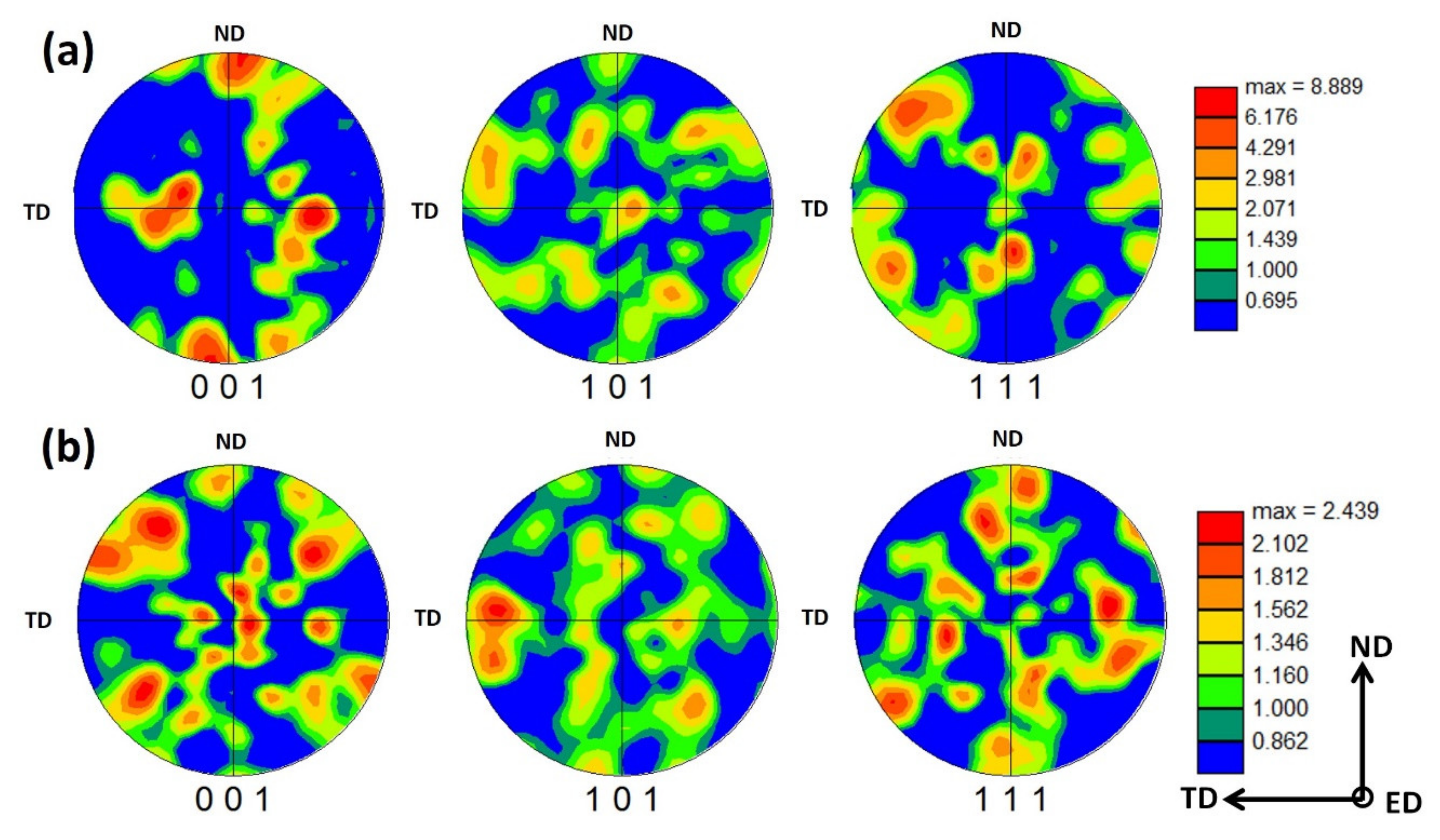
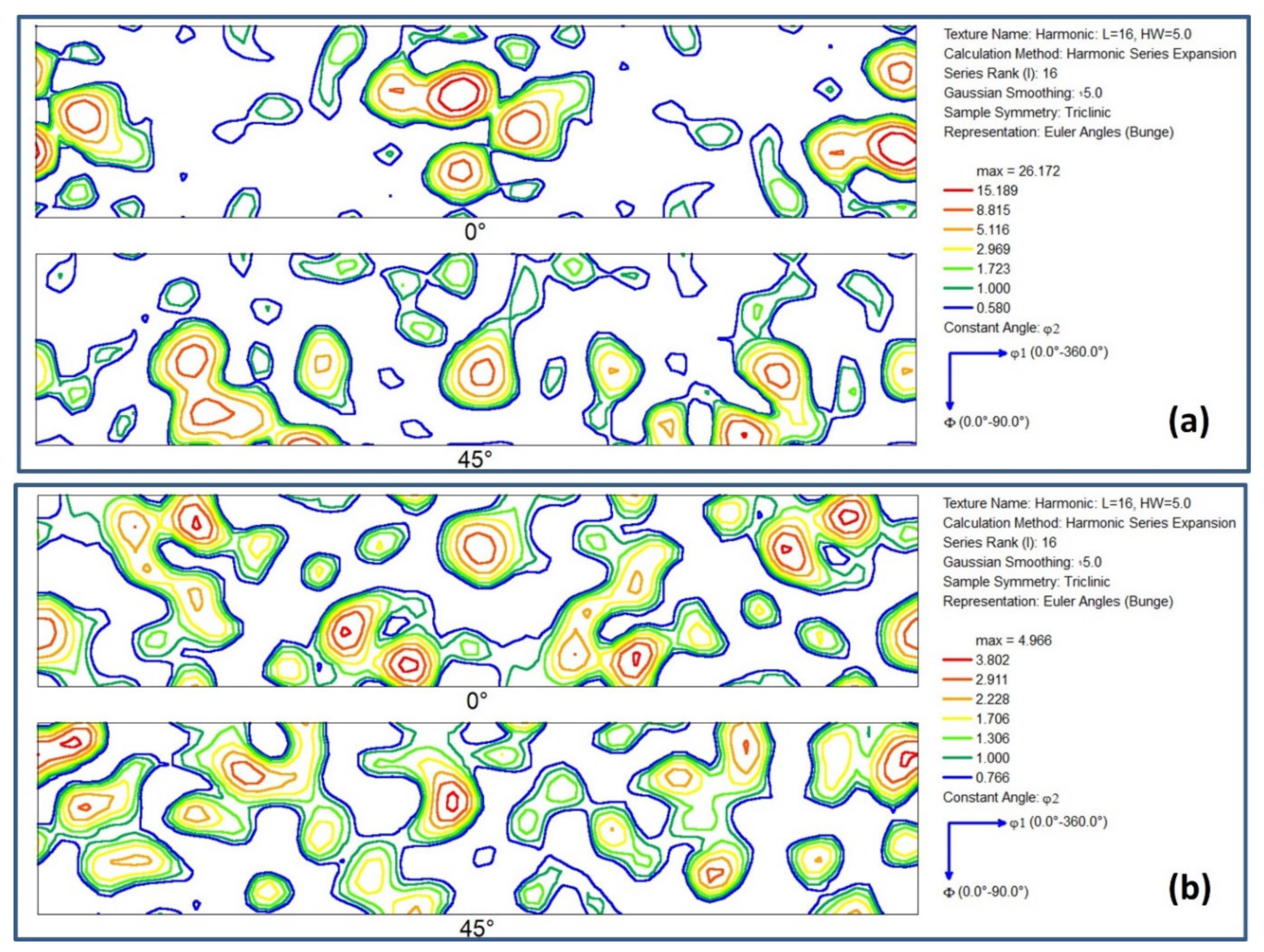
The crystallographic texture analysis depicted the formation of a cubic texture for the AA plate and demonstrates a random texture for 1-pass extrudate.
5)
The hardness and tensile strength increased with increasing number of passes due to the significant grain size reduction and the evolution of subgrains (LAGB) into grains with increasing the intensity of deformation from one-to-three passes via MSCTE.
6)
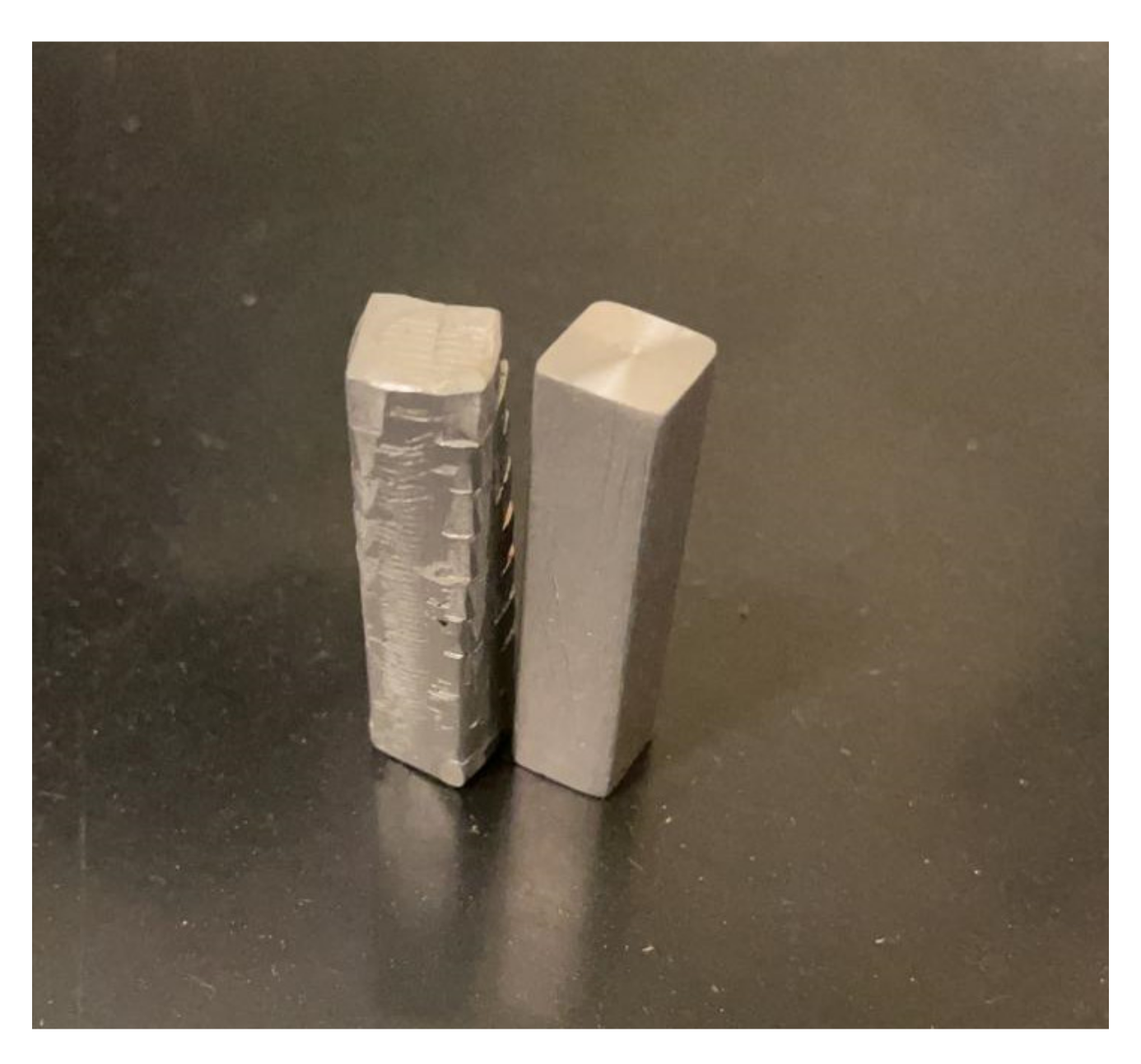
MSCTE processing via twisting angle β (40°) results in a high intensity of deformation, leading to strain saturation and shear localization after 1-pass of MCSTE.
7)
Homogenization of the microstructure and hence hardness distribution is achieved post 3-passes processing via twist angle β (30°) and only one pass processing via twist.

Author Contributions

Conceptualization, W.H.E.-G. and H.G.S.; methodology, D.M.F.; W.H.E.-G.; H.G.S. and M.M.E.-S.S.; validation, D.M.F.; W.H.E.-G.; M.M.Z.A.; I.A.; M.M.E.-S.S. and H.G.S.; formal analysis, D.M.F.; W.H.E.-G.; M.M.Z.A. and H.G.S.; investigation, D.M.F.; W.H.E.-G.; M.M.Z.A.; I.A.; M.M.E.-S.S. and H.G.S.; data curation, D.M.F.; W.H.E.-G.; M.M.Z.A. and H.G.S.; writing—original draft preparation, D.M.F.; M.M.Z.A.; writing—review and editing, D.M.F.; W.H.E.-G.; M.M.Z.A. and H.G.S.; visualization, D.M.F.; supervision, W.H.E.-G. and H.G.S.; project administration, H.G.S.; funding acquisition, I.A. All authors have read and agreed to the published version of the manuscript.

Funding

This research received no external funding.

Institutional Review Board Statement

Not applicable.

Informed Consent Statement

Not applicable.

Data Availability Statement

All the raw data supporting the conclusion of this paper were provided by the authors.

Acknowledgments

The authors of the work would like to acknowledge the Material Testing Laboratories at the Mechanical Engineering Department, AUC, and the YJ Science and Technology Research Center, AUC, for facilitating the use of the processing and testing equipment.

Conflicts of Interest

The authors declare no conflict of interest.

References

  1. Shen, J.; Chen, X.; Hammond, V.; Kecskes, L.; Mathaudhu, S.; Kondoh, K.; Wei, Q. The effect of rolling on the microstructure and compression behavior of AA5083 subjected to large-scale ECAE. J. Alloys Compd. 2017, 695, 3589–3597. [Google Scholar] [CrossRef]
  2. Cao, Y.; Ni, S.; Liao, X.; Song, M.; Zhu, Y. Structural evolutions of metallic materials processed by severe plastic deformation. Mat. Sci. Eng. R Rep. 2018, 133, 1–59. [Google Scholar] [CrossRef]
  3. Nouri, M.; Semnani, H.M.; Emadoddin, E.; Kim, H.K. Investigation of direct extrusion channel effects on twist extrusion using experimental and finite element analysis. Measurement 2018, 127, 115–123. [Google Scholar] [CrossRef]
  4. El-Shenawy, M.; Ahmed, M.M.Z.; Nassef, A.; El-Hadek, M.; Alzahrani, B.; Zedan, Y.; El-Garaihy, W.H. Effect of ECAP on the Plastic Strain Homogeneity, Microstructural Evolution, Crystallographic Texture and Mechanical Properties of AA2xxx Aluminum Alloy. Metals 2021, 11, 938. [Google Scholar] [CrossRef]
  5. Alateyah, A.; Aljohani, T.A.; Alawad, M.O.; El-Hafez, H.A.; Almutairi, A.N.; Alharbi, E.S.; Alhamada, R.; El-Garaihy, B.W.; El-Garaihy, W.H. Improved Corrosion Behavior of AZ31 Alloy through ECAP Processing. Metals 2021, 11, 363. [Google Scholar] [CrossRef]
  6. Alateyah, A.I.; Ahmed, M.M.Z.; Zedan, Y.; El-Hafez, H.A.; Alawad, M.O.; El-Garaihy, W.H. Experimental and Numerical Investigation of the ECAP Processed Copper: Microstructural Evolution, Crystallographic Texture and Hardness Homogeneity. Metals 2021, 11, 607. [Google Scholar] [CrossRef]
  7. Alateyah, A.I.; Alharbi, M.; Abd El-Hafez, H.M.; El-Garaihy, W.H. The Effect of Equal-Channel Angular Pressing Processing on Microstructural Evolution, Hardness Homogeneity, and Mechanical Properties of Pure Aluminum. SAE Int. J. Mater. Manuf. 2021, 14, 1–14. [Google Scholar]
  8. Almenaif, O.; Alhumaydan, Y.; Alnafisah, M.; Aldhalaan, M.; Alateyah, A.I.; El-Garaihy, W.H. A Computational Investigation into the Effect of Equal Channel Angular Processing on the Mechanical Properties of Severely Deformed ZK 60 Alloy Validated by Experiments. Am. J. Appl. Sci. 2020, 13, 296–310. [Google Scholar] [CrossRef]
  9. El-Garaihy, W.H.; Rassoul, E.S.M.A.; Salem, H.G. Consolidation of High Performance AA6061 and AA6061-SiCp Composite Processed by High Pressure Torsion. Mater. Sci. Forum. 2014, 783–786, 2623–2628. [Google Scholar] [CrossRef]
  10. Salem, H.G.; El-Garaihy, W.H.; Rassoul, E.-S.M.A. Influence of High Pressure Torsion on the Consolidation Behavior and Mechanical Properties of AA6061-SiCp Composites Powders. In Supplemented Proceeding: Materials Processing and Interfaces; The Minerals, Metals & Materials Society (TMS): Pittsburgh, PA, USA, 2012; Volume 1, pp. 553–560. [Google Scholar]
  11. Nassef, A.; Samy, S.; El-Garaihy, W.H. Enhancement of mechanical properties for Al-Mg-Si alloy using equal channel angular pressing. Int. J. Chem. Nucl. Mater. Metall. Eng. 2015, 9, 131–136. [Google Scholar]
  12. Ahmed, M.M.Z.; Seleman, M.M.E.; Zidan, Z.A.; Ramadan, R.M.; Ataya, S.; Alsaleh, N.A. Microstructure and Mechanical Properties of Dissimilar Friction Stir Welded AA2024-T4/AA7075-T6 T-Butt Joints. Metals 2021, 11, 128. [Google Scholar] [CrossRef]
  13. Ahmed, M.M.Z.; Ataya, S.; Seleman, M.M.E.; Allam, T. Grain Structure, Crystallographic Texture, and Hardening Behavior of Dissimilar Friction Stir Welded AA5083-O and AA5754-H14. Metals 2021, 11, 181. [Google Scholar] [CrossRef]
  14. Ahmed, M.M.Z.; Wynne, B.P.; Rainforth, W.M.; Addison, A.; Martin, J.P.; Threadgill, P.L. Effect of Tool Geometry and Heat Input on the Hardness, Grain Structure, and Crystallographic Texture of Thick-Section Friction Stir-Welded Aluminium. Metall. Mater. Trans. A 2019, 50, 271–284. [Google Scholar] [CrossRef]
  15. Singh, S.; Pal, K. Influence of Texture Evolution on Mechanical and Damping Properties of SiC/Li2ZrO3/Al Composite through Friction Stir Processing. J. Eng. Mater. Technol. 2020, 142, 021011. [Google Scholar] [CrossRef]
  16. Orlov, D.; Beygelzimer, Y.; Synkov, S.; Varyukhin, V.; Horita, Z. Evolution of microstructure and hardness in pure al by twist extrusion. Mater. Trans. 2008, 49, 2–6. [Google Scholar] [CrossRef]
  17. Stolyarov, V.V.; Lapovok, R. Effect of backpressure on structure and properties of AA5083 alloy processed by ECAP. J. Alloys Compd. 2004, 378, 233–236. [Google Scholar] [CrossRef]
  18. Rogachev, S.; Naumova, E.; Vasileva, E.; Magurina, M.Y.; Sundeev, R.; Veligzhanin, A. Structure and mechanical properties of Al–Ca alloys processed by severe plastic deformation. Mater. Sci. Eng. A 2019, 767, 138410. [Google Scholar] [CrossRef]
  19. Fouad, D.; Moataz, A.; El-Garaihy, W.H.; Salem, H.G. Numerical and experimental analysis of multi-channel spiral twist extrusion processing of AA5083. Mat. Sci. Eng. A 2019, 764, 138216. [Google Scholar] [CrossRef]
  20. Jin, H.; Gallerneault, M.; Segal, V.M.; Young, P.J.; Lloyd, D.J. Grain structure and texture in aluminum alloy AA5083 after equal angular channel extrusion, warm rolling and subsequent annealing. Mater. Sci. Technol. 2011, 27, 789–792. [Google Scholar] [CrossRef]
  21. Beygelzimer, Y.; Kulagin, R.; Estrin, Y.; Toth, L.S.; Kim, H.S.; Latypov, M.I. Twist Extrusion as a Potent Tool for Obtaining Advanced Engineering Materials: A Review. Adv. Eng. Mater. 2017, 19, 1600873. [Google Scholar] [CrossRef]
  22. Kunčická, L.; Kocich, R.; Ryukhtin, V.; Cullen, J.C.; Lavery, N.P. Study of structure of naturally aged aluminum after twist channel angular pressing. Mater. Charact. 2019, 152, 94–100. [Google Scholar] [CrossRef] [Green Version]
  23. Joudaki, J.; Safari, M.; Alhosseini, S.M. Twist Extrusion: Introduction, Strain Distribution, and Process Parameters Investigation. Met. Mater. Int. 2019, 25, 15931602. [Google Scholar] [CrossRef]
  24. She, J.; Peng, P.; Tang, A.T.; Zhang, J.Y.; Mao, J.J.; Liu, T.T.; Zhou, S.B.; Wang, Y.; Pan, F.S. Novel on-line twist extrusion process for bulk magnesium alloys. Mater. Des. 2019, 182, 108011. [Google Scholar] [CrossRef]
  25. Pardis, N.; Ebrahimi, R. Deformation behavior in simple shear Extrusion (SSE) as a new severe plastic deformation technique. Mater. Sci. Eng. A. 2009, 527, 335–360. [Google Scholar] [CrossRef]
  26. Orlov, D.; Beygelzimer, Y.; Synkov, S.; Varyukhin, V.; Tsuji, N.; Horita, N. Plastic flow, structure and mechanical properties in pure Al deformed by twist extrusion. Mater. Sci. Eng. A 2019, 519, 105–111. [Google Scholar] [CrossRef]
  27. El-Garaihy, W.H.; Fouad, D.M.; Salem, H.G. Multi-channel Spiral Twist Extrusion (MCSTE): A Novel Severe Plastic Deformation Technique for Grain Refinement. Metall. Mater. Trans. A 2018, 49, 2854–2864. [Google Scholar] [CrossRef]
  28. Gudimetla, K.; Jampana, G.V.; Kumar, S.R.; Ravisankar, B.; Kumaran, S. Effect of Equal Channel Angular Pressing on Densification Behavior of Al 5083 Alloy Powder. Mater. Sci. Forum 2015, 830–831, 63–66. [Google Scholar] [CrossRef]
  29. Latypov, M.I.; Yoon, E.Y.; Lee, D.J.; Kulagin, R.; Beygelzimer, Y.; Salehi, M.S.; Kim, H.S. Microstructure and Mechanical Properties of Copper Processed by Twist Extrusion with a Reduced Twist-Line Slope. Metall. Mater. Trans. A 2014, 45, 2232–2241. [Google Scholar] [CrossRef] [Green Version]
  30. Fouad, D.M.; El-Garaihy, W.H.; Ahmed, M.M.Z.; El-Sayed Seleman, M.M.; Salem, H.G. Influence of multi-channel spiral twist extrusion (MCSTE) processing on structural evolution, crystallographic texture and mechanical properties of AA1100. Mater. Sci. Eng. A 2018, 737, 166–175. [Google Scholar] [CrossRef]
  31. Ahmed, M.M.Z.; Wynne, B.P.; El-Sayed Seleman, M.M.; Rainforth, W.M. A comparison of crystallographic texture and grain structure development in aluminum generated by friction stir welding and high strain torsion. Mater. Des. 2016, 103, 259–267. [Google Scholar] [CrossRef]
  32. Humphreys, F.J.; Hatherly, M. (Eds.) Recrystallization and Related Annealing Phenomena; Elsevier Pergamon: Oxford, UK, 2004; pp. 1–658. [Google Scholar]
  33. Mcnelley, T.R.; Swaminathan, S.; Su, J.Q. Recrystallization Mechanisms during Friction Stir Welding/Processing of Aluminum Alloys. Scr. Mater. 2008, 58, 349–354. [Google Scholar] [CrossRef] [Green Version]
  34. Kaibyshev, R.; Malopheyev, S. Mechanisms of dynamic recrystallization in aluminum alloys. Mater. Sci. Forum 2014, 794–796, 784–789. [Google Scholar] [CrossRef]
  35. Sakai, T.; Belyakov, A.; Kaibyshev, R.; Miura, H.; Jonas, J.J. Dynamic and post-dynamic recrystallization under hot, cold and severe plastic deformation conditions. Prog. Mater. Sci. 2014, 60, 130–207. [Google Scholar] [CrossRef] [Green Version]
  36. Wu, Y.; Liu, C.; Liao, H.; Jiang, J.; Ma, A. Joint effect of micro-sized Si particles and nano-sized dispersoids on the flow behavior and dynamic recrystallization of near-eutectic Al–Si based alloys during hot compression. J. Alloys Compd. 2021, 856, 158072. [Google Scholar] [CrossRef]
  37. Liu, H.; Ju, J.; Yang, X.; Yan, J.; Song, D.; Jiang, J.; Ma, A. A two-step dynamic recrystallization induced by LPSO phases and its impact on mechanical property of severe plastic deformation processed Mg97Y2Zn1 alloy. J. Alloys Compd. 2017, 704, 509–517. [Google Scholar] [CrossRef]
  38. Yasakau, K.A.; Zheludkevich, M.L.; Lamaka, S.V.; Ferreira, M.G.S. Role of intermetallic phases in localized corrosion of AA5083. Electrochim. Acta 2007, 52, 7651–7659. [Google Scholar] [CrossRef]
  39. Czechowski, M. Low-cycle fatigue of friction stir welded Al–Mg alloys. J. Mater. Process. Technol. 2005, 164–165, 1001–1006. [Google Scholar] [CrossRef]
  40. Lucadamo, G.; Yang, N.Y.C.; Marchi, C.S.; Lavernia, E.J. Microstructure characterization in cryomilled Al 5083. Mater. Sci. Eng. A 2006, 430, 230–241. [Google Scholar] [CrossRef]
  41. Zendehdel, D.H.; Hassani, A. Influence of twist extrusion process on microstructure and mechanical properties of 6063 aluminum alloy. Mater. Des. 2011, 37, 13–18. [Google Scholar] [CrossRef]
  42. Bakkar, A.; Ahmed, M.M.Z.; Alsaleh, N.A.; Seleman, M.M.E.; Ataya, S. Microstructure, Wear, and Corrosion Characterization of High TiC Content Inconel 625 Matrix Composites. J. Mater. Res. Technol. 2019, 8, 1102–1110. [Google Scholar] [CrossRef]
  43. Iqbal, U.M.; Kumar, V.S. An analysis on effect of multi-pass twist extrusion process of AA6061 alloy. Mater. Des. 2013, 50, 946–953. [Google Scholar] [CrossRef]
  44. Faregh, S.S.; Hassani, A. Stress and strain distribution in twist extrusion of AA606 aluminum alloy. Int. J. Mater. Form. 2018, 11, 175–184. [Google Scholar] [CrossRef]
  45. Kalahroudi, F.J.; Eivani, A.R.; Jafarian, H.R.; Amouri, A.; Gholizadeh, R. Inhomogeneity in strain, microstructure and mechanical properties of AA1050 alloy during twist extrusion. Mater. Sci. Eng. A 2016, 667, 349–357. [Google Scholar] [CrossRef]
  46. Fouad, D.M.; Moataz, A.; El-Garaihy, W.H.; Salem, H.G. Multi-objective Optimization of Multi-Channel Spiral Twist Extrusion Process Using a Response Surface Approach and Finite Element Analysis. In Proceedings of the Materials Science & Technology Conference & Exhibition Proceeding (MS &T 2018), Columbus, OH, USA, 14–18 October 2018; pp. 1470–1477. [Google Scholar]
  47. Beygelzimer, Y.; Kulagin, R.; Davydenko, O. Vortex Formation Under Twist Extrusion. Nanosyst. Nanomater. Nanotechnol. 2016, 14, 553–560. [Google Scholar]
  48. Attarilar, S.; Gode, C.; Mashhuriazar, M.H.; Ebrahimi, M. Tailoring twist extrusion process; the better strain behavior at the lower required loads. J. Alloys Compd. 2021, 859, 157855. [Google Scholar] [CrossRef]
  49. Iqbal, U.M.; Kumar, V.S.; Gopalakannan, S. Application of response surface methodology in optimizing the process parameters of twist extrusion process for AA6061-T6 aluminum alloy. Measurement 2016, 94, 126–138. [Google Scholar] [CrossRef]
  50. Skiba, J.; Kossakowska, J.; Kulczyk, M.; Pachla, W.; Przybysz, S.; Koziorowska, J.S.; Przybysz, M. The impact of severe plastic deformations obtained by hydrostatic extrusion on the machinability of ultrafine-grained AA5083 alloy. J. Manuf. Process. 2020, 58, 1232–1240. [Google Scholar] [CrossRef]
  51. Savarabadi, M.M.; Faraji, G.; Zalnezhad, E. Hydrostatic tube cyclic expansion extrusion (HTCEE) as a new severe plastic deformation method for producing long nanostructured tubes. J. Alloys Compd. 2019, 785, 163–168. [Google Scholar] [CrossRef]
  52. Seleman, M.M.E.; Ahmed, M.M.Z.; Ataya, S. Microstructure and Mechanical Properties of Hot Extruded 6016 Aluminum Alloy / Graphite Composites. J. Mater. Sci. Technol. 2018, 34, 1580–1591. [Google Scholar] [CrossRef]
  53. Hamada, A.S.; Järvenpää, A.; Ahmed, M.M.Z.; Jaskari, M.; Wynne, B.P.; Porter, D.A.; Karjalainen, L.P. The Microstructural Evolution of Friction Stir Welded AA6082-T6 Aluminum Alloy during Cyclic Deformation. Mater. Sci. Eng. A 2015, 642. [Google Scholar] [CrossRef]
  54. El-Danaf, E.A.; Soliman, M.S.; Almajid, A.A.; El-Rayes, M.M. Enhancement of mechanical properties and grain size refinement of commercial purity aluminum 1050 processed by ECAP. Mater. Sci. Eng. A 2007, 458, 226–234. [Google Scholar] [CrossRef]
  55. Ebrahimia, G.R.; Barghamadia, A.; Ezatpourb, H.R.; Amiri, A. A novel single pass severe plastic deformation method using combination of planar twist extrusion and conventional extrusion. J. Manuf. Process. 2019, 47, 427–436. [Google Scholar] [CrossRef]
Figure 1. Illustration of MCSTE die and customizable disks (a) MCSTE Setup (b) MCSTE disks for different cross-sections.
Metals 11 01276 g001
Figure 2. Macrographs of AA5083 billets before and after one passes of MCSTE β 40° processing.
Metals 11 01276 g002
Figure 3. Shear localization and fracture after two passes of MCSTE β 40° processing. Red ovals point at Full separated sections of the billet and white arrows point at shear localization initiated at the peripheries of the billets.
Metals 11 01276 g003
Figure 4. (a) IPF coloring map and (b) grain boundary map with high-angle grain boundaries (HAGB) >15° in black lines and LAGB 2°–15° in red lines for AA AA5083 acquired at 10 µm for a square area of 3 × 3 mm2.
Metals 11 01276 g004
Figure 5. IPF coloring map and grain boundary map with HAGB > 15° in black lines and LAGB 2°–15° in red lines for AA5083 processed with (a,b) AA and (c,d) center of 1-pass MCSTE. The red straight line on the IPF maps indicates the line at which the misorientation profile is obtained.
Metals 11 01276 g005
Figure 6. IPF coloring map and grain boundary map with HAGB > 15° in black lines and LAGB 2°–15° in red lines for AA5083 processed with 1-pass MCSTE; (a,c) at the edge of the sample and (b,d) at the center of the sample.
Metals 11 01276 g006
Figure 7. Distribution of grain size in terms of number fraction at the center and the edge of the 1-pass MCSTE sample. No. of grains at the edge and at the center are 77 and 65, respectively.
Metals 11 01276 g007
Figure 8. IPF coloring map and grain boundary map with HAGB > 15° in black lines and LAGB 2°–15° in red lines for AA5083 processed with 2-passes MCSTE; (a,c) at the edge of the sample and (b,d) at the center of the sample. The red straight line on the IPF maps indicates the line at which the misorientation profile is obtained.
Metals 11 01276 g008
Figure 9. (a) IPF coloring map and (b) grain boundary map with HAGB >15° in black lines and LAGB 2°–15° in red lines for AA5083 processed with 3-passes MCSTE. The red straight line on the IPF maps indicates the line at which the misorientation profile is obtained.
Metals 11 01276 g009
Figure 10. The grain size distribution chart for AA5083 processed with the as-annealed and 1-pass, 2-passes and 3-passes MCSTE processes. No of grains for the AA, 1 pass, 2 pass and 3 pass are 34, 342, 68, and 39 respictively.
Metals 11 01276 g010
Figure 11. The misorientation angle distribution chart for AA5083 as annealed and after 1-pass, 2-passes and 3-pass MCSTE processing.
Metals 11 01276 g011
Figure 12. The misorientation profile obtained at the red lines indicated on the IPF maps (Figure 4, Figure 7 and Figure 8) for the AA, 1-pass, 2-passes and 3-passes MCSTE processed AA5083.
Metals 11 01276 g012
Figure 13. 001, 101, and 111 pole figures for MCSTE AA5083; (a) AA calculated from the EBSD data presented in Figure 2; (b) 1-Pass calculated from the EBSD data presented in (Figure 4c).
Metals 11 01276 g013
Figure 14. ODF sections at φ2 = 0° and φ2 = 45° for AA5083 MCSTE processed billets: (a) AA calculated from the EBSD data presented in Figure 3, (b) 1-pass calculated from the EBSD data presented in Figure 4c.
Metals 11 01276 g014
Figure 15. Vickers microhardness colored contours across the longitudinal cross-section of AA5083 extrudates processed via MCSTE twist die angle β 30° at (a) 1-pass, (b) 2-passes, (c) 3-passes and for β 40° at (d) 1-pass.
Metals 11 01276 g015
Figure 16. Vickers microhardness colored contours across the diagonal lines of the transverse cross-section of AA5083 extrudates processed via MCSTE twist die angle β 30° at (a) 1-pass, (b) 2-passes, (c) 3-passes and for β 40° at (d) 1-pass.
Metals 11 01276 g016
Figure 17. The stress-strain diagram for AA5083 before and after MCSTE processing via different number of passes, reproduced from [19], with permission from Elsevier 2019.
Metals 11 01276 g017
Table 1. Mechanical properties of AA5083 processed via MCSTE (β 30º and 40º) compared to the AA condition.
Processing
Condition
Twist Angle (β)HV ValuesYS (MPa)UTS (MPa)Elongation (%)
CenterPeriphery
AA80 ± 290 ± 2230 ± 125 ± 0.5
1-pass30°99.6 ± 2104.7 ± 4190 ± 1250 ± 119.8 ± 0.25
2-passes110.6 ± 5106 ± 4.5200 ± 1266 ± 320 ± 2
3-passes125 ± 3127 ± 3215 ± 2300 ± 219 ± 1.5
1-pass40°120 ± 3.5126 ± 2230 ± 2315 ± 216 ± 1
Publisher’s Note: MDPI stays neutral with regard to jurisdictional claims in published maps and institutional affiliations.

