
Experimental Research and Simulation Analysis of Lightning Ablation Damage Characteristics of Megawatt Wind Turbine Blades


Abstract
:1. Introduction
2. Materials and Methods
2.1. Materials
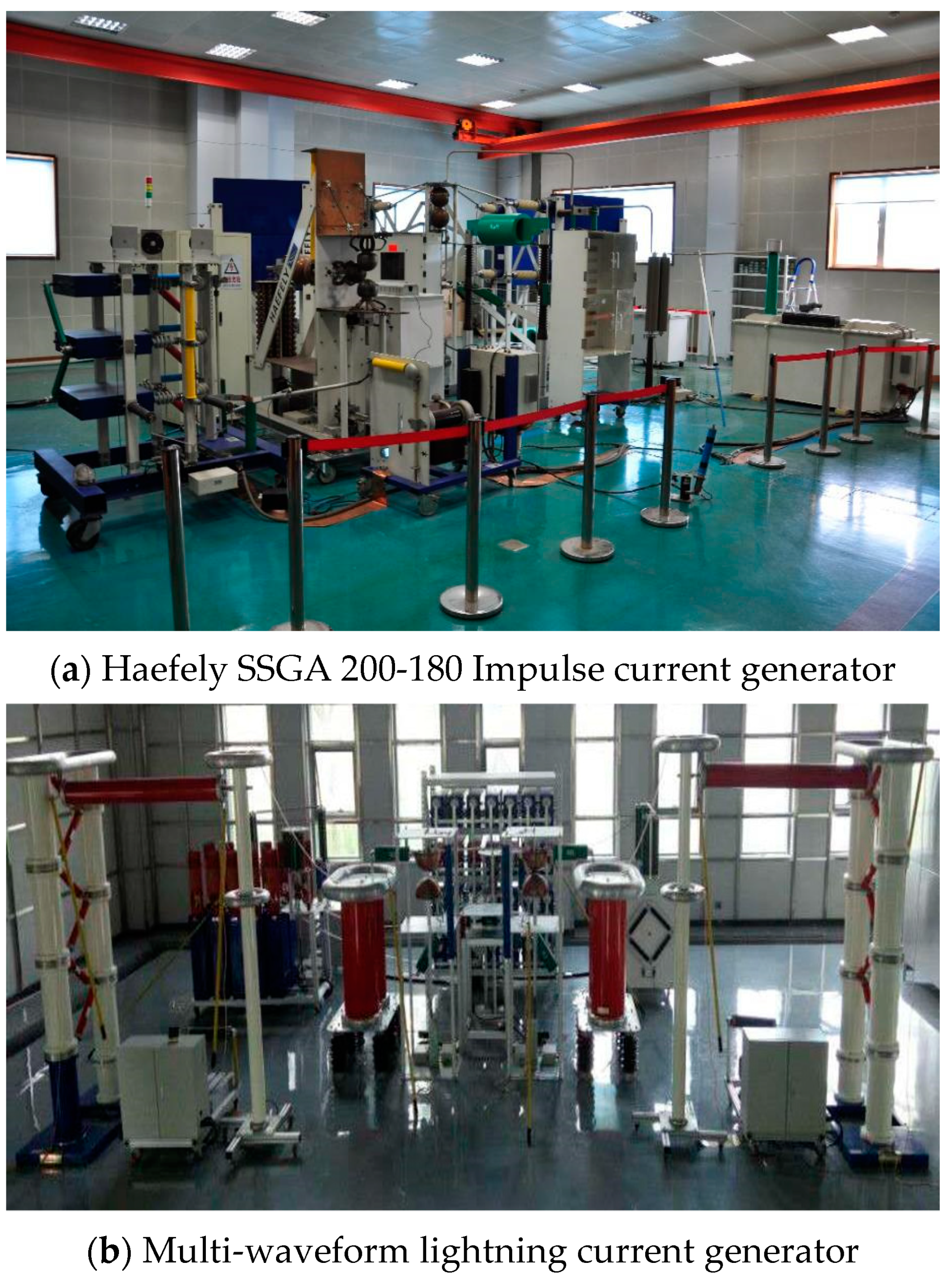
2.2. Test Equipment
2.3. Test Setup
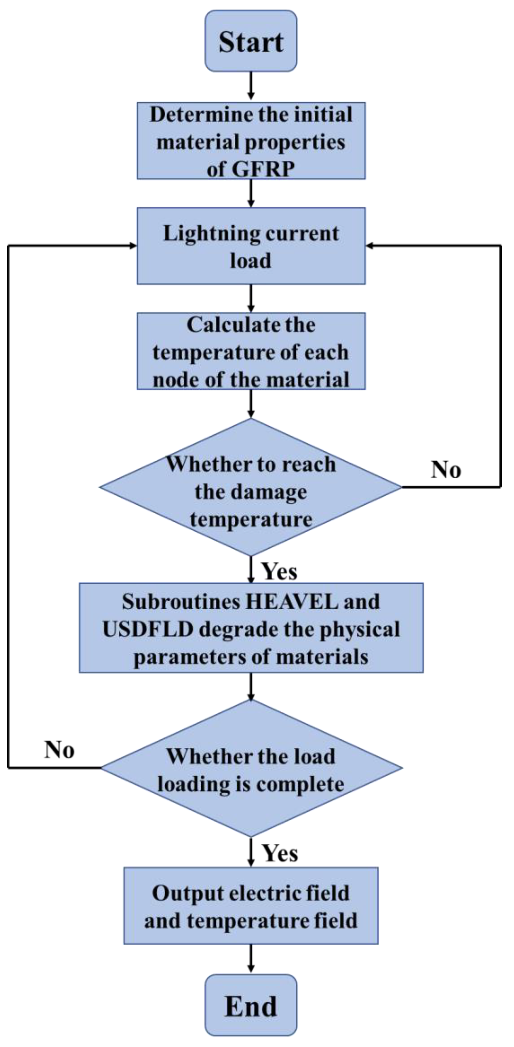
3. Simulation on Lightning Ablation Damage
3.1. Basic Theory
3.1.1. Electric Field Formula
3.1.2. Thermal Balance
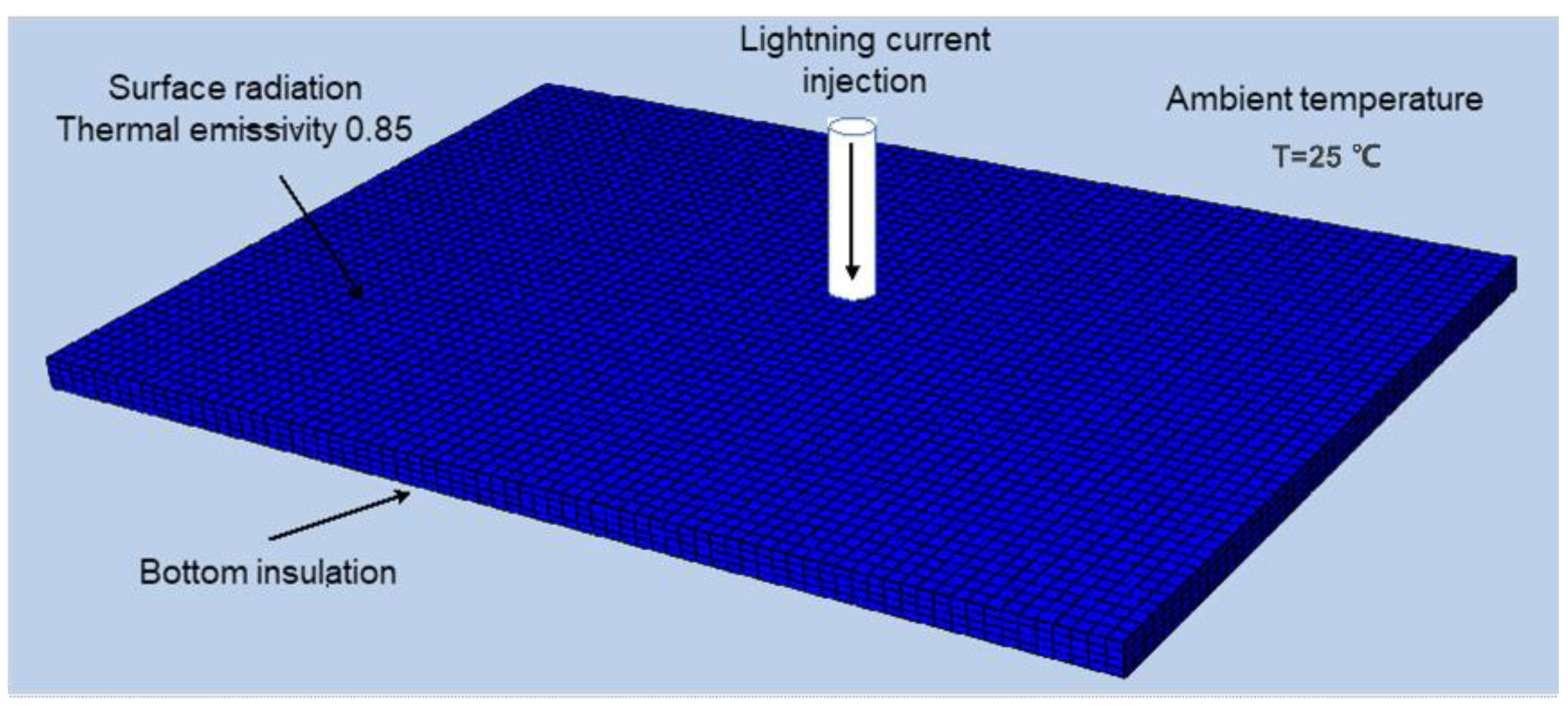
3.2. Surface Ablation Damage Modelling
3.3. Through-Thickness Ablation Damage Modelling
4. Results and Discussion
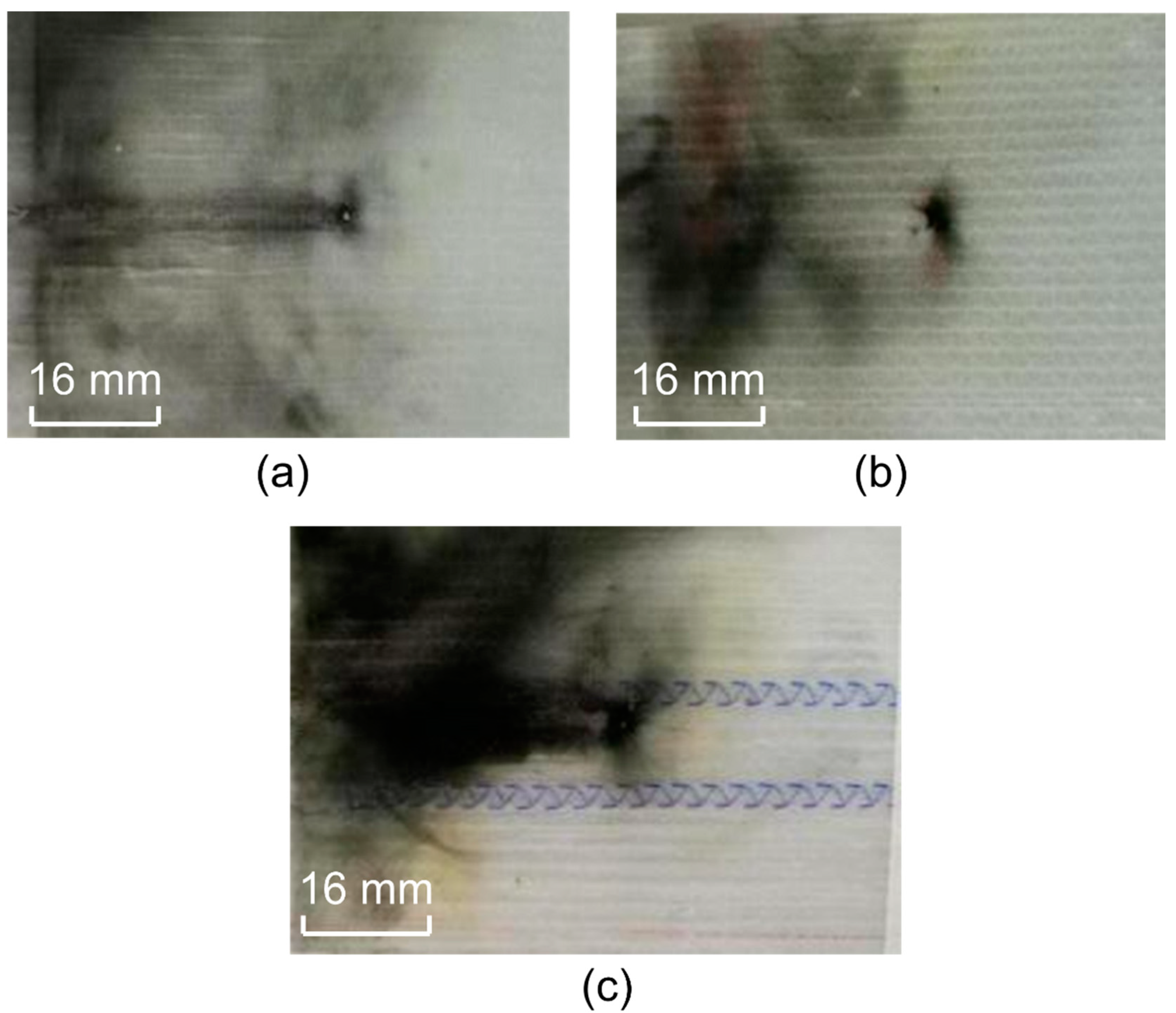
4.1. Experimental Analysis
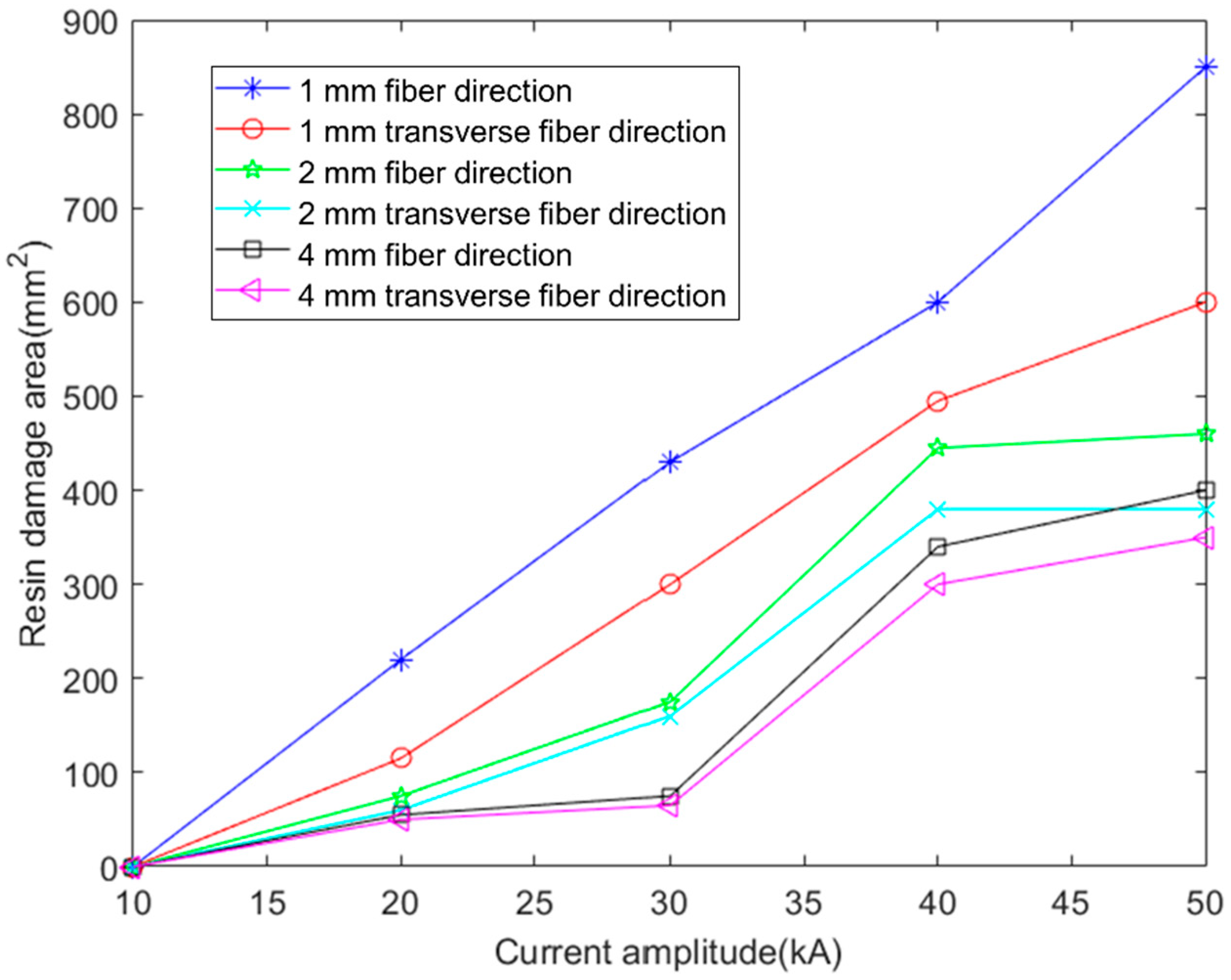
4.1.1. Ablative Damages along the Surface Direction
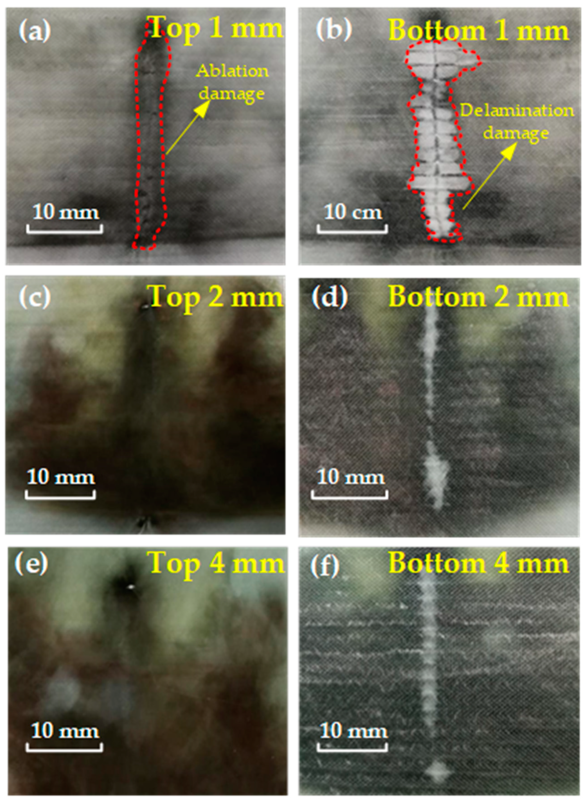
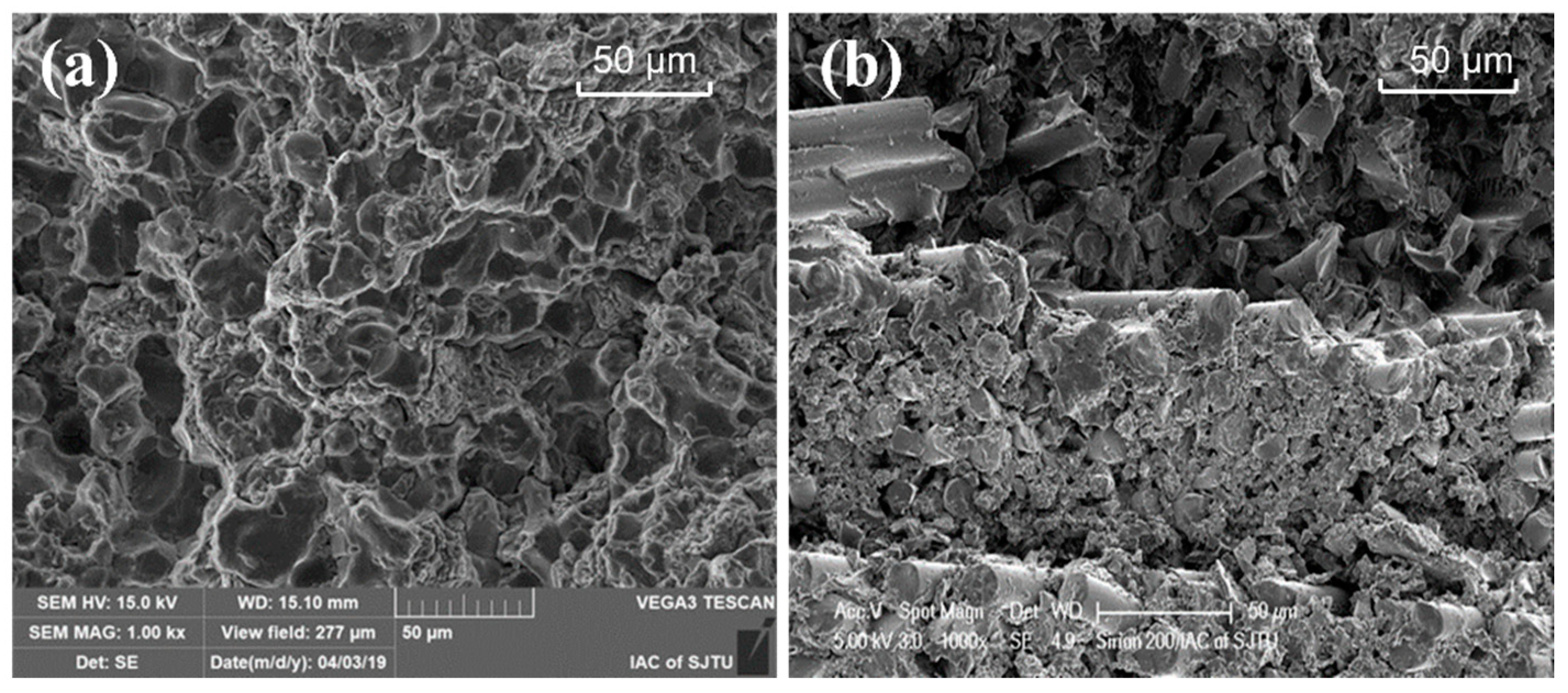
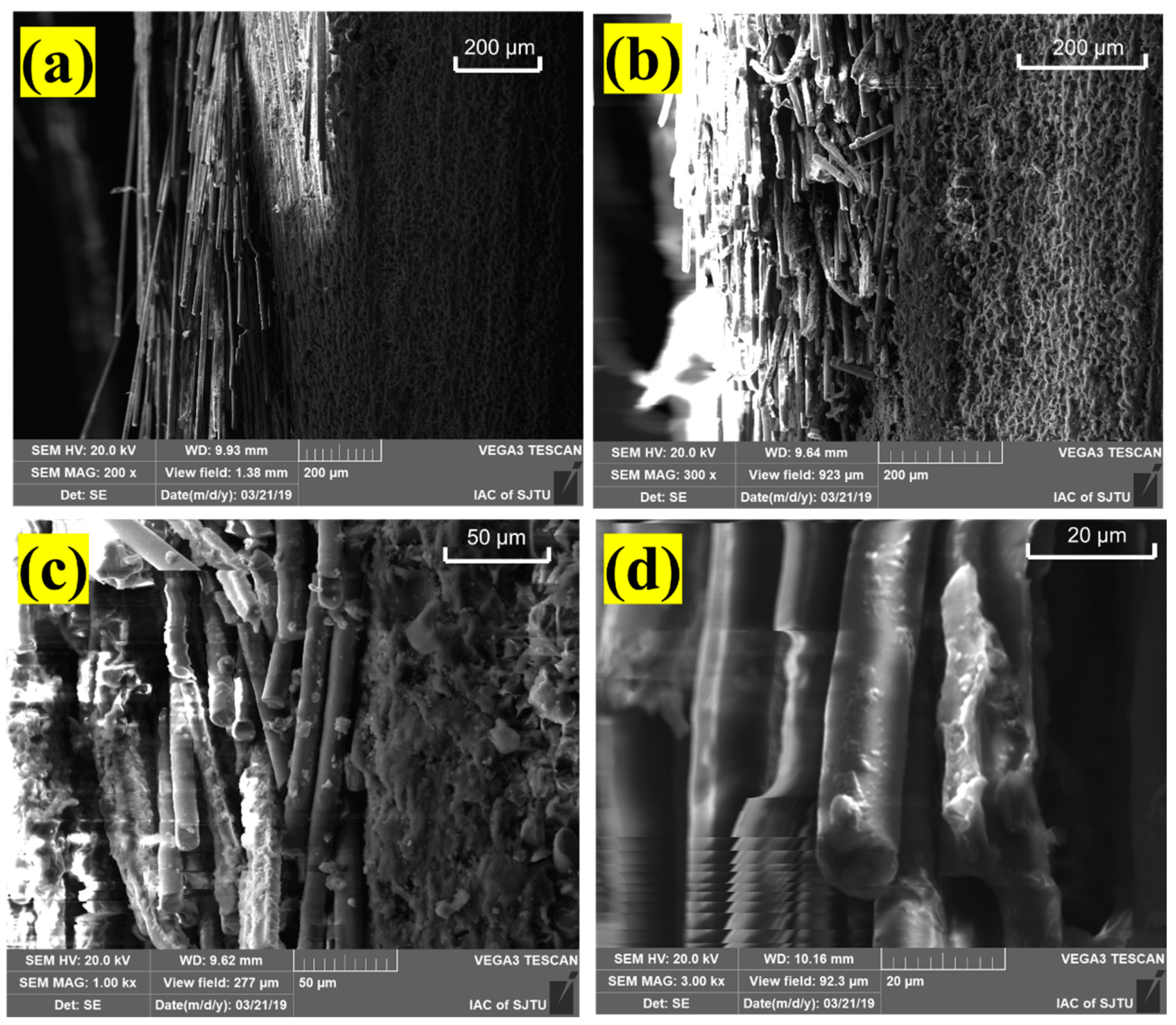
4.1.2. Ablation Damages along the Thickness Direction
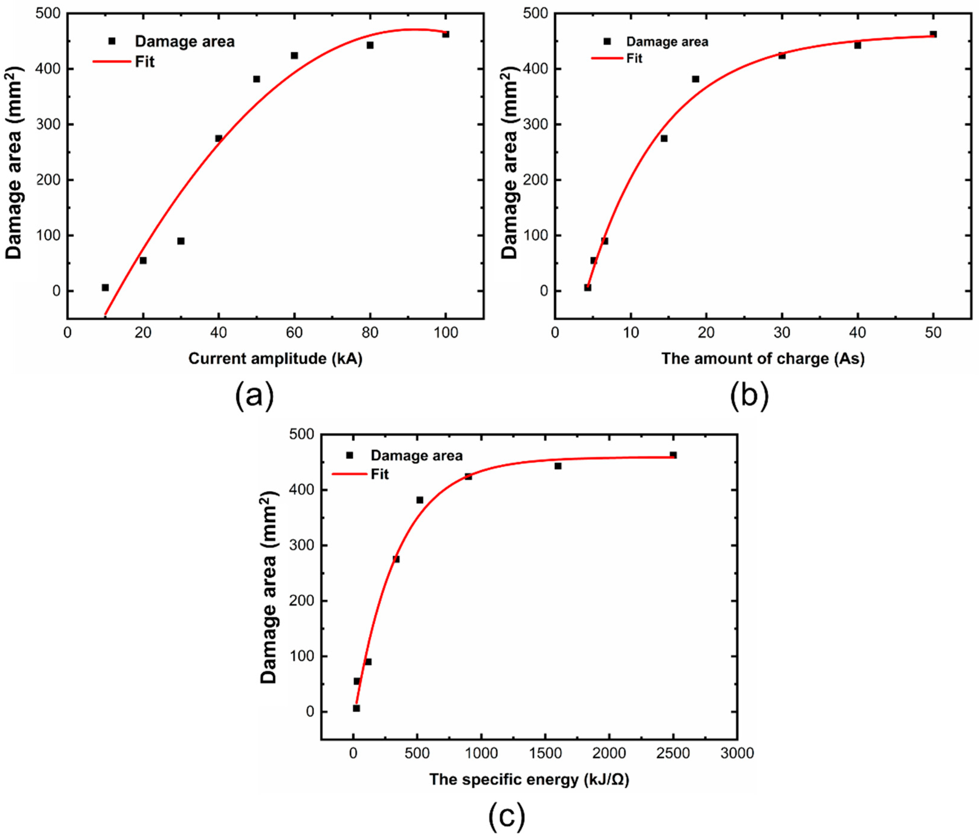
4.2. Numerical Prediction of Lightning Ablation Damage
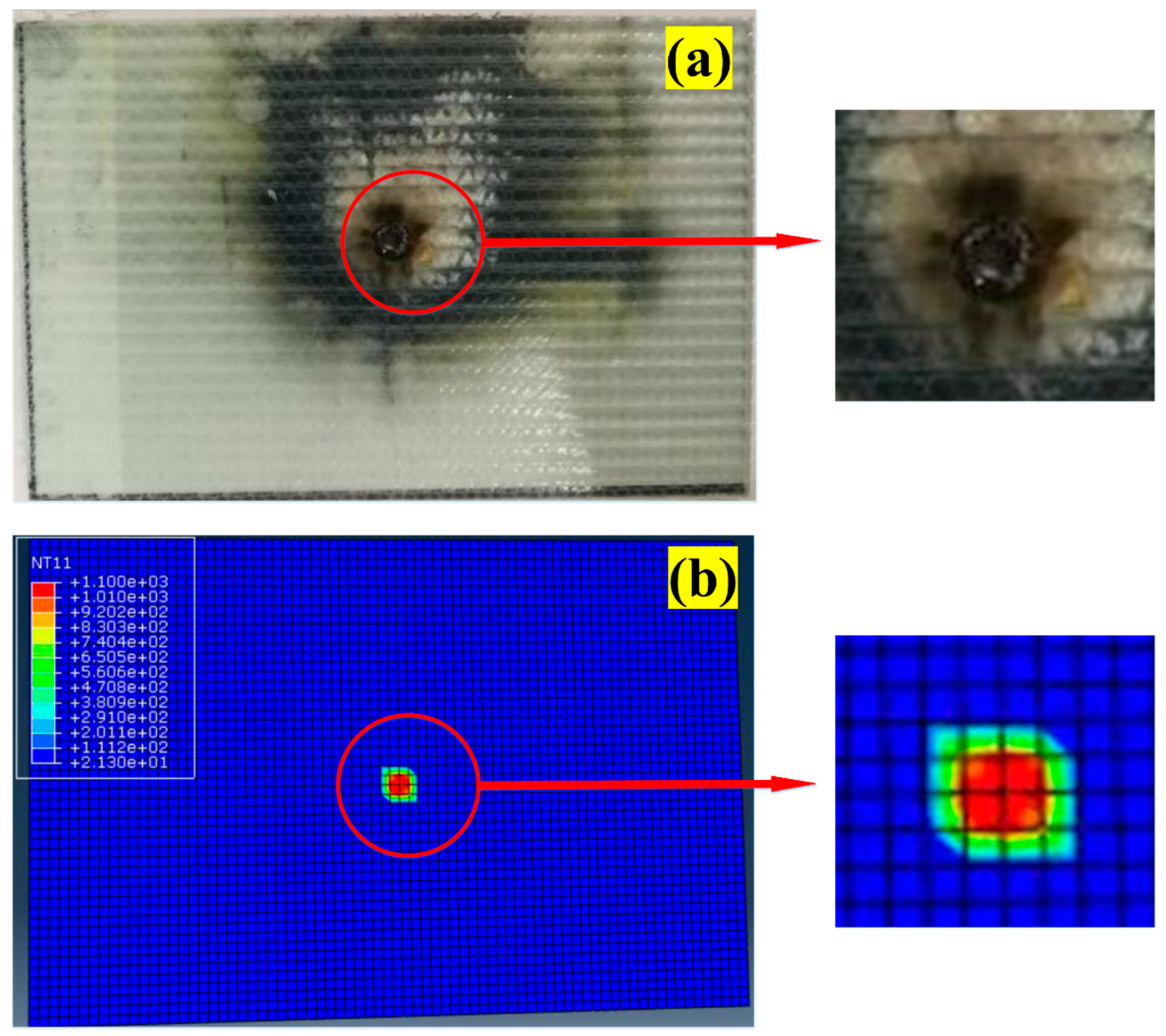
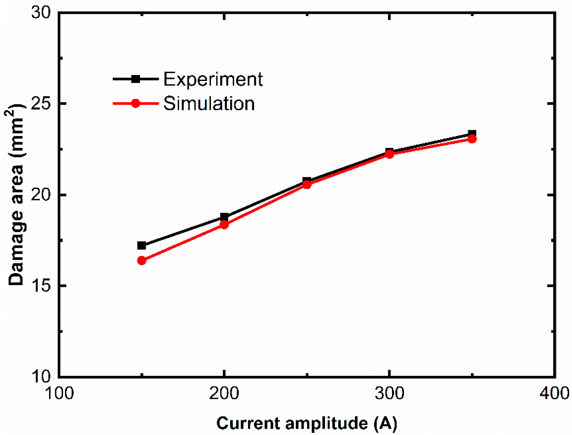
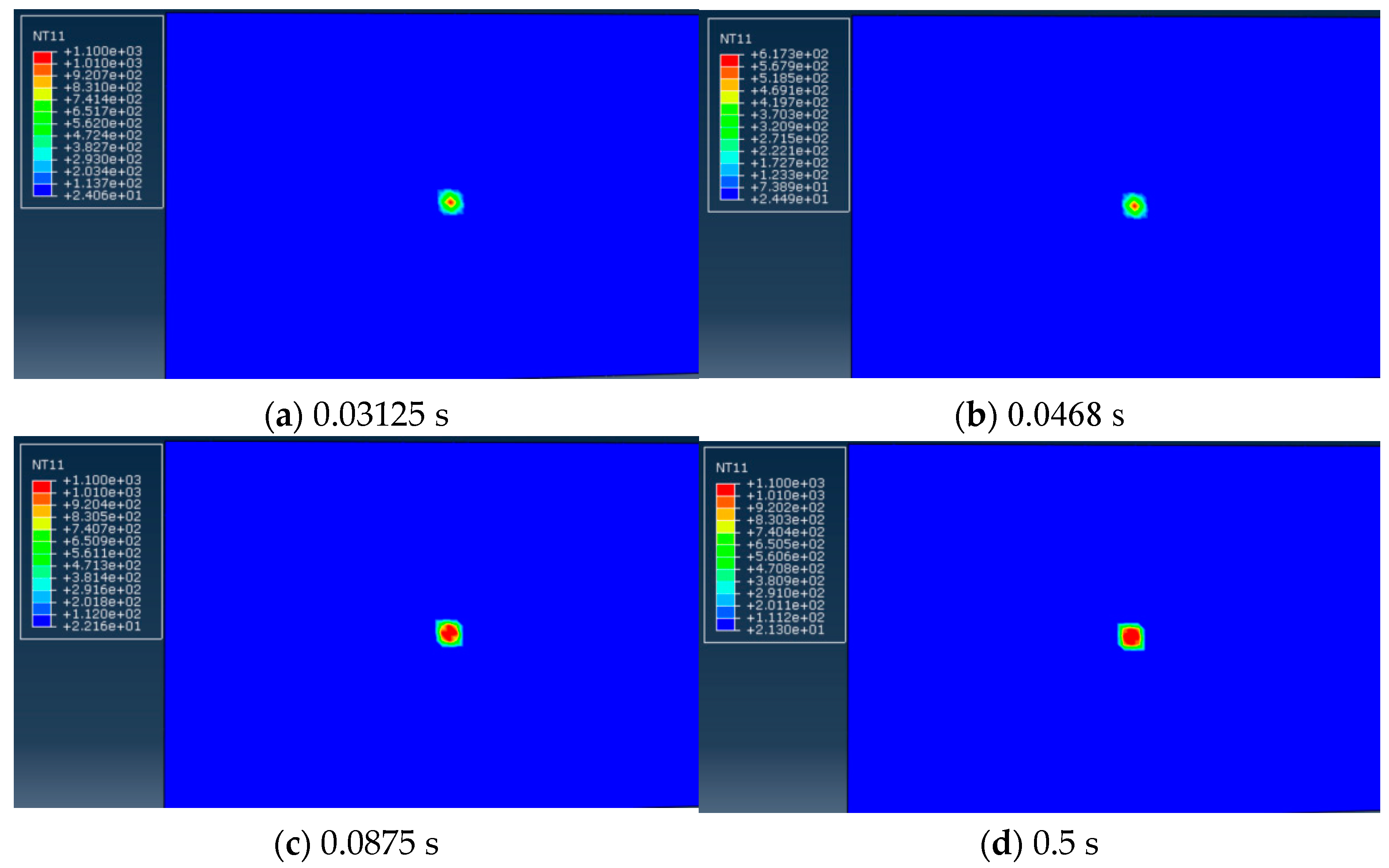
4.2.1. Simulation Analysis of GFRC Ablation Damage along the Surface
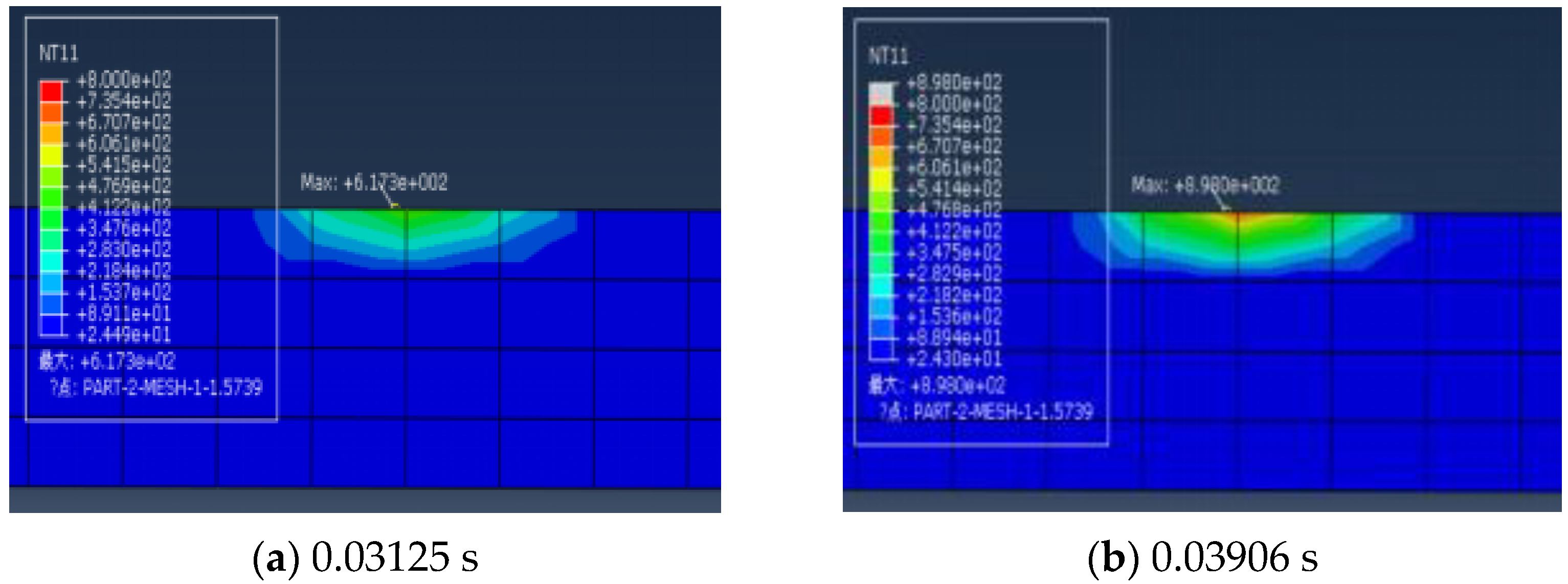
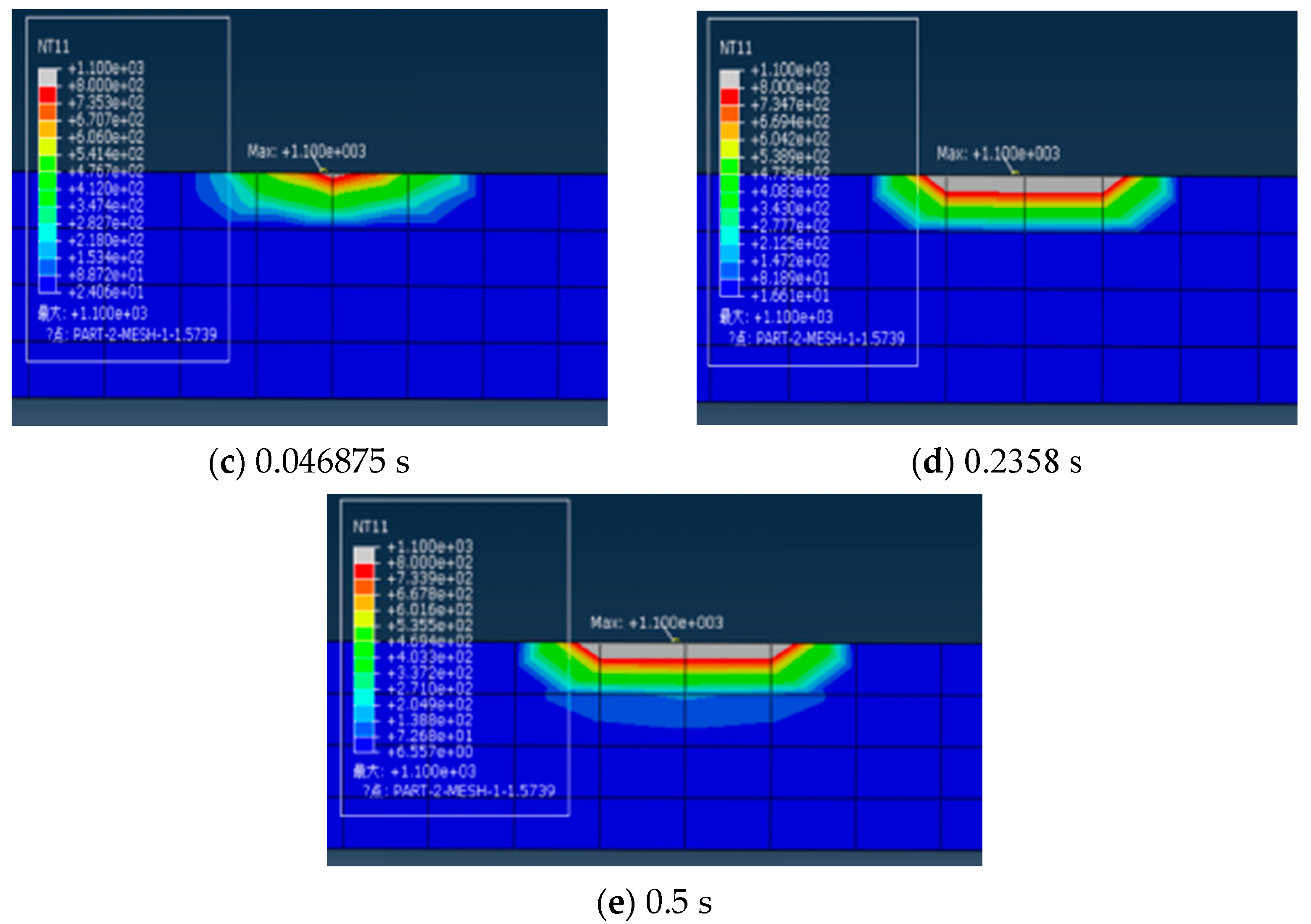
4.2.2. Simulation Analysis of GFRC Ablation Damage along the Thickness
5. Conclusions
- The experimental results showed that the damage of GFRC is mainly affected by the component A, while the influence of the components B and C can be ignored. The material thickness, layer direction, and lightning current parameters are all important factors for the ablation of GFRC under lightning strike.
- Due to the high temperature pyrolysis of the resin and the rapid gasification of the resin during lightning strikes, the stress wave is produced which in turn leads to the fiber breakage and delamination.
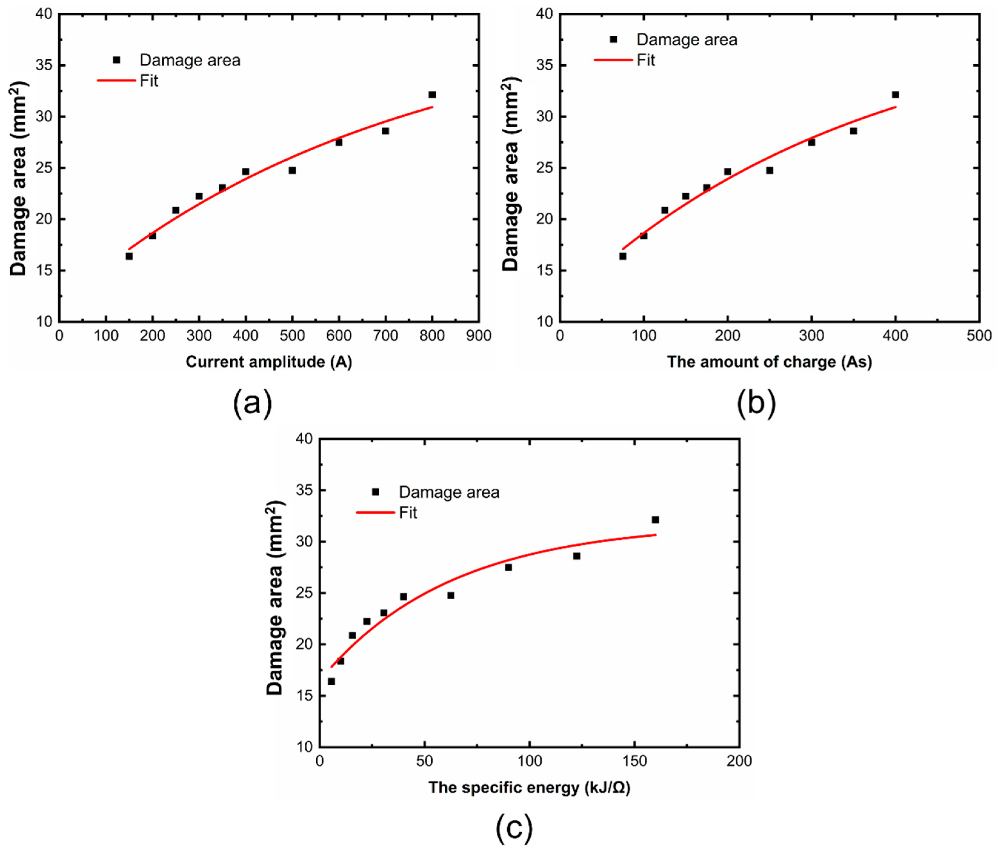
- A thermal-electric coupling simulation model is established, and the simulation results are in good agreement with the experimental results, which verifies that the model can be used to predict the lightning damage of GFRC. The quantitative relationship between the ablation area and the lightning current amplitude, charge amount and specific energy is obtained by data fitting. It can be found that the damage area and the depth of GFRC are positively non-linearly correlated with the lightning current amplitude, the charge amount and the specific energy.
Author Contributions
Funding
Institutional Review Board Statement
Informed Consent Statement
Data Availability Statement
Conflicts of Interest
References
- Zhu, H.; Fu, K.; Yang, B.; Li, Y. Nickel-coated nylon sandwich film for combination of lightning strike protection and electromagnetic interference shielding of CFRP composite. Compos. Sci. Technol. 2021, 207, 108675. [Google Scholar] [CrossRef]
- Hirano, Y.; Yokozeki, T.; Ishida, Y.; Goto, T.; Takahashi, T.; Qian, D.; Ito, S.; Ogasawara, T.; Ishibashi, M. Lightning damage suppression in a carbon fiber-reinforced polymer with a polyaniline-based conductive thermoset matrix. Compos. Sci. Technol. 2016, 127, 1–7. [Google Scholar] [CrossRef]
- Zhang, J.; Zhang, X.; Cheng, X.; Hei, Y.; Xing, L.; Li, Z. Lightning strike damage on the composite laminates with carbon nanotube films: Protection effect and damage mechanism. Compos. Part B Eng. 2019, 168, 342–352. [Google Scholar] [CrossRef]
- Zhao, J.; Chen, X.; Zhang, Y.; Zhang, B. Simulation and test for the lightning damage of the glass fiber composites. FRP/Compos. Mater. 2015, 1, 42–47. [Google Scholar]
- Tao, S.; Liu, M.; He, M.; Yue, Y. Experimental study on lightning damage of glass fiber composite wind turbine blades. Bonding 2021, 46, 60–63. [Google Scholar]
- Yang, C.; Zhao, Y.; Xiao, Y.; Xing, H.; Fu, Z. Experimental study on creepage of GFRP under simulate lightning current. Compos. Mater. Sci. Eng. 2020, 5, 47–52. [Google Scholar]
- Guo, Y.; Xu, Y.; Wang, Q.; Dong, Q.; Yi, X.; Jia, Y. Enhanced lightning strike protection of carbon fiber composites using expanded foils with anisotropic electrical conductivity. Compos. Part A Appl. Sci. Manuf. 2019, 117, 211–218. [Google Scholar] [CrossRef]
- Kawakami, H.; Feraboli, P. Lightning strike damage resistance and tolerance of scarf-repaired mesh-protected carbon fiber composites. Compos. Part A Appl. Sci. Manuf. 2011, 42, 1247–1262. [Google Scholar] [CrossRef]
- Yokoyama, S.; Honjo, N.; Yasuda, Y.; Yamamoto, K. Causes of wind turbine blade damages due to lightning and future research target to get better protection measures. In Proceedings of the 2014 International Conference on Lightning Protection, Shanghai, China, 11–18 October 2014; pp. 823–830. [Google Scholar]
- Yokoyama, S. Lightning protection of wind turbine blades. Electr. Power Syst. Res. 2013, 94, 3–9. [Google Scholar] [CrossRef]
- Yamashita, S.; Hirano, Y.; Sonehara, T. Residual mechanical properties of carbon fibre reinforced thermoplastics with thin-ply prepreg after simulated lightning strike. Compos. Part A Appl. Sci. Manuf. 2017, 101, 185–194. [Google Scholar] [CrossRef]
- Wang, F.S. Experimental and numerical study on residual strength of aircraft carbon/epoxy composite after lightning strike. Aerosp. Sci. Technol. 2018, 75, 304–314. [Google Scholar] [CrossRef]
- Garolera, A.C.; Madsen, S.F.; Nissim, M.; Myers, J.D.; Holboell, J. Lightning damage to wind turbine blades from wind farms in the U.S. IEEE Trans. Power Deliv. 2016, 31, 1043–1049. [Google Scholar] [CrossRef]
- Hirano, Y.; Katsumata, S.; Iwahori, Y.; Todoroki, A. Artificial lightning testing on graphite/epoxy composite laminate. Compos. Part A Appl. Sci. Manuf. 2010, 41, 1461–1470. [Google Scholar] [CrossRef]
- Dong, Q.; Guo, Y.; Sun, X.; Jia, Y. Coupled electrical-thermal-pyrolytic analysis of carbon fiber/epoxy composites subjected to lightning strike. Polymer 2015, 56, 385–394. [Google Scholar] [CrossRef]
- Fu, K.; Ye, L.; Zhong, Z. Modelling of lightning strike damage to CFRP composites with an advanced protection system. Part I: Thermal–electrical transition. Compos. Struct. 2017, 165, 83–90. [Google Scholar] [CrossRef]
- Yao, X.; Guo, C.; Sun, J.; Chen, J. Damage simulation and experiment of carbon fiber composites subjected to lightning current. High Volt. Technol. 2017, 43, 1400–1408. [Google Scholar]
- Zhang, Y.; Wen, X.; Wang, J.; Deng, Y.; Lan, L.; Wang, Y. Arifical lightning testing on wind turbine: Epoxy composite laminate. J. Wuhan Univ. (Eng. Ed.) 2019, 52, 264–269. [Google Scholar]
- Guo, Z.; Li, Q.; Yu, W.; Arif, W.; Ma, Y.; Siew, W.H. Experimental study on lightning attachment manner to rotation wind turbine blade. In Proceedings of the 2018 34th International Conference on Lightning Protection, Rzeszow, Poland, 2–7 September 2018. [Google Scholar]
- ASTM D7137_D7137M-07. Standard Test Method for Compressive Residual Strength Properties of Damaged Polymer Matrix Composite Plates; American Society for Testing and Materials (ASTM): West Conshohocken, PA, USA, 2007. [Google Scholar]
- Abdelal, G.; Murphy, A. Nonlinear numerical modelling of lightning strike effect on composite panels with temperature dependent material properties. Compos. Struct. 2014, 109, 268–278. [Google Scholar] [CrossRef] [Green Version]
- Wang, Y.; Zhupanska, O.I. Modeling of thermal response and ablation in laminated glass fiber reinforced polymer matrix composites due to lightning strike. Appl. Math. Model. 2018, 53, 118–131. [Google Scholar] [CrossRef]
- Wang, Y.; Zhupanska, O.I. Lightning strike thermal damage model for glass fiber reinforced polymer matrix composites and its application to wind turbine blades. Compos. Struct. 2015, 132, 1182–1191. [Google Scholar] [CrossRef]
- Fu, K.; Ye, L. Modelling of Lightning-induced Dynamic Response and Mechanical Damage in CFRP Composite Laminates with Protection. Compos. Struct. 2019, 218, 162–173. [Google Scholar] [CrossRef]


| Temperature/°C | Density/(kg/mm3) | Specific Heat Capacity/(J·kg−1 °C) | Thermal Conductivity /(W·m−1·°C) | Electricity Conductivity /(Ω·mm)−1 | ||||
|---|---|---|---|---|---|---|---|---|
| Longitudinal Direction | In-Depth Direction | Transverse Direction | Longitudinal Direction | In-Depth Direction | Transverse Direction | |||
| 25 | 1200 | 956.3784 | 0.7761 | 0.2663 | 0.2661 | 1 × 10⁻⁸ | 1 × 10⁻⁹ | 1 × 10⁻⁹ |
| 300 | 1200 | 967.2042 | 0.7795 | 0.2792 | 0.2801 | 1 × 10⁻⁸ | 1 × 10⁻⁹ | 1 × 10⁻⁹ |
| 600 | 1200 | 1106.803 | 0.8122 | 0.3939 | 0.393 | 1 × 10⁻⁶ | 1 × 10⁻⁶ | 1 × 10⁻⁶ |
| 900 | 1200 | 1174.09 | 0.85 | 0.5125 | 0.5104 | 1 × 10⁻⁶ | 1 × 10⁻⁶ | 1 × 10⁻⁶ |
| 1100 | 1200 | 1174.09 | 0.8539 | 0.5135 | 0.5117 | 1 × 10⁻⁶ | 1 × 10⁻⁶ | 1 × 10⁻⁶ |
| >1100 | 1200 | 1174.09 | 1 | 1 | 1 | 1 × 10⁻⁶ | 1 × 10⁻⁶ | 1 × 10⁻⁶ |
| Iimp (A) | QS (As) | Specific Energy W/R (kJ/Ω) |
|---|---|---|
| 150 | 75 | 5.625 |
| 200 | 100 | 10 |
| 250 | 125 | 15.625 |
| 300 | 150 | 22.5 |
| 350 | 175 | 30.625 |
| 400 | 200 | 40 |
| 500 | 250 | 62.5 |
| 600 | 300 | 90 |
| 700 | 350 | 122.5 |
| 800 | 400 | 160 |
| 10 kA | 30 kA | 50 kA | |
|---|---|---|---|
| Experimental | 6.73 | 89.43 | 396.85 |
| Simulation | 6.29 | 86.72 | 381.59 |
| Current Amplitude | 150 A | 200 A | 250 A | 300 A | 350 A |
| Experiment | 17.21 | 18.78 | 20.74 | 22.35 | 23.34 |
| Simulation | 16.39 | 18.36 | 20.56 | 22.23 | 23.07 |
Publisher’s Note: MDPI stays neutral with regard to jurisdictional claims in published maps and institutional affiliations. |
© 2021 by the authors. Licensee MDPI, Basel, Switzerland. This article is an open access article distributed under the terms and conditions of the Creative Commons Attribution (CC BY) license (https://creativecommons.org/licenses/by/4.0/).
Share and Cite
Zhao, Y.; Yang, B.; Zhang, Y. Experimental Research and Simulation Analysis of Lightning Ablation Damage Characteristics of Megawatt Wind Turbine Blades. Metals 2021, 11, 1251. https://doi.org/10.3390/met11081251
Zhao Y, Yang B, Zhang Y. Experimental Research and Simulation Analysis of Lightning Ablation Damage Characteristics of Megawatt Wind Turbine Blades. Metals. 2021; 11(8):1251. https://doi.org/10.3390/met11081251
Chicago/Turabian StyleZhao, Yang, Bin Yang, and Yao Zhang. 2021. "Experimental Research and Simulation Analysis of Lightning Ablation Damage Characteristics of Megawatt Wind Turbine Blades" Metals 11, no. 8: 1251. https://doi.org/10.3390/met11081251
APA StyleZhao, Y., Yang, B., & Zhang, Y. (2021). Experimental Research and Simulation Analysis of Lightning Ablation Damage Characteristics of Megawatt Wind Turbine Blades. Metals, 11(8), 1251. https://doi.org/10.3390/met11081251