
Fatigue Variability of Alloy 625 Thin-Tube Brazed Specimens


Abstract
:1. Introduction
2. Experiments
3. Results and Discussion
4. Conclusions
Author Contributions
Funding
Data Availability Statement
Conflicts of Interest
References
- McDonald, C.F.; Wilson, D.G. The utilization of recuperated and regenerated engine cycles for high-efficiency gas turbines in the 21st century. Appl. Therm. Eng. 1996, 16, 635–653. [Google Scholar] [CrossRef]
- Wilfert, G.; Sieber, J.; Rolt, A.; Baker, N.; Touyeras, A.; Colantuoni, S. New Environmental Friendly Aero Engine Core Concepts. In Proceedings of the XVIII International Symposium of Air Breathing Engines, The International Society for Air Breathing Engines (ISABE), Beijing, China, 2–7 September 2007. [Google Scholar]
- Jeong, J.H.; Kim, L.S.; Lee, J.K.; Ha, M.Y.; Kim, K.S.; Ahn, Y.C. Review of heat exchanger studies for high-efficiency gas turbines. In Proceedings of the Turbo Expo: Power for Land, Sea, and Air, American Society of Mechanical Engineers, Montreal, CA, USA, 14–17 May 2007. [Google Scholar]
- McDonald, C.F. Recuperator considerations for future higher efficiency microturbines. Appl. Therm. Eng. 2003, 23, 1463–1487. [Google Scholar] [CrossRef]
- Min, J.K.; Jeong, J.H.; Ha, M.Y.; Kim, K.S. High temperature heat exchanger studies for applications to gas turbines. Heat Mass Transf. 2009, 46, 175–186. [Google Scholar] [CrossRef]
- Bruening, G.B.; Chang, W.S. Cooled cooling air systems for turbine thermal management. In Proceedings of the ASME 1999 International Gas Turbine and Aeroengine Congress and Exhibition, Proceeding of the Turbo Expo: Power for Land, Sea, and Air, American Society of Mechanical Engineers, Indianapolis, IN, USA, 7–10 June 1999. [Google Scholar]
- Maziasz, P.J.; Pint, B.A.; Shingledecker, J.P.; Evans, N.D.; Yamamoto, Y.; More, K.L.; Lara-Curzio, E. Advanced alloys for compact, high-efficiency, high-temperature heat-exchangers. Int. J. Hydrog. Energ. 2007, 32, 3622–3630. [Google Scholar] [CrossRef]
- MacKenzie, P.M.; Walker, C.A.; McKelvie, J. A method for evaluating the mechanical performance of thin-walled titanium tubes. Thin-Walled Struct. 2007, 45, 400–406. [Google Scholar] [CrossRef] [Green Version]
- Sonsino, C.M.; Bruder, T.; Baumgartner, J. S-N Lines for welded thin joints-suggested slopes and fat values for applying the notch stress concept with various reference radii. Weld. J. 2010, 54, R375–R392. [Google Scholar] [CrossRef]
- Fayard, J.L.; Bignonnet, A.; Van, K.D. Fatigue design criterion for welded structures. Fatigue Fract. Eng. Mater. Struct. 1996, 19, 723–729. [Google Scholar] [CrossRef]
- Lazzarin, P.; Sonsino, C.M.; Zambardi, R. A notch stress intensity approach to assess the multiaxial fatigue strength of welded tube-to-flange joints subjected to combined loadings. Fatigue Fract. Eng. Mater. Struct. 2004, 27, 127–140. [Google Scholar] [CrossRef]
- Yokobori, T.; Yamanouchi, H.; Yamamoto, S. Low cycle fatigue of thin-walled hollow cylindrical specimens of mild steel in uni-axial and torsional tests at constant strain amplitude. Int. J. Fract. 1965, 1, 3–13. [Google Scholar] [CrossRef]
- Carstensen, J.; Mayer, H.; Brøndsted, P. Very high cycle regime fatigue of thin walled tubes made from austenitic stainless steel. Fatigue Fract. Eng. Mater. Struct. 2002, 25, 837–844. [Google Scholar] [CrossRef]
- Baumgartner, J.; Tillmann, W.; Bobzin, K.; Ote, M.; Wiesner, S.; Sievers, N. Fatigue of brazed joints made of X5CrNi18-10 and Cu110 and derivation of reliable assessment approaches. Weld. World. 2020, 64, 707–719. [Google Scholar] [CrossRef] [Green Version]
- Floreen, S.; Fuchs, G.E.; Yang, W.J. The Metallurgy of Alloy 625. Superalloys 1994, 718, 13–37. [Google Scholar]
- Radavich, J.F.; Fort, A. Effects of Long-Time Exposure in Alloy 625 at 1200 °F, 1400 °F and 1600 °F. Superalloys 1994, 718, 635–647. [Google Scholar]
- Conder, C.R.; Smith, G.D. Microstructural and mechanical property characterization of aged Inconel625LCF. In Proceedings of the International Symposium on Superalloys 718, 625, 706 and Various Derivatives; The Minerals, Metals, and Materials Society (TMS): Pittsburgh, PA, USA, 1997; pp. 447–458. [Google Scholar]
- Marchese, G.; Beretta, M.; Aversa, A.; Biamino, S. In situ alloying of a modified Inconel 625 via laser powder bed fusion: Microstructure and mechanical properties. Metals 2021, 11, 988. [Google Scholar] [CrossRef]
- Shankar, V.; Valsan, M.; Rao, K.B.S.; Mannan, S.L. Effects of temperature and strain rate on tensile properties and activation energy for dynamic strain aging in alloy 625. Metall. Mater. Trans. A: Phys. Metall. Mater. Sci. 2004, 35A, 3129–3139. [Google Scholar] [CrossRef]
- Suave, L.M.; Cormier, J.; Bertheau, D.; Villechaise, R.; Soula, A.; Hervier, Z.; Hamon, F. High temperature low cycle fatigue properties of alloy 625. Mater. Sci. Eng. A 2016, 630, 161–170. [Google Scholar] [CrossRef]
- Osoba, L.O.; Ojo, O.A. Influence of solid-state diffusion during equilibration on microstructure and fatigue life of superalloy wide gap brazements. Metall. Mater. Trans. A 2013, 44, 4020–4024. [Google Scholar] [CrossRef]
- Yang, X.; Dong, C.; Shi, D.; Zhang, L. Experimental Investigation on Both Low Cycle Fatigue and Fracture Behavior of DZ125 Base Metal and the Brazed Joint at Elevated Temperature. Mater. Sci. Eng. A 2011, 528, 7005–7011. [Google Scholar] [CrossRef]
- Shi, D.; Dong, C.; Yang, X.; Sun, Y.; Wang, J.; Liu, J. Creep and fatigue lifetime analysis of directionally solidified superalloy and its brazed joints based on continuum damage mechanics at elevated temperature. Mater. Des. 2013, 45, 643–652. [Google Scholar] [CrossRef]
- Kim, Y.H.; Kim, I.H.; Kim, C.S. Asian Pacific Conference for Fracture and Strength, 4th ed.; Trans Tech Publications Ltd.: Bäch SZ, Switzerland, 2005; pp. 2876–2882. [Google Scholar]
- Kim, Y.H.; Kim, K.T. Multifunctional Materials and Structures; Trans Tech Publications Ltd.: Bäch SZ, Switzerland, 2008; pp. 894–897. [Google Scholar]
- Chen, J.; Deners, V.; Turner, D.P.; Bocher, P. Experimental investigation on high-cycle fatigue of Inconel 625 superalloy brazed joints. Metall. Mater. Trans. A: Phys. Metall. Mater. Sci. 2018, 49A, 1244–1253. [Google Scholar] [CrossRef]
- Chen, J.; Demers, V.; Cadotte, E.-L.; Turner, D.; Bocher, P. Structural performance of Inconel 625 superalloy brazed joints. J. Mater. Eng. Perform. 2017, 26, 547–553. [Google Scholar] [CrossRef]
- Pouranvari, M.; Ekrami, A.; Kokabi, A.H. Solidification and solid state phenomena during TLP bonding of IN718 superalloy using Ni–Si–B ternary filler alloy. J. Alloys Compd. 2013, 563, 143–149. [Google Scholar] [CrossRef]
- Tung, S.K.; Lim, L.C.; Lai, M.O. Solidification phenomena in nickel base brazes containing boron and silicon. Scr. Mater. 1996, 34, 763–769. [Google Scholar] [CrossRef]
- Garrell, M.G.; Shih, A.J.; Lara-Curzio, E.; Scattergood, R.O. Finite-element analysis of stress concentration in ASTM D 638 tension specimens. J. Test. Eval. 2003, 31, 1–6. [Google Scholar]
- Kang, S.-H.; Park, S.H.; Min, J.K.; Cho, J.R.; Ha, M.-Y. Evaluation of mechanical integrity on the brazing joint of a tube-type heat exchanger with considering local material properties. Proc. Inst. Mech. Eng. C 2013, 227, 420–433. [Google Scholar] [CrossRef]
- Zhang, Y.-C.; Yu, X.-T.; Jiang, W.; Tu, S.-T.; Zhang, X.-C. Elastic modulus and hardness characterization for microregion of Inconel 625/BNi-2 vacuum brazed joint by high temperature nanoindentation. Vacuum 2020, 181, 109582. [Google Scholar] [CrossRef]


| Composition (wt.%) | ||||||||||||
|---|---|---|---|---|---|---|---|---|---|---|---|---|
| Ni | Cr | Fe | Co | Mo | Nb | Ti | Al | C | Mn | Si | B | |
| Alloy 625 | 61.4 | 21.2 | 4.7 | 0.1 | 8.6 | 3.34 | 0.18 | 0.14 | 0.03 | 0.07 | 0.20 | - |
| BNi-2 | 82 | 7 | 3 | - | - | - | - | - | - | - | 4.5 | 3.1 |
| Test Temperature (K) | Fatigue Limit (Cycles) | Test Type | Stress Ratio, R | Loading Frequency (Hz) | Maximum Stress Level, σmax (MPa) |
|---|---|---|---|---|---|
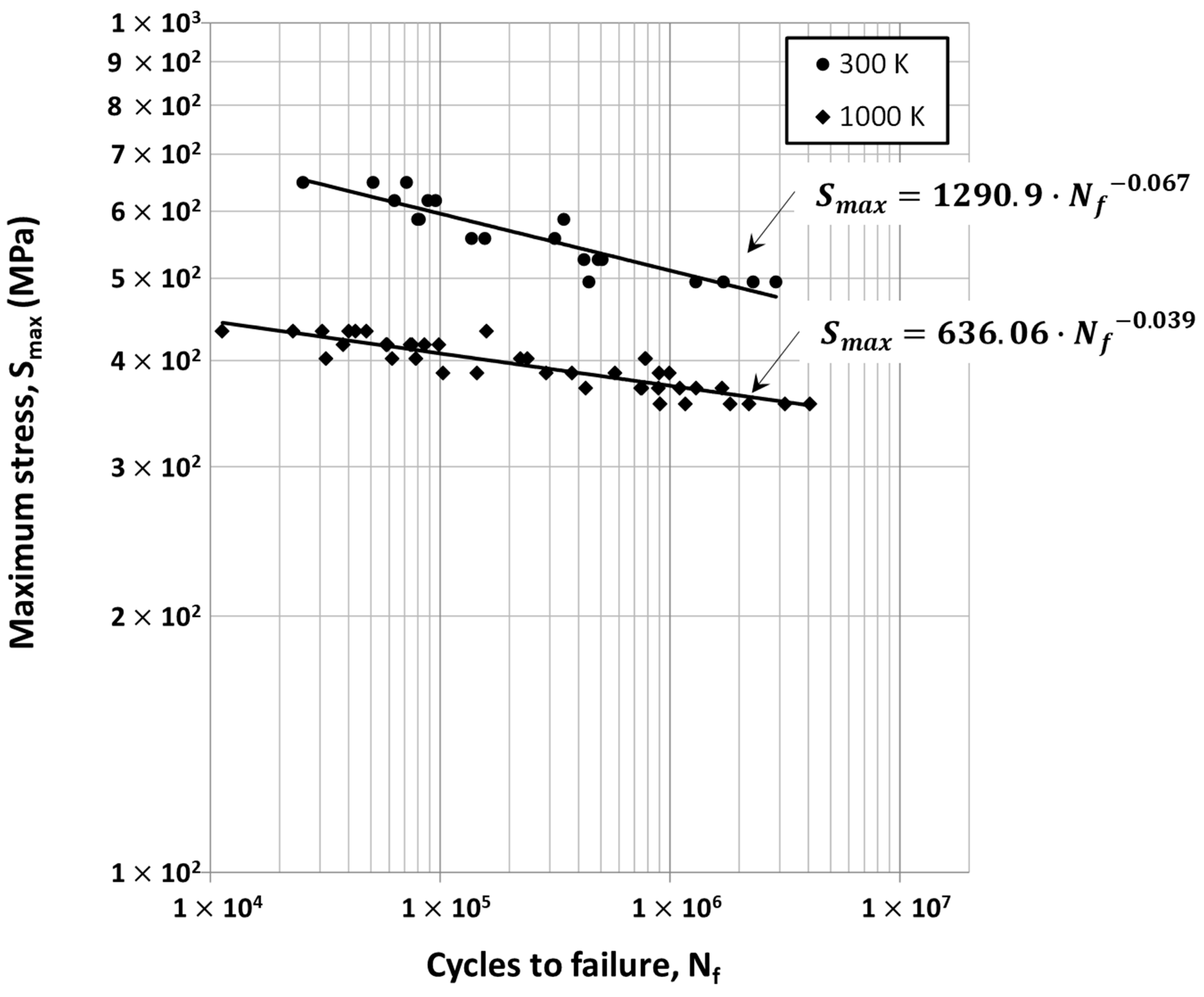
| 300 | 1 106 | Tension–tension cyclic loading | 0.1 | 10 | 495, 526, 557, 587, 618, 649 |
| 1000 | 355, 371, 386, 402, 418, 433 |
| Standard Deviation | Fatigue Strength (MPa) | Reliability (%) | |
|---|---|---|---|
| RT | 1000 K | ||
| 490 | 357 | 84.2 | |
| 468 | 343 | 97.7 | |
| 446 | 329 | 99.9 | |
Publisher’s Note: MDPI stays neutral with regard to jurisdictional claims in published maps and institutional affiliations. |
© 2021 by the authors. Licensee MDPI, Basel, Switzerland. This article is an open access article distributed under the terms and conditions of the Creative Commons Attribution (CC BY) license (https://creativecommons.org/licenses/by/4.0/).
Share and Cite
Lee, S.; Kim, H.; Park, S.; Choi, Y.S. Fatigue Variability of Alloy 625 Thin-Tube Brazed Specimens. Metals 2021, 11, 1162. https://doi.org/10.3390/met11081162
Lee S, Kim H, Park S, Choi YS. Fatigue Variability of Alloy 625 Thin-Tube Brazed Specimens. Metals. 2021; 11(8):1162. https://doi.org/10.3390/met11081162
Chicago/Turabian StyleLee, Seulbi, Hanjong Kim, Seonghun Park, and Yoon Suk Choi. 2021. "Fatigue Variability of Alloy 625 Thin-Tube Brazed Specimens" Metals 11, no. 8: 1162. https://doi.org/10.3390/met11081162
APA StyleLee, S., Kim, H., Park, S., & Choi, Y. S. (2021). Fatigue Variability of Alloy 625 Thin-Tube Brazed Specimens. Metals, 11(8), 1162. https://doi.org/10.3390/met11081162