Article

Influence of Post-Deposition Heat Treatments on the Microstructure and Tensile Properties of Ti-6Al-4V Parts Manufactured by CMT-WAAM

LORTEK Technological Centre, Basque Research and Technology Alliance (BRTA), 20240 Ordizia, Spain
*
Author to whom correspondence should be addressed.
Metals 2021, 11(8), 1161; https://doi.org/10.3390/met11081161
Submission received: 25 June 2021 / Revised: 19 July 2021 / Accepted: 20 July 2021 / Published: 22 July 2021
(This article belongs to the Special Issue Wire Arc Additive Manufacturing of Metallic Components)

Abstract

:
Cold metal transfer (CMT)-based wire and arc additive manufacturing (WAAM) of Ti-6Al-4V alloy has been investigated to manufacture walls with two different building strategies. This study focuses on the influence of the application of thermal treatments on the resulting microstructure and mechanical properties. Deep microstructural analysis revealed different grades of growth of lamellae α phase after several thermal treatments at different temperatures, which lead to different tensile mechanical properties and better strength and ductility balance compared to the as-built condition. Results are compared with equivalent forged and casting standards and the state of the art for WAAM of Ti-6Al-4V alloy. At temperatures of 920 °C, anisotropy was maintained and elongation increased by 70% while yield strength and UTS was slightly decreased by 8%.

1. Introduction

Wire and arc additive manufacturing (WAAM) offers interesting advantages over conventional manufacturing [1]. This is due to a great reduction in the buy-to-fly (BTF) ratio which is considerably smaller than in parts machined from oversized billets. In addition, WAAM allows higher deposition rates comparing to other AM technologies, especially to those classified in the powder bed fusion category. In these terms, Ti-6Al-4V is one of the most appealing materials used by the aerospace industry due to its advanced properties such as high strength, low density and outstanding corrosion resistance, among others. The high cost of Ti-6Al-4V makes WAAM highly suitable for the production of large-scale structural components of medium complexity due to the great amount of material saved (BTF ratios close to 1.5) and the great resource consumption efficiency (well above 70%) that can be achieved [2,3,4].
WAAM uses metallic continuous wire as feedstock and can be performed by any arc welding technology. However, as observed in previous works where deposition rates with different arc welding technologies were compared for Ti-6Al-4V, cold metal transfer (CMT) from Fronius offers great advantages [5,6,7]. Apart from deposition rates, CMT also greatly reduces the heat input, which reduces residual stresses, distortion and avoids problems like collapse due to heat accumulation.
In order to satisfy the severe requirements of the aerospace sector to approve a process for the manufacturing of flying-approved parts, WAAM has to demonstrate that it can reach or exceed the mechanical properties obtained by casting or/and forging processes. The standards applied to equivalent Ti-6Al-4V cast material are 8% for elongation and 860 MPa for ultimate tensile strength (UTS) (ASTM F1108). In the case of wrought material, the standards are 10% and 930 MPa, respectively (ASTM F1472) [1].
The typical microstructure of this alloy is an α phase lamellae immersed in a β matrix, called a Widmanstätten structure, as can be observed in Figure 1 [1,8]. The WAAM process entails high and successive thermal variations due to the repeated application of layers which implies high heating and cooling rates in the newly deposited layers and reheating of previously deposited layers. This affects the resulting microstructure, phase balance and morphology. Resulting microstructure and residual stress level are directly linked to the final mechanical properties. Normally, larger α lamellae implies lower UTS [1].
Depending on the cooling rate from the β transus temperature, different microstructures can be found in Ti-6Al-4V material. At very low cooling rates, α in the grain boundaries (αGB) is first formed around prior β grains. After the formation of αGB, primary α is formed in parallel lamellae, forming colonies, oriented perpendicularly to the αGB. If the cooling rate is higher inside the β grains, primary alpha is formed in basket weave structure. At very high cooling rates (more than 525 °C/s) non diffusional transformations occurs, forming martensite (α’) [9].
WAAM is frequently linked with high anisotropy, that is, a difference between mechanical properties determined along the building direction and transversally [10]. As shown in many previous works Ti-6Al-4V parts built by WAAM present large and elongated prior β grains oriented in the Z direction (growing direction) in the as-built condition [11]. These grains are oriented in this way due to the thermal dissipation direction. With the aim of avoiding the preferential growth of grains in the building direction (Z), different strategies have been developed in several works. Application of inter-pass rolling or machine hammer peening techniques causes recrystallization and hence grain refinement during the manufacturing of parts [2], as well as reduction in texture strength [12]. This kind of cold working also helps reduce residual stresses [13,14]. Finally, new equiaxial grains appear and hence anisotropy is avoided without the need for additional thermal treatment [13]. It also may reduce the surface waviness which limits the use of as-deposited WAAM parts [15]. However, the fabrication complexity increases due to the need for an extra axis on the robot and the increase in manufacturing time.
Another alternative to improve the balance of mechanical properties is the application of thermal treatments [16,17,18,19]. These thermal treatments are commonly applied by industrial stress relieving. They too contribute to controlling the growth of the phases and to eliminating martensitic structures, to achieve tight control of the mechanical properties [20].
In this work, three different heat treatments are applied in order to study the mechanical properties of Ti-6Al-4V walls with different thicknesses obtained by CMT based WAAM and compared with reference walls in the as-built condition. The selected temperatures were 710 °C as a stress relief heat treatment, 850 °C as intermediate temperature and 920 °C as a temparature close to the beta transus temperature (980 °C). The obtained tensile test result values are compared with the values demanded from cast and forging manufacturing processes for the same alloy. In order to understand the factors affecting the obtained tensile values, the microstructure has been analyzed in detail.

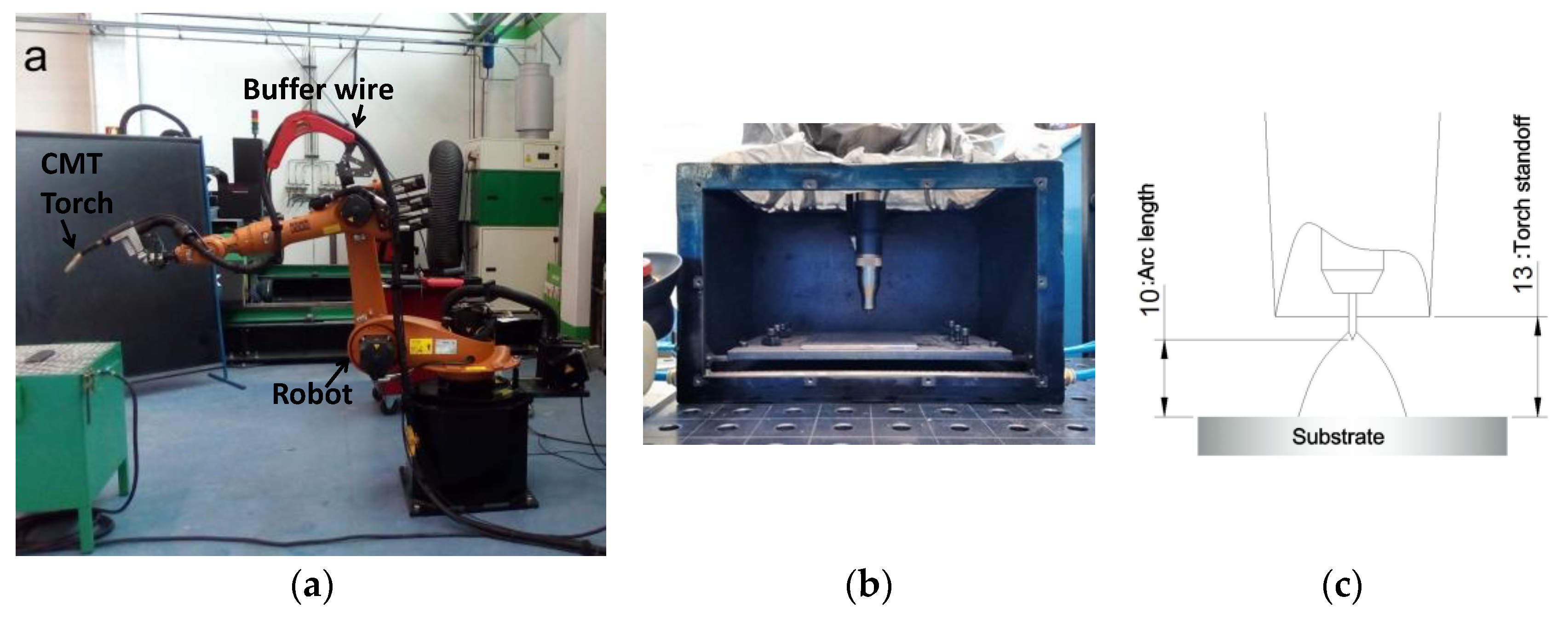
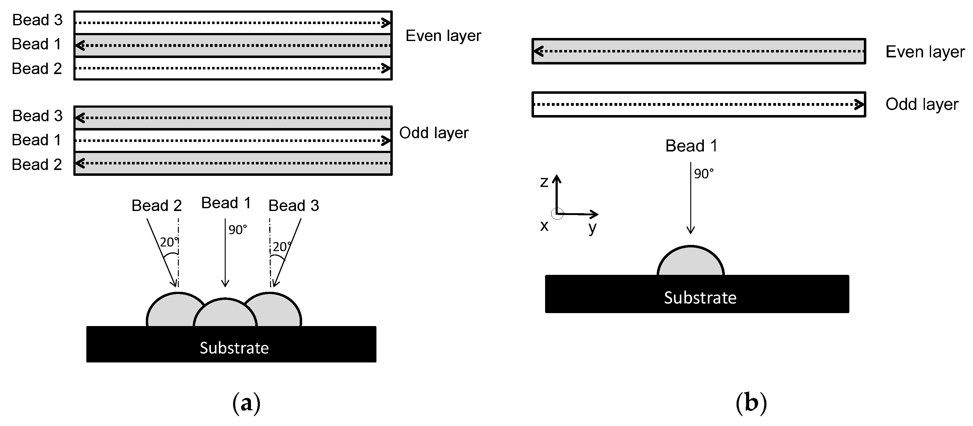
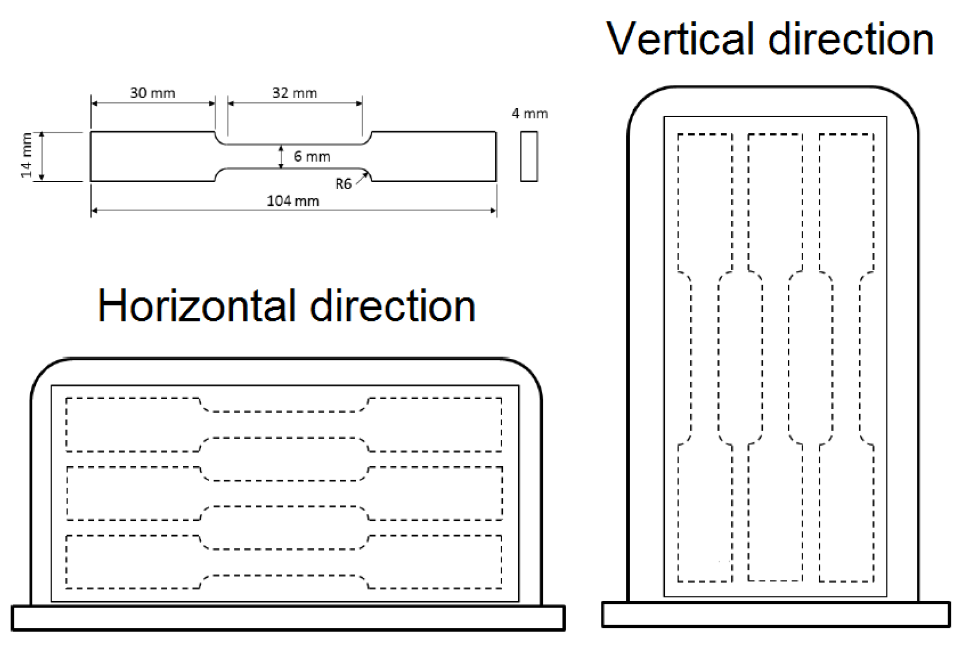
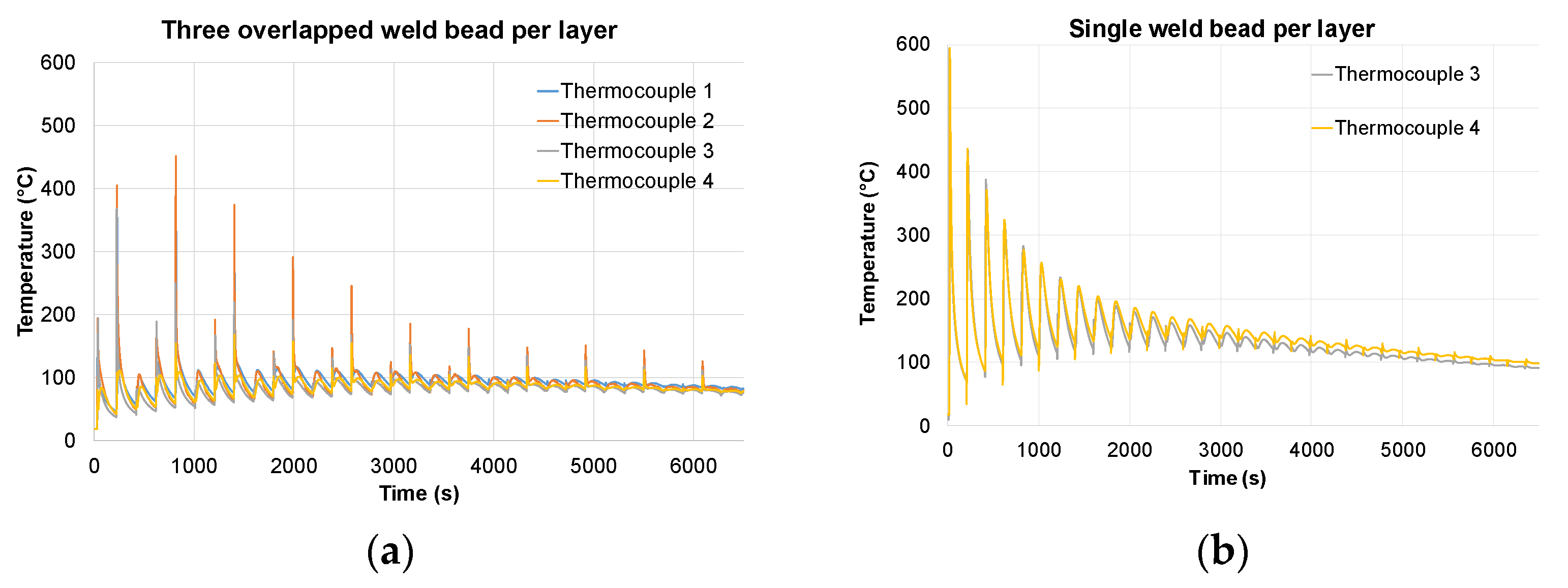
2. Materials and Methods

In this work, Ti-6Al-4V walls were manufactured by CMT, using a Fronius TransPuls synergic 4000 CMT R power source and Robacta Drive CMT WF +/− 6.25 mm torch from Fronius International, Wels, Austria. The torch was attached to a six-axis Kuka robot KR 16 KS model with a KRC2 controller, Kuka, Augsburg, Germany.
A mixture of Ar and He was employed as shielding gas in the torch. The gas flow was set at 16 L/min. With the aim of avoiding the oxidation of the walls during the manufacturing, all parts were manufactured in a closed chamber of 400 × 250 × 300 mm which was filled with Ar 99.9999% for a duration of 10 min. The gas flow inside the chamber was 17 L/min and it was maintained during the whole material deposition process. The setup and equipment can be observed in Figure 2. Welding parameters are included in Table 1. All these parameters were optimized in previous work where the procedure to obtain them is explained in detail [7]. The travel speed used for the single weld bead per layer strategy is 40 cm/min, and 50 cm/min for the three weld bead per layer strategy.
As filler metal, a wire of Ti-6Al-4V grade 5 with a diameter of 1.14 mm was used. The chemical composition obtained from Technalloy, Sant Cugat del Vallès, Spain the provider of the wire, is shown in Table 2. Substrates of the same alloy with equivalent chemical composition, obtained by hot rolling, with a 15 mm thickness were used for the manufacturing of the walls. These substrates were clamped during the deposition to a steel platform.
The strategy followed for the manufacturing of the walls, consisted in the deposition of a sequence of a pair of layers, as described in Figure 3, for both, thick and thin walls. Two different strategies were used for the manufacturing of these walls. One strategy consisted in the deposition of three overlapped weld beads per layer. The order of the deposition started with the deposition of the weld bead in the center, followed by the beads on the sides with the torch tilted 20° from the vertical. The overlapping used was 50% of the width of the weld bead (Figure 3a). The other strategy employed for the thin walls was based on the deposition of a single weld bead per layer (Figure 3b). In both cases the dwell time between the deposition of consecutive layers was 3 min. The direction of deposition of the weld beads in each layer and between superposed layers was alternated, in order to minimize the accumulation of material at the arc ignition and extinction zones, i.e., the start and end zones of the weld bead. In this way, an even and controlled growth of each layer was achieved, as is essential in the WAAM process.
Following the above-mentioned strategies, the manufactured walls were obtained as shown in Figure 4. The resulting wall thicknesses for both strategies are highlighted, i.e., 15 mm for the overlapped strategy and 8 mm for single weld bead strategy.
During the manufacture of the walls by both strategies, the temperature was recorded by contact thermocouples welded to the substrate. In Figure 5, four thermocouples of type K, attached to the substrate and very close to the wall are shown.
In order to verify the absence of defects inside the manufactured walls, non-destructive testing (NDT) was performed. X-Ray diffraction was applied following the UNE-EN ISO 17636 standard. All the walls tested in this study were free of defects like pores, cracks or lack of fusion above 0.2 mm size as shown in Figure 6.
WAAM parts were thermally treated at three different temperatures: 710 °C for 4 h, as conventional stress relieving heat treatment, and 850 °C and 920 °C for 5 h, all at high vacuum (<10−4 mbar). The temperature profiles are represented in Figure 7. Walls at the “as-built” stage were used as a reference to determine modification of mechanical properties and microstructure after heat treatments.
Once the manufactured walls were heat treated, three flat dog-bone tensile test specimens were extracted from thin and thick walls from horizontal (X) and vertical (Z) orientations, for both manufacturing strategies as represented in Figure 8, according to the ASTM E8M standard by using an electron discharge machine. Final thickness of the tensile test samples was 4 mm.
Tensile tests were performed in a model Z100 ZWICK/Roell testing machine, ZWICK/Roell, Ulm, Germany with a maximum load capacity of 100 kN. Specimens were tested at room temperature with a displacement rate of 1.6 mm/min and using an extensometer with a gauge length of 25 mm (Figure 9).
Advanced microstructural characterization was performed by field emission gun scanning electron microscopy (FEG-SEM) using a ZEISS Ultra Plus Field Emission, ZEISS, Overkochen, Germany), and by light microscopy using an Olympus GX 51, Olympus, Hamburg, Germany). Prior to characterization, parts were cut, mounted, grinded, polished and etched with Kroll reagent.

3. Results

This section includes the experimental results obtained for the two building strategies: three overlapped weld beads per layer and single weld bead per layer. In both cases, different heat treatments were applied in order to investigate their influence on the final mechanical properties and microstructure.

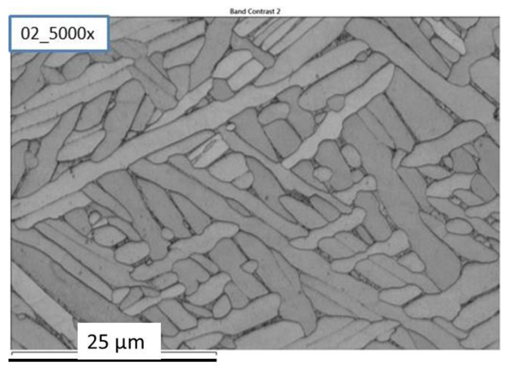
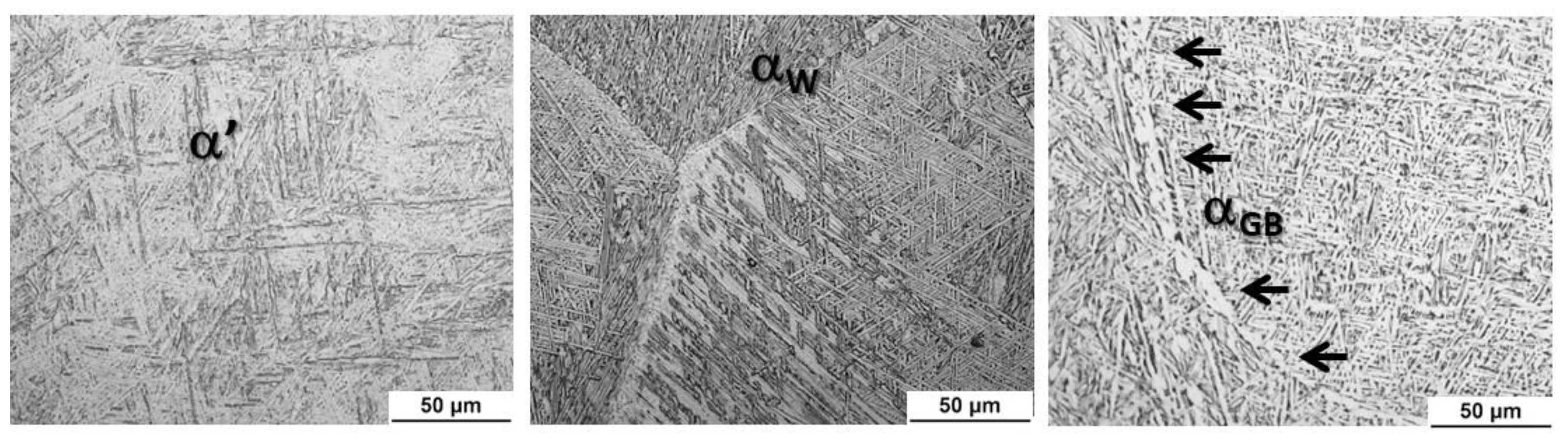
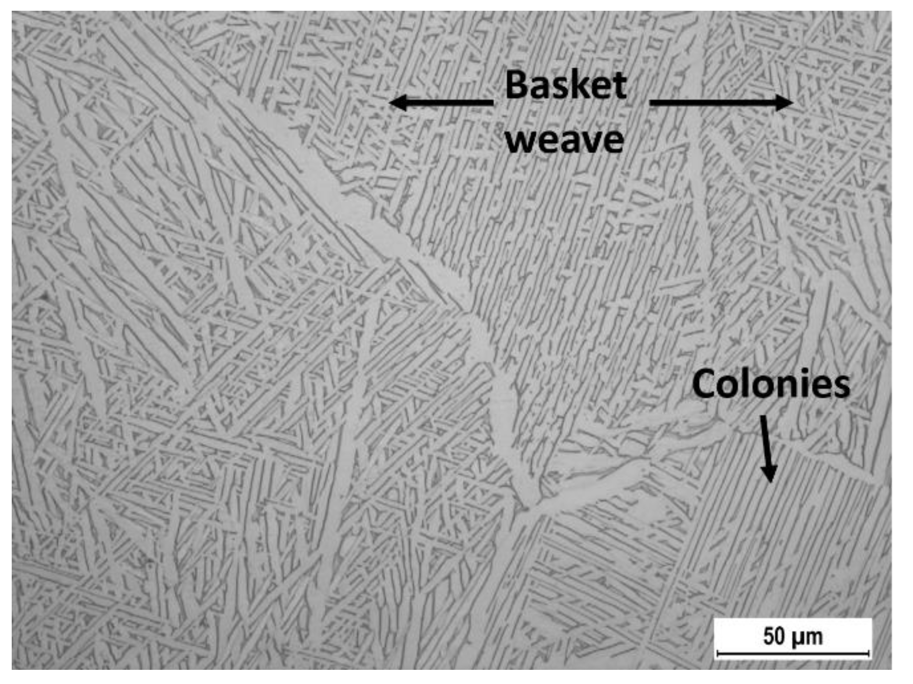
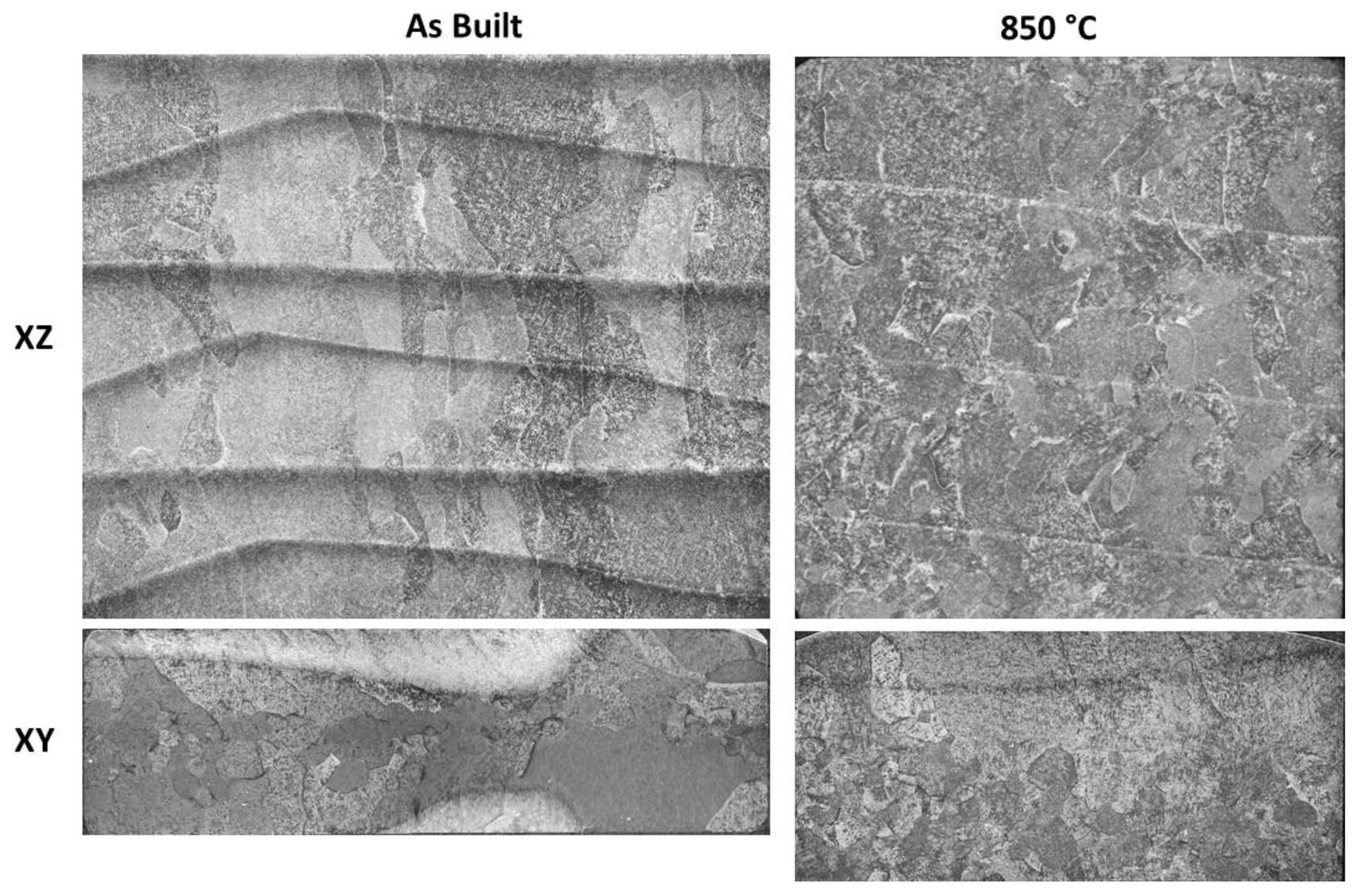
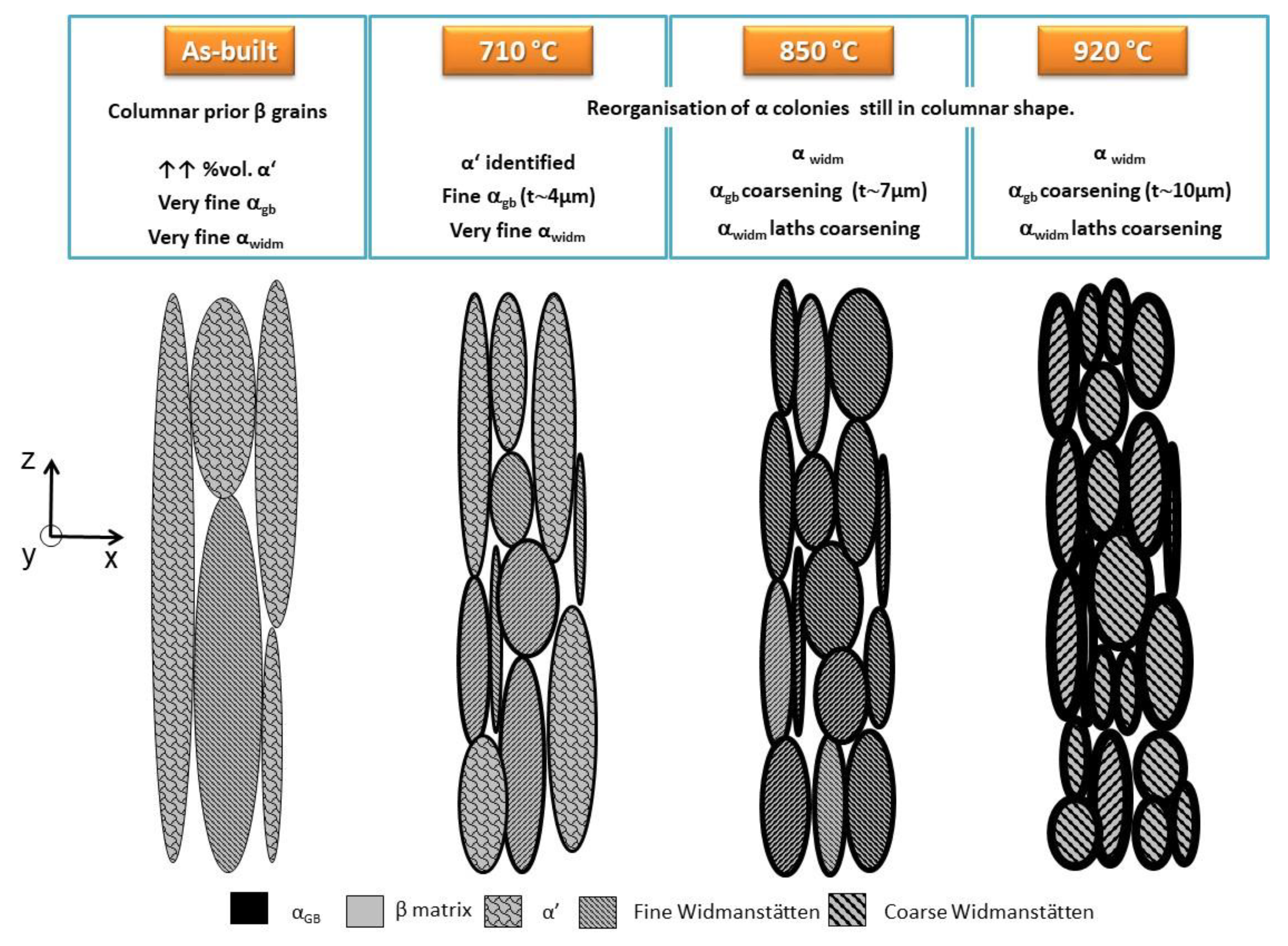
3.1. Microstructural Characterization

A detailed cross section of single- and three overlapped weld bead walls is shown in Figure 10. The elongated β grains in the growing direction can be clearly seen. In the case of the strategy of three overlapped weld beads, grain orientation is more complicated, due to a more complicated heat history.
In Figure 11, temperature profiles reveal the heat and cooling process in each deposited layer showing the repeated heating and cooling cycles. In the three overlapped weld bead strategy, each group of three peaks corresponds to one individual layer.
Regarding cooling rates at high temperature, the maximum calculated cooling rate from the temperature records of the solidification of the first deposited weld bead in the single weld bead strategy was 237 °C/s. At this cooling rate, the transformation from β phase is in a region known as competitive diffusionless and diffusional transformation [9]. However, this is a sum of weld beads deposited successively and the deposition of new weld beads is affected by the previous deposited ones. For this reason, heterogeneous microstructures were found.
Very similar microstructures were observed in both strategies. The different structures that can be found in this kind of microstructure are observed in the Figure 12. A needle like martensitic structure (α′) was observed in the higher part of each weld bead. Close to the martensitic zone, a fine lamella of α phase was found in a fine basket-weave form. In some of these parts, the α phase starts growing from the grain boundaries forming colonies. Finally, at the bottom of the weld bead, the α phase increases in the size of lamellae and in grain boundaries (highlighted by arrows). This complex microstructure is also observed in laser DED based additive manufacturing with Ti-6Al-4V [21].
This mixed structure is also appreciable due to the presence of basket weave Widmanstätten structure and colonies of α in the same grain as shown in Figure 13.
Figure 14 shows the effect of the application of thermal treatments on the microstructure. In the as-built, three weld bead per layer strategy sample, large columnar prior β grains oriented in the Z direction can be observed. After the application of heat treatment at 850 °C, a reorganization of phases was observed and the grains still exhibited a columnar shape. In the transversal section (XY), a reorganization of phases was also observed after the application of the heat treatment. In both, parallel bands corresponding to the thermal history due to the successive deposition of weld beads were observed.
The evolution of the microstructure with each treatment temperature, and at different magnifications, can be seen in detail by reference to Figure 15. In both strategies the microstructure was very heterogeneous and the observed evolution trend was very similar. In the as-built samples, martensitic structure was the dominant microstructure found. However, zones with very fine Widmanstätten α (αW) and very fine αGB could also be detected. After the heat treatment at 710 °C, corresponding to a stress relief treatment, martensitic structure could be still identified. Additionally, fine αGB was detected with an average thickness of 4 µm and a fine αW structure. After the application of the heat treatment at 850 °C, mainly αW was observed. Coarsening of the α lamellae and αGB was detected, in the last case with an average thickness of approximately 7 µm. No remaining α’ was found at this temperature [19]. Finally, with the heat treatment at 920 °C, greater coarsening of αW and αGB was detected, in the last case with an average thickness of 10 µm. At this temperature coarse Widmanstätten structure was observed.
The following presentation of the mechanical results is divided by the building strategy of the WAAM parts.

3.2. Mechanical Characterization of Three Overlapped Weld Beads per Layer WAAM Parts

Table 3 shows the mechanical properties obtained for the samples as-built, and after the applied heat treatments. Average values for the three samples and standard deviations are given. Mechanical properties were obtained for both directions: Z (vertical direction) and X (horizontal direction). The results revealed a continuous increase in the elongation and a corresponding decrease in strength for the higher heat treatment temperatures. Anisotropy was also appreciable with consistently higher strength and lower elongation in the horizontal direction, except for 710 °C treatment.

3.3. Mechanical Characterization of Single Weld Bead per Layer WAAM Parts

Table 4 shows the mechanical properties obtained for the samples as-built, and after the applied heat treatments. Mechanical properties were obtained for both directions: Z (vertical direction) and X (horizontal direction). Anisotropy was also appreciable in these samples. Obtained strength was higher in the vertical direction (Z)and elongation was also greater for vertical direction (Z). Furthermore, greater standard deviations were observed in most of the values. However, the results revealed a similar trend to the samples with three overlapped weld beads, with a continuous increase in elongation and a corresponding decrease in the strength for higher temperature treatments. Finally, strength values were lower and elongation values were higher compared to the three overlapped bead measurements.

4. Discussion

Regarding the microstructure in the as-built condition, the presence of large columnar prior β grains was found to be the typical macrostructure for Ti-6Al-4V WAAM parts in the XZ plane. The present phases observed inside these grains were mainly martensitic and fine αW. The size of these lamellae depends on the cooling rate from above the β transus temperature, the lamellae being thinner at higher cooling rates [22]. Metastable phases like α’ and α’’ are formed due to the rapid cooling of the material when deposited [22]. α’ is normally located at the layer in contact with the previously cooled layer and/or in the zones. This metastable phase presents smaller plate thickness and higher number of dislocations compared to α phase, being harder than α phase [22].
After a stress relief heat treatment at 710 °C, a reorganization of colonies was observed, however the prior β grains remained columnarly oriented. Microstructure after this heat treatment was still composed of α’ and fine αW. At higher temperatures (850 °C), the αW and αGB phases clearly coarsened. Colonies continue their reorganization. For the highest temperature applied in this work (920 °C), significant coarsening of α phase was detected. By this coarsening process, thicker αW lamellae and αGB are found. In all the cases, the treatment temperature was below the β transus temperature, which is 980 °C [22].
A schema explaining the evolution of the microstructure at different heat treatments has been developed in order to summarize the observed changes which have a direct impact on determined mechanical properties (Figure 16).
In the as-built samples, the anisotropy is attributed to columnar prior β grain morphology and the presence of αGB, which serves as a path along which damage can preferentially accumulate due to its lower ductility compared to the β phase, leading to fractures [22]. In the horizontal direction, a higher number of grain boundaries was observed, increasing the preferential damage zone. Anisotropic behavior has been reported by other authors in WAAM and other AM techniques [10,23]. The phases found were composed mainly of α’ and fine αW, which explains the low ductility obtained at this state.
After the application of heat treatment at 710 °C, the elongation was still low, however, the anisotropy was reduced. The results obtained comparing both directions do not follow the trends observed in the rest of the cases; higher elongation was observed in the longitudinal direction (X). This is a temperature used for stress relief and hence the values of elongation were not significantly improved, which is accordance with previous works [24]. At 850 °C, the mechanical property of elongation clearly increased, however, the strength decreased. This has previously been observed at similar temperatures [24]. At 920 °C, the best combination of mechanical properties was obtained, taking into account the specifications of the standards for this alloy. However, prior β grains still have an elongated shape in the vertical direction, and as a consequence, anisotropy remains.
Other work has shown [25] the trend associated with the growth of αW and its impact on increasing elongation. This was obtained after thermal treatment at 920 °C and a meandering strategy, and was attributed to the growth of αW and αGB making the whole structure more equilibrated, and hence the elimination of preferential paths. In the current work, we observed the same trend for the single weld bead and three overlapped weld bead samples, and we also observed the different steps followed by the phase evolution at different thermal treatments.
The thermal histories of the three overlapped and single weld bead strategies are different, and in the case of the three overlapped weld bead strategy, this thermal history is more complex than for the single weld bead strategy. The three overlapped weld bead wall was subjected to higher number of re-melting of previously deposited weld beads due to the overlapping itself. Moreover, the grains formed in the center might tend to grow diagonally creating a more complicated behavior (Figure 13). This is supposed to affect the organization of αW. In this way, different microstructures can be obtained, as explained in a work done employing laser metal deposition (LMD) [21], where different nucleation modes of αW were induced in walls with different thicknesses. For a slow cooling rate αW was mainly observed in a colony distribution with worse tensile properties, and for fast cooling rates αW was observed in a basket weave distribution with higher strength and ductility. Regarding the results, the values of ductility of the three overlapped weld bead walls were worse that the ones from the single weld bead walls. However, the values of strength were higher for the three overlapped weld bead strategy. This can be explained by the previously mentioned similarity in the microstructure found for both strategies. Mostly, mixed subgrain structures were found (Figure 13), with the same grain, colonies and basket weave Widmanstätten structures being visible.
In terms of yield strength and ultimate tensile strength, WAAM samples of the three overlapped weld bead strategy fulfil the most stringent standard (ASTM F1472 (wrought): YS > 860 MPa, UTS > 930 MPa) in all cases, i.e., as-built and after heat treatments. Taking into account the elongation, a minimum of 6% was obtained in the as-built condition, in line with AMS4985C (investment casting). After the heat treatment at 920 °C, in both orientations, and after 850 °C in one orientation, the elongation obtained was higher than 10% which fulfils the ASTM F1472 (wrought) standard. In the case of the single weld bead strategy, standard deviations were higher and the trend changed. The elongation continued to be higher for the vertical orientation, however, the strength was also higher. In all cases, this strategy fulfils the requirements of the standard ISO 5832-3 for wrought parts. These references are shown in Table 5.
Anisotropy was not fully removed at 920 °C (Table 6 and Table 7). The temperature of selected thermal treatments was below 980 °C which is below the β transus according to the Ti6Al4V phase diagrams. Due to this, the elongated shape of grains continued and hence the anisotropy of tensile properties. The anisotropy in elongation was generally lower in the case of the single weld bead strategy. It was also remarkable that the calculated anisotropy was higher after thermal treatments compared to the values obtained from the as-built samples. This is directly linked with the growth of αGB, which affects in higher amount in the horizontal orientation due to the larger number of grain boundaries, causing higher anisotropy. At the highest temperature (920 °C), this anisotropy decreased due to the compensation achieved by the growth of αGB and αW. Regarding the anisotropy in strength, it was higher for the single weld bead than for the three overlapped weld bead strategy. It is also remarkable that no substantial differences were observed after the application of heat treatments. This can be explained because of the presence of elongated grains after the heat treatments.
Comparing the results obtained for three overlapped weld beads and single weld bead based walls, the parts composed of single weld beads obtained higher elongation values and lower anisotropy. Regarding strength values, the three overlapped weld bead strategy obtained higher values and the anisotropy was lower than in the case of the single weld bead strategy. However, taking into account the reference values defined in the standards, the results of the single weld bead strategy fulfill the most restrictive ones at 850 °C, and for the three overlapped weld bead strategy, at 920 °C. This difference can be explained due to the increase in complexity of thermal history leading to complex microstructures caused by the horizontal overlapping of weld beads. In order to achieve high elongation values, it is not necessary to exceed the β transus temperature

5. Conclusions

Defect-free and sound Ti-6Al-4V walls were manufactured by a CMT-based WAAM process with a deposition rate of 2.3 kg/h. Different deposition strategies were successfully applied to achieve flat and uniform walls, i.e., overlapping three parallel weld beads, or alternatively, depositing single weld beads.
An appropriate selection of post-deposition heat treatments was performed to increase the ductility of the as-built walls to fulfil the most demanding industrial standards applied to wrought components. Regarding the anisotropy, heat treatments below 980 °C were not able to reduce it, however, low values of anisotropy in elongation (7%) were obtained in the single weld bead strategy whereas a value of 20% was obtained in the three overlapped weld bead strategy due to the more complex microstructure. Strength was reduced with the application of heat treatments, however, a good balance of tensile properties was obtained. Anisotropy in strength was low for both strategies, being lower in the three overlapped weld bead strategy.
Heat treatment at 920 °C applied to single weld bead-based walls increased elongation by around 70%, while yield strength and ultimate tensile strength reductions were maintained below 8% compared to the as-built samples. Despite the anisotropy in elongation being maintained at the same value (7% in the case of single weld bead strategy) or increased slightly (by 5% in the case of three overlapped weld bead strategy), this heat treatment has clearly demonstrated to be the most appropriate one for the improvement of overall mechanical properties.

Author Contributions

Conceptualization, L.V. and P.A.; methodology, L.V. and I.R.; validation, P.A.; formal analysis, L.V., M.N.R. and P.A.; investigation, L.V. and I.R.; resources, P.A.; data curation, L.V. and M.N.R.; writing—original draft preparation, L.V.; writing—review and editing, M.N.R. and P.A.; supervision, P.A.; funding acquisition, P.A. All authors have read and agreed to the published version of the manuscript.

Funding

This research was supported of Ministry of Science and innovation of the Spanish Government through the program “Ayudas destinadas a centros tecnológicos de excelencia CERVERA 438 año 2019” from CDTI (Centro para el Desarrollo Tecnológico Industrial) in the frame of the CEFAM 439 Project, grant CER-20191005.

Institutional Review Board Statement

Not applicable.

Informed Consent Statement

Not applicable.

Data Availability Statement

Data available on request due to restrictions. The data presented in this study are available from the corresponding author.

Conflicts of Interest

The authors declare no conflict of interest.

References

  1. Baufeld, B.; Van der Biest, O.; Gault, R. Additive manufacturing of Ti-6Al-4V components by shaped metal deposition: Microstructure and mechanical properties. Mater. Des. 2010, 31, S106–S111. [Google Scholar] [CrossRef]
  2. McAndrew, A.R.; Alvarez Rosales, M.; Colegrove, P.A.; Hönnige, J.R.; Ho, A.; Fayolle, R.; Eyitayo, K.; Stan, I.; Sukrongpang, P.; Crochemore, A.; et al. Interpass rolling of Ti-6Al-4V WAAM features for microstructural refinement. Addit. Manuf. 2018, 21, 340–349. [Google Scholar] [CrossRef]
  3. Ding, D.; Pan, Z.; Cuiuri, D.; Li, H. A multi-bead overlapping model for robotic wire and arc additive manufacturing (WAAM). Robot. Comput. Integr. Manuf. 2015, 31, 101–110. [Google Scholar] [CrossRef] [Green Version]
  4. Ding, D.; Pan, Z.; Cuiuri, D.; Li, H. Wire-feed additive manufacturing of metal components: Technologies, developments and future interests. Int. J. Adv. Manuf. Technol. 2015, 81, 465–481. [Google Scholar] [CrossRef]
  5. Gefertec GmbH. Available online: http://www.gefertec.com/ (accessed on 8 May 2018).
  6. Sequeira Almeida, P.M.; Williams, S. Innovative process model of Ti-6Al-4V additive layer manufacturing using cold metal transfer (CMT). In Proceedings of the 21st Annual International Solid Freeform Fabrication Symposium, Austin, TX, USA, 9–11 August 2010; pp. 25–36. [Google Scholar]
  7. Rodriguez, N.; Vázquez, L.; Huarte, I.; Arruti, E.; Tabernero, I.; Alvarez, P. Wire and Arc Additive Manufacturing: A comparison between CMT and TopTIG processes applied to Stainless Steel. Weld. World 2018, 62. [Google Scholar] [CrossRef]
  8. Wang, F.; Williams, S.; Colegrove, P.; Antonysamy, A.A. Microstructure and mechanical properties of wire and arc additive manufactured Ti-6Al-4V. Metall. Mater. Trans. A 2013, 44, 10. [Google Scholar] [CrossRef]
  9. Antonysamy, A.A. Microstructure, Texture and Mechanical Property Evolution during Additive Manufacturing of Ti6Al4V Alloy for Aerospace Applications. Ph.D. Thesis, University of Manchester, Manchester, UK, 2012. [Google Scholar]
  10. Xie, Y.; Gao, M.; Wang, F.; Zhang, C.; Hao, K.; Wang, H.; Zeng, X. Anisotropy of fatigue crack growth in wire arc additive manufactured Ti-6Al-4V. Mater. Sci. Eng. A 2018, 709, 265–269. [Google Scholar] [CrossRef]
  11. Donoghue, J.; Antonysamy, A.A.; Martina, F.; Colegrove, P.A.; Williams, S.W.; Prangnell, P.B. The effectiveness of combining rolling deformation with Wire-Arc Additive Manufacture on β-grain refinement and texture modification in Ti-6Al-4V. Mater. Charact. 2016, 114, 103–114. [Google Scholar] [CrossRef]
  12. Hönnige, J.R.; Davis, A.E.; Ho, A.; Kennedy, J.R.; Neto, L.; Prangnell, P.B.; Williams, S. The Effectiveness of Grain Refinement by Machine Hammer Peening in High Deposition Rate Wire-Arc AM Ti-6Al-4V. Metall. Mater. Trans. A. 2020, 51, 3692–3703. [Google Scholar] [CrossRef]
  13. Colegrove, P.A.; Donoghue, J.; Martina, F.; Gu, J.; Prangnell, P.; Hönnige, J. Application of bulk deformation methods for microstructural and material property improvement and residual stress and distortion control in additively manufactured components. Scr. Mater. 2017, 135, 111–118. [Google Scholar] [CrossRef]
  14. Hönnige, J.; Colegrove, P.A.; Fitzpatrick, M.E.; Ganguly, S.; Lee, T.; Williams, S. Residual stress and texture control in Ti-6Al-4V wire + arc additively manufactured intersections by stress relief and rolling. Mater. Des. 2018, 150, 14. [Google Scholar] [CrossRef] [Green Version]
  15. Ding, J.; Colegrove, P.A.; Mehnen, J.; Ganguly, S.; Sequeira Almeida, P.M.; Wang, F.; Williams, S. Thermo-mechanical analysis of Wire and Arc Additive Layer Manufacturing process on large multi-layer parts. Comput. Mater. Sci. 2011, 50, 3315–3322. [Google Scholar] [CrossRef] [Green Version]
  16. Brandl, E.; Greitemeier, D. Microstructure of additive layer manufactured Ti-6Al-4V after exceptional post heat treatments. Mater. Lett. 2012, 81, 84–87. [Google Scholar] [CrossRef]
  17. Prado-Cerqueiram, J.L.; Camacho, A.M.; Diéguez, J.L.; Rodríguez-Prieto, A.; Aragón, A.M.; Lorenzo-Martín, C.; Yanguas-Gil, A. Analysis of Favorable Process Conditions for the Manufacturing of Thin-Wall Pieces of Mild Steel Obtained by Wire and Arc Additive Manufacturing (WAAM). Materials 2018, 11, 1449. [Google Scholar] [CrossRef] [PubMed] [Green Version]
  18. Montero Sistiaga, M.L.; Nardone, S.; Hautfenne, C.; van Humbeeck, A. Effect of Heat Treatment of 316L Stainless Steel Produced by Selective Laser Melting (SLM). In Proceedings of the 27th Annual International Solid Freeform Fabrication Symposium, Austin, TX, USA, 10–12 August 2016; p. 8. [Google Scholar]
  19. Gou, J.; Shen, J.; Hu, S.; Tian, Y.; Liang, Y. Microstructure and mechanical properties of as-built and heat-treated Ti-6Al-4V alloy prepared by cold metal transfer additive manufacturing. J. Manuf. Process. 2019, 42, 41–50. [Google Scholar] [CrossRef]
  20. Bermingham, M.J.; Nicastro, L.; Kent, D.; Chen, Y.; Dargusch, M.S. Optimising the mechanical properties of Ti-6Al-4V components produced by wire + arc additive manufacturing with post-process heat treatments. J. Alloys Compd. 2018, 753, 247–255. [Google Scholar] [CrossRef]
  21. Zhao, Z.; Chen, J.; Lu, X.; Tan, H.; Lin, X.; Huang, W. Formation mechanism of the α variant and its influence on the tensile properties of laser solid formed Ti-6Al-4V titanium alloy. Mater. Sci. Eng. A 2019, 691, 16–24. [Google Scholar] [CrossRef]
  22. Babu, B. Physically Based Model for Plasticity and Creep of Ti-6Al-4V. Ph.D. Thesis, Luleå University of Technology, Luleå, Sweden, 2008. [Google Scholar]
  23. Carroll, B.E.; Palmer, T.A.; Beese, A.M. Anisotropic tensile behavior of Ti-6Al-4V components fabricated with directed energy deposition additive manufacturing. Acta Mater. 2015, 87, 309–320. [Google Scholar] [CrossRef]
  24. Brandl, E.; Baufeld, B.; Leyens, C.; Gault, R. Additive manufactured Ti-6Al-4V using welding wire: Comparison of laser and arc beam deposition and evaluation with respect to aerospace material specifications. Phys. Procedia 2010, 5, 595–606. [Google Scholar] [CrossRef] [Green Version]
  25. Vázquez, L.; Rodríguez, N.; Rodríguez, I.; Alberdi, E.; Álvarez, P. Influence of interpass cooling conditions on microstructure and tensile properties of Ti-6Al-4V parts manufactured by WAAM. Weld. World 2020, 64, 1377–1388. [Google Scholar] [CrossRef]
Figure 1. Microsctructure of Ti-6Al-4V showing α lamellae inmersed in β matrix.
Metals 11 01161 g001
Figure 2. Set up for WAAM (wire and arc additive manufacturing) process: (a) CMT (cold metal transfer) torch attached to 6-axis robot, (b) chamber for protective atmosphere, (c) scheme of the torch.
Metals 11 01161 g002
Figure 3. Build strategy followed for WAAM walls: (a) Three overlapped weld beads per layer applied to thick walls, (b) single weld bead per layer used for thin ones.
Metals 11 01161 g003
Figure 4. Manufactured WAAM walls: (a) Three weld beads per layer strategy, (b) single weld bead per layer strategy.
Metals 11 01161 g004
Figure 5. (a) Thermocouples attached to the substrate for temperature recording during the manufacturing of the walls and (b) a schema of their position in the substrate. T1: thermocouple 1, T2: thermocouple 2, T3: thermocouple 3, T4: thermocouple 4.
Metals 11 01161 g005
Figure 6. X-ray photo showing the absence of defects in manufactured wall.
Metals 11 01161 g006
Figure 7. Recorded temperature profiles of thermal treatments.
Metals 11 01161 g007
Figure 8. Scheme of the specimens for tensile test extracted from different orientations.
Metals 11 01161 g008
Figure 9. Tensile specimens: (a) extracted tensile test specimens for tensile testing and (b) a specimen in the testing machine.
Metals 11 01161 g009
Figure 10. Cross section of walls: (a) single weld bead strategy wall, (b) three overlapped weld beads strategy wall.
Metals 11 01161 g010
Figure 11. Temperature records for (a) three overlapped weld beads strategy wall and (b) single weld bead strategy wall.
Metals 11 01161 g011
Figure 12. Heterogeneity of microstructures detected in different zones of the weld beads (α’: martensite, αW: Widmanstätten α phase, αGB: α phase in the grain boundary).
Metals 11 01161 g012
Figure 13. Different Widmanstätten structures found in Ti6Al4V.
Metals 11 01161 g013
Figure 14. Microstructure observed for the as-built sample, and after the application of a heat treatment at 850 °C in XZ: vertical plane and XY: horizontal plane.
Metals 11 01161 g014
Figure 15. Evolution of the microstructures in the as-built state and after the application of the three different thermal treatments. In the columns, microstructures at different magnifications are shown (α’: martensite, αW: Widmanstätten α phase, αGB: α phase in the grain boundary).
Metals 11 01161 g015
Figure 16. Schema of the evolution of the microstructure of Ti-6Al-4V WAAM samples as-built, and after the application of different heat treatments.
Metals 11 01161 g016
Table 1. CMT (cold metal transfer) welding parameters for parts manufacturing.
ModeCurrent (A)Wire Feed Speed (m/min)Voltage (V)Travel Speed (cm/min)Arc Length (mm)
Continuous1408.515.840/5010
Table 2. Chemical composition given by the provider of Ti-6Al-4V grade 5 wire (wt.%).
Filler WireAlVTiFeCONHYOther
Ti-6Al-4V grade 56.264.17Balance0.150.0240.140.0060.0030.002<0.2
Table 3. Mechanical properties (Rp0.2: yield strength, Rm: ultimate tensile strength, e: elongation) achieved for both orientations for WAAM parts treated at different temperatures.
Temperature of
Thermal Treatment
OrientationRp0.2 (MPa)Rm (MPa)e (%)
As builtZ946.9 ± 8.11038.5 ± 8.38.2 ± 1.4
X958.8 ± 3.41046.1 ± 3.26.1 ± 0.7
710 °CZ970.5 ± 4.21027.3 ± 5.15.5 ± 0.9
X967.2 ± 7.61030.2 ± 9.25.8 ± 0.6
850 °CZ902.9 ± 5.0989.1 ± 4.411.2 ± 0.9
X922.5 ± 1.01005.0 ± 2.26.1 ± 0.3
920 °CZ859.7 ± 2.6973.1 ± 2.715.8 ± 1.3
X880.5 ± 3.9981.0 ± 6.510.6 ± 1.8
Table 4. Mechanical properties (Rp0.2: yield strength, Rm: ultimate tensile strength, e: elongation) achieved for both orientations for WAAM parts treated at different temperatures.
Temperature of
Thermal Treatment
OrientationRp0.2 (MPa)Rm (MPa)e (%)
As-builtZ917.5 ± 8.11007.0 ± 4.79.4 ± 5.6
X884.9 ± 10.3986.0 ± 13.28.2 ± 2.0
850 °CZ911.6 ± 11.1994.5 ± 13.914.3 ± 1.6
X866.9 ± 4.8948.8 ± 3.511.1 ± 0.8
920 °CZ855.2 ± 9.5968.7 ± 10.617.5 ± 1.1
X809.8 ± 12.2919.4 ± 5.015.2 ± 1.5
Table 5. Standards for casting and wrought parts for Ti6Al4V regarding tensile properties.
ReferenceRp0.2 (MPa)Rm (MPa)e (%)
AMS 4985C-2003 (investment casting)>827>896>6
ISO 5832-3 (wrought)>780>860>10
ASTM F1108 (casting)>758>860>8
ASTM F1472 (wrought)>860>930>10
Table 6. Anisotropy of tensile properties calculated for three overlapped weld bead strategy after each thermal treatment.
Temperature of Thermal TreatmentAnisotropy (%)
Rp0.2 (MPa)Rm (MPa)e (%)
AB1015
710 °C003
850 °C1129
920 °C1020
Table 7. Anisotropy of tensile properties calculated for single weld bead strategy after each thermal treatment.
Temperature of Thermal TreatmentAnisotropy (%)
Rp0.2 (MPa)Rm (MPa)e (%)
AB217
850 °C3213
920 °C237
Publisher’s Note: MDPI stays neutral with regard to jurisdictional claims in published maps and institutional affiliations.

