Abstract
The results of investigating the structure and properties of multilayered bimetallic “steel–copper” macrocomposite systems, obtained by wire-feed electron beam additive manufacturing, are presented in the paper. The features of boundary formation during 3D printing are revealed when changing the filaments of stainless steel and copper. Inhomogeneities in the distribution of steel and copper in the boundary zone were detected. Interphase interaction occurs both in the steel and copper parts of the structural boundary: Cu particles with an average size of 5 µm are formed in the iron matrix; Fe particles with an average size of 10 µm are formed in the copper matrix. It was revealed that such structural elements, as solid solutions of both copper and iron, are formed in the boundary zone, with additional mutual dissolution of alloying elements and mechanical mixtures of system components. The presence of the disc-shaped precipitations randomly located in the matrix was revealed in the structure of the “copper–steel” boundary by transmission electron microscopy; this is associated with rapid cooling of alloys and the subsequent thermal effect at lower temperatures during the application of subsequent layers. The existence of these disc-shaped precipitations of steel, arranged randomly in the Cu matrix, allows us to draw conclusions on the spinodal decomposition of alloying elements of steel. The characteristics of mechanical and micromechanical properties of a bimetallic multilayered composite with a complex formed structure lie in the range of characteristics inherent in additive steel and additive copper.
1. Introduction
The technology of obtaining polymetallic materials has been widely studied in the last decade. Polymetallic materials are made using two or more metals or alloys. These materials are designed to provide an optimal combination of physical, mechanical and chemical properties unattainable with any of their individual components. As has been described [1], high thermal conductivity, strength and corrosion resistance are essential for materials used in electricity generation and its transportation processes. Currently, many technical and industrial problems cannot be solved using only single materials based on one metal or alloy (monometallic materials). This is due to the fact that in these operating conditions the material must have a high rate of heat transfer with minimal thermal losses, as well as resist any form of corrosion in the working environment. As a compromise, a heterogeneous combination of materials can be used, where one superior property can be provided locally in the structure, while at the same time using the advantages of the primary material elsewhere. As proposed [2] in addition to this, the emerging requirements for lightweight structures with optimized and variable characteristics and functionality have increased the scope of applications for multilayer structures. This necessitates the coupling of materials with different physical/thermal properties.
Multilayered composites are widely used in many industries, such as the military, automotive and aerospace industries due to their outstanding mechanical properties, as previously described [3]. Multilayered composites can consist of different types of layers, such as ceramic/metal, metal/metal, metal/composite or ceramic/composite. The most common metals and alloys, such as steel, cast iron, copper, aluminum and magnesium alloys, can be used to prepare polymetallic metal/metal composites [4]. Plasma spraying [5], pressing [6], welding [7] and friction stir welding [8] are used to produce polymetallic materials. However, the quality of polymetals using such methods directly depends on the quality of the polymetallic plate’s weld. Heterogeneous materials should form a strong connection with each other without internal cavities and cracks, because due to discontinuities, the polymetallic product loses the required values of performance properties. This has led to even greater interest in additive manufacturing (AM). AM methods, such as electron beam 3D printing, can provide spatial process control directly during 3D printing of the product and reduce the production process, compared to conventional methods of product manufacturing. Distinctive features of electron beam 3D printing are: the combination of wire technology and a vacuum chamber with an electron beam significantly reduces the cost of printing, an increase in the productivity of the process, high physical and mechanical properties and reducing the possibility of defect formation in the printed products.
The combination of different mechanical and physical–chemical properties implies not only a multifunctional finished product, but also the complexity and, in some cases, the impossibility, of combining metals and alloys. One such example discussed in this study is the combination of C11000 copper and SS 321 stainless steel. Copper has a face-centered cubic (FCC) crystal lattice and has high thermal conductivity characteristics, but has less corrosion resistance compared to stainless steel. Thus, products based on copper have many applications in electrical engineering due to their high characteristics and excellent formability. Usually, stainless steels have been used as structural materials in the nuclear, petrochemical and chemical industries because of their excellent corrosion resistance, but they do not conduct heat as well as copper. Copper (Cu)–stainless steel (SS) compounds are required in the nuclear power industry as an important component of vacuum chambers for particle accelerators [9], and in cryogenics [10], providing the high electrical conductivity of copper and high mechanical strength of steel. To combine the advantages of stainless steel with copper, a suitable welding process must be applied. However, the large differences in the properties of Cu and SS, such as melting temperature (Cu: 1085 °C, SS: 1400–1500 °C) and thermal conductivity (Cu: 401 W/mK, SS: 17–19 W/mK) make the joining task more difficult for any fusion welding processes, and the formation of intermetallic compounds when joining Cu alloys to other materials may also occur [11]. As has been shown [12], copper penetration along the heat-affected zone (HAZ) of steel can lead to hot cracking because copper has very limited solubility with steel in the liquid state. Meanwhile, the Fe–Cu phase diagram does not contain intermetallic phases except for a small region of limited solubility between Cu and Fe. The significant difference in thermal expansion and thermal conductivity coefficients for copper and steel inevitably causes large deformation and residual stresses when the material cools from the melting temperature, which leads to cracking during solidification of bimetallic samples. Hydrogen readily dissolves in liquid copper and promotes pore formation in the bimetallic junction area [12]. Liquid-phase separation between Cu and Fe is commonly observed in laser, electron beam and arc welding processes [13]. In this case, the presence of liquid-phase separation leads to the formation of pores and cracks, which negatively affects the mechanical properties of the finished product. It is known that the layer bonding in printed samples results in weaker parts than what is found in the bulk material and that print settings and raster orientation can affect the material characteristics [14].
The literature contains a number of studies on copper/steel welding using different methods, such as diffusion welding [15], radial friction welding [16], inert gas arc welding with a non-consumable tungsten electrode [17], electron beam welding (EBW) [18], laser welding (LBW) [19], explosion welding [20] and friction stir welding processes [21], hot-pressing [22], the selective laser welding method [23] and the laser direct deposition method [24]. Magnabosco et al. [18] demonstrated the presence of defects such as voids in electron beam welding of copper with austenitic stainless steels. Chen et al. [19] observed cracks in a stainless steel/copper disc, in a similar joint made by laser welding. However, it is clear that all high-energy fusion welding processes (EBW, LBW) suffer from major drawbacks, and more experimental difficulties are associated with solid-state welding processes for the Cu–SS system joint. As demonstrated, there are few works on studying the properties of copper–steel bimetals made by additive manufacturing methods. Shu et al. [25] describe bimetallic samples fabricated by selective laser melting (SLM) and consisting of 316L stainless steel and C18400 copper alloy. These steel and copper samples had a developed stainless steel/copper interface, but the transition zone was quite narrow and porous, which affected the mechanical properties of these bimetallic samples. Tan et al. [12] were able to partially avoid the previously mentioned problems by using SLM AT to form a bimetallic martensitic steel sample. Good metallurgical contacts at the interface between martensitic copper steels and copper were obtained and an interfacial bonding mechanism was proposed. Imran et al. [24] demonstrated that H13 tool steel is successfully deposited on a copper substrate by laser direct metal deposition. No cracks or pores were observed at the interfaces of this material, but tensile cracks were formed in the heat-affected zones or joints. The electron beam free form fabrication (EBF3) method was used to produce bimetallic samples by depositing two layers of AISI 304 wire and then T2 copper wire [12]. The presence of dendrites and spherical Fe-particles in copper-rich areas was shown, as well as cracks at the copper/steel interface. As has been shown [26], bimetal-based C11000 and SS 304 were fabricated by electron beam additive manufacturing with simultaneous feeding of two wires. In the present work, a bimetallic multilayered composite “stainless steel/copper” was fabricated by wire-feed electron beam additive manufacturing to study the regularities of the formation of the steel–copper and copper–steel transition zone. Investigations are connected with the phenomena which occur during solidification from the liquid and solid-phase transformations.
2. Materials and Methods
The samples were obtained in an experimental facility for additive electron beam fabrication of metal products. AISI 321 stainless steel wire and C11000 copper wire were used for 3D printing of the samples (Table 1). The diameter of the steel wire was 1.2 mm and the diameter of the copper wire was 1 mm. The nominal chemical composition of the materials is shown in Table 1.

Table 1.
Chemical composition of the substrate and filaments used in the wire-feed electron beam additive manufacturing.
The steel substrate was fixed on a three-axis water-cooled table. An electron beam was used to form a molten pool. A wire was fed into the molten pool and the vertical wall was 3D printed by layer-by-layer deposition of the material. The building direction was perpendicular to the table surface. An alternating strategy of depositing heterogeneous wires was chosen to manufacture the vertical wall. The printing parameters of manufacturing the vertical wall are shown in Table 2.
Table 2.
The 3D printing parameters for manufacturing the vertical wall from dissimilar materials based on steel and copper.
A multilayered macrocomposite was formed on a rectangular 4.5 mm thick AISI 304 steel substrate. First, 5 layers of SS 321 steel were deposited onto the substrate; after the 5th layer had been deposited, the steel wire feed was stopped. Then, 5 layers of C11000 copper were deposited on the formed layers of steel and, after the deposition of the 5th layer was completed, the feeding of the copper wire was stopped. Then, the application of 5 layers of steel on the previously deposited layers of copper and deposition of copper on the previously deposited steel layers were repeated. After the “vertical wall” building process was completed, the last 5 steel layers were deposited. Thus, the finished multilayered macrocomposite was a “wall” with alternating interlayers of SS–Cu–SS–Cu–SS with length ≈ 100 mm, thickness ≈ 5 mm and height 30 mm.
From the vertical walls grown according to the scheme of Figure 1, samples were cut out with a DK7750 electrical discharge machine (Suzhou Longkai Electromechanical Technology Co., Ltd., Suzhou, China) to study the macro- and microstructure, and mechanical and thermophysical properties.
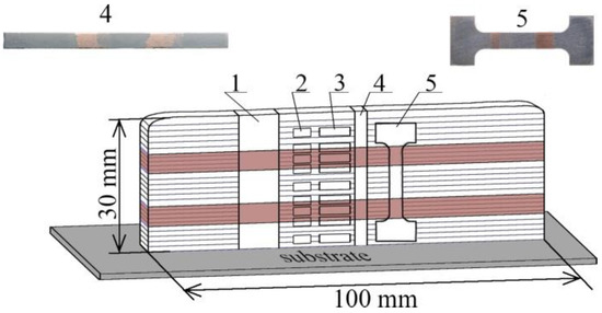
Figure 1.
Scheme of cutting samples for research: 1—samples for macrostructural studies, measurement of microhardness and elemental composition; 2—areas for transmission electron microscopy; 3—areas for X-ray diffraction analysis; 4—areas for measurement of thermal linear expansion coefficient; 5—samples in the form of double blades for mechanical tensile tests.
Samples for macrostructural studies were cut in the longitudinal direction relative to the cladding layer and had dimensions of 30 mm in height and 10 mm in width. Metallographic studies of the structure of the samples were carried out using an OLYMPUS LEXT confocal microscope (Olympus NDT, Inc., Waltham, MA, USA). Microhardness was measured on the same samples by the Vickers method on a Duramin-5 (Struers A/S, Ballerup, Denmark) at a load of 50 g for 10 s. Along the indentation traces, the elemental composition of the bimetallic layered macrocomposite of the samples was analyzed using a Zeiss LEO EVO 50 scanning electron microscope (Carl Zeiss, Oberkochen, Germany), with an energy dispersive elemental microanalysis attachment. After mechanical tensile testing, the fractographic analysis was performed using a scanning electron microscope. A tensile sample with a working part size of 12 × 1.5 × 2.7 mm3 was used to study the mechanical characteristics. The tests were performed on a UTS 110M universal testing machine (Testsystems, Ivanovo, Russia). The strain rate was 1.4 × 10⁻³ s−1. A JEOL JEM-2100 transmission electron microscope (JEOL Ltd., Akishima, Japan) was used for microstructural studies. Disc plates with a diameter of 3 mm and a thickness of 300 μm were cut from area 2 (Figure 1). The discs were thinned to the first hole in the central part of the sample for transmission electron microscopy (TEM) using the Micron-M facility by single-sided jet electrolytic polishing. X-ray structural analysis was performed on an X-ray diffractometer (DRON-7, Innovation center “Burevestnik”, St. Petersburg, Russia) using CoKα radiation at 0.05° increments and an exposure time of 10 s per step. A DIL 402 PC/4 dilatometer (Netzsch-Gerätebau GmbH, Selb, Germany) was used to measure the coefficient of thermal linear expansion (CTE). Samples for the LET measurement had the following dimensions: steel, 1.63 × 1.94 × 24.77 mm3; copper, 1.82 × 1.72 × 24.91 mm3; and polymetal, 1.85 × 1.71 × 24.92 mm3. The samples were heated to between 20 and 600 °C. The samples in the form of rectangular parallelepipeds were cut in the direction of the polymetallic sample growth (Figure 1, position 4).
3. Results
3.1. Selection of Parameters
The appearance of vertical walls grown by electron beam additive manufacturing using filaments of heterogeneous materials of steel (SS) and copper (Cu) is shown in Figure 2.
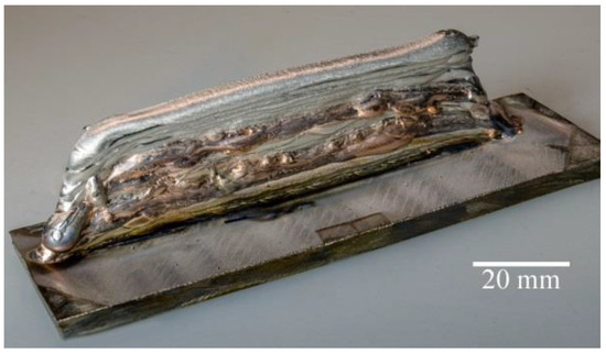
Figure 2.
Vertical walls of “SS–Cu–SS–Cu–SS” were manufactured using copper and steel wires by the method of electron beam additive manufacturing.
During the melting of fed wire by the electron beam with the formation of a molten pool, there is a local increase in the substrate temperature near the molten pool. As a result, a temperature gradient occurs, which leads to the presence of internal stresses. After a number of thermal cycles, the substrate deforms under the influence of temperature stresses.
In the course of growing the vertical wall, macrodefects are formed. This occurs due to insufficient heating or overheating of the fed filament, which entails a difference in the size of the formed layer. In the case of overheating, material spreads, droplets are formed and the shape of the vertical wall is distorted across the width. In the case of insufficient heating, unmelted parts of the wire remain, which leads to non-melting of the first layers with the substrate and layers with each other, and pores are formed in the areas not filled with unmelted filament. In the present work, these factors were taken into account, and optimal parameters were selected for vertical wall printing from heterogeneous materials in order to avoid the influence of insufficient heating or overheating. This is affected by a significant difference, of 21–24 times, in the thermal conductivity values of the used materials. The alternation of copper and steel wire material during printing creates conditions of high heat dissipation of previously applied copper layers, in which the steel wire does not have time to melt. At the same time, during the application of copper, it spills out due to the insufficiently high thermal conductivity of steel. For printing with steel wire, in this case, the selection of parameters was based on already known data [22]. When using heterogeneous materials with different thermal physical properties as filaments for printing, it is necessary to vary the low and high values of heat inputs depending on the material.
In this work, the value of the heat input was calculated using the formula [27]:
where U and I are voltage and current of the electron beam, and v is the printing speed. Using the data on printing parameters (Table 2) and Formula (1), the dependence of layer-by-layer heat deposition is obtained (Figure 3).
E = (60 × U × I)/(1000 × v),
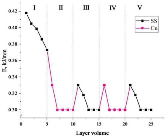
Figure 3.
Dependence of heat input values on the layer number in the manufacturing of bimetallic layered macrocomposite. Black dots show values for steel; red dots show values for copper.
For convenience, the bimetallic layered macrocomposite was divided into five areas: area I—printing the first five layers of stainless steel onto the substrate; II and IV—printing five layers of copper onto the already deposited steel; III and V—printing stainless steel layers onto the already deposited copper layers.
A gradual decrease from 0.42 kJ/mm to 0.38 kJ/mm occurs during the printing process as one moves away from the cooled substrate. Due to the heat accumulation in the sample, the creation of the molten pool and the melting of the filament occur with a reduced electron beam power. After printing the first five steel layers, the heat input values of zones II–V occurred in the range of 0.33–0.30 kJ/mm. This printing mode was chosen to ensure the contact of layers of dissimilar materials. The printing parameters used were aimed at adjusting the values of thermal investment, influencing the temperature gradient and taking into account the difference of chemical and thermophysical properties of dissimilar materials.
Figure 4 shows the morphology of the layered polymetallic sample.
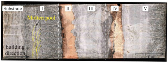
Figure 4.
Optical microscopy of the longitudinal section of a sample of bimetal layered macrocomposite. The white dashed lines show the boundaries of the sample by zone. The boundaries of the melt pool are marked with yellow lines. The sample was divided into five areas: area I—the first 5 layers of stainless steel on the substrate; II and IV—5 layers of copper on the already deposited steel; III and V—stainless steel layers on the already deposited copper layers.
Surface macrodefects formed during vertical wall growth do not affect the internal macrostructure of the sample, except for the disturbance of layer thicknesses. Due to the difference in melting temperature of the materials, a disturbance of the uniform thickness of the copper layer in the longitudinal section can be observed in Figure 4. The average value of the thickness of the copper layers is 4.1 ± 0.5 mm. Typical characteristics for additively manufactured products are observed, where overlapping molten pools with a semi-ellipse shape are formed. A middle-ground approach uses geometry of the melt pool and simulates a series of overlapping semi-circles or semi-ovals. Lack-of-fusion porosity depends on both the melt pool size as well as the scanning pattern. For a given melt pool size, the minimum depth of overlap is defined [28]. This quantity is affected by the hatch distance of the melt pool, which then dictates the maximum layer thickness. The formation of a molten pool with a semi-ellipse shape is characteristic of various methods of additive manufacturing, both for ferrous [29] and for non-ferrous metals [30], due to the peculiarities of the process. In terms of their size, melt pools are statistically 1.1–1.3 mm in width and 0.5–0.7 mm in depth. The molten pool boundaries in the sample are visible as “fish-scales” [31], filled with a cellular structure [32].
A detailed discussion of the microstructure of each zone separately (I, II, III, IV and V) of the bimetallic layered macrocomposite is given below.
3.2. Microstructure of Copper Interlayers of Zones II and IV
Copper interlayers of the sample are of particular scientific interest due to the effect of grain size, which is described by the Hall–Petch ratio. In this case (Figure 5), a fine-grained structure is observed in the copper interlayers (zone II and IV).
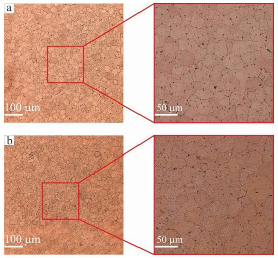
Figure 5.
Optical microscopy of copper interlayers: (a) zone II; (b) zone IV. Copper interlayers have only equiaxed grains with an average size of 28.5 ± 0.2 μm.
In a previous study, when C11000 copper was deposited on an AISI 321 steel substrate, a region with a fine-grained structure, of not more than 1 mm in length, was observed by Osipovich et al. [33]. Since the growth process of the sample in zones II and IV was continuous, a homogeneous growth of coarse grains over the entire wall height would be expected. However, microstructural analysis reveals only equiaxed grains with an average size of 28.5 ± 0.2 μm.
When C11000 copper layers are deposited onto already consolidated 321 stainless steel layers, some grains grow, due to the adjacent ones, by migration of high-angular boundaries, i.e., collective recrystallization takes place. In this case, grain boundaries migrate, and an equiaxial structure with minimal surface energy and grains of equal size and shape is formed. One of the factors contributing to the formation of an equiaxed fine-grained copper structure can be the alloying of copper by iron, as well as elements present in the composition of austenitic steel. Particles of more refractory metals will contribute to the formation of a large number of crystallization nuclei during solidification of the product. At the same time, impurity atoms and second phase inclusions (in the transition zone) are the factors that prevent the migration of grain boundaries. As the driving force of collective recrystallization decreases as it develops, the grain growth stops when it reaches a certain value. However, first of all, the difference between directional solidification (constrained growth) results in the formation of oriented cells or oriented dendrites and free solidification (unconstrained growth), which results in equiaxed dendrite (equiaxed grain) formation [34]. The columnar structure is formed due to the so-called constrained solidification whereas the equiaxed grains appear when the unconstrained solidification takes place. Since only five layers of copper have been deposited, the influence of these factors is not reduced and there is no directed grain growth of the elongated shape. Directed grain growth is facilitated by the slow heat dissipation and high temperature gradient generated by the additive manufacturing process [35].
3.3. Microstructure of Steel I, III and V Zones
Figure 6 shows the morphology of the grain–dendrite structure of stainless steel, zones I and III. This morphology includes both equiaxial and columnar grains described earlier [36].
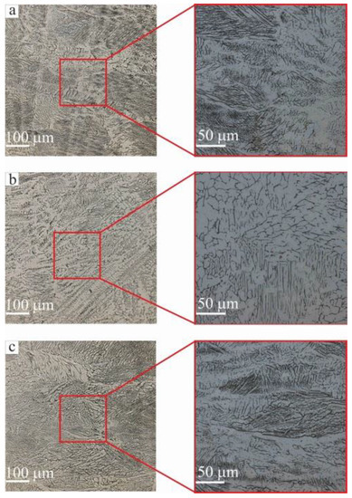
Figure 6.
Optical microscopy of steel areas: (a) zone I; (b) zone III; (c) zone V. The morphology of the grain–dendrite structure of stainless steel areas.
A common feature of additive steel macroimages is the fine-grained microstructure, typical for AM [32]. Elongated and oriented grains depending on manufacturing process parameters have been discussed previously [37]. It has been noted that the evolution of crystallization cells is related to the segregation of alloying elements at the interfaces, leading to microsegregation. It should be noted that solute microsegregation transforms into solute redistribution after back-diffusion into the solid [38]. Equiaxial cells can be either small or large with sizes of 0.2–0.6 μm and 1–2 μm, respectively. In this case, ferrite is located between the primary arms of this cell structure (dendrites) [39]. Heating ferrite to 912 °C leads to the formation of tiny austenite grains at the boundaries of the ferrite grains. Further heating leads to the growth of these new austenitic grains with complete replacement of the ferrite grains by austenitic grains—iron transformations occur. Since the electron beam process of additive manufacturing is a layer-by-layer deposition of material during sample manufacturing, there is a constant re-melting of the already deposited layers, i.e., thermal cycling. It seems that solidification which appears after re-melting is, in reality, rapid solidification. In the case of the rapid solidification, the phenomenon of microsegregation (as well as redistribution) is slightly modified by an increase in the partition ratio, k, as explained previously [40]. However, the proper behavior of the partition ratio during rapid solidification has been defined [41]. Thermal cycling leads to an evolution of the structure by height in individual zones—I, III and V—from small to large dendrites. Optical microscopy showed that the structures of stainless steel in zones I and V are similar (Figure 6a,c). This means an increase in dendrite grain size. The explanation for this is the thermal energy provided by the powerful electron beam, which to some extent can reduce the rate of the solidification process, thereby giving the dendrite more time to become coarse-grained during the solidification process. The dendritic structure mainly developed with a deviation from the building direction (z) due to a change in the temperature gradient during solidification.
The microstructures for EBAM-manufactured steel 321 in different parts of zone I, III and V are shown in Figure 7.
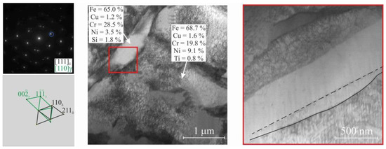
Figure 7.
SAED pattern with interpretation and dark-field TEM image for steel areas. The elemental compositions of the γ- and δ-Fe regions in wt. % revealed by EDS analysis. The typical composition of the ferrite phase is Fe-(27.2–29.3)Cr-(3.2–3.8)Ni (wt. %). The red rectangle marks the enlarged zone of δ-ferrite lamellae, the boundaries of which are partially curved.
TEM images clearly show that the steel microstructure contains two phases—Austenite and acicular δ-ferrite. The morphology of δ-ferrite dendrites does not depend on the position in the steel blank (Figure 7). According to the EDS analysis, δ-ferrite lamellae are enriched in chromium and depleted in nickel. The typical composition of the ferrite phase is Fe-(27.2–29.3)Cr-(3.2–3.8)Ni (wt. %). The elemental composition of the austenitic phase is proportional to the initial wire composition, but the chromium and nickel content is somewhat excessive—Fe-(18.3–19.1)Cr-(9.4–10.3)Ni (wt. %). δ-ferrite in the form of lamellae 300–500 nm wide is uniformly distributed in the steel structure. The boundaries between phases are partially curved (Figure 7) and partially faceted by the Kurdjumov–Sachs orientation relationship between austenite and ferrite. However, δ-ferrite is a high-temperature phase and cannot be observed as it undergoes phase transformations at room temperature. However, based on the literature analysis [42], the above features indicate that δ-ferrite formed at high temperature was fixed by quenching, and it became possible to see it at room temperature.
Thus, the morphology of zones I, III and V is characterized by a grain–dendrite structure, with the growth of elongated dendrites, with ferrite located between the primary dendrite arm spacing, associated with thermal cycling, and the direction of dendrite growth inherited by the direction of the fabrication process.
To better understand the formation of δ-Fe and its different volume fraction in zones I, III and V of the sample, quantitative studies were carried out using several methods: X-ray, metallographic and local-type ferritometer measurements (Figure 8 and Figure 9). The relative intensities of the γ-Fe and δ-Fe phases were calculated using Formula (2) [43]:
where Iδ is the integral intensity of the peaks corresponding to the δ-Fe phase; ∑IA is the sum of all analyzed integral intensities.
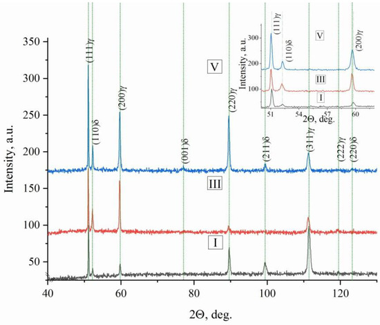
Figure 8.
X-ray diffraction of steel areas of bimetallic layered macrocomposite in zones I, III and V. The enlarged image shows X-ray peaks in a section of angles from 52 to 62.
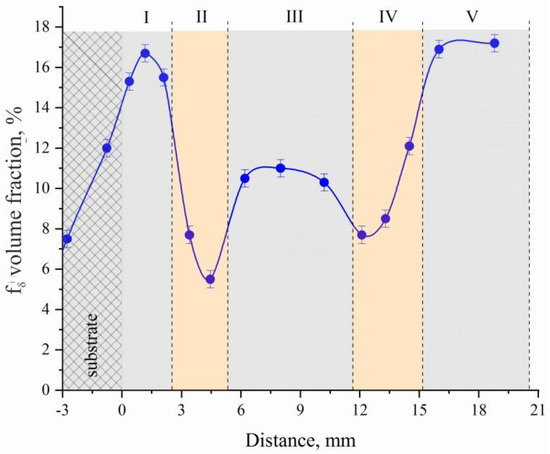
Figure 9.
Dependence of δ-Fe volume fraction on distance of substrate using a local type ferritometer.
Moreover, the volume fraction of δ-Fe in different parts of the sample is different: for zones I and V of steel sections, the volume fraction of δ-Fe varies within the range fI,V(δ-Fe) = (16.3–17.2); for zone III, a decrease in fII(δ-Fe) of 1.7–1.9 times as compared to the volume fraction for zones I and V of steel sections is typical.
It is seen that all experimental methods of determining the volume fraction of the δ-Fe phase are consistent with each other. There is a general tendency for the volume fraction to decrease in the middle of the sample and when approaching the copper interlayers, zones II and IV. This is due to the fact that copper, like nickel, is a stabilizer of γ-Fe, in this case, the ferrite that occurs during the last stages of solidification [44]. The liquid projection begins in the peritectic region in the Fe–Ni system and proceeds to the eutectic reaction in the Cr–Ni system in the Fe–Cr–Ni ternary system. The eutectic ferrite is then located along the boundaries of the austenite grains, in contrast to Widmanstatten pattern morphologies, in which the ferrite is contained mainly in the core grains. The microstructure, as shown in Figure 6, in this alloy, can be characterized by regions of both eutectic ferrite and skeletal ferrite. The characteristics of Widmanstatten pattern morphologies of alloy 321 were also revealed. Values for the alloying elements to calculate the Ni–Cr equivalents ratio were obtained by SEM. Figure 10 shows the variation in the basic and alloying elements of the material.
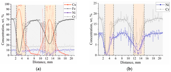
Figure 10.
Changes in the elemental composition (SEM EDS analysis) with the distance from the substrate in bimetal laminate macrocomposite (a) produced by electron beam additive manufacturing and changes elements necessary for the analysis of equivalents (b).
The element composition in the 2 to 4 mm and 10 to 14 mm areas corresponds to the chemistry of C11000 copper. In the remaining height areas, the chemical composition corresponds to the composition of stainless steel 321. In the graph of the dependence of elemental composition on the distance to the zones of material supply change from stainless steel to copper and vice versa, there is an area in which the composition of austenitic steel is different from that shown in Table 1 and there is a fairly high concentration of copper. Analysis of the data allows us to conclude that in the transition zone, the austenitic steel is alloyed with copper and there is the formation of a two-phase region—copper and austenitic stainless steel alloyed with copper. This does not contradict the available data on the Fe–Cu phase diagram [45], according to which intermetallic compounds based on iron and copper are not formed, but a limited amount of copper (≈5.8% at 1083 °C) can dissolve in γ-Fe. As the number of spherical inclusions of copper decreases with distance from the interface, the concentration of copper also becomes lower. The presence of a small concentration of iron in the copper part of the bimetal sample near the interface may be due to the formation of a solid solution of iron in copper, although the solubility of iron in copper is rather low (≈2.8% at 1083 °C). Creq/Nieq ratios [46] were used for the theoretical calculation, using formulas for equivalents ((3) and (4)):
Creq = Cr + 1.37 × Mo + 1.5 × Si +2 × Nb + 3 × Ti
Nieq = Ni + 0.31 × Mn + 22 × C + 14.2 × N + Cu
The graph of the equivalent dependence is shown in Figure 11.
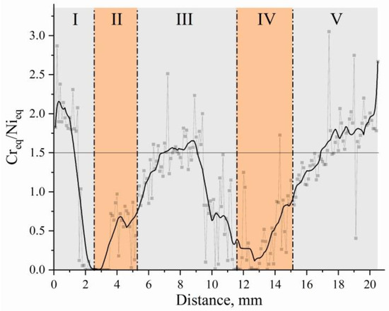
Figure 11.
Change in the equivalent Creq and Nieq ratio to the distance from the substrate in bimetal laminate macrocomposite produced by electron beam additive manufacturing.
The results of studies [47] showed that if the content of Cr and Ni in stainless steel is the same and the Creq/Nieq value is less than 1.5, then the solidification mainly starts from the γ-phase. It is seen that the value of the equivalent Creq and Nieq ratio in zone III is essentially lower, which agrees with the results of the measurement of the δ-Fe volume fraction presented above. In other words, the studied zone III is provided by the process conditions under which δ-Fe at the crystallization stage is formed to a lesser extent than in zones I and V. Just as with further cooling, the least amount of residual δ-Fe will remain in this zone.
3.4. Microstructure of “SS–Cu” and “Cu–SS” Boundaries
During the copper filament deposition step, a sharp boundary between Cu and Fe is formed on the already deposited steel layers (Figure 12a). It could be compared to the formation of the oriented cells within the diffusion joint (interconnection) formation, as has been described [48].
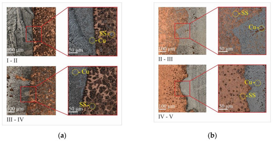
Figure 12.
Optical microscopy of boundary of “SS–Cu” (a) and “Cu–SS” (b) in bimetal laminate macrocomposite produced by electron beam additive manufacturing.
Interfacial interaction occurs in both the copper and iron parts. Cu particles, with an average size of 5 µm, are formed directly near the sharp boundary with the iron matrix. Fe particles with an average size of 10 µm are formed in the copper matrix. Since the interfacial interaction occurs at the Fe and Cu boundary at equal values of the component concentrations, structural elements such as solid solutions of copper in iron and of iron in copper with an additional mutual dissolution of the alloying elements and mechanical mixtures of the system components are formed in this region. The mechanical mixture near the boundary region is formed by re-melting the already applied stainless steel layer when the copper layer is applied. An electron beam forms a melt pool in which, under the influence of the temperature gradient, with different density values of copper and steel, their distinctive feature as a non-mixing system, emerges a narrow region up to 200 µm with formed inclusions of these materials.
The lack of thermal stability, which was discussed above, is associated with sharp thermal gradients due to the different thermal conductivity of materials. This leads to the appearance of a curved interface between the first steel layer and the copper layers already deposited (Figure 12b). During the deposition of the top layer, it is confined to the much cooler bottom layer, causing elastic compressive deformation. However, at elevated temperatures, the yield strength of the top layer decreases, allowing for plastic compressive deformation. Cooling of the plastically compressed top layer causes it to shrink, causing a bending angle with respect to the direction of the layer deposition. This results in a tensile stress in the direction of growth. It is important to note that this mechanism occurs in the solid phase [44].
Based on microstructural studies, we can conclude that zones II and IV are FCC copper; zones I, II and V are γ + δ-Fe with different δ-ferrite contents (Figure 13) in the boundary zones from copper to steel and steel to copper (Figure 14a). The different structure is due to the fact that copper hardens iron (Figure 14b).
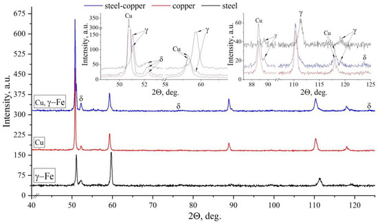
Figure 13.
X-ray diffraction of bimetal laminate macrocomposite in zones I, III and IV–V boundary of “SS–Cu”.
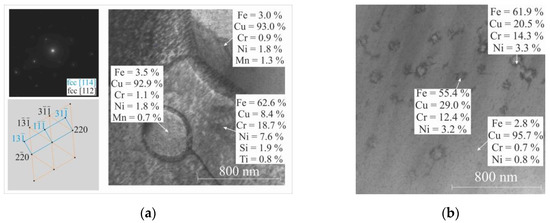
Figure 14.
TEM image of bimetal laminate macrocomposite boundary: (a) “SS–Cu” shows hardening of steel with copper; (b) “Cu–SS” shows spinodal decomposition. The elemental compositions of the Cu-based and Fe-based samples in wt. % as revealed by TEM EDS analysis.
One of the most important types of solid solution decays is spinodal decomposition [44]. Spinodal decomposition occurs most often during rapid cooling or quenching with tempering.
Many phenomena are associated with the decomposition of solid solutions. The kinetics of decomposition can be significantly affected by the presence of defects in the crystal lattice and the elastic stress fields associated with them. Elastic fields can change significantly during decomposition, which may cause such phenomena as cold brittleness, temper embrittlement of steels, embrittlement of nanocrystalline materials during electrolytic vaporization and other types of ductile–brittle transitions occurring in the grain boundary region. A study of the microstructure morphology in the Cu–Fe transition region revealed one of two characteristic patterns: disc-shaped precipitations formed randomly and arranged over the matrix. The existence of this disintegration pattern leads to the conclusion that the nucleation and growth mechanism corresponds to disc-shaped precipitations arranged randomly [44]. It is possible that chaotically distributed disc-shaped precipitations can further lead to the formation of a modulated structure. In most experiments, spinodal decomposition is obtained after rapid quenching of the alloys and subsequent annealing at lower temperatures. This heat treatment sequence can include sequential layer deposition in wire-feed electron beam additive manufacturing. Rapid heat dissipation occurs due to the previously deposited copper layers, which, in this case, act as a substrate on which successive layers of stainless steel wire are successively deposited.
3.5. Mechanical Testing
The identified features of the microstructure affect the characteristics of the mechanical properties. Microhardness measurements were carried out along the height of a bimetallic sample (Figure 15) in the work.
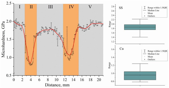
Figure 15.
Dependence of the microhardness values on distance from substrate of the bimetallic layered macrocomposite sample. Block diagrams of microhardness measurements in the steel–copper boundary zone without jumps in values beyond the error limits.
The change in microhardness along the height of the multilayered sample is similar to the change in chemical composition along the height (Figure 10a). The analysis of the distribution of microhardness at transitions through copper layers testifies to a sharp change in mechanical properties in a material from a value of microhardness of 1.85 GPa, corresponding to austenite steel, to a value of 0.91 GPa in the copper part of a sample. The gradual change in microhardness on the boundary of Fe–Cu zones is connected with partial inclusion of copper in steel, and on the boundary of Cu–Fe zones—inclusions of steel in copper layers. Basically, such changes are connected with the formation of mechanical mixtures of components of the system at various structural-scale levels and are not caused by the formation of new phases.
The measurement result of the coefficient of thermal linear expansion (CTE) is shown in Figure 16. The CTE values for copper, steel and polymetallic samples are αT(Cu) = 1.83992 × 10⁻⁵, αT(SS) = 1.80035 × 10⁻⁵ and αT(SS-Cu) = 1.74819 × 10⁻⁵, respectively. The additively grown copper and steel samples were found to have a higher CTE compared to the polymetallic sample.
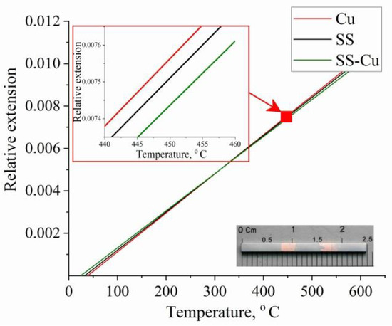
Figure 16.
Measurement result of the thermal linear expansion coefficient. Typical result for stainless steel (black curves) and copper (red curves). Solid curves are the result for the bimetallic layered macrocomposite sample.
As can be seen from Figure 12, the Fe–Cu and Cu–Fe transition boundaries have a complex shape. At the same time, as written above, the alloying of copper with steel and the mixing of copper into the steel layers takes place. If we take into account the total length of the transition boundaries up to 1 mm, the CTE value is just in the range of αT(Cu) > αT(SS-Cu) > αT(SS). With the difference in CTE values, the components of the polymetallic product create stresses at the component boundaries when heated and thereby prevent the expansion of the polymetallic sample. As a result, the polymetallic zone boundaries are stressed and mutually limit component expansion when heated. This can have a positive effect in the fabrication of structural parts operated in a large temperature range, when it is necessary to consider gaps in the mating of parts.
The stress–strain plots are shown as the extreme values of the mechanical characteristics in Figure 17. The green shaded area highlights the values that include all of the obtained values of ultimate strength, yield strength and strain to failure. As can be seen, the test result of sample #1, cut in the extreme position of the polymetallic sample, has the worst performance. This is due to a defect in the form of a discontinuity, which caused the sample to fracture. The remaining tensile samples #2–9 have similar characteristics and have tensile strength σUS = 314 ± 23 MPa, yield strength σYS = 194 ± 15 MPa and strain to failure ε = 0.16 ± 0.01 (Figure 17b).
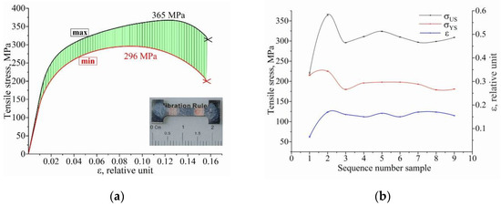
Figure 17.
Results of uniaxial tension of bimetallic samples: (a) dependence of σ(ε) with minimum (red curve) and maximum (black curve) tensile strength; (b) experimental yield strength YS, ultimate strength US and deformation ε values of the samples.
Figure 18 shows fractography of the sample after fracture.
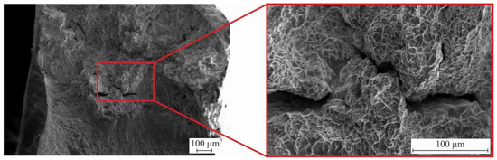
Figure 18.
Fractographic images after uniaxial tension of bimetallic layered macrocomposite.
Fracture analysis showed that intergrain fracture occurs. At the same time, the surface of the fracture does not have chipping areas, but there are facets of individual grains and small “cups”. The above signs indicate that ductile–brittle fracture occurred in the samples.
4. Conclusions
1. A bimetallic layered macrocomposite was successfully fabricated by electron beam additive manufacturing with alternating filament feeding of stainless steel and copper.
2. Macrostructural analysis of the macrocomposite showed complete deposition of the layers and the absence of pore- and crack-type defects.
3. Microstructural studies of stainless steel layers of zones I, III and V by X-ray phase analysis and transmission electron microscopy determined the presence of two phases—austenite γ-Fe and coarse acicular δ-Fe in the form of lamellae with a width of 300–500 nm.
4. The effect of copper stabilization of γ-Fe in stainless steel layers of zone III between copper interlayers was revealed, manifesting itself in a reduction of 1.7–1.9 times of the δ-Fe volume fraction as compared to stainless steel layers of zones I and V, not bounded by copper interlayers on both sides. For I and V zones of steel sections, according to close microstructure, the value of the δ-Fe volume fraction varies in the range of fI,V (δ-Fe) = 16.3–17.2%.
5. In the copper layers of zones II and IV, collective recrystallization with formation of equiaxed grains of size 28.5 ± 0.2 μm takes place.
6. Different mechanisms of boundary formation during 3D printing of stainless steel and copper are established: during formation of the SS–Cu boundary, austenite hardening by copper takes place; during formation of the Cu–SS boundary, spinodal decomposition is observed.
7. Interfacial interaction occurs in the boundary regions, which is observed in both copper and iron: Cu particles with an average size of 5 µm are formed immediately near the sharp boundary of the boundary zone in the region of the iron matrix, while Fe particles with an average size of 10 µm are formed in the copper matrix.
8. The values of mechanical properties of the layered bimetal lie in the range of values of mechanical properties of monometallic products based on Fe and Cu, manufactured by wire-feed electron beam additive manufacturing. The strength of the sample is lower than that of pure additive steel and higher than that of pure additive copper.
Author Contributions
Conceptualization, Funding Acquisition, Investigation, Writing—Original Draft, K.O.; Methodology, Investigation, Data Curation, Visualization, A.V.; Methodology, Resources, Investigation, A.C.; Investigation, Data Curation, Formal analysis, D.G.; Methodology, Resources, N.S. (Nikolai Shamarin); Investigation, Data Curation, Formal analysis, N.S. (Nikolai Savchenko); Conceptualization, Writing—Review and Editing, E.K. All authors have read and agreed to the published version of the manuscript.
Funding
The work was performed according to the government research assignment for ISPMS SB RAS, project FWRW-2019-0034.
Institutional Review Board Statement
Not applicable.
Informed Consent Statement
Not applicable.
Data Availability Statement
Results data can be obtained upon request to the corresponding author.
Conflicts of Interest
The authors declare no conflict of interest.
References
- Kumar, N.; Yuan, W.; Mishra, R.S. Friction Stir Welding of Dissimilar Alloys. In Friction Stir Welding of Dissimilar Alloys and Materials; Elsevier: Amsterdam, The Netherlands, 2015; pp. 43–69. [Google Scholar]
- Martinsen, K.; Hu, S.J.; Carlson, B.E. Joining of Dissimilar Materials. CIRP Ann. Manuf. Technol. 2015, 64, 679–699. [Google Scholar] [CrossRef]
- Gladkovsky, S.V.; Kuteneva, S.V.; Sergeev, S.N. Microstructure and Mechanical Properties of Sandwich Copper/Steel Composites Produced by Explosive Welding. Mater. Charact. 2019, 154, 294–303. [Google Scholar] [CrossRef]
- Gao, H.T.; Liu, X.H.; Qi, J.L.; Ai, Z.R.; Liu, L.Z. Microstructure and Mechanical Properties of Cu/Al/Cu Clad Strip Processed by the Powder-in-Tube Method. J. Mater. Process. Technol. 2018, 251, 1–11. [Google Scholar] [CrossRef]
- Wang, F.; Luo, G.N.; Huang, J.; Liu, Y. Properties Improvement of Atmospheric Plasma Sprayed Tungsten Coating by Annealing. Surf. Coat. Technol. 2019, 358, 276–281. [Google Scholar] [CrossRef]
- Chen, X.; Sun, W.; Li, X.; Wang, X.; Yan, H.; Li, K. Experimental and Numerical Studies on W–Cu Functionally Graded Materials Produced by Explosive Compaction–Welding Sintering. Fusion Eng. Des. 2018, 137, 349–357. [Google Scholar] [CrossRef]
- Sarkar, S.; Srivastava, C.; Chattopadhyay, K. Development of A New Class of High Strength Copper Alloy Using Immiscibility Route in Cu-Fe-Si System: Evolution of Hierarchical Multi-Scale Microstructure. Mater. Sci. Eng. A 2018, 723, 38–47. [Google Scholar] [CrossRef]
- Vysotskiy, I.V.; Malopheyev, S.S.; Mironov, S.Y.; Kaibyshev, R.O. Optimization of Friction-Stir Welding of 6061-T6 Aluminum Alloy. Phys. Mesomech. 2020, 23, 402–429. [Google Scholar] [CrossRef]
- Lusch, C.; Börsch, M.; Heidt, C.; Magginetti, N.; Sas, J.; Weiss, K.P.; Grohmann, S. Qualification of Electron-Beam Welded Joints between Copper and Stainless Steel for Cryogenic Application. In IOP Conference Series: Materials Science and Engineering; Institute of Physics Publishing: London, UK, 2015; Volume 102, p. 012017. [Google Scholar]
- Mai, T.A.; Spowage, A.C. Characterisation of Dissimilar Joints in Laser Welding of Steel-Kovar, Copper-Steel and Copper-Aluminium. Mater. Sci. Eng. A 2004, 374, 224–233. [Google Scholar] [CrossRef]
- Chen, X.; Wang, X.; Liu, Z.; Hu, Z.; Huan, P.; Yan, Q.; Hiromi, N. Effect of Cu content on microstructure transformation and mechanical properties of Fe-Al dissimilar laser welded joints. Opt. Laser Technol. 2020, 126, 106078. [Google Scholar] [CrossRef]
- Tan, C.; Zhou, K.; Ma, W.; Min, L. Interfacial Characteristic and Mechanical Performance of Maraging Steel-Copper Functional Bimetal Produced by Selective Laser Melting Based Hybrid Manufacture. Mater. Des. 2018, 155, 77–85. [Google Scholar] [CrossRef]
- Le, T.N.; Lo, Y.L. Effects of Sulfur Concentration and MARANGONI Convection on Melt-Pool Formation in Transition Mode of Selective Laser Melting Process. Mater. Des. 2019, 179, 107866. [Google Scholar] [CrossRef]
- Christ, J.F.; Aliheidari, N.; Ameli, A.; Pötschke, P. 3D Printed Highly Elastic Strain Sensors of Multiwalled Carbon Nanotube/Thermoplastic Polyurethane Nanocomposites. Mater. Des. 2017, 131, 394–401. [Google Scholar] [CrossRef]
- Yilmaz, O.; Aksoy, M. Investigation of Micro-Crack Occurrence Conditions in Diffusion Bonded Cu-304 Stainless Steel Couple. J. Mater. Process. Technol. 2002, 121, 136–142. [Google Scholar] [CrossRef]
- Luo, J.; Xiang, J.; Liu, D.; Li, F.; Xue, K. Radial Friction Welding Interface between Brass and High Carbon Steel. J. Mater. Process. Technol. 2012, 212, 385–392. [Google Scholar] [CrossRef]
- Munitz, A. Metastable Liquid Phase Separation in Tungsten Inert Gas and Electron Beam Copper/Stainless-Steel Welds. J. Mater. Sci. 1995, 30, 2901–2910. [Google Scholar] [CrossRef]
- Magnabosco, I.; Ferro, P.; Bonollo, F.; Arnberg, L. An Investigation of Fusion Zone Microstructures in Electron Beam Welding of Copper-Stainless Steel. Mater. Sci. Eng. A 2006, 424, 163–173. [Google Scholar] [CrossRef]
- Chen, S.; Huang, J.; Xia, J.; Zhang, H.; Zhao, X. Microstructural Characteristics of a Stainless Steel/Copper Dissimilar Joint Made by Laser Welding. Metall. Mater. Trans. A Phys. Metall. Mater. Sci. 2013, 44, 3690–3696. [Google Scholar] [CrossRef]
- Durgutlu, A.; Okuyucu, H.; Gulenc, B. Investigation of Effect of the Stand-Off Distance on Interface Characteristics of Explosively Welded Copper and Stainless Steel. Mater. Des. 2008, 29, 1480–1484. [Google Scholar] [CrossRef]
- Mironov, S.; Sato, Y.S.; Kokawa, H. Grain Structure Evolution during Friction-Stir Welding. Phys. Mesomech. 2020, 23, 21–31. [Google Scholar] [CrossRef]
- Han, L.; Liu, J.; Tang, H.; Ma, X.; Zhao, W. Investigation on the Properties of Nanostructured Cu Alloy Prepared by Mechanical Milling and Reactive Hot-Pressing. J. Alloy. Compd. 2018, 742, 284–289. [Google Scholar] [CrossRef]
- Weigl, M.; Schmidt, M. Influence of the Feed Rate and the Lateral Beam Displacement on the Joining Quality of Laser-Welded Copper-Stainless Steel Connections. Phys. Procedia 2010, 5, 53–59. [Google Scholar] [CrossRef]
- Imran, M.K.; Masood, S.H.; Brandt, M. Direct Metal Deposition of H13 Tool Steel on Copper Alloy Substrate: Parametric Investigation. Lasers Manuf. Mater. Process. 2015, 2, 242–260. [Google Scholar] [CrossRef]
- Shu, X.; Chen, G.; Liu, J.; Zhang, B.; Feng, J. Microstructure Evolution of Copper/Steel Gradient Deposition Prepared Using Electron Beam Freeform Fabrication. Mater. Lett. 2018, 213, 374–377. [Google Scholar] [CrossRef]
- Osipovich, K.S.; Astafurova, E.G.; Chumaevskii, A.V.; Kalashnikov, K.N.; Astafurov, S.V.; Maier, G.G.; Melnikov, E.V.; Moskvina, V.A.; Panchenko, M.Y.; Tarasov, S.Y.; et al. Gradient Transition Zone Structure in “Steel–Copper” Sample Produced by Double Wire-Feed Electron Beam Additive Manufacturing. J. Mater. Sci. 2020, 55, 9258–9272. [Google Scholar] [CrossRef]
- Tarasov, S.Y.; Filippov, A.V.; Savchenko, N.L.; Fortuna, S.V.; Rubtsov, V.E.; Kolubaev, E.A.; Psakhie, S.G. Effect of Heat Input on Phase Content, Crystalline Lattice Parameter, and Residual Strain in Wire-Feed Electron Beam Additive Manufactured 304 Stainless Steel. Int. J. Adv. Manuf. Technol. 2018, 99, 2353–2363. [Google Scholar] [CrossRef]
- Oliveiraa, J.P.; LaLonde, A.D.; Ma, J. Processing Parameters in Laser Powder Bed Fusion Metal Additive Manufacturing. Mater. Des. 2020, 193, 108762. [Google Scholar] [CrossRef]
- Pinkerton, A.J.; Li, L. Direct Additive Laser Manufacturing Using Gas and Water-Atomised H13 Tool Steel Powders. Int. J. Adv. Manuf. Technol. 2005, 25, 471–479. [Google Scholar] [CrossRef]
- Hebert, R.J. Viewpoint: Metallurgical Aspects of Powder Bed Metal Additive Manufacturing. J. Mater. Sci. 2016, 51, 1165–1175. [Google Scholar] [CrossRef]
- Zhao, X.; Song, B.; Zhang, Y.; Zhu, X.; Wei, Q.; Shi, Y. Decarburization of Stainless Steel during Selective Laser Melting and Its Influence on Young’s Modulus, Hardness and Tensile Strength. Mater. Sci. Eng. A 2015, 647, 58–61. [Google Scholar] [CrossRef]
- Kempen, K.; Yasa, E.; Thijs, L.; Kruth, J.P.; Van Humbeeck, J. Microstructure and Mechanical Properties of Selective Laser Melted 18Ni-300 Steel. Phys. Procedia 2011, 12, 255–263. [Google Scholar] [CrossRef]
- Osipovich, K.S.; Chumaevskii, A.V.; Eliseev, A.A.; Kalashnikov, K.N.; Kolubaev, E.A.; Rubtsov, V.E.; Astafurova, E.G. Peculiarities of Structure Formation in Copper/Steel Bimetal Fabricated by Electron-Beam Additive Technology. Russ. Phys. J. 2019, 62, 1486–1494. [Google Scholar] [CrossRef]
- Wołczyński, W.; Ivanova, A.A.; Kwapisiński, P. On Consonance between a Mathematical Method for the CET Prediction and Constrained / Unconstrained Solidification. Proc. Manuf. 2019, 30, 459–466. [Google Scholar] [CrossRef]
- Utyaganova, V.; Filippov, A.; Tarasov, S.; Shamarin, N.; Gurianov, D.; Vorontsov, A.; Chumaevskii, A.; Fortuna, S.; Savchenko, N.; Rubtsov, V.; et al. Characterization of AA7075/AA5356 Gradient Transition Zone in an Electron Beam Wire-Feed Additive Manufactured Sample. Mater. Charact. 2021, 172, 110867. [Google Scholar] [CrossRef]
- Campanelli, S.L.; Contuzzi, N.; Posa, P.; Angelastro, A. Study of the Aging Treatment on Selective Laser Melted Maraging 300 steel. Mater. Res. Express 2019, 6, 066580. [Google Scholar] [CrossRef]
- Abd-Elghany, K.; Bourell, D.L. Property Evaluation of 304L Stainless Steel Fabricated by Selective Laser Melting. Rapid Prototyp. J. 2012, 18, 420–428. [Google Scholar] [CrossRef]
- Wołczyński, W. Back-Diffusion In Crystal Growth. Eutectics. Arch. Metall. Mater. 2015, 60, 2403–2407. [Google Scholar] [CrossRef]
- Fortuna, S.V.; Gurianov, D.A.; Kalashnikov, K.N.; Chumaevskii, A.V.; Mironov, Y.P.; Kolubaev, E.A. Directional Solidification of a Nickel-Based Superalloy Product Structure Fabricated on Stainless Steel Substrate by Electron Beam Additive Manufacturing. Metall. Mater. Trans. A Phys. Metall. Mater. Sci. 2021, 52, 857–870. [Google Scholar] [CrossRef]
- Senderowski, C.; Wołczyński, W.; Fikus, B.; Panas, A.J. Solidification Mechanism of the D-Gun Sprayed Fe-Al Particles. Arch. Metall. Mater. 2017, 62, 2391–2397. [Google Scholar] [CrossRef][Green Version]
- Alabiev, V.R.; Dozorov, A.V.; Savvateeva, I.A.; Druzyanova, V.P.; Sangadzhiev, M.M. Economic Practicability of the Implementation of the Mine Refrigeration Technology for Normalization of Thermal Conditions. Arch. Metall. Mater. 2020, 65, 271–284. [Google Scholar] [CrossRef]
- Astafurova, E.G.; Panchenko, M.Y.; Moskvina, V.A.; Maier, G.G.; Astafurov, S.V.; Melnikov, E.V.; Fortuna, A.S.; Reunova, K.A.; Rubtsov, V.E.; Kolubaev, E.A. Microstructure and Grain Growth Inhomogeneity in Austenitic Steel Produced by Wire-Feed Electron Beam Melting: The Effect of Post-Building Solid-Solution Treatment. J. Mater. Sci. 2020, 55, 9211–9224. [Google Scholar] [CrossRef]
- Inoue, H.; Koseki, T.; Ohkita, S.; Fuji, M. Formation Mechanism of Vermicular and Lacy Ferrite in Austenitic Stainless Steel Weld Metals. Sci. Technol. Weld. Join. 2000, 5, 385–396. [Google Scholar] [CrossRef]
- Skripov, V.P.; Skripov, A.V. Spinodal Decomposition (Phase Transitions via Unstable States). Uspekhi Fiz. Nauk 1979, 128, 193. [Google Scholar] [CrossRef]
- Prince, A. Binary and Multicomponent Copper-based Systems. Met. Sci. 1979, 13, 602. [Google Scholar] [CrossRef]
- Nie, P.; Ojo, O.A.; Li, Z. Numerical Modeling of Microstructure Evolution during Laser Additive Manufacturing of a Nickel-based Superalloy. Acta Mater. 2014, 77, 85–95. [Google Scholar] [CrossRef]
- Suutala, N.; Takalo, T.; Moisio, T. The Relationship between Solidification and Microstructure in Austenitic and Austenitic-Ferritic Stainless Steel Welds. Metall. Trans. A 1979, 10, 512–514. [Google Scholar] [CrossRef]
- Okane, T.; Cenderowski, C.; Zasada, D.; Kania, B.; Janczak-Rusch, J.; Wołczyński, W. Thermodynamic Justification for the Ni/Al/Ni Joint Formation by a Diffusion Brazing. Int. J. Thermodyn. A 2011, 14, 97–105. [Google Scholar] [CrossRef]
Publisher’s Note: MDPI stays neutral with regard to jurisdictional claims in published maps and institutional affiliations. |
© 2021 by the authors. Licensee MDPI, Basel, Switzerland. This article is an open access article distributed under the terms and conditions of the Creative Commons Attribution (CC BY) license (https://creativecommons.org/licenses/by/4.0/).