Article

The Influence of Returnable Material on Internal Homogeneity of the High-Pressure Die-Cast AlSi9Cu3(Fe) Alloy

1
Department of Technological Engineering, Faculty of Mechanical Engineering, University of Zilina, Univerzitná 8215/1, 010 26 Žilina, Slovakia
2
Rosenberg-Slovakia s.r.o., Kováčska 38, 044 25 Medzev, Slovakia
*
Author to whom correspondence should be addressed.
Metals 2021, 11(7), 1084; https://doi.org/10.3390/met11071084
Submission received: 6 June 2021 / Revised: 30 June 2021 / Accepted: 3 July 2021 / Published: 6 July 2021
(This article belongs to the Special Issue Structure and Properties of Aluminium Alloys 2023)

Abstract

:
Nowadays, high-pressure die-casting technology is an integral part of industrial production. High productivity, reduced machining requirements together with the low weight and advantageous properties of aluminium alloys form an ideal combination for the production of numerous components for various industries. The experimental part of the presented article focuses on the analysis of the change in the ratio of returnable material and commercial-purity alloy in a batch depending on the internal homogeneity of castings (microstructure, porosity and microhardness) from AlSi9Cu3(Fe) alloy. The use of returnable material in the batch is a key factor in achieving the maximum use of aluminium melt, which increases the economic efficiency of production and, last but not least, has a more favorable impact on the environment. Structural analysis showed that the increase in returnable material in the batch was visibly manifested in a change in the morphology of the eutectic Si. A negative change in the morphology of the eutectic Si particles was observed after increasing the returnable material content in the batch to 75%. The evaluation of porosity at control cuts showed the influence of the increase of returnable material in the batch, where the worst results were achieved by the alloy with 90% but also the one with 55% returnable material content in the batch.

Graphical Abstract

1. Introduction

The development of automobile production has caused a large increase in the need for castings from non-ferrous metals produced by high-pressure die casting technology. The use of high-pressure castings as components in automobiles leads to a reduction in their total weight and the associated decrease in fuel consumption, which has a significant positive impact on the environment [1,2].
With the growing trend in the production of high-pressure die castings, the demands on castings are also increasing with the maximum use of the batch material. That is why the remaining unused metal (such as gating, riser and venting systems) is used in the subsequent production. Using returnable material as an additive to aluminium melt is also associated with a negative impact on the final quality of castings produced due to the introduction of hereditary properties into the melt. A key factor in the preparation of a melt with a certain proportion of returnable material is to correctly determine its optimal amount and method of processing in order to achieve unchanged results in the product quality (compared to the production of a casting from the primary material melt). As the proportion of returnable material increases, permanent deformation occurs and the amount of porosity in the resulting structure of the castings increases. Together with the returnable material, a large amount of undesirable elements is introduced into the melting process. However, returnable material forms an inseparable part of the production process due to the reduction of input costs. By adding returnable material to the melt, the melt is contaminated with oxides and hydrogen, which are part of the surface of the returnable material. The oxide layer formed on the returnable material surface may contain up to 60% aluminium hydroxide. The most suitable batch composition is 100% of the primary new alloy, but at the same time it is the least economically suitable [3,4,5,6,7].
High-pressure die-casting (HPDC) is a cost-effective process for the production of castings in large quantities and with high dimensional accuracy [8]. It is well known that porosity is a major disadvantage of high-pressure die-castings, as it can seriously affect the mechanical properties of the castings. The main source of porosity is considered to be the entrapment of air in the liquid metal during the mold filling process [9]. Therefore, it is extremely important to monitor the mold filling process and predict air trapping in order to obtain high-quality high-pressure die-castings. The improvement of the mold filling process, and thus the casting porosity reduction, is influenced by a change in the mold gating and air venting systems [10,11,12]. When filling high-pressure molds, the most frequently observed phenomenon is turbulent flow, which occurs when the inlet velocity of the melt increases to 0.5 to 15 m/s. Under such conditions, the melt stream hits the opposite wall of the mold, on which it splits into two streams. These two streams then return, and turbulent mixing of the melt with the surrounding atmosphere occurs. In this case, it is very difficult to ensure sufficient venting of the mold. The castings then contain non-metallic particles (oxides) and bubbles (pockets of air and gases) which have been swept by the turbulent melt flow. Another important factor is the content of dissolved hydrogen in the melts. Unnecessary overheating of the melt leads to a significant increase in the gas content in the melt. The solubility of hydrogen at a given temperature depends on the partial pressure of hydrogen in the surrounding atmosphere. This dependence is expressed by Sieverts’ law, which has the form for diatomic gases as follows:
S = k P H 2
where S is the solubility of hydrogen in the melt (cm3/100 g), PH2 is the partial pressure of hydrogen in the surrounding atmosphere (kPa) and k is a constant. Increasing the hydrogen content will increase the casting porosity and the overall pore size, leading to a significant deterioration in the mechanical and surface properties of the final casting [13].
Porosity due to shrinkage and due to the formation of oxide layers and reoxidation is often observed in high-pressure castings as well. Porosity due to shrinkage of liquid metal occurs in the casting clusters and hot spots. Insufficient amount of melt input during the casting process is the main reason for shrinkage in castings [14]. The melt is also exposed to the possibility of oxide layers formation during metallurgical operations until the metal solidifies in the mold. The action of reoxidation processes reduces the oxidic purity of the metal and thus causes metallurgical faults, such as bubbles (air/gas pockets) and oxide layers. During the high-pressure die-casting process, it is most often a tertiary oxidation, which is also referred to as the metal oxidation in the casting itself at the temperature interface between liquidus and solidus [15]. Also, in the case of a low mold temperature, excess spray water is trapped inside the casting. This trapped water evaporates during the casting process to form air bubbles (pockets) [16].
For high-pressure die-casting technology, secondary (remelted) aluminium alloys are usually used in which the iron content is intentionally in the range of 0.8 to 1.1 wt.% to prevent molten metal from sticking to the mold cavity [17]. However, secondary alloys with increased iron content are not used for high ductility castings [18]. Nevertheless, the use of recycled alloys with high iron content can significantly reduce the production costs of the casting by extending the lifespan of the mold. It is important to note that the manufacture and maintenance of high-pressure machines account for more than 10% of the total cost of producing HPDC castings. The use of secondary alloys is more economically advantageous (viable), and their production is also more environmentally friendly (lower energy consumption and lower CO2 emissions) [19].
High silicon content ensures good foundry properties, while the addition of copper improves the mechanical properties and machinability of the casting. Solidification of the AlSi9Cu3 aluminium alloy in high-pressure die casting is described by Bäckerud in his work. The crystallization process begins with the nucleation of dendrite-shaped primary α-phase crystals at a temperature of 575 °C. The particles of the primary α-phase grow with further cooling, and at the point of dendritic coherence the solid phase makes up 11% of the total volume. During the concentration of dendrites and also later during the eutectic crystallization of α-Al + β-Si, which begins at a temperature of about 566 °C, the intermetallic phases are in the form of iron (Al15(FeMn)3Si2 and especially Al5FeSi). At a temperature of about 503 °C, when the solid fraction makes up 94% of the volume, copper-based Al2Cu intermetallic phases begin to form, and a complex Al6Mg8Cu2Si6 intermetallic phase is formed in the remaining percentage of the liquid phase. Solidification is completed at a temperature of 490 °C. The critical temperature at which the additional flow of melt through dendrites is limited is 562 °C. At this temperature, eutectic crystallization is already taking place, and therefore the mechanical properties are highly dependent on the eutectic structure (size and shape of the eutectic grains), which can be influenced by changing the cooling rate [20,21,22].
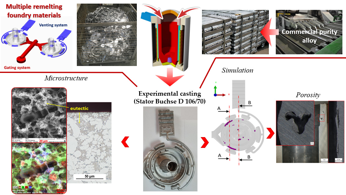
The main aim of the presented article is to describe the effect of increasing the returnable material on the internal homogeneity of a HPDC castings. The article is focused on the change of porosity and microstructure in connection with the gradual increase of the returnable material and determination of the optimal proportion of returnable material in the batch while maintaining the required quality of the castings.

2. Materials and Experimental Procedure

2.1. Alloy and Die Casting Parameters

AlSi9Cu3(Fe) is the most widely used alloy in Europe in the HPDC process and a dominant component of the castings used in the automotive industry. The experiment was performed on a Stator Buchse D 106/70 casting (Figure 1a, Rosenberg-Slovakia s.r.o, Medzev, Slovak Republic). The casting was cast in a double-cavity mold, the geometry of which is shown in Figure 1b.
The subeutectic AlSi9Cu3(Fe) alloy (A226, EN AC–46,000) was used in this work. Melting and casting of experimental alloys was performed at the company Rosenberg-Slovakia s.r.o. Melting of AlSi9Cu3(Fe) alloy and returnable material was performed using a Strikowestofen MHS 750/350 device (StrikoWestofen, Gummersbach, Germany) with a holding space capacity of 750 kg. A CLH 400 cold chamber die casting press (Polak, Mimoň, Czech Republic) with a horizontal locking mechanism with a filling chamber diameter of 80 mm and an active chamber length of 485 mm was used for casting. The maximum speed of the pressing piston during the casting process was 3 m/s and the maximum pressure in the chamber was set at 95 MPa. The temperature of the metal during casting was 710 ± 10 °C. The temperature of the mold after treatment of the stationary part was 160 ± 10 °C, and the temperature of the moveable part was 180 ± 10 °C. The melt was rotary degassed with nitrogen for 120 s before being poured into the dosing device. The degassing process took place automatically and after its completion, oxide layers were mechanically removed from the surface. Chemical compositions of AlSi9Cu3(Fe) alloy (commercial purity) and experimental alloys are given in Table 1. Chemical composition was determined by arc spark spectroscopy (Bunker–Q2 ION, manufacturer, Kalkar, Germany).
For experimental purposes, four types of AlSi9Cu3(Fe) alloy material were cast with different ratios of returnable material in combination with the primary AlSi9Cu3(Fe) alloy (commercial purity) in the batch. The amount of returnable material in the batch was gradually increased to 10%, 55%, 75%, and 90%. The alloys were designated Z10, Z55, Z75 and Z90, where the number indicates the percentage of remelted returnable material in the batch. The returnable material consisted of noncompliant castings, gating systems, and parts of venting systems (Figure 1c).

2.2. Microstructure Analysis and Microhardness

Specimens for microstructure analysis were taken from the site shown in Figure 2a (specimen thickness = 5 mm) and were prepared by coarse and fine wet grinding, polishing on an automatic machine using a diamond emulsion, and final etching. A Dix-Keller etchant with 100 mL distilled water was used for specimens evaluated by optical microscopy, and an etchant consisting of 36 mL HCl + 100 mL H2O was used for deep etchings. The images capture sites from the region near the surface (surface region) and the central region of the specimen (Figure 2b). The microstructure of alloy castings was evaluated using an NEOPHOT 32 optical microscope (OM). Deep etching (evaluation of three-dimensional morphology of eutectic silicon and intermetallic phases) was performed on a VEGA LMU II (Tescan, Brno, Czech Republic) scanning electron microscope (SEM–scanning electron microscope). The microscope was connected to energy dispersive X-ray spectroscopy (Bruker Quantax EDX analyzer, Bruker, Kalkar, Germany).
The microhardness evaluation of the primary α-phase was performed on a Hanemann type Mod 32 device at a load of 10 p. The resulting value represents the mean value from 20 measurements.

2.3. Heat Treatment

The applied heat treatment consisted of heating to 370 ± 5 °C for 3 h, followed by cooling in ambient air to 20 °C. Heat treatment was performed using a LAC electric chamber resistance furnace. The heat treatment mode was chosen based on the requirements of the Rosenberg-Slovakia s.r.o. company. Heat treatment is applied to reduce internal stresses in the casting.

2.4. Macroporosity Evaluation

The evaluation of porosity was divided into evaluation in terms of area and shape. Two cuts (incisions) were made on each casting and photographed with an AZ100 Multizoom Diascopic Microscope (Nikon, Minato, Japan). The captured images were processed by the Quick PHOTO INDUSTRIAL (version 3.1, Promica, Prague, Czech Republic) program for the surface and shape evaluation of porosity in the casting. In addition to the indicator of the percentage volume of bubbles (air/gas pockets), their geometric shape is decisive in terms of initiating tears formation at the edge of the pore. If the pores are formed in circular shapes, they are likely to have a less negative effect on the mechanical properties than the acicular or planar plate-shaped pores. A shape factor (SF) is often used to evaluate cavities in the structure of a casting:
SF = (4·π·Ap)/U2
To determine the quantitative geometric parameters of the structure, its reciprocal values of the roundness factor (s) are used:
s = U2/(4·π·Ap) = 1
where Ap is the pore area [mm2], U is the circumference of the pore cavity on the metallographic cut (incision) [mm]. The value of the roundness factor is equal to one for a circle-shaped pore. The value increases with increasing complexity and articulation (Figure 3). The factor sensitively respects the changing geometry of internal cavities, which affects the mechanical properties. Pores with a roundness factor s > 1 manifest a higher degree of disruption of the metal matrix at the same porosity than circular pores s = 1. As the factor increases, the notch effect of the pore increases and the formation of tears in the structure increases, which has a negative effect on the strength of the material.

3. Results

3.1. Microstructure–Cast State

The microstructure of the Z10 alloy (10% returnable material) cast using HPDC technology is shown in Figure 4. In the Z10 alloy with the lowest proportion of returnable material, only a small difference in the silicon particle size is visible in the optical microscope images when comparing the surface and central regions. In both cases, these are small particles of eutectics found evenly distributed in the primary α-phase.
The SEM images (red box) further identify the difference in eutectic silicon morphology based on the region. Eutectic Si crystallized in the central region in a coarse plate-like morphology typical of unmodified Al-Si alloys (Figure 4a), while eutectic silicon grains crystallized in the surface region as fine, sharp-edged and fibrous particles (Figure 4b). The change in Si morphology is due to the higher cooling rates [23,24]. It has been observed that a rapid solidification process changes the shape of the eutectic Si so that it is similar to the chemically modified eutectic Si [25]. Intermetallic phases rich in Cu and Fe are also observed in the interdendritic region and along the α-phase grain boundaries.
The microstructure of the alloy with 55% returnable material in the batch (Z55) is almost identical to that of the Z10 alloy based on the evaluation of optical microscope images (Figure 5). Fine eutectic Si particles are distributed in the primary α-phase. There was no significant change due to the increase in the returnable material content even with a closer look at the morphology of eutectic Si by means of SEM images (red box). The central region is characterized by a plate-like morphology (Figure 5a) and the surface region is characterized by finer sharp-edged Si particles (Figure 5b).
As the amount of returnable material in the batch increases, the shape of Si in the Z75 alloy changes preferentially in the central region of the specimen (Figure 6b). A slight coarsening of the eutectic Si particles can be observed in the plane of the facet of the central region. Images of deep etchings show eutectic Si in a coarse irregular morphology compared to the plate-like morphology of the Z10 and Z55 alloys. Fine coarsening can also be observed in images of deep etchings from the surface region, where, however, eutectic Si has retained the shape of finer sharp-edged particles (Figure 6a).
The highest amount of returnable material (90%) in the Z90 alloy batch led to the crystallization of coarsely irregular parts of eutectic Si with an undirected distribution in the central region of the specimen (Figure 7b). As in the case of the Z75 alloy, the surface part of the specimen is characterized by finer, and in some places thicker, sharp-edged particles of eutectic Si (Figure 7a). Due to the increase in the amount of returnable material to 75% and 90%, there was also a decrease in phases rich in Cu.

3.2. Microstructure–Heat Treatment

SEM images (central regions of the Z10 and Z55 alloy specimens) show that spheroidization occurred as a result of heat treatment (Figure 8b,d). Branching and splitting of the original hexagonal plate-like morphology (typical for the state without heat treatment) with subsequent growth of the edges and their gradual arching and thinning. The process of partial spheroidization is also observed in the specimen surface region, where rounding of fine particles of eutectic Si can be observed (Figure 8a,c).
The same effect of heat treatment is observed in specimens from the Z75 and Z90 alloys. In the central region, branching, splitting and rounding of the original plate-like morphology with an undirected distribution (Figure 9b,d), and rounding of eutectic Si particles on the edges of the specimen are observed.

3.3. Microhardness

As expected, microhardness evaluation of the primary α-phase confirmed that the primary α-phase in the region close to the surface manifested higher values than in the central region of the specimen (Figure 10).
The course of the resulting values of microhardness had an increasing trend in the cast state with an increasing content of returnable material in the batch. On the other hand, it should be added that the increase in values (in the region near the surface and in the central region as well) was in a narrow interval. After the application of heat treatment an increase in both values was observed in the Z10 alloy (by 10 HM), but in the Z55, Z75 and Z90 alloys a decrease occurred in comparison with the cast state.

3.4. Porosity

A change in porosity can be very negatively affected because, as stated in Section 2, the remelted returnable material consisted of so-called overflows and chill vents in addition to noncompliant castings and gating systems. Overflows and chill vents are important elements in solving mold venting, which can have a major impact on the quality of the final casting. When filling the mold cavity, air in the cavity is mixed with the injected metal. The air absorbed in the metal then leads to faults. Therefore, it is necessary to minimize the amount of air in the mold cavity and ensure the best possible venting of the mold [26]. The above-mentions components of the venting system are characterized by an increased content of air, oxide layers and inclusions, which are present in the aluminium melt during the subsequent remelting.
Two control cuts (incisions) were made on each casting, on which the areal porosity and roundness factor of the pores were evaluated. The location of the control cuts is shown in Figure 11. Figure 12a shows the A-A cut surface area, and using numerical simulation in the Procast software (version 16.0, ESI Group, Paris, France), critical regions were identified where increased porosity can be expected (the region is shown in red in the result of the simulation). At the edge portions of the cuts (red rectangle) the presence of pores with the mechanism of formation as a gas bubble (pocket) can be expected (Figure 12b bottom). On the contrary, in the upper and lower portions of the cut edge, an increased pore formation can be expected due to the excessive presence of oxides or oxide layers that contain a certain proportion of the gas phase (Figure 12b top).
The areal evaluation of the A-A cut is graphically shown in Figure 13a. It can be stated from the resulting values that the value of 1% was not exceeded in any of the measurements. The highest value was measured for the Z90 alloy after heat treatment (0.81%), while the remaining values did not exceed 0.5%. The course of the values in the graph indicates that the effect of increasing the returnable material content in the batch did not have such a significant effect as expected for the technology under consideration. Figure 14b shows the roundness factor of individual pores on the A-A cut. The resulting values of the roundness factor ranged from 1.5 to 2.1, which means that the factor did not change significantly. Only a slight decrease in values is observed after the application of heat treatment.
Areal porosity on the B-B cut was in a narrow range of values, where only in the case of the Z55 alloy after heat treatment the value was measured just above 0.5% (Figure 14a). The narrow range of measured values indicates the stability of the results and, as with the A-A cut, no significant effect of an increasing returnable material content in the batch demonstrated itself. Heat treatment led to “rounding” again when the pore shape changed, but from the overall point of view heat treatment had an almost negligible effect on the pore shape (Figure 14b).
Locations near the casting wall have also been shown to be critical sites for pore formation. The pores formed in these places tended to disrupt the casting geometry. Simulation results indicate the surface regions that will be affected by the increased presence of oxides in the casting in the first position of the double-cavity mold (Figure 15a). Most of these pores did not disturb the surface of the casting, but pores were observed which “bulged” with their growth and disturbed the surface quality (especially after heat treatment). Figure 15b shows an example of a “concave” (“bulged”) pore disrupting the surface of the Z55 alloy casting after heat treatment.

4. Discussion

The structure of the castings changed only minimally due to the increasing content of the returnable material. The effect visibly manifested itself by a change in the shape of eutectic Si. The morphology of eutectic silicon was in principle the same up to the 55% content of the returnable material in the batch. The central region for the Z10 and Z55 alloys is characterized by a plate-like morphology, while the surface region in turn has a finer and sharp-edged morphology of eutectic Si. The difference in morphology depending on the region is due to the different solidification rates in the given regions of the specimen [25]. The increase in the returnable material content in the batch to 75% (Z75 alloy) manifested itself in the microstructure by the coarsening of the Si eutectic particles in the central region. As expected, the least favorable morphology was observed in for 90% returnable material content in the batch (Z90 alloy), namely coarsely irregular particles in the central region of the specimens. The morphology of eutectic Si in the surface region did not change significantly due to the increasing amount of returnable material in the batch.
Heat treatment resulted in spheroidization, branching and cleavage of the plate-like morphology of the eutectics in the central region with subsequent growth of the edges in the Z10 and Z55 alloys, or rounding of the eutectic plates in the Z75 and Z90 alloys. Partial spheroidization also took place on finer eutectic particles in the surface regions of all types of alloys.
Evaluation of the areal porosity on the two selected cuts (incisions) showed that castings from the Z55 and Z90 alloys manifested the highest areal porosity. In general, the values of areal porosity (in the state without heat treatment) reached low and acceptable values. The highest measured value in the A-A cut was 0.40% of the areal porosity in the Z90 alloy casting, and in the B–B cut the highest value was only 0.21% for the Z55 alloy and 0.23% for the Z90 alloy. The results of the roundness factor evaluation on the cuts had a constant course, and in both cases the resulting values fluctuated in narrow intervals. A narrow interval ranging from 1.42 to 2.11 (both cuts/incisions and including heat treatment) indicates that the oval shape of the pores prevailed without significant sharp ends. Based on this result, it can be concluded that the formation of porosity in castings was caused primarily by the mechanism of bubble (air/gas pocket) formation, which is characterized by a spherical shape, and possibly by a combination of mechanisms of bubble and micro-shrinkage formation (typical contour-shaped cavities copying the dendritic structure). Pores primarily formed in interdendritic spaces–places where hot spots occur [27]. Excessive porosity in the casting subsequently causes worsened strength and fatigue properties, a deterioration in the tightness of the castings or a reduction in the quality of the machined surfaces.
The application of heat treatment caused the expected negative effect of pore size growth in all castings. A negative change in pore size was observed in the X-ray test and also manifested itself in increased areal porosity values in all cases. The highest values of porosity increased to 0.81% (A-A cut, Z90 alloy) or to 0.51% (B-B cut, Z55 alloy), while 1% areal porosity was not exceeded. The application of heat treatment also showed an increased susceptibility to surface quality degradation due to the growth of pores near the walls of castings.

5. Conclusions

Based on the achieved results, the presented article confirms the negative effect of the presence of returnable material in the batch on the microstructure and internal homogeneity of high-pressure castings. With the increase in the returnable material content, there is a negative change in the morphology of eutectic Si (coarsening of originally thinner hexagonal plate-like structures of eutectic particles), especially in regions of hot spots of the casting with a lower melt cooling rate compared to regions near the surface. The negative effect of returnable material in the batch did not manifest itself to the expected extent in the porosity evaluation, and the areal porosity together with the shape porosity increased only slightly.
The applied heat treatment favorably contributed to the refinement of eutectic Si (especially in the central region), but on the other hand, as expected, the areal porosity increased and the microhardness values of the primary α-phase decreased in the Z55, Z75 and Z90 alloys.
It can be concluded that the replacement of the primary alloy with a returnable material is economically advantageous and viable, but in view of the achieved results it is suitable to use a maximum of 50 to 55% of the returnable material for batch dosing. Larger proportions (over 55% of the returnable material in the batch) can be used for castings or components with static use or cyclically unstressed components (covers, cabinets, etc.).

Author Contributions

Conceptualization, D.B. and M.M.; methodology, M.M., D.B. and R.P.; software, M.M.; validation, D.B. and M.M.; formal analysis, M.M., D.B. and R.P.; investigation, M.M., R.P.; resources, D.B. and R.P.; data curation, M.M. and R.P.; writing—original draft preparation, D.B. and M.M.; writing—review and editing, D.B., R.P. and M.M.; visualization, M.M.; supervision, D.B.; project administration, D.B.; funding acquisition, D.B. and R.P. All authors have read and agreed to the published version of the manuscript.

Funding

The article was created as part of the KEGA grant agency project: 022ŽU-4/2021.

Institutional Review Board Statement

Not applicable.

Informed Consent Statement

Not applicable.

Data Availability Statement

Data available on request. The data presented in this study are available on request from the corresponding author.

Conflicts of Interest

The authors declare no conflict of interest.

References

  1. Bolibruchová, D.; Matejka, M.; Michalcová, A.; Kasińska, J. Study of natural and artificial aging on AlSi9Cu3 alloy at different ratios of returnable material in the batch. Materials 2020, 13, 4538. [Google Scholar] [CrossRef]
  2. Bolibruchová, D.; Kuriš, M.; Matejka, M.; Gabryś, K.M.; Vicen, M. Effect of Ti on Selected Properties of AlSi7Mg0.3Cu0.5 Alloy with Constant Addition of Zr. Arch. Metall. Mater. 2021, 66, 65–72. [Google Scholar] [CrossRef]
  3. Eperješi, Ľ.; Malik, J.; Eperješi, Š.; Fecko, D. Influence of returning material on porosity of die castings. Manuf. Technol. 2013, 13, 36–39. [Google Scholar] [CrossRef]
  4. Ragan, E. Die Casting of Metals; Michal Vašek Publishing House: Prešov, Slovakia, 2007. (In Slovak) [Google Scholar]
  5. Podprocká, R.; Bolibruchová, D. Iron Intermetallic Phases in the Alloy Based on Al-Si-Mg by Applying Manganese. Arch. Foundry Eng. 2017, 17. [Google Scholar] [CrossRef] [Green Version]
  6. Hosford, F.W.; Caddell, M.R. Metal Forming Mechanics and Metallurgy, 3rd ed.; Cambridge University Press: Cambridge, UK, 2007. [Google Scholar]
  7. Bolibruchova, D.; Richtarech, L.; Dobosz, S.M.; Major-Gabryś., K. Utilisation of mould temperature change in eliminating the Al5FeSi phases in secondary AlSi7Mg0.3 alloy. Arch. Metallurgy Mater. 2017, 62, 339–344. [Google Scholar] [CrossRef] [Green Version]
  8. Adamane, A.R.; Fiorese, E.; Timelli, G.; Bonollo, F.; Arnberg, L. Influence of Injection Parameters on the Porosity and Tensile Properties of High-Pressure Die Cast Al-Si Alloys: A Review. Int. J. Metalcast. 2015, 9, 43–53. [Google Scholar] [CrossRef]
  9. Hernandez-Ortega, J.J.; Zamora, R.; Palacios, J.; Lopez, J.; Faura, F. An Experimental and Numerical Study of Flow Patterns and Air Entrapment Phenomena During the Filling of a Vertical Die Cavity. J. Manuf. Sci. Eng. 2010, 132. [Google Scholar] [CrossRef]
  10. Pinto, H.; Silva, F.J.G. Optimisation of Die Casting Process in Zamak Alloys. Procedia Manuf. 2017, 11, 517–525. [Google Scholar] [CrossRef]
  11. Cao, H.; Shen, C.; Wang, C.; Xu, H.; Zhu, J. Direct Observation of Filling Process and Porosity Prediction in High Pressure Die Casting. Materials 2019, 12, 1099. [Google Scholar] [CrossRef] [Green Version]
  12. Cao, L.; Liao, D.; Sun, F.; Chen, T.; Teng, Z.; Tang, Y. Prediction of gas entrapment defects during zinc alloy high-pressure die casting based on gas-liquid multiphase flow model. Int. J. Adv. Manuf. Technol. 2018, 94, 807–815. [Google Scholar] [CrossRef]
  13. Swillo, S.J.; Perzyk, M. Surface Casting Defects Inspection Using Vision System and Neural Network Techniques. Arch. Foundry Eng. 2013, 13. [Google Scholar] [CrossRef] [Green Version]
  14. Patel, J.M.; Pandya, Y.R.; Sharma, D.; Patel, R.C. Various Type of Defects on Pressure Die Casting for Aluminium Alloys. Int. J. Sci. Res. Dev. 2017, 5, 2321-0613. [Google Scholar]
  15. Bruna, M.; Remišová, A.; Sládek, A. Effect of Filter Thickness on Reoxidation and Mechanical Properties of Aluminium Alloy AlSi7Mg0.3. Arch. Metall. Mater. 2019, 64, 55–60. [Google Scholar] [CrossRef]
  16. Bonollo, F.; Gramegna, N.; Timelli, G. High-Pressure Die-Casting: Contradictions and Challenges. J. Miner. Met. Mater. Soc. 2015, 67. [Google Scholar] [CrossRef]
  17. Belov, N.A.; Aksenov, A.A.; Eskin, D.G. Iron in Aluminium Alloys, Alloying Element; Taylor and Francis: New York, NY, USA, 2002. [Google Scholar] [CrossRef]
  18. Samuel, A.M.; Samuel, F.H.; Doty, H.W. Observations on the formation of β-Al5FeSi in 319 type Al-Si alloys. J. Mater. Sci. 1996, 31, 5529–5539. [Google Scholar] [CrossRef]
  19. Niklasa, A.; Bakedano, A.; Orden, S.; da Silva, M.; Noguésc, E.; Fernández-Calvo, A.I. Effect of microstructure and casting defects on the mechanical properties of secondary AlSi10MnMg(Fe) test parts manufactured by vacuum assisted high pressure die casting technology. Mater. Today Proc. 2015, 2, 4931–4938. [Google Scholar] [CrossRef]
  20. Vicen, M.; Fabian, P.; Tillová, E. Self-Hardening AlZn10Si8Mg Aluminium Alloy as an Alternative Replacement for AlSi7Mg0.3 Aluminium Alloy. Arch. Foundry Eng. 2017, 17, 139–142. [Google Scholar] [CrossRef] [Green Version]
  21. Chai, G.; BÄckerud, L.; RØlland, T. Dendrite coherency during equiaxed solidification in binary aluminum alloys. Metall. Mater. Trans. A 1995, 26, 965–970. [Google Scholar] [CrossRef]
  22. Žbontar, M.; Petrič, M.; Mrvar, P. The Influence of Cooling Rate on Microstructure and Mechanical Properties of AlSi9Cu3. Metals 2021, 11, 186. [Google Scholar] [CrossRef]
  23. Timelli, G.; Bonollo, F. The influence of Cr content on the microstructure and mechanical properties of AlSi 9Cu 3(Fe) die-casting alloys. Mater. Sci. Eng. A 2010, 528, 273–282. [Google Scholar] [CrossRef]
  24. Timelli, G.; Bonollo, F. The Effects of Microstructure Heterogeneities and Casting Defects on the Mechanical Properties of High-Pressure Die-Cast AlSi9Cu3(Fe) Alloys. Metall. Mater. Trans. A 2014, 45. [Google Scholar] [CrossRef]
  25. Khan, S.; Elliott, R. Quench modification of aluminium-silicon eutectic alloys. J. Mater. Sci. 1996, 31, 3731–3737. [Google Scholar] [CrossRef]
  26. ASM Handbook; ASM International: Almere, The Netherlands, 1998.
  27. Bolibruchová, D.; Pastirčák, R. Foundry Metallurgy of Non-Ferrous Metals; Publishers of University of Žilina EDIS Publishers Center of University of Žilina: Žilina, Slovakia, 2018. (In Slovak) [Google Scholar]
Figure 1. Stator Buchse D 106/70 casting: (a) Double-cavity mould; (b) 3D model of the casting; (c) Returnable material.
Metals 11 01084 g001
Figure 2. Place of sampling (red) of the casting for microstructure analysis: (a) Site within the casting; (b) Specimen regions evaluated.
Metals 11 01084 g002
Figure 3. Numerical values of roundness factor “s” assigned to pore shapes.
Metals 11 01084 g003
Figure 4. Images of the structure of the Z10 alloy casting in the cast state; OM, SEM: (a) surface region; (b) central region.
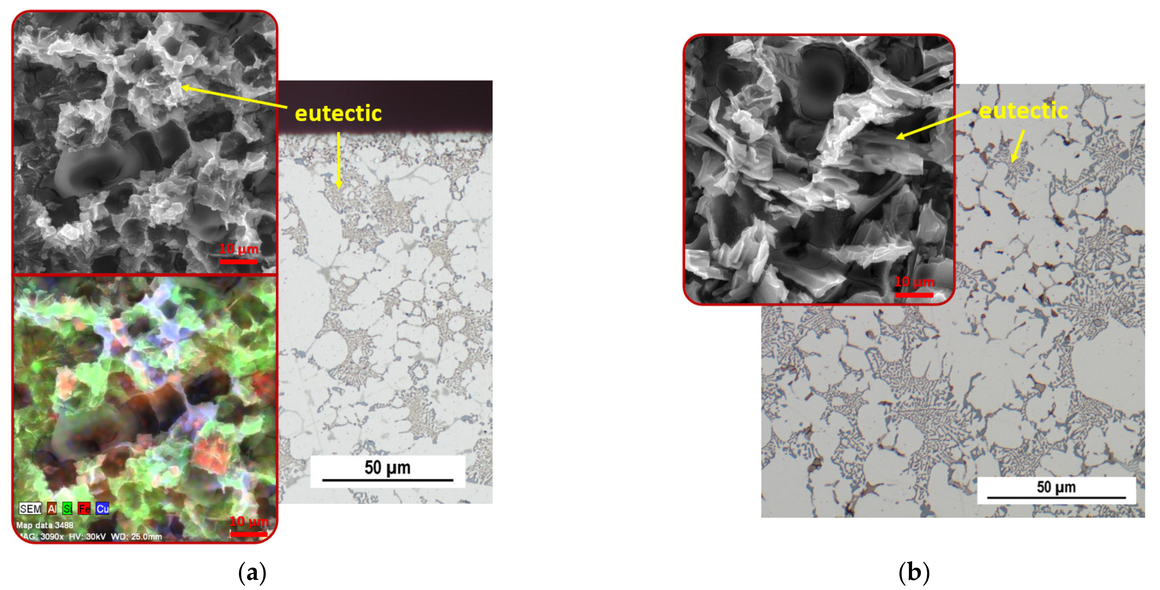
Metals 11 01084 g004
Figure 5. Images of the structure of the Z55 alloy casting in the cast state; OM, SEM: (a) surface region; (b) central region.
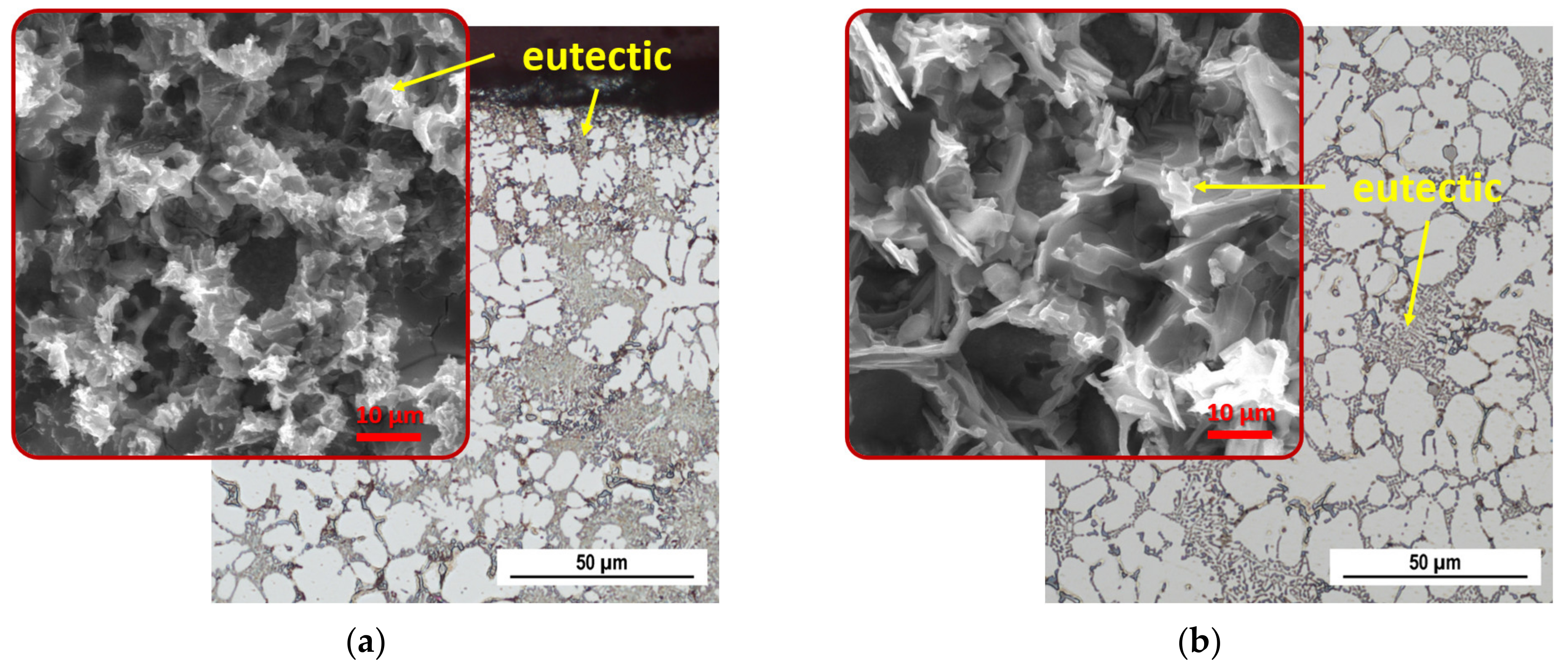
Metals 11 01084 g005
Figure 6. Images of the structure of the Z75 alloy casting in the cast state; OM, SEM: (a) surface region; (b) central region.
Metals 11 01084 g006
Figure 7. Images of the structure of the Z90 alloy casting in the cast state; OM, SEM: (a) surface region; (b) central region.
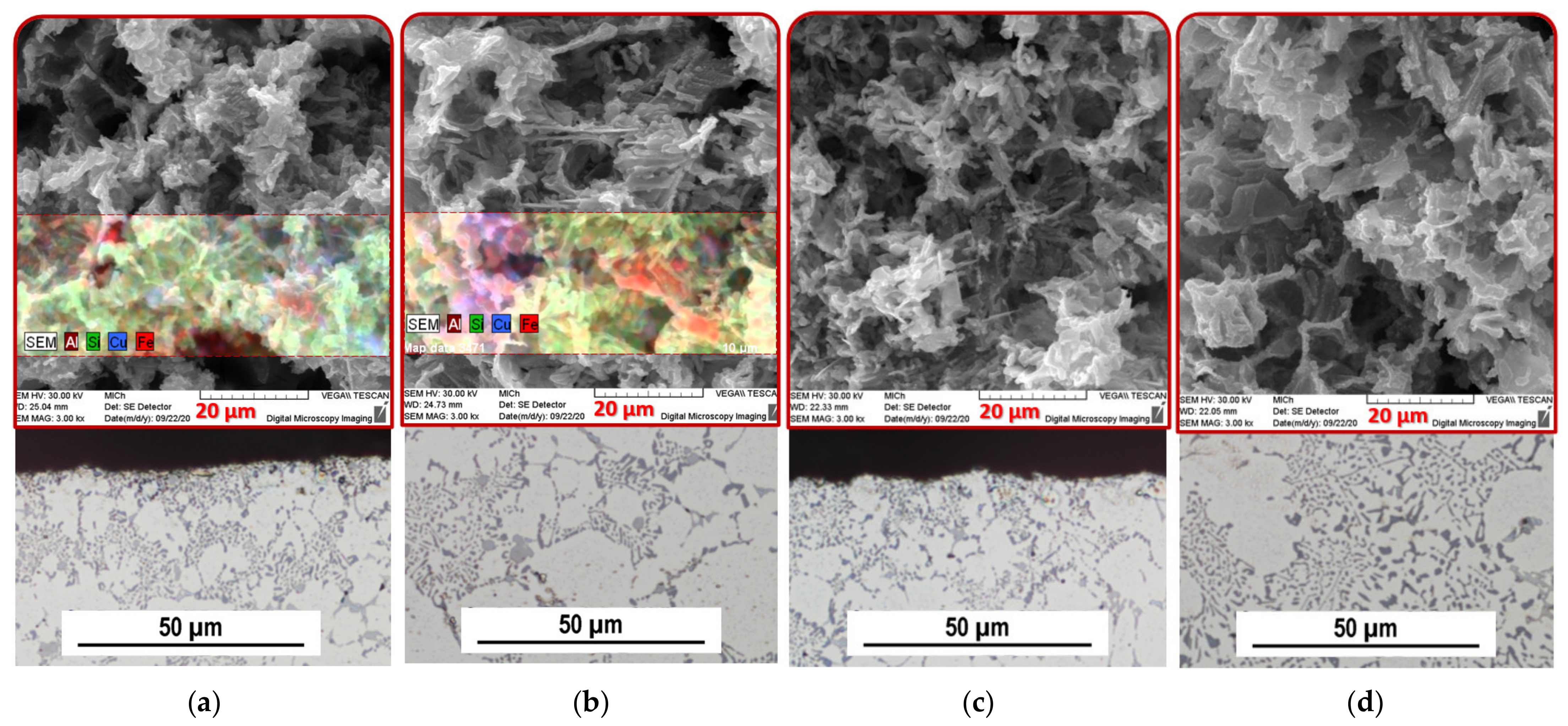
Metals 11 01084 g007
Figure 8. Images of the structure of the castings from the Z10 and Z55 alloys after heat treatment; OM, SEM: (a) Z10 surface; (b) Z10 central region; (c) Z55 surface; (d) Z55 central region.
Metals 11 01084 g008
Figure 9. Images of the structure of the casting from the Z75 and Z90 alloys after heat treatment; OM, SEM: (a) Z75 surface; (b) Z75 central region; (c) Z90 surface; (d) Z90 central region.
Metals 11 01084 g009
Figure 10. Dependence of the primary α-phase microhardness of AlSi9Cu3 alloy on the amount of returnable material in the batch and the measuring position on the specimen.
Metals 11 01084 g010
Figure 11. Checking cuts (incisions) A-A and B-B of castings on the casting at position 1: (a) Location of cuts within the casting; (b) Location of cuts with respect to porosity in the casting.
Metals 11 01084 g011
Figure 12. A-A cut through the casting shown in numerical simulation: (a) Display of hot spots; (b) Display of prediction of the presence of oxides and pores.
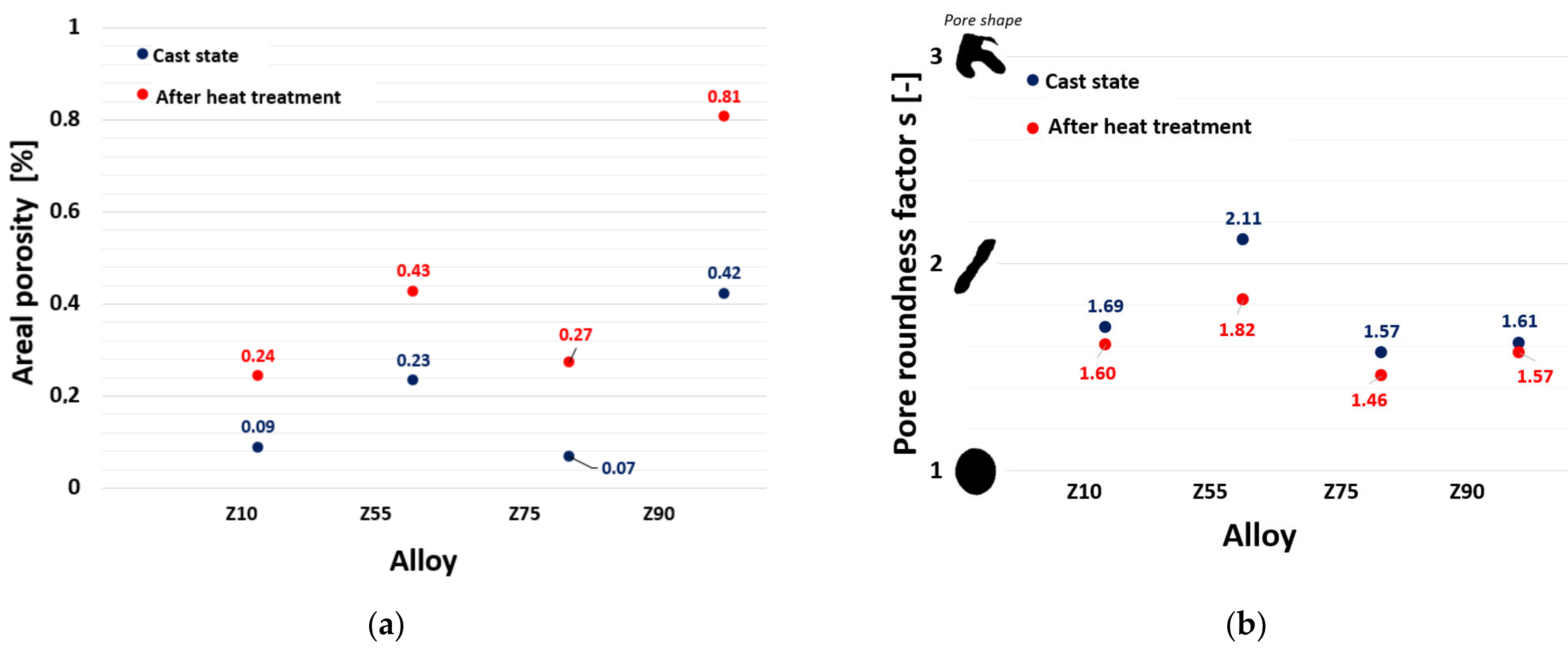
Metals 11 01084 g012
Figure 13. Evaluation of porosity on the A-A cut (incision): (a) Areal porosity; (b) Pore roundness factor.
Metals 11 01084 g013
Figure 14. Evaluation of porosity on the B-B cut: (a) Areal porosity; (b) Pore roundness factor.
Metals 11 01084 g014
Figure 15. Porosity occurring near the casting walls: (a) Numerical simulation showing surface regions with increased presence of oxides; (b) Pores disrupting the geometry of the casting from Z55, after heat treatment.
Metals 11 01084 g015
Table 1. Chemical composition of the alloy (commercial purity) and experimental alloys AlSi9Cu3(Fe) (wt.%).
ElementsSiFeCuMnMgNiTiCr
AlSi9Cu3(Fe)
(Commercial)
9.0550.7462.2820.1840.2270.0750.040.063
Z109.2060.762.0560.2420.3450.0680.0330.023
Z559.6710.7172.1110.1890.1930.0820.040.023
Z7510.930.7682.0120.2250.2340.0850.0330.024
Z9010.40.8222.0060.2210.1490.0780.0350.031
Publisher’s Note: MDPI stays neutral with regard to jurisdictional claims in published maps and institutional affiliations.

