Abstract
In additive manufacturing, powder characteristics play an important role in terms of flowability and densification, which can be improved by the use of spherical powders. In this study, irregular powder was spheroidised by plasma treatment, and the powder properties were measured. Powder characterisation was conducted to determine the morphology, particle size and distribution as well as the flowability. Spherical AISI 304 stainless steel powders were produced by plasma spheroidization, and the efficiency of the spheroidisation process was evaluated. The spheroidisation process resulted in 93% efficiency with a decrease of fine particles (<63 µm) by 22%, while the all the flowability parameters of the powder improved significantly.
1. Introduction
Exploiting the opportunities presented by advanced metal manufacturing technologies requires efficient upstream processes, especially the design and production of raw or feedstock materials. In most cases, unique properties are required from metal powders employed in these technologies [1]. The quality of metal powders used in conventional powder metallurgy processes or in the emerging additive manufacturing process determines the properties of the finished product. The properties of the finished product depend on the character of the base manufacturing process and the process of producing the base powder.
There are different methods of manufacturing metal powders, with each method offering different particle morphologies and chemical purity. The methods include crushing (for brittle materials), machining, mechanical pulverization, slotting, electrolysis, atomization of liquid metal using water, nitrogen, argon or a combination of these and the reduction of metal oxides in hydrogen or in carbon [2]. Different powder manufacturing methods aim to efficiently and economically produce carefully controlled powders with powder properties that specifically suite a particular manufacturing technology. It is, therefore, critical to ensure high quality and inexpensive powders for use in the AM process.
The advent of additive manufacturing technologies using selective laser melting (SLM) and direct energy deposition (DED) requires specific particle size distribution, chemical quality and spherical morphology, which are all important when selecting and/or optimizing a powder for any given process [3,4]. In order to obtain spherical powders, methods such as water atomization, gas atomisation, plasma atomisation and plasma spheroidisation can be employed. Plasma methods produce the highest quality powders with higher roundness and fewer satellite particles compared to gas-atomised powders [5]. Water atomization is known to produce irregular-shaped stainless steel powders that have the capability of being cold pressed in a die, and this powder is known as compacting grade powder [6]. Gas atomization is used to produce spherical stainless steel powders that are used for consolidation by additive manufacturing, hot pressing or extrusion. Additive manufacturing usually requires a high degree of sphericity coupled with appropriate particle size distribution to ensure good flowability and high packing densities [6].
Particle morphology refers to the size, shape and surface roughness of particles. In AM, all of these powder characteristics play a significant role in powder performance, including flowability and packing efficiency. The properties of the powder used for metal-based additive manufacturing, as well as the properties of the resulting bulk metal product, are a necessary condition for industry to be able to select the powder and produce consistent parts with known predictable properties [7,8,9].
Stainless steels are well known for their resistance to corrosion, creep and high temperature applications. There is an increasing demand of powder metallurgy components made from stainless steel in a variety of applications, including aerospace, automotive and chemical processing fields [3]. The AISI 304 austenitic stainless steel investigated in this study has excellent weldability, producing products with high strength, high ductility and good corrosion resistance in the natural environment. Metal powder and additive manufacturing technology offer new product opportunities. The specific alloy composition with suitable morphology of the powder particles allows engineers to explore innovative design and fabrication technologies.
The application of additive manufacturing in the production of structural parts is based on the comparison of its cost against the cost of other methods of forming of the same structural part and the influencing factors’ superiority and efficiency in which the starting raw materials are utilized. In this study, a consideration for efficiently producing spherical additive manufacturing powder from irregular powder was investigated.
2. Materials and Methods
The Tekna’s 15 kW induction plasma system (Tekna Plasma Systems Inc., Sherbrooke, QC, Canada) at Necsa, South Africa, was used to spheroidise the irregular powder. Figure 1 shows a simple schematic representation of the system. The plasma system uses a PL-35M induction torch, and it is intended to be used to process batch samples of powders up to 400 mL or 3 kg, depending on the bulk density of the powder. The plasma torch is mounted on a reactor chamber equipped with a catch-pot for the collection of the solid spheroidised particles. During plasma treatment, fine particles evaporated resulting in the formation of fine deposits that were also collected at the bottom of the cyclone and the filter. Deposition of densified/spherical particles and fine particles also occurred on the reactor chamber.
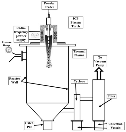
Figure 1.
Schematic of the TEKNA 15 kW experimental setup.
The powder feed rate was adjusted for each size fraction ranging from 1.3 to 1.52 kg/h using a carrier gas (Ar) at a flow rate of 2 standard litres per minute (slpm), and the average processing power was also varied from 7.6 to 9.3 kW·h/kg. The chosen parameters ensured spheroidisation ratios higher than 85% for all powder fractions treated. All products obtained using large batch samples in Table 1 were plasma treated, and all products underwent a cleaning cycle done in batch mode, using a high-power ultrasonic water bath and wet sieving, followed by a drying cycle. Combined with the spheroidisation and densification process, powder cleaning by sonification is a patented process by Tekna (US 7 572 315 B2) [10]. For this study, the powder cleaning process was done using laboratory equipment, based on the Tekna patented method.

Table 1.
Particle size distribution of the feed powder for the bulk test.
The AISI 304 stainless steel (AISI 304 SS) powder used was supplied by Hoganas in Sweden, with an elemental composition specified according to AISI standard as shown in Table 2. The parameters for spheroidisation and densification plasma process were derived from a trial test using 130 g of irregular powder sieved into six size fractions of an average of 20 g per fraction. For the bulk test, irregular powder weighing 3723.3 g was also sieved into similar size fractions. The plasma-treated powders from both tests were collected from the catch-pot of the reactor chamber, while the fine deposits were collected from the reactor chamber as well as from the collection pots attached to the cyclone and the filter. The total weight of spheroidised powder collected was calculated as the sum of the catch-pot powder and the fine deposits.
Table 2.
Typical elemental composition, in wt.%, of AISI 304 type austenitic stainless steel.
The as-received and spheroidised powders were characterised using the JEOL JSM 6510 scanning electron microscope equipped with an EDS detector manufactured by JEOL Hertforshire, UK. Particle size analysis was done with a Bluewave Microtrac laser diffraction particle size analyser, and the particle shape was analysed using a Microtrac PartAn SI, AnaTech Suspension Image Analyzer. The Microtrac Bluewave is a laser diffraction technique that is based on the ASTM B 822-10: Standard test method for particle size distribution of metal powders and related compounds by light scattering. Flowability and bulk densities were measured using the Hall flow meter based on the ASTM B213-20: Standard test methods for flow rate of metal powders using the Hall Flowmeter Funnel and ASTM B212-17: Standard test method for apparent density of free-flowing metal powders using the Hall Flowmeter Funnel. Furthermore, a Freeman Technology-FT4 powder rheometer was used to measure the stability, bulk, flow and shear properties of the powders. The stability tests were carried out in a 25 mm × 25 mm vessel, and the compressibility, shear and wall friction tests were done in a 25 mm × 10 mm vessel.
3. Results
The trial test had a feed quantity of 20 g for each size fraction, which was kept equal for all tests. Figure 2 shows the product distribution for 20 g fractions after plasma treatment of a control trial sample. From the graph, it can be seen that the efficiency of plasma treatment depends on the recovery of products from both the catch-pot and reactor walls. The results show that losses are mainly in the small particle size ranges of −38 and 38–45µm. This is due to the evaporation of finer particles at high temperature or their entrapment on areas of the reactor, including the reactor wall, as it is seen that over 50% was recovered from the reactor walls. A different behaviour was observed for larger particle size ranges of 45–63 µm and 63–90 µm where higher recoveries of 70 to 90% were obtained in the catch-pot.
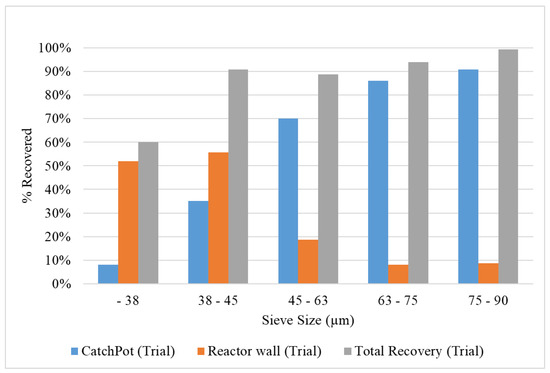
Figure 2.
Product distribution for fractions after plasma treatment of control trial sample.
3.1. Spheroidisation
When plasma treating the bulk sample, the −38 µm and 38–45 µm powders were added together due to the small amount of 38–45µm fraction available. The distribution graph in Figure 3 shows that powders obtained from the catch-pot and from the reactor walls gave recoveries less than 50% for fractions below 75 µm. A sharp rise is observed for the 75–90 µm range that shows a 75% recovery from the catch-pot with only 20% recovery from the reactor wall. This is consistent with the results obtained from the controlled trial experiment that showed the highest recoveries to the catch-pot when processing 75–90 µm size fractions.
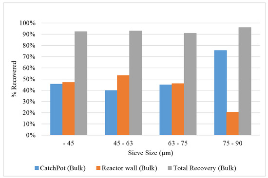
Figure 3.
Product distribution for fractions after plasma treatment of the bulk sample.
For the bulk treatment test, all products from the catch-pot, reactor wall and the cyclone were weighed after plasma treatment, then combined for cleaning and dry sieving. In Table 3, the quantities of the various powder size fractions are shown for the powder before plasma treatment (feed powder), the powder after plasma treatment and the final powder as obtained after cleaning and sieving. More than 90% of all fractions were recovered after plasma treatment with an overall recovery of 93.57% achieved, which is comparable to atomization methods.
Table 3.
Summary of the powder distribution from the bulk test after plasma treatment and the powder quantities after powder cleaning and resieving.
The recoveries after powder cleaning and sieving differed significantly from the feed powder. A decrease for both the 0–38 µm and the 45–63 µm fractions was observed, while an increase for the 63–75 µm and the 75–90 µm fractions was obtained. When comparing the 0–63 µm and the 63–106 µm, it was clear that larger particles were produced during the spheroidisation of powder. The properties of the products depend on the heating times and flow paths of the particles through the plasma taking into account the size, melting point and heat capacity of the particle. The possible cause of the particle increase might be due to the incorporation of evaporated fine particle into large densified particles during the spheroidisation process. The decrease especially in the 45–63 µm fraction indicates that this might have been the reason for the increased 63–106 µm fractions. The change in the size distribution of the powders is clearly illustrated in Figure 4. It is evident that the plasma treatment of the powder resulted in particle growth with a significant increase in the particle sizes larger than 63 µm and a decrease of fine particles (<63 µm) by 22%.
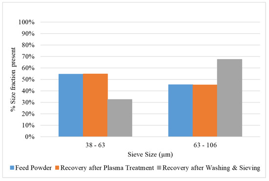
Figure 4.
Size fractions of the powder present in the feed after plasma treatment and after cleaning and sieving.
3.2. Morphology
The as-received 304 stainless steel powder used in this study has an irregular morphology as observed from the SEM images shown in Figure 5a,b. The SEM micrographs of the spheroidised powders collected from the catch-pot in Figure 5c,d show a high-volume fraction of spherically shaped particles, with a smooth surface and the absence of satellites. The spherical powders collected from the catch-pot shown on the insert for Figure 5d indicate dendritic features on the surface. The spheroidised powder particles compare well to atomized powder particles which are characterized by high surface quality, without fracture, adhesion or other defects [11,12]. The products from the reactor walls in Figure 5e,f show high levels of fine particles that attached to the large particles by van der Waals forces with no evidence of satellites fixed to larger particles.
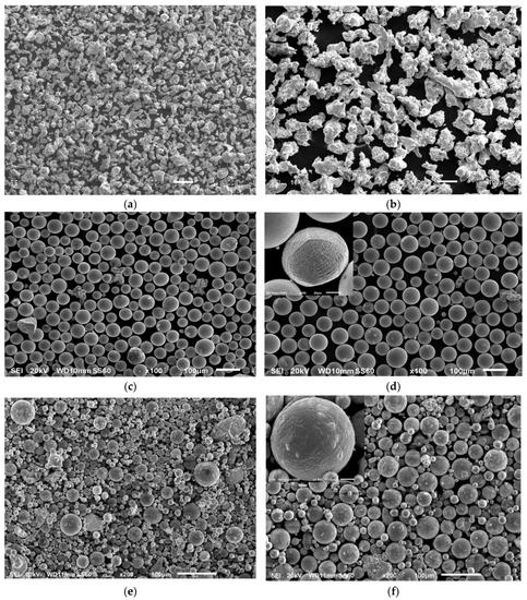
Figure 5.
Low and high magnification micrographs of the AISI 304 SS powder for (a,b) irregular feed powder, and products after the plasma spheroidisation from the (c,d) catch-pot and (e,f) reactor walls for the −63 µm and +63–106 µm size distributions.
Figure 6 shows the cross section of the powders before and after spheroidisation for −63 µm and +63–106 µm. For both the irregular and spherical powders, there is evidence of porosity, shown by blue arrows on the micrographs. In irregular powder, the pores are due to mechanical damage from milling, and in spherical powder, they are due to gas entrapment. The pores obtained bythe spheroidisation process are expected to be similar to those obtained in gas-atomised powder where gas entrapment occurs during solidification of the particles.
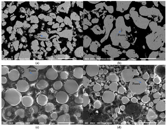
Figure 6.
Micrographs showing cross-section of AISI 304 SS powder for irregular feed powder (a,b) −63 µm and +63–106 µm and for spheroidised powder from catchpot (c,d) for −63 µm and +63–106 µm size powders.
The EDS spectra in Figure 7a–c show a consistent representation of the elements for the austenitic type 304 stainless steel showing the presence of carbon, chromium, nickel, silicon and iron, which is the primary metal. The measured composition from eds are shown in Table 4. However, manganese was not picked up, which would be about a 2% weight fraction of the steel. In stainless steel, manganese is added as a γ-stabilizer similar to the nickel alloy. The as-received powder in its irregular form, together with the product spherical powder from the catch-pot and reactor walls, shows the presence of oxygen. The oxidation resistance of 304 stainless steel is due to the high Cr content that is greater than 18 wt.%, which forms a tight adherent chromia (Cr2O3) surface film [13]. The Si also plays a significant role on oxidation resistance because of the formation of the SiO2 between the base metal and external chromia scale [14]. It is possible that the silicon oxide concentration increased on the Rwall powders due to the heating effect of the plasma treatment of finer particles with larger surface area for the reactions to occur. Particle oxidation occurs while solidifying is ongoing in-flight within the reactor. It is evident that when the Si composition is increased, the Cr composition is low for products on the Rwall, while the inverse is true for the catch-pot product.
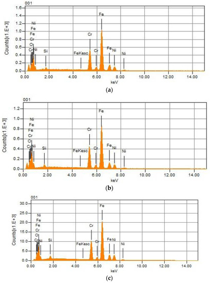
Figure 7.
EDS analysis of the (a) irregular feedstock, and products after the plasma spheroidisation from the (b) catch-pot and (c) reactor walls.
Table 4.
The elemental composition, in wt.%, of the steel and foreign objects detected in the reactor walls.
3.3. Particle Size Analysis
The powders were characterised for particle size and particle size distribution, and the results are shown in Figure 8. The coarse powders show a comparably similar particle size distribution with the spherical powder having more particles in the 60–100 µm compared to the irregular powder. The fine powders on the other hand show a shift in the distribution, with less particles in the −45 µm for spherical powder compared to the irregular powder.
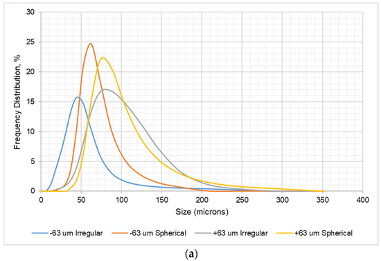
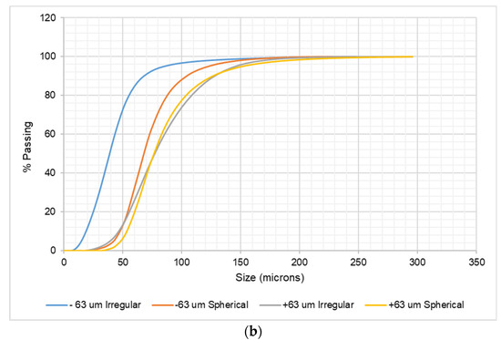
Figure 8.
(a) The frequency and (b) cumulative distribution curves for AISI 304 SS irregular and spheroidised powder.
The cumulative curve in Figure 9 demonstrates the three diameters corresponding to 10% (D10), 50% (D50) and 90% (D90) of the cumulative distribution, where D50 represents the median values. These values are summarized in Table 5. The irregular powder has a median value of 40 µm and 77 µm for the finer and coarser fractions, respectively, while the spherical powder has 56 µm and 76 µm for the finer and coarser fractions. It is clear from the graph that the coarse powders have a closely similar particle size range, and the fine powder has a slightly varying size range. The shift in the particle size is evidence of the absence of the fine powders that were stuck on the reactor wall.
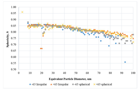
Figure 9.
The sphericity index for untreated and plasma treated powder.
Table 5.
The summary of the powder distribution and shape of the spheroidised powder.
Given the PSD range, the sphericity characterises the particle shapes quantitatively, as depicted in Figure 8 and averaged in Table 5. This sphericity index may vary between 0 and 1, and the smaller the value, the more irregular the shape of the particle [15]. The powder particles in the size range above 63 µm were more angular and had a sphericity below 0.8, while finer fractions had a sphericity above 0.8. This would be expected to affect the flow characteristic of the powder particles.
3.4. Powder Flow Properties
Table 6 shows the flow rate and apparent density properties of AISI 304 SS powder obtained from the Hall Flowmeter Funnel measurements. The results indicated a significant increase in powder flowability and packing characteristics after plasma treatment for both the −63 µm powder and the +63–106 µm powder fractions. The flow rate for −63 µm powder was increased by 32%, while 63–106 µm powder increased by 61%. In SLM processes, high flowability tends to be favourable for reproducible deposition of each powder layer with higher powder packing density [15]. The coarse +63–106 µm powder has higher flowability and higher apparent density values than the fine −63 µm powder. The flowability value shows that the coarse powder flows better than the fine powder, while the apparent density of the coarse powder was also higher than the fine powder, indicating that the coarse powder packed better, occupying a smaller volume for the same amount of powder.
Table 6.
Summary of AISI 304 SS flowability results.
3.5. Stability Index Test
The stability test was done to determine if the powders’ physical properties changed during handling and testing. The changes can be brought about by powder agglomeration, deaeration, segregation, moisture uptake, etc. [16]. The results obtained were 1.06 ± 0.02 units for irregular −63 µm and 0.99 ± 0.003 units for spherical −63 µm. The coarse powder fractions were 1.14 ± 0.09 for irregular +63–106 µm and 1.01 ± 0.01 for spherical +63–106 µm. Powders are considered stable if their values are between 0.9 and 1, meaning all powders in this study are stable, ruling out the possibility of any change in particle size. The analysis was made on product from the catch-pot, which generally showed no satellites that may have attached to the surface of the other particles or any impurities.
3.6. Compressibility Test
The compressibility results shown in Figure 10 present a measure of change in volume in response to a change in applied normal stress from 1 to 15 kPa. The spherical powders show a higher compressibility than irregular powder, typical of low cohesive powders with less interlocking capabilities [17]. The high compressibility can lead to minimal pores formed after additive manufacturing owing to the high packing and density achieved and the ease of scraping specifically in the powder bed AM process. The fine powder had a higher compressibility than the coarse powder.
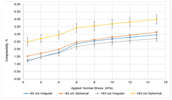
Figure 10.
FT4 compressibility as a function of normal stress.
3.7. Shear Test
Typical results of the shear test are plotted on a Mohr’s circle as shown in Figure 11. The following parameters can be obtained from the shear test: angle of internal friction AIF°, angle of internal friction at steady-state flow AIF(S)°, effective angle of internal friction AIF(E)°, cohesion (C), minor consolidation stress (MCS), unconfined yield strength (UYS) and the major principal stress (MPS). Furthermore, the flowability indexes ffc/Relj and Relp can be derived from MCS, UYS and MPS [9,10].
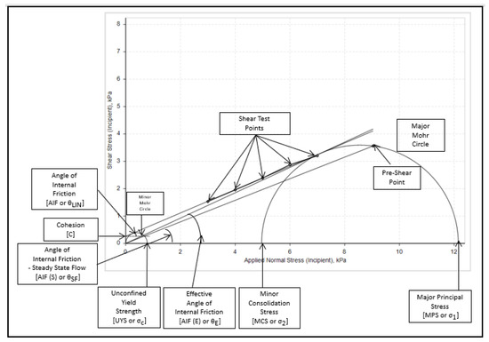
Figure 11.
Shear test and yield locus classification.
The rate of flow of the powder (ffc/Relj) is the flowability index as derived by Jenike [11,18]. It is obtained as a ratio of the major principal stress (MPS) and the unconfined yield strength. All the powders in this study show a value > 10, indicating that the powders are all free flowing according to the Jenike classification in Table 7.
Table 7.
Jenike classification of powder flowability (Adapted from ref. [19]).
The cohesion results are shown in Table 8 below. Cohesion strength is a measure of the resistance of powder to flow. The shear test results show that the irregular −63µm fine powder is more cohesive at 0.38 kPa than the spherical +63–106 µm powder at 0.27 ± 0.02 kPa. Faceted shapes in the irregular powder contribute to the resistance to shear between particles, resulting in high cohesion. Furthermore, a comparison between the fine and coarse powders for both spherical and irregular powders shows that the fine powders are more cohesive at 0.27 to 0.38 kPa than the coarse powders at 0.19 to 0.2 kPa, respectively. Low cohesion is mostly beneficial in powder bed additive manufacturing to enhance the scraping action used to spread the powders, making the spherical powders better suited for that process [20]. The extent of the benefit of low cohesion in powder bed additive manufacturing increases when coarse powders are used compared to finer powders. The tolerance requirement in terms of roughness and wall thickness in powder bed fusion (PBF), however, limits the process to using finer power.
Table 8.
Powder flow characteristics.
It is evident from the results that all the samples are free flowing at ffc > 10, with flowability improved in fine powders when particle morphology changed from irregular to spherical as corroborated by the Hall flow results. This is due to the reduced degree of cohesion between particles brought about by the mechanical interlocking of irregular particles. The small degree of change in flowability between the coarse powders could be due to the similarities in the circularities of these powders as confirmed in Table 5. Due to the high flowability index (ffc) obtained from all the results, it is evident that both the irregular and spherical powders can be used in additive manufacturing, particularly in direct metal deposition.
3.8. Friction Test
Particle–particle friction can be determined from the effective angle of internal friction AIF(E)°, which is a measure of shear resistance between particles in a powder. The irregular powder gave a larger angle of internal friction of 27 to 30°, while spherical powder was less at 20 to 22°. This is expected, as the irregular particles interlock and increase its resistance to flow due to the mechanical bonds formed. The difference observed between coarse and fine powders also indicated a higher AIF(E)° from the coarser fractions. There was a small difference in flow between the fine and coarse powders for the same particle morphology, with fine powder having a higher resistance to flow, as is expected of fine powders. The low resistance to flow observed for the spherical powders can lead to the minimization of interparticle friction and breakage when flowing through the hoppers and make it easy for powder to flow when scraping in powder bed AM [21]. It is evident that the spheroidisation largely improves the flow of powder, and the improvement is less significant with a change in particle size.
The wall friction angle (WFA°) is the coefficient of friction between particles and the contact surface obtained from the wall friction test. This is a measure of the sliding resistance between a surface and a powder. It affects the discharge behaviour of the powders in hoppers. It particularly affects the flow through the feeder nozzles in direct energy deposition AM. The WFA° for the −63µm irregular powder was 25.5 ± 0.2° and for the −63 µm spherical powder was 13.9 ± 0.1°. A larger WFA° represents a higher resistance to flow between powder and the wall; in this case, the irregular powder shows higher resistance to flow than the spherical powder. This is due to the irregular nature of the powder surface that tends to interlock with a surface more than the spherical powder, increasing friction [22]. A comparison of the fine +45–63 µm and +63–75 µm spherical powders shows a high WFA° for the fine powder at 13.9 ± 0.1, and that of 12.5 ± 0.05 for the coarse powder. The fine powder shows a slightly higher resistance to flow than the coarse powder. This is expected, as fine powder tends to be more cohesive than coarse powder and would tend to stick to a surface more.
The particle morphology had the largest contribution to the resistance to flow between powder and a surface compared to particle size for these results. The successful spheroidisation of metal powder by means of plasma techniques presents the convenience of both material handling and manufacturing. These benefits include: more fluidity, increased powder pack density, reduction of internal cavities and fracture surfaces, changes in morphology resulting in lower frictional forces between particles and less contamination during pneumatic transport of particles.
4. Conclusions
The spheroidisation technology demonstrated the production of spherical powders of 304 stainless steel from irregular powder. The spheroidisation process produced recoveries of up to 92%. The spheroidisation resulted in a decrease of fine particles (<63 µm) by 22%, while all the flowability parameters of the powder also improved significantly.
Spheroidisation improves the flow properties of powders, making powders more amenable to additive manufacturing where powder flow is critical for its success to build. Due to the high flowability index FF, it can also be concluded that both the irregular and spherical powders can be used in additive manufacturing, particularly in direct metal deposition.
The plasma setup used for this work is a lab-scale system, and for this reason, the efficiency of the process cannot be used directly to determine whether such a process will be economically viable. However, Tekna Plasma Systems Inc., Canada, do manufacture pilot and commercial scale plasma spheroidisation systems. The economic aspects of spheroidisation for producing powder for additive manufacturing are currently under investigation and not covered in this paper.
Author Contributions
Conceptualization, S.C., L.C.T. and S.H., methodology, S.C., L.C.T., H.B., S.H., N.K.M., T.M.M., T.M. and M.L.; validation, S.C., L.C.T., H.B., N.K.M., T.M.M., T.M. and M.L.; formal analysis, S.C., L.C.T., H.B., N.K.M., T.M.M., T.M. and M.L.; investigation, H.B., N.K.M., T.M.M., M.L. and T.M.; resources, L.C.T., S.C., H.B. and S.H.; data curation, H.B., T.M. and M.L.; writing—original draft preparation, L.C.T. and S.C.; writing—review and editing, S.C., L.C.T., H.B., S.H., N.K.M. and T.M.M.; visualization, S.C. and L.C.T.; supervision, L.C.T., S.C., H.B. and S.H., project administration, L.C.T.; funding acquisition, L.C.T., H.B. and S.H. All authors have read and agreed to the published version of the manuscript.
Funding
This research was funded by the Department of Science and Innovation, project number DST/CON 0005/2018 “4D Hybrid manufacturing” and “the Advanced Materials Initiative (AMI)”, project number DSI/CON 0000/2020, for the plasma treatment of powder.
Institutional Review Board Statement
Not applicable.
Informed Consent Statement
Not applicable.
Data Availability Statement
The data presented in this study are available on request from the corresponding author. The data are not publicly available as they form part of an ongoing study.
Acknowledgments
The Nuclear Materials Group at Necsa, especially Milton Makhofane is thanked for their contribution during the plasma spheroidisation experiments.
Conflicts of Interest
The authors declare no conflict of interest. The funders had no role in the design of the study; in the collection, analyses, or interpretation of data; in the writing of the manuscript; or in the decision to publish the results.
References
- Bao, Q.; Yang, Y.; Wen, X.; Guo, L.; Guo, Z. The preparation of spherical metal powders using the high-temperature remelting spheroidization technology. Met. Des. 2021, 199, 1–10. [Google Scholar]
- Narasimhan, K.; Amuda, M.O.H. Powder Characterization. In Metal Powder; Reference Module in Materials Science and Materials Engineering; Elsevier: Amsterdam, The Netherlands, 2017. [Google Scholar] [CrossRef]
- Kaplan, M.A.; Kirsankin, A.A.; Smirnov, M.A.; Kalaida, T.A.; Baranov, E.; Ustinova, Y.O.; Sevostyanov, M.A. Properties of spherical stainless steel powders. In Proceedings of the Fourth Interdisciplinary Scientific Forum with International Participation “New Materials and Promising Technologies”, Moscow, Russia, 27–30 November 2018. [Google Scholar]
- Kriewall, C.S. Characterization and Tailoring of Powder Used in Additive Manufacturing and Plasma Spheroidization. Master’s Thesis, Missouri University of Science and Technology, Rolla, MO, USA, 2018. [Google Scholar]
- Sun, P.; Fang, Z.Z.; Zhang, Y.; Xia, Y. Review of the Methods for Production of Spherical Ti and Ti Alloy Powder. JOM 2017, 69, 1853–1860. [Google Scholar] [CrossRef] [Green Version]
- Fedina, T.; Sundqvist, J.; Powell, J.; Kaplan, A.F. A comparative study of water and gas atomized low alloy steel powders for additive manufacturing. Addit. Manuf. 2020, 36, 10165. [Google Scholar] [CrossRef]
- Tshabalala, L.; Mathe, N.; Chikwanda, H.K. Characterization of Gas Atomized Ti-6Al-4V Powders for Additive Manufacturing. Key Eng. Mater. 2018, 770, 3–9. [Google Scholar] [CrossRef]
- Markusson, L. Powder Characterization for Additive Manufacturing Processes. Master’s Thesis, Luleå University of Technology, Luleå, Sweden, 2017. [Google Scholar]
- Van Laar, J.H.; Bissett, H.; Barry, J.C.; Van Der Walt, I.J.; Crouse, P.L. Spheroidisation of iron powder in a microwave plasma reactor. S. Afr. J. Sci. Technol. 2017, 36. [Google Scholar] [CrossRef]
- Bissett, H.; van der Walt, J.I.; Havenga, J.L.; Nel, J.T. Titanium and zircon metal powder spherodization by thermal plasma processes. J. South. Afr. Inst. Min. Metall. 2015, 115. [Google Scholar] [CrossRef]
- Clayton, J.; Deffley, R. Metal Powders for Additive Manufacturing Performance and Consistency Required in Demanding. Met. Powder Rep. 2014, 69, 14–17. [Google Scholar] [CrossRef]
- Jiang, X.; Che, X.; Tian, C.; Zhu, X.; Zhou, G.; Chen, L.; Li, J. Preparation of 304 Stainless Steel Powder for 3D Printing by Vacuum-Induced Multistage Atomization. Front. Mater. 2021, 7. [Google Scholar] [CrossRef]
- Huang, X.; Xiao, K.; Fang, X.; Xiong, Z.; Wei, L.; Zhu, P.; Li, X. Oxidation behavior of 316L austenitic stainless steel in high temperature in air with long term exposure. Mater. Res. Express 2020, 7, 066517. [Google Scholar] [CrossRef]
- Dunning, J.S.; Alman, D.E.; Rawers, J.C. Influence of Silicon and Aluminum Additions on the oxidation resistance of a lean-chromium stailnless steel. Oxid. Met. 2002, 57, 409–425. [Google Scholar] [CrossRef]
- Choi, J.-P.; Shin, G.-H.; Lee, H.-S.; Yang, D.-Y.; Yang, S.; Lee, C.-W.; Brochu, M.; Yu, J.-H. Evaluation of Powder Layer Density for the Selective Laser Melting (SLM) Process. Mater. Trans. 2017, 58, 294–297. [Google Scholar] [CrossRef] [Green Version]
- Chikosha, S.; Mahlatji, L.M.; Chikwanda, H.K. Characterisation of Titanium Powder Flow, Shear and Bulk Properties Using the FT4 Powder Rheometer. Adv. Mater. Res. 2014, 1019, 218–224. [Google Scholar] [CrossRef]
- Divya, S.; Ganesh, G. Characterization of Powder Flowability Using FT4—Powder Rheometer. J. Pharm.Sci. Res. 2019, 11, 25–29. [Google Scholar]
- Clayton, J.; Dawes, J.; Langley, C. Optimizing Metal Powders for Additive Manufacturing: Exploring the Impact of Particle Morphology and Powder Flowability. Met. Powder Rep. 2017, 69, 1–5. [Google Scholar]
- Technology, F. Additional Parameters Derived from Shear Cell Data. 2013. Available online: https://www.freemantech.co.uk/learn/powder-rheology (accessed on 11 March 2021).
- Wei, W.; Wang, L.; Chen, T.; Duan, X.; Li, W. Study on flow properties of Ti6Al4V powders prepared by radio frequency plasma spheroidization. Adv. Powder Technol. 2017, 28, 2431–2437. [Google Scholar] [CrossRef]
- Sutton, A.; Kriewall, C.; Leu, M.; Newkirk, J. Powders for additive manufacturing processes: Characterization techniques and effects on part properties. In Proceedings of the 27th Annual International Solid Freeform Fabrication Symposium, Austin, TX, USA, 8–10 August 2016. [Google Scholar]
- Ewsuk, K.G. Powder granulation and compaction. In Encyclopedia of Materials: Science and Technology; Pergamon Press: Oxford, UK, 2001. [Google Scholar]
Publisher’s Note: MDPI stays neutral with regard to jurisdictional claims in published maps and institutional affiliations. |
© 2021 by the authors. Licensee MDPI, Basel, Switzerland. This article is an open access article distributed under the terms and conditions of the Creative Commons Attribution (CC BY) license (https://creativecommons.org/licenses/by/4.0/).