Abstract
During Laser Powder-Directed Energy Deposition (LP-DED), many complex phenomena occur. These phenomena, which are strictly related to the conditions used during the building process, can affect the quality of the parts in terms of microstructural features and mechanical behavior. This paper investigates the effect of building parameters on the microstructure and the tensile properties of AISI 316L stainless-steel samples produced via LP-DED. Firstly, the building parameters were selected starting from single scan tracks by studying their morphology and geometrical features. Next, 316L LP-DED bulk samples built with two sets of parameters were characterized in terms of porosity, geometrical accuracy, microstructure, and mechanical properties. The tensile tests data were analyzed using the Voce model and a correlation between the tensile properties and the dislocation free path was found. Overall, the data indicate that porosity should not be considered the unique indicator of the quality of an LP-DED part and that a mechanical characterization should also be performed.
1. Introduction
Laser Powder-Directed Energy Deposition (LP-DED) is an Additive Manufacturing (AM) process that uses a laser beam to melt a metallic powder which is directly blown in specific areas of the building volume. The LP-DED building process has been recently used in several fields such as aeronautical, petrochemical, automotive, and power generation [1]. The main advantages of this AM technique are the possibility of producing large parts, functionally graded materials, and repairing worn components [2].
The LP-DED technique requires using a proper combination of process parameters to obtain high-quality parts [3]. When a new powder needs to be processed, it is therefore essential to define main parameters such as the powder feed rate (F), the laser power (P), the scanning speed (v), and the hatch and layer spacings (dX and dZ) [3]. These parameters influence not only the morphology and the stability of each track but also their solidification behavior and resulting microstructure [4]. The LP-DED building parameters may affect, in fact, the thermal gradient (G), the growth rate (R), and the intensity of the fluid flows in the melt pool [5,6]. These phenomena strongly influence the solidification mode and the consequent microstructure.
AISI 316L stainless-steel has been widely used in the LP-DED process because it finds applications in many industries. Therefore, the production of many components via LP-DED has been studied lately in the literature [7]. Because of these reasons, the LP-DED processability and the properties of this alloy have been widely investigated in recent years [8,9,10,11,12,13,14,15].
Boisselier et al., for example, researched the effect of 316L powder properties on the samples’ quality and suggested that the process parameters need to be optimized for each powder batch as the particle morphology affects the flowability and the laser powder interaction [8]. Saboori et al. considered the effect of powder reuse on the microstructure of 316L samples and showed that a large number of Si- and Mn-rich oxides were found in samples built with reused powder, due to oxygen enrichment during the reuse [9]. The presence of these large inclusions remarkably affected the tensile properties of the samples and in particular their ductility. Eo et al. analyzed the fine oxygen-rich inclusions found in LP-DED 316L samples and identified a correlation between their content and the building parameters used [10]. Yadollahi et al. studied the effect of the time interval on the microstructure of 316L LP-DED samples [11]. Their study underlined the role of thermal history and in particular, of the cooling rate on the microstructure of the part in terms of grain size and morphology. Their findings indicated that longer time intervals cause a higher cooling rate and, consequently, a finer microstructure. The effect of the thermal history was also studied by Mukherjee et al., who focused on the effects of the part geometry and orientation on 316L LP-DED samples [12]. In their study, the authors indicated that a higher cooling rate associated with larger areas led to a finer microstructure and cracks. Zheng et al. studied the evolution of the microstructure and the mechanical behavior of 316L processed by LP-DED [14]. The authors illustrated the complexity of the microstructure and found correlations with the high thermal gradient, the fluid flow that arises in the melt pool, and the intrinsic heat treatment which the material undergoes. The authors also investigated the effect of the laser focus and showed that it strongly affects the geometry of the part.
In most of these studies, however, the authors used parameter sets that were selected according to the users’ experience or based on a trial and error approach, mainly using the porosity of the samples as a selection criterion [11]. As a result, the effect of the building parameters on the microstructure and properties was poorly investigated.
Therefore, it is important to define the effect that LP-DED building parameters have on microstructural features such as Primary Cellular Arm Spacing (PCAS), grain size, and texture of 316L parts produced. The present work focuses on the impact of the LP-DED building parameters on the microstructure and mechanical properties of 316L stainless-steel samples. Furthermore, the Voce model was applied to find a correlation between the tensile properties and dislocation free path.
2. Materials and Methods
A commercial AISI 316L gas atomized powder was used to produce steel samples by LP-DED. The powder contains mainly spherical particles of about 80 µm, however, some irregular particles, a few satellites, and some fine particles were also found (Figure 1a). The powder particle size distribution was evaluated using a laser granulometry Analysette 22 Compact model (FRITSCH GmbH, Markt Einersheim, Germany) and is reported in Figure 1b. The particles have a d10 = 54 µm, d50 = 79 µm, and d90 = 110 µm. It is important to underline that a different producer provided this powder with respect to the one used in previous works by some of the authors [7,9].
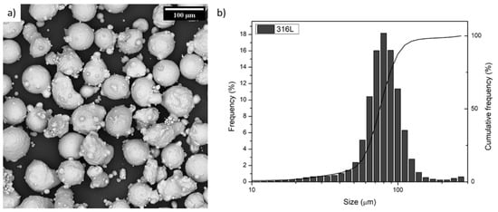
Figure 1.
(a) SEM image and (b) particle size distribution of the as-received 316L powder.
The samples were produced using an LP-DED prototype built by Prima Additive (a division of Prima Industrie S.p.A). This system is composed of a 3-axis CNC unit with four coaxial multi-nozzles and an ytterbium fiber laser with 3 kW maximum power and a laser spot value of 1.3 mm. The steel powder was delivered using a commercial powder feeder that employs a rotating disk to regulate the powder flow. For all experiments, N2 was used as a carrier gas and central shielding gas with 3 L/min as the flow rate. The samples were built on 120 × 120 × 8 mm3 316L stainless-steel platforms.
To optimize the parameters, in a first experimental step, Single Scan Tracks (SSTs) with 40 mm length and different P and v combinations were produced using a constant powder feeder rotation. Two SSTs per each P-v sets were built varying the scan tracks deposition sequence.
All SSTs were cut in their center, mounted in hot resin, and polished down to 0.03 µm using colloidal silica. The SSTs’ polished cross-sections were analyzed using a Leica DMI5000 M (Leica, Wetzlar, Germany) optical microscope. The beads geometrical features were then measured using the ImageJ software (version: v1.51J8, National Institutes of Health, Bethesda, MD, USA).
Subsequently, four small bulk samples (20 × 10 × 15 mm3) have been built using two sets of building parameters selected based on the SSTs results. These parameter sets are reported in Table 1 and will be named low power (LP) and high power (HP). The dX and dZ values were selected according to the SST’s size to keep the same hatch and growth overlap for both samples. The deposition strategy used is the 0/90° having a bidirectional scanning in each layer. Furthermore, a contour was also deposited with the same parameters prior the deposition of each layer in order to assure a geometrical stability of the part.

Table 1.
Set of building parameters used for bulk samples.
The bulk samples were also cut in their center along the X–Z plane, ground with SiC papers to 4000 grit, and polished with diamond suspensions and colloidal silica down to 0.03 µm. The dimensions of the cubes were measured and compared with the nominal ones. The samples’ cross-sections were then analyzed by means of the optical microscope to detect the defects such as oxides and pores. The percentage of defects (i.e., porosity) was evaluated by image analyses using the ImageJ software. On each sample, 40 images were taken at 100× magnification equally spaced in order to cover about 50% of the whole surface.
An SEM TESCAN S9000G (Tescan Company, Brno, Czech Republic) equipped with an Electron Backscatter Diffraction (EBSD) detector was used to analyze the grain morphology. For the analyses, the samples were tilted at 70°, and the SEM operated at 20 keV and 10 nA using a step size of 5 µm.
After these analyses, the samples were etched using a Kalling’s n. 2 solution for 10 s and observed at the optical microscope to evaluate the dZ value and compare it with the theoretical one. Etched samples were also observed by a Phenom XL SEM (Thermo Fisher Scientific, Waltham, MA, USA) to study the PCAS using the triangle method [9]. The PCAS values were evaluated on 14 images per sample taken at 300×.
Finally, four larger samples (12 × 12 × 93 mm3) were also built with the same sets of parameters. Two tensile samples were extracted from each of these bars as reported in previous works [7] and were tested using a Zwick Z100 tensile machine (Zwick-Roell GmbH & Co. KG, Ulm, Germany) connected to a contact extensometer using 8 × 10⁻³ s−1 as the strain rate. The tensile specimen geometry was based on the ASTM E-8 standard with 4 mm thickness and 25.4 mm as the gauge length. The samples were obtained by milling in order to avoid the surface-related effects as much as possible and analyze the bulk materials’ properties [16].
The results obtained with the tensile tests were also used to assess the strain hardening behavior of the steel samples built with the parameter sets mentioned above. First of all, the engineering stress and strain curves were converted into true-stress (S) and true-strain (e) ones considering that e = ln(1 + ε) and S = σ(1 + ε), respectively.
This transformation was limited only to the uniform plastic deformation zone, i.e., only in that part of the curves between the yield and the maximum strength. The linear portions of the curves can be interpolated using the Voce flow stress model. The derived fitting parameters of the Voce equation (see below Equation (1)) are extremely important since they are strongly related to microstructural features of the investigated material [17].
where A = q/k2, B = Mk2, and C = p. According to the literature [18], M is the Taylor’s factor, q is related to the dislocation free path (λ), k2 is the recovery rate, and p is a material constant. More specifically, q directly correlates with the grain size and dislocation density.
In this work, the Taylor’s factor was considered equal to 3, as also suggested in Yvell et al. for 316L [19]. The parameters mentioned above were derived with a non-linear fitting performed in Origin2018 software using the Levenberg–Marquardt least square method. The fitting quality was measured with the standard R2 calculation and with the average absolute relative error (AARE), which was calculated using (Equation (2)).
where E stands for experimental values, while P for the model-predicted ones.
3. Results and Discussion
In a first experimental step, the most promising P-v sets were selected by SSTs analyses. The morphologies of the SSTs built with different combinations of power and scan speed are reported in Figure 2a. The images clearly show that stable scan tracks were formed in most cases and that both P and v affect their morphology. The figure shows that maintaining a constant powder feeding, high power, and low scan speed lead to larger beads. The use of a high laser power causes higher energy densities, and therefore, the formation of larger melt pools. Larger melt pools implicate larger powder capture, therefore, these parameters are also associated with higher powder efficiency values [20]. Conversely, the effect of the scanning speed is not only correlated to the higher energy density but also to the higher powder deposition reached as the scan speed decreases. The powder deposition represents, in fact, the amount of powder delivered by the carrier gas and can be calculated as F*v.
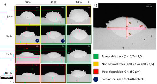
Figure 2.
(a) Representative cross-section images of SSTs built with different combinations of P and v, (b) schematic representation of measurements.
For a more accurate analysis of the tracks and to discern the most promising P-v sets, each SST was measured as shown in Figure 2b. The SST’s quality was defined based on two main aspects: the bead’s growth (G) and the G/D ratio. As previously reported, in fact, the G/D ratio can be a good indicator of the quality of a SST [21,22]. Low values of G/D indicate that the scan is poorly growing and that most of the energy is used for remelting rather than building [23]. High G/D ratios, on the contrary, could indicate a poor interconnection with the previous layers, which might cause porosities and delaminations in bulk components.
The process window was then divided into three areas according to the features as reported in the legend of Figure 2.
As a result of the SSTs analysis, two sets of power and scan speed were selected:
- Low Power (LP): P = 50% and v = 60%
- Low Power (HP): P = 60% and v = 60%
The LP parameters were selected, even if they belong to the orange area of the process window, as they resulted in being the most promising in the optimization of a similar powder described in previous works [7]. Furthermore, the selection of non-optimal P-v set aimed to evaluate the validity of the selected criteria. The HP parameters, on the contrary, were selected as they seemed to be among the most promising ones as they resulted to be the most central in the green area of the process window (Figure 2a). This implies not only that the SSTs were characterized by appropriate G and G/D values but also that slight variations of the thermal conditions that can arise due to the fact that the heat accumulation would not strongly modify the geometrical features.
Based on these data, cubes were built using 0.3 and 0.0 as hatch overlap (XOV) and growth overlap (ZOV), respectively. These values were selected based on the knowledge acquired using similar powders [24]. Furthermore, results reported in the literature suggest to use similar overlap values in order to avoid a strong increase in the layer height from the first scan track to the last one of the layer [25].
Based on the scan geometries, the displacement values (dX and dZ) for each cube were then calculated according to Equations (3) and (4).
where x and x are the overlap distances along the X and Z directions.
A schematic representation of the tracks’ overlaps and displacements is reported in Figure 3.
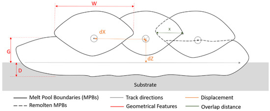
Figure 3.
Schematic representation of two LP-DED layers build with no growth overlap and the 0/90° scanning strategy with bidirectional scanning in each layer.
The optical images of the X–Z cross-sections of the cubes show that the samples are dense and crack free (Figure 4). Images of the defects found in the samples are reported in Figure 4c. Only few fine spherical pores were found in the samples together with some micrometric oxides. The discrimination of pores and oxides by image analyses was impractical; therefore, the defect area was evaluated.
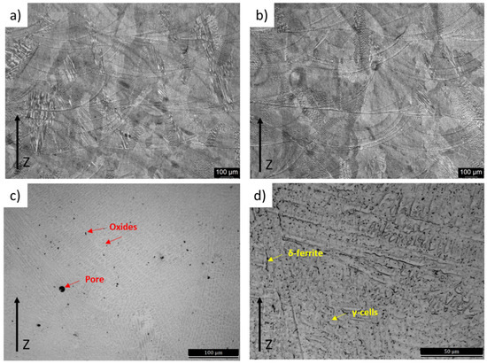
Figure 4.
Optical micrographs of the X-Z cross-section of (a) LP and (b–d) HP sample. The samples are oriented along the building direction. (c,d) High magnification images show the defects and the cellular structure.
The micrographs also display that the microstructures of both samples are made of a network of interconnected melt pools (Figure 4). Within the melt pools, a fine austenitic (γ) cellular structure can be distinguished (Figure 4c,d). In some regions of the cells’ boundaries, δ-ferrite can be detected. The morphology of the cells strongly varies in the melt pool as it follows the thermal gradient [26]. The microstructures of the cubes built with the two sets of parameters did not show relevant differences.
The cubes were analyzed further in detail, and the results are reported in Table 2. From the comparison of the porosity values, the HP set of process parameters seem to be the most promising as it allows to achieve the highest densification. This result is in line with the SSTs maps’ results as the LP scan track, which did not have an optimal G/D value, and implicates lower densification of the bulk sample with respect to the HP one which was characterized by promising geometrical features.
Table 2.
Data of cubes built with high power and low power parameters.
The detailed analyses of the PCAS of the samples revealed that the parameters affect the cell size. In particular, the LP parameters caused the solidification of a finer microstructure characterized by a smaller PCAS value. This reduced size of the cells is due to the higher cooling rate experienced by the LP sample correlated to the reduced energy density value [15,27].
The analysis of the dZ suggested that both samples are growing slightly faster than expected. The total height indicates, in fact, that a slight over-building phenomenon is observed. Under- and over-building are pretty common issues in DED processes [28]. These issues are however, generally not considered to be critical for the building process. The variance in the build height will be autonomously compensated thanks to the appropriate selection of the stand-off and focal distance and to the shape of the laser beam and of the powder stream. Previous studies demonstrated, in fact, that the irregularity of the last layer can be compensated using a stand-off distance lower than the focal length [29,30].
It is important to underline that with simple geometries, the parameters can be easily kept constant during the whole building process. When more complex geometries need to be built, it is important to use specific programs or algorithms able to provide a stable and homogeneous material deposition in the whole component [31].
The EBSD grain orientation maps of the X–Z plane of both samples are reported in Figure 5. The high angle grain boundaries (HAGBs) are indicated in black in the maps. From the maps, it is evident that in both cases, elongated grains were detected. The morphology of the grains indicates that, as expected, they followed the thermal gradient. In both cases, the columnar grains have a length up to about 400 µm and a width of about 20–100 µm. The size of these grains, which in some cases are larger than the dZ values, suggest that they might grow across the melt pools, indicating that an epitaxial solidification arises during the building process [14,32]. This phenomenon is a heterogeneous nucleation which has been observed in many alloys processed by AM [6,33]. In these cases, the grains grow parallel to the thermal gradient with a growth rate (R) which is strictly related to the scan speed used during the building process.
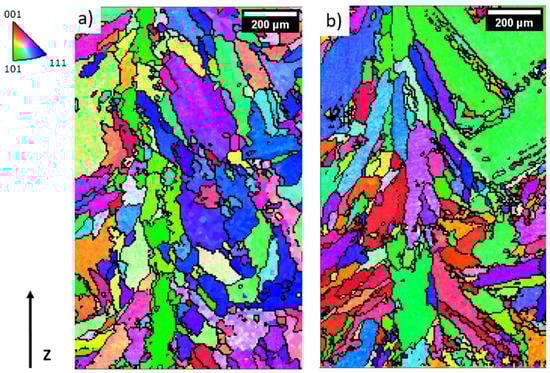
Figure 5.
EBSD inverse pole figure (IPF) maps of 316L samples built with (a) LP and (b) HP parameters. The HAGBs are pointed out in black lines. The corresponding IPF are also highlighted.
No preferential orientation was observed in the samples. As suggested in previous studies, the presence of texture in AM samples is strongly related to the melt pool dimensions and therefore, to the cooling conditions [34]. Stronger textures are generally found in AM samples built with low energy densities (i.e., low power and high scan speed). The poor texture due to high energy density values is generally associated with the stronger turbulence of melt pools caused by the Marangoni flow and the keyhole phenomenon [35].
The stress-strain curves and the tensile properties of the samples are reported in Figure 6 and Table 3 and compared with literature data. The data reveals that the low power samples allow the achievement of higher tensile properties even if slightly higher porosity values characterized the samples. These higher tensile properties could be related to the different microstructural features and, in particular, to the PCAS values. As reported in Table 3, in fact, the LP parameters cause the solidification of finer γ cells. As suggested in previous work, the high Yield Strength (YS) and Ultimate Tensile Strength (UTS) of AM 316L is mainly related to the fine cell size and dislocation densities [36,37]. Tensile properties of 316L samples produced by LP-DED using LP parameters and a powder provided by a different producer are also reported [7]. It can be noted that using different powder but the same parameters lead to very similar tensile performances. For the sake of comparison, the tensile properties obtained in the present study are also compared with other literature data. It can be seen that the UTS values are in line with those obtained in other works and that slightly lower YS were obtained [38]. The comparison with the tensile properties of 316L processed by conventional routes highlights that, as expected, LP-DED samples have higher YS, lower elongation, and similar UTS.
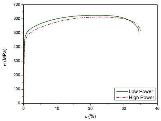
Figure 6.
Representative tensile curves of DED 316L samples built with high power and low power parameters.
Table 3.
Tensile properties of DED 316L samples compared with literature data.
The results of the study performed to analyze the strain hardening behavior are re-ported in Figure 7 and Table 4. The dual-logarithmic plot was used as proposed by other researchers [18,39]. Both curves in the plot show an initial not-linear increasing trend followed by a linear stage. The blue pentagons indicate the transition among the not-linear and linear trend. The last point of the curves represents the ultimate tensile strength, i.e., the last portion of the test before the samples’ geometrical instability.
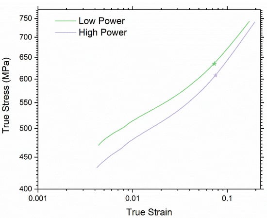
Figure 7.
Log-Log plot of true strain and stress obtained with two parameter sets. The blue pentagon shows where the curve diverges from linearity.
Table 4.
Fitting parameters of Voce model. The R2 and AARE indicates a very good fitting.
The Voce model was used to obtain all the relevant coefficients as previously described. In particular, great attention was given to the parameter q, which is higher in the sample obtained with lower laser power. A higher q value indicates an inferior dislocation free path, which could be compliant with smaller dendritic structures as well as higher dislocation density. Both these hypotheses are in accordance with the previous discussion and experimental results. The higher cooling rate of the LP samples leads to smaller γ cells and probably to a slightly higher dislocation density, leading to the differences in the plastic flow observed and the almost negligible reduction of elongation at break.
4. Conclusions
In this work, AISI 316L stainless-steel samples produced via LP-DED with different sets of parameters were analyzed in terms of SSTs morphology, porosity, geometrical stability, microstructure, and mechanical properties. The main results can be summarized as follows:
- The SSTs morphology can be a good indicator for the selection of appropriate process window that allows the production of dense samples. The cube built with the P-v set indicated by the SSTs analyses and by their geometrical features is characterized by the highest densification. On the contrary, the cube built with P-v set leading to inappropriate G/D values is characterized by slightly higher porosity values.
- Both cubes have a microstructure made of interconnected melt pools containing fine γ cells and some δ-ferrite at the cells’ boundaries. However, the building parameters affect the size of the cells due to the different cooling rates which they undergo.
- The EBSD IPF maps showed that both cubes are characterized by elongated grains that follow the thermal gradient. The grains have length values up to about 400 µm and width of about 20–100 µm. None of the cubes were characterized by textures which is probably due to the high energy density used during the building process.
- The tensile properties indicate that in both cases, high yield and ultimate tensile strengths can be achieved. The comparison of the data indicates that the YS and UTS are related to the building parameters. The samples built with LP parameters are characterized by higher strength even if the microstructural analyses indicated that the samples are characterized by higher porosity values.
- The Voce flow model was effectively used to analyze the plastic behavior of the samples. The fitting results made it possible to determine a smaller dislocation-free path for the LP samples, which is compliant with the finer dendrites of these samples induced by the higher cooling rate.
Author Contributions
Conceptualization, A.A. and G.M.; methodology, E.B.; investigation, E.B.; data curation, G.M.; writing—original draft preparation, A.A.; writing—review and editing, G.M. and E.B. All authors have read and agreed to the published version of the manuscript.
Funding
This research received no external funding.
Institutional Review Board Statement
Not applicable.
Informed Consent Statement
Not applicable.
Data Availability Statement
The data presented in this study are available on request from the corresponding author.
Acknowledgments
The authors would like to acknowledge Erica Librera and Michele De Chirico from Prima Additive (a division of Prima Industrie S.p.A.) for the production of samples and for their support in the experimental activities. The authors would also like to appreciate the assistance provided by Chiara Iervoglini in data analyses.
Conflicts of Interest
The authors declare no conflict of interest.
References
- Thompson, S.M.; Bian, L.; Shamsaei, N.; Yadollahi, A. An overview of Direct Laser Deposition for additive manufacturing; Part I: Transport phenomena, modeling and diagnostics. Addit. Manuf. 2015, 8, 36–62. [Google Scholar] [CrossRef]
- Mudge, R.P.; Wald, N.R. Laser engineered net shaping advances additive manufacturing and repair. Weld. J. 2007, 86, 44–48. [Google Scholar]
- Corbin, D.J.; Nassar, A.R.; Reutzel, E.W.; Beese, A.M.; Kistler, N.A. Effect of directed energy deposition processing parameters on laser deposited Inconel ® 718: External morphology. J. Laser Appl. 2017, 29, 22001. [Google Scholar] [CrossRef]
- Wang, Z.; Palmer, T.A.; Beese, A.M. Effect of processing parameters on microstructure and tensile properties of austenitic stainless steel 304L made by directed energy deposition additive manufacturing. Acta Mater. 2016, 110, 226–235. [Google Scholar] [CrossRef]
- Masoomi, M.; Thompson, S.M.; Shamsaei, N. Laser powder bed fusion of Ti-6Al-4V parts: Thermal modeling and mechanical implications. Int. J. Mach. Tools Manuf. 2017, 119, 73–90. [Google Scholar] [CrossRef]
- Liu, P.; Wang, Z.; Xiao, Y.; Horstemeyer, M.F.; Cui, X.; Chen, L. Insight into the mechanisms of columnar to equiaxed grain transition during metallic additive manufacturing. Addit. Manuf. 2019, 26, 22–29. [Google Scholar] [CrossRef]
- Aversa, A.; Saboori, A.; Librera, E.; de Chirico, M.; Biamino, S.; Lombardi, M.; Fino, P. The Role of Directed Energy Deposition Atmosphere Mode on the Microstructure and Mechanical Properties of 316L Samples. Addit. Manuf. 2020, 34, 101274. [Google Scholar] [CrossRef]
- Boisselier, D.; Sankaré, S. Influence of Powder Characteristics in Laser Direct Metal Deposition of SS316L for Metallic Parts Manufacturing. Phys. Procedia 2012, 39, 455–463. [Google Scholar] [CrossRef]
- Saboori, A.; Aversa, A.; Bosio, F.; Bassini, E.; Librera, E.; De Chirico, M.; Biamino, S.; Ugues, D.; Fino, P.; Lombardi, M. An investigation on the effect of powder recycling on the microstructure and mechanical properties of AISI 316L produced by Directed Energy Deposition. Mater. Sci. Eng. A 2019, 766, 138360. [Google Scholar] [CrossRef]
- Eo, D.; Park, S.; Cho, J. Inclusion evolution in additive manufactured 316L stainless steel by laser metal deposition process. Mater. Des. J. 2018, 155, 212–219. [Google Scholar] [CrossRef]
- Yadollahi, A.; Shamsaei, N.; Thompson, S.M.; Seely, D.W. Effects of process time interval and heat treatment on the mechanical and microstructural properties of direct laser deposited 316L stainless steel. Mater. Sci. Eng. A 2015, 644, 171–183. [Google Scholar] [CrossRef]
- Mukherjee, M. Effect of build geometry and orientation on microstructure and properties of additively manufactured 316L stainless steel by laser metal deposition. Materialia 2019, 7, 5–8. [Google Scholar] [CrossRef]
- Oh, W.J.; Lee, W.J.; Kim, M.S.; Jeon, J.B.; Shim, D.S. Repairing additive-manufactured 316L stainless steel using direct energy deposition. Opt. Laser Technol. 2019, 117, 6–17. [Google Scholar] [CrossRef]
- Zheng, B.; Haley, J.C.; Yang, N.; Yee, J.; Terrassa, K.W.; Zhou, Y.; Lavernia, E.J.; Schoenung, J.M. On the evolution of microstructure and defect control in 316L SS components fabricated via directed energy deposition. Mater. Sci. Eng. A 2019, 764. [Google Scholar] [CrossRef]
- Ma, M.; Wang, Z.; Zeng, X. A comparison on metallurgical behaviors of 316L stainless steel by selective laser melting and laser cladding deposition. Mater. Sci. Eng. A 2017, 685, 265–273. [Google Scholar] [CrossRef]
- Krahmer, D.M.; Polvorosa, R.; López de Lacalle, L.N.; Alonso-Pinillos, U.; Abate, G.; Riu, F. Alternatives for Specimen Manufacturing in Tensile Testing of Steel Plates. Exp. Tech. 2016, 40, 1555–1565. [Google Scholar] [CrossRef]
- Choudhary, B.K.; Rao Palaparti, D.P.; Isaac Samuel, E. Analysis of Tensile Stress-Strain and Work-Hardening Behavior in 9Cr-1Mo Ferritic Steel. Metall. Mater. Trans. A 2013, 44A. [Google Scholar] [CrossRef]
- Xie, B.S.; Cai, Q.W.; Yu, W.; Cao, J.M.; Yang, Y.F. Effect of tempering temperature on resistance to deformation behavior for low carbon bainitic YP960 steels. Mater. Sci. Eng. A 2014, 618, 586–595. [Google Scholar] [CrossRef]
- Yvell, K.; Grehk, T.M.; Hedström, P.; Borgenstam, A.; Engberg, G. Microstructure development in a high-nickel austenitic stainless steel using EBSD during in situ tensile deformation. Mater. Charact. 2018, 135, 228–237. [Google Scholar] [CrossRef]
- de Oliveira, U.; Ocelík, V.; De Hosson, J.T.M. Analysis of coaxial laser cladding processing conditions. Surf. Coat. Technol. 2005, 197, 127–136. [Google Scholar] [CrossRef]
- Carrozza, A.; Mazzucato, F.; Aversa, A.; Lombardi, M.; Bondioli, F.; Biamino, S.; Valente, A.; Fino, P. Single Scans of Ti-6Al-4V by Directed Energy Deposition: A Cost and Time Effective Methodology to Assess the Proper Process Window. Met. Mater. Int. 2021. [Google Scholar] [CrossRef]
- Farshidianfar, M.; Khajepour, A.; Gerlich, A.P. Effect of real-time cooling rate on microstructure in Laser Additive Manufacturing. J. Mater. Process. Technol. 2016, 231, 468–478. [Google Scholar] [CrossRef]
- Dass, A.; Moridi, A. State of the art in directed energy deposition: From additive manufacturing to materials design. Coatings 2019, 9, 418. [Google Scholar] [CrossRef]
- Bosio, F.; Saboori, A.; Lacagnina, A.; Librera, E.; De Chirico, M.; Biamino, S.; Fino, P.; Lombardi, M. Directed Energy Deposition of 316L Steel: Effect of Type of Powders and Gas Related Parameters. In Proceedings of the Euro PM 2018 Congress and Exhibition, Bilbao, Spain, 14–18 October 2018; pp. 14–18. [Google Scholar]
- Ramiro, P.; Ortiz, M.; Alberdi, A.; Lamikiz, A. Strategy development for the manufacturing of multilayered structures of variable thickness of Ni-based alloy 718 by powder-fed directed energy deposition. Metals 2020, 10, 1280. [Google Scholar] [CrossRef]
- Yang, N.; Yee, J.; Zheng, B.; Gaiser, K.; Reynolds, T.; Clemon, L.; Lu, W.Y.; Schoenung, J.M.; Lavernia, E.J. Process-Structure-Property Relationships for 316L Stainless Steel Fabricated by Additive Manufacturing and Its Implication for Component Engineering. J. Therm. Spray Technol. 2017, 26, 610–626. [Google Scholar] [CrossRef]
- Zhang, K.; Wang, S.; Liu, W.; Shang, X. Characterization of stainless steel parts by Laser Metal Deposition Shaping. Mater. Des. J. 2014, 55, 104–119. [Google Scholar] [CrossRef]
- Eliaz, N.; Foucks, N.; Geva, D.; Oren, S.; Shriki, N.; Vaknin, D.; Fishman, D.; Levi, O. Comparative Quality Control of Titanium Alloy Ti–6Al–4V, 17–4 PH Stainless Steel, and Aluminum Alloy 4047 Either Manufactured or Repaired by Laser Engineered Net Shaping (LENS). Materials 2020, 13, 4171. [Google Scholar] [CrossRef]
- Zhu, G.; Li, D.; Zhang, A.; Pi, G.; Tang, Y. The influence of standoff variations on the forming accuracy in laser direct metal deposition. Rapid Prototyp. J. 2011, 17, 98–106. [Google Scholar] [CrossRef]
- Zhu, G.; Li, D.; Zhang, A.; Pi, G.; Tang, Y. Optics & Laser Technology The influence of laser and powder defocusing characteristics on the surface quality in laser direct metal deposition. Opt. Laser Technol. 2012, 44, 349–356. [Google Scholar] [CrossRef]
- Calleja, A.; Tabernero, I.; Ealo, J.A.; Campa, F.J.; Lamikiz, A.; de Lacalle, L.N.L. Feed rate calculation algorithm for the homogeneous material deposition of blisk blades by 5-axis laser cladding. Int. J. Adv. Manuf. Technol. 2014, 74, 1219–1228. [Google Scholar] [CrossRef]
- Sun, G.F.; Shen, X.T.; Wang, Z.D.; Zhan, M.J.; Yao, S.; Zhou, R.; Ni, Z.H. Laser metal deposition as repair technology for 316L stainless steel: Influence of feeding powder compositions on microstructure and mechanical properties. Opt. Laser Technol. 2019, 109, 71–83. [Google Scholar] [CrossRef]
- Basak, A.; Das, S. Epitaxy and Microstructure Evolution in Metal Additive Manufacturing. Annu. Rev. Mater. Res. 2016, 46, 125–149. [Google Scholar] [CrossRef]
- Donik, Č.; Kraner, J.; Paulin, I.; Godec, M. Influence of the energy density for selective laser melting on the microstructure and mechanical properties of stainless steel. Metals 2020, 10, 919. [Google Scholar] [CrossRef]
- Scipioni Bertoli, U.; Wolfer, A.J.; Matthews, M.J.; Delplanque, J.P.R.; Schoenung, J.M. On the limitations of Volumetric Energy Density as a design parameter for Selective Laser Melting. Mater. Des. 2017, 113, 331–340. [Google Scholar] [CrossRef]
- Ziętala, M.; Durejko, T.; Polański, M.; Kunce, I.; Płociński, T.; Zieliński, W.; Łazińska, M.; Stępniowski, W.; Czujko, T.; Kurzydłowski, K.J.; et al. The microstructure, mechanical properties and corrosion resistance of 316L stainless steel fabricated using laser engineered net shaping. Mater. Sci. Eng. A 2016, 677, 1–10. [Google Scholar] [CrossRef]
- Saboori, A.; Aversa, A.; Marchese, G.; Biamino, S.; Lombardi, M.; Fino, P. Microstructure and Mechanical Properties of AISI 316L Produced by Directed Energy Deposition-Based Additive Manufacturing: A Review. Appl. Sci. 2020, 10, 3310. [Google Scholar] [CrossRef]
- Gale, J.; Achuhan, A. Application of ultrasonic peening during DMLS production of 316L stainless steel and its effect on material behavior. Rapid Prototyp. J. 2017, 23, 1185–1194. [Google Scholar] [CrossRef]
- Marchese, G.; Lorusso, M.; Parizia, S.; Bassini, E.; Lee, J.W.; Calignano, F.; Manfredi, D.; Terner, M.; Hong, H.U.; Ugues, D.; et al. Influence of heat treatments on microstructure evolution and mechanical properties of Inconel 625 processed by laser powder bed fusion. Mater. Sci. Eng. A 2018, 729, 64–75. [Google Scholar] [CrossRef]
Publisher’s Note: MDPI stays neutral with regard to jurisdictional claims in published maps and institutional affiliations. |
© 2021 by the authors. Licensee MDPI, Basel, Switzerland. This article is an open access article distributed under the terms and conditions of the Creative Commons Attribution (CC BY) license (https://creativecommons.org/licenses/by/4.0/).