Article

Hydrogen Effects in Equiatomic CrFeNiMn Alloy Fabricated by Laser Powder Bed Fusion

1
Department of Chemistry and Materials Science, Aalto University School of Chemical Engineering, P.O. Box 16100, FI-00076 Espoo, Finland
2
Department of Mechanical Engineering, Aalto University School of Engineering, P.O. Box 11000, FI-00076 Espoo, Finland
3
Department of Physics, University of Helsinki, P.O. Box 43, FI-00014 Helsinki, Finland
4
Department of Industrial and Mechanical Engineering, Tallinn University of Technology, 19086 Tallinn, Estonia
*
Author to whom correspondence should be addressed.
Metals 2021, 11(6), 872; https://doi.org/10.3390/met11060872
Submission received: 27 April 2021 / Revised: 21 May 2021 / Accepted: 25 May 2021 / Published: 27 May 2021
(This article belongs to the Special Issue High-Entropy Alloys for Extreme Environments)

Abstract

:
This study investigates the effects of laser powder bed fusion (LPBF) on the hydrogen uptake of the face-centered cubic (FCC) equiatomic CrFeNiMn multicomponent alloy after cathodic hydrogen charging (HC). Hydrogen desorption was evaluated using thermal desorption spectroscopy (TDS), and microstructural changes after the TDS test were examined. Results reveal that the amount of hydrogen absorbed by LPBF CrFeNiMn alloy was significantly higher than that in pulsed electric current sintered (PECS) CrFeNiMn alloy or in conventional 316L austenitic stainless steel. The observations are ascribed to the differences in the amount of hydrogen absorbed by the multicomponent lattice, dislocation densities, width of segregation range at cell walls created by the rapid cooling in LBPF, and vacancies remaining after cooling to room temperature. A hydrogen-charged LBPF transmission electron microscope (TEM) specimen was also characterized. Stacking faults and cracks along the (111)-planes of austenite were observed. Scanning electron microscopy (SEM) of the surface of the TDS-tested samples also indicated hydrogen-induced cracks and hydrogen-induced submicron pits at the grain boundary inclusions.

1. Introduction

Multicomponent equiatomic alloys, more commonly known as high-entropy alloys (HEAs), typically consist of five or more principal elements contributing to high mixing configurational entropy. This concept breaks through the traditional design framework of alloys, provides numerous possible combinations of elements, and results in extraordinary physical, chemical, and mechanical properties [1]. Promising mechanical properties usually result from solid solution strengthening [2] and planar deformation mechanisms [3] and can further be improved by refining the grain structure [4]. HEA structure also serves as a basis of increased radiation resistance due to the complexity and high-level site-to-site lattice distortions, as observed, e.g., in CoCrFeMnNi alloy [5]. However, cobalt alloying is not the most suitable candidate for nuclear applications due to the activation of cobalt under irradiation. Therefore, non-equiatomic Cr18FeNiMn has been recently studied as a close alternative to the cobalt-containing alloy [6,7] as the potential construction materials for the next-generation nuclear power plants (NPP).
The most important means to improve the mechanical properties of single-phase alloys is the refining of their microstructure. This can be achieved conveniently by powder technologies [8]. Likewise, laser powder bed fusion (LPBF), which is one of the selective laser melting (SLM)-based additive manufacturing (AM) techniques and is suitable to fabricate HEAs with refined microstructure [9,10,11]. Over the past two decades, SLM has been widely employed in various alloying systems to manufacture bulk parts, including nickel-based alloys [12], aluminum-based alloys [13], and Ti-6Al-4V [14]. It has been proved to possess the capability of enhancing mechanical properties, such as high strength and ductility [12,13,14]. Further advantages include its high level of local process control and building complex shapes compared to conventional methods [15,16]. The microstructure produced by SLM of the cobalt-free equiatomic CrFeNiMn alloy has been reported in detail in our previous paper [10]. The microstructure consists of the fine cellular structure at different scales with a great density of dislocations concentrated mainly in the cell walls, resulting in considerable hardness of the alloy. While no planar dislocation structures, typical of low stacking fault energy (SFE) alloys, such as CoCrFeMnNi alloy, are observed. However, it is unknown how environmental factors that are typical of power plant conditions affect the microstructure and properties. One of the crucial degradations of major construction components in NPP may arise from hydrogen embrittlement (HE). When the concentration of hydrogen (H) in an alloy exceeds the critical threshold, hydrogen-induced cracking may occur. To estimate the susceptibility for cracking, it is essential to evaluate the hydrogen uptake ability of alloys. Thermal desorption spectroscopy (TDS) constitutes an effective method to provide information concerning hydrogen concentration and determine the hydrogen trapping in the crystal lattice and defects of alloys [17,18]. The influence of hydrogen in HEAs, especially in CoCrFeMnNi alloy, has been studied in recent years, but no clear consensus has been achieved due to conflicting results. Luo et al. [19] investigated the tensile properties of the CoCrFeMnNi alloy when exposed to hydrogen, and found that instead of deterioration of the mechanical properties as in traditional metals and alloys, hydrogen in the CoCrFeMnNi alloy led to the formation of nanotwining, which increased strain-hardening, thereby enhancing the strength and ductility of CoCrFeMnNi alloy. In contrast, Nygren et al. [20] reported that the CoCrFeMnNi alloy was unequivocally susceptible to hydrogen embrittlement after gas-phase charging at a high temperature. Several studies have also determined the effect of hydrogen in selective laser melted alloys. Kim et al. [21] studied the mechanical properties of a gaseous-hydrogen-charged SLM CrMnFeCoNi alloy, and found that the SLM alloy has a great resistance to hydrogen embrittlement owing to the high solubility of hydrogen resulted from nanoscale heterogeneity and easy formation of twins. Lee et al. [22] compared the hydrogen embrittlement in SLM, and cast and annealed 304L austenitic stainless steel, and observed that the α′ martensitic transformation was responsible for hydrogen-induced cracking. Furthermore, the microstructure produced by SLM, including cellular structure, enhanced the strength as well as hydrogen embrittlement resistance. To date, the study of the hydrogen influences on the equiatomic single-FCC structured CrFeNiMn alloy produced by SLM has not been reported previously. The investigations concerning the hydrogen effects of this alloy benefit the understanding of both laser melted microstructure and its hydrogen embrittlement behavior, thus further promoting the potential applications of this alloy in hydrogen-containing environments, e.g., the next-generation NPP.
In this research, we focus on the effects of hydrogen on the microstructure of the as-built SLM CrFeNiMn alloy described previously [10]. As hydrogen is known to interact with different kinds of lattice defects, such as dislocations [23] and vacancies [24], we used positron annihilation spectroscopy (PAS) to identify the influential lattice defects, such as vacancies in the materials [25,26]. Furthermore, the specimens were cathodically hydrogen charged, and the hydrogen desorption was investigated using TDS. The features before and after the TDS test in terms of phase content, chemical composition, and surface morphology were compared. Hydrogen was also introduced into a TEM specimen to observe the fine-scale microstructural changes induced by hydrogen charging.

2. Materials and Methods

The CrFeNiMn powder was gas atomized with a particle class size in the range of 20–45 μm [27]. The specimens were fabricated using a Realizer SLM-50 machine (Realizer GmbH, Paderborn, Germany) employing a laser source with a maximum power output of 120 W and a laser spot diameter of 50 μm in a protective Ar atmosphere where the oxygen content was below 0.2%. The specimens had dimensions of 20 × 20 × 3 mm3 and were built applying island scanning patterning with islands of 5 × 5 mm2 in size. Processing parameters used have been reported before in [8]. Briefly summarized, the laser power was 70 W, hatch spacing was 98 μm, and layer thickness was 25 μm. Two scanning speeds, 200 and 150 mm/s, were applied. The resulting energy density values were 142.86 and 190.48 J/mm3, respectively. In addition, for comparison, the same set of powder with a particle class size < 200 μm was also used to prepare a pulsed electric current sintered (PECS) sample, which was sintered in an FCT HP D 25-2 unit (FCT Systeme GmbH, Rauenstein, Germany), using a 20 mm inner diameter graphite die, holding for one minute at 1110 °C under 35 MPa pressure in Ar atmosphere, and the heating and cooling rate was 100 °C/min. After sintering, the sample was in an annealed state. For characterizations, the SLM samples were cut from the as-built specimens with a rectangular surface perpendicular to the growth direction, which is called the xy-plane. The PECS sample was cut from the as-sintered specimen with the surface parallel to the press direction.
Doppler broadening measurements of positron annihilation radiation with a variable-energy slow positron beam (positron energy range from 0.5 keV to 25 keV) were carried out on both the SLM and PECS samples with a dimension of 5.0 × 4.5 × 0.3 mm3. These samples were ground and polished first mechanically with SiC paper up to P1200, and then electrochemically with the 13 vol. % HNO3-ethanol solution under −23 °C to remove the subsurface damaged layer. The reference value was obtained from a pure nickel specimen annealed at 1173 K. A high purity germanium (HPGE) detector with an energy resolution of 1.2 keV at 511 keV was employed to observe the Doppler broadening spectrum. The measured S-parameter was plotted as a function of incident positron energy to reveal the possible differences in the hydrogen trapping sites of the samples.
For the TDS test, SLM samples with a size of 10.5 × 3.0 × (0.3–0.4) mm3 were prepared, and the PECS sample and AISI 316L stainless steel were used as the reference materials. The steel provided by Goodfellow was in the as-received annealed state, having a nominal chemical composition of 18 wt% Cr, 10 wt% Ni, 3 wt% Mo, and bal. Fe. Before hydrogen charging, the samples were ground with sandpapers up to P2500 and then polished with Al2O3 down to 0.05 μm to a mirror finish. Hydrogen was introduced electrochemically at 40 °C for 25 h under −950 mVHg/Hg2SO4 in 1N H2SO4 solution with 20 mg L−1 of CH4N2S as a hydrogen poison. The diffusible hydrogen concentration spectra were recorded at a heating rate of 6 K/min in the temperature range of ambient temperature to 850 °C.
The morphology and chemical compositions were studied by a TESCAN Mira3 scanning electron microscope (SEM) (TESCAN, Brno, Czech Republic) equipped with energy-dispersive X-ray spectroscopy (EDS) (Thermo Fisher Scientific, Waltham, MA, USA). Forty measurements located at different areas of each specimen were performed to obtain the average chemical composition. The phase contents were obtained by a PANalytical X’PERT PRO MPD X-ray diffraction (XRD) (PANalytical, Almelo, Netherlands) using Co-Kα radiation with the parameters of 40 mV and 40 mA. The porosity of the samples was estimated by Archimedes’ principle. Discs of 3 mm in diameter were thinned electrochemically with the 13 vol. % HNO3-ethanol solution at 20.5 V under −23 °C in a Struers TenuPol-5 twin jet polisher, then studied by a JEOL JEM-2800 transmission electron microscopy (TEM) (JEOL, Tokyo, Japan). Hydrogen was cathodically charged into the TEM disc with a current density of 50 mA/cm2 for 30 min at room temperature using the same hydrogen charging solution as above.

3. Results and Discussion

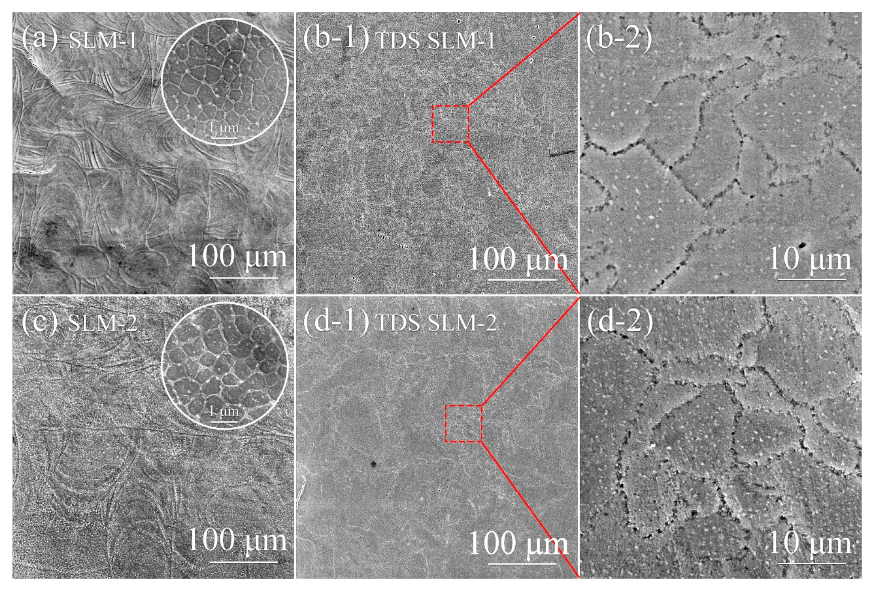
3.1. Defect Structure

A summary of the composition and microstructure of the samples is given in Table 1. The detailed microstructure of the SLM-built samples has been described in [10]. It comprises fine dislocation cells with some segregation of Mn and Ni alloying elements into the cell walls, and boundaries of grains and melt pools. The average size of the cell structure varied from 390 nm for SLM-1 to 520 nm for SLM-2, and the width of the cell walls was approximately ~40 nm (SLM-1) and ~80 nm (SLM-2).
Vacancy concentration in the samples was studied by applying positron annihilation measurements. The conventional S and W parameters obtained from the Doppler broadening spectrum are usually utilized to determine the microstructure evolution. The integration window for the S parameter describing the shape of the Doppler broadening annihilation line was set to |PL| < 0.4 a.u., which represents the relative annihilation fraction of positron with low momentum (valence) electron; the W parameter is defined with an integration window of 1.6 a.u. < |PL| < 4.0 a.u., which describes the positron annihilation fraction with a high momentum (core) electron. More details on the experimental techniques and data analysis can be found in [25].
Figure 1a shows the S-E curves in the SLM and PECS CrFeNiMn samples. The mean penetration depth values of energetic positrons are shown on the top X-axis suggesting the average detection depth profile of mono-energy slow positrons [28]. Here, the S parameter determined in 1173 K annealed pure Ni, which could be defined as a reference value of positron annihilation in defect-free solid, is also present in the figure by the dashed line. The variation of the S parameter determined in different samples indicates the difference in vacancy concentration. The S parameters determined in the alloy samples are always larger than in pure Ni, demonstrating that vacancy defects are detected in the SLM and PECS samples; higher S parameters are detected in SLM-built samples than in the PECS sample indicates the existence of more vacancy defects in SLM samples. The difference in vacancy information in different alloy samples could be attributed to the cooling rate during the alloy synthesis process. The higher cooling rate results in more vacancies in the solid because the annealing out of thermal vacancies in the samples is less effective during the fast cooling rate [29]. Thus, the higher cooling rate contributes to the higher S parameters observed in the SLM samples. Figure 1b shows the S-W plots in different alloy samples. The (S, W) data from one sample are easily fitted in one straight line, which indicates that only one type of vacancy defect was detected from the surface to the bulk. All of the (S, W) data are roughly distributed on the dashed line, implying that vacancy defects with similar structures (size) are detected in different samples.

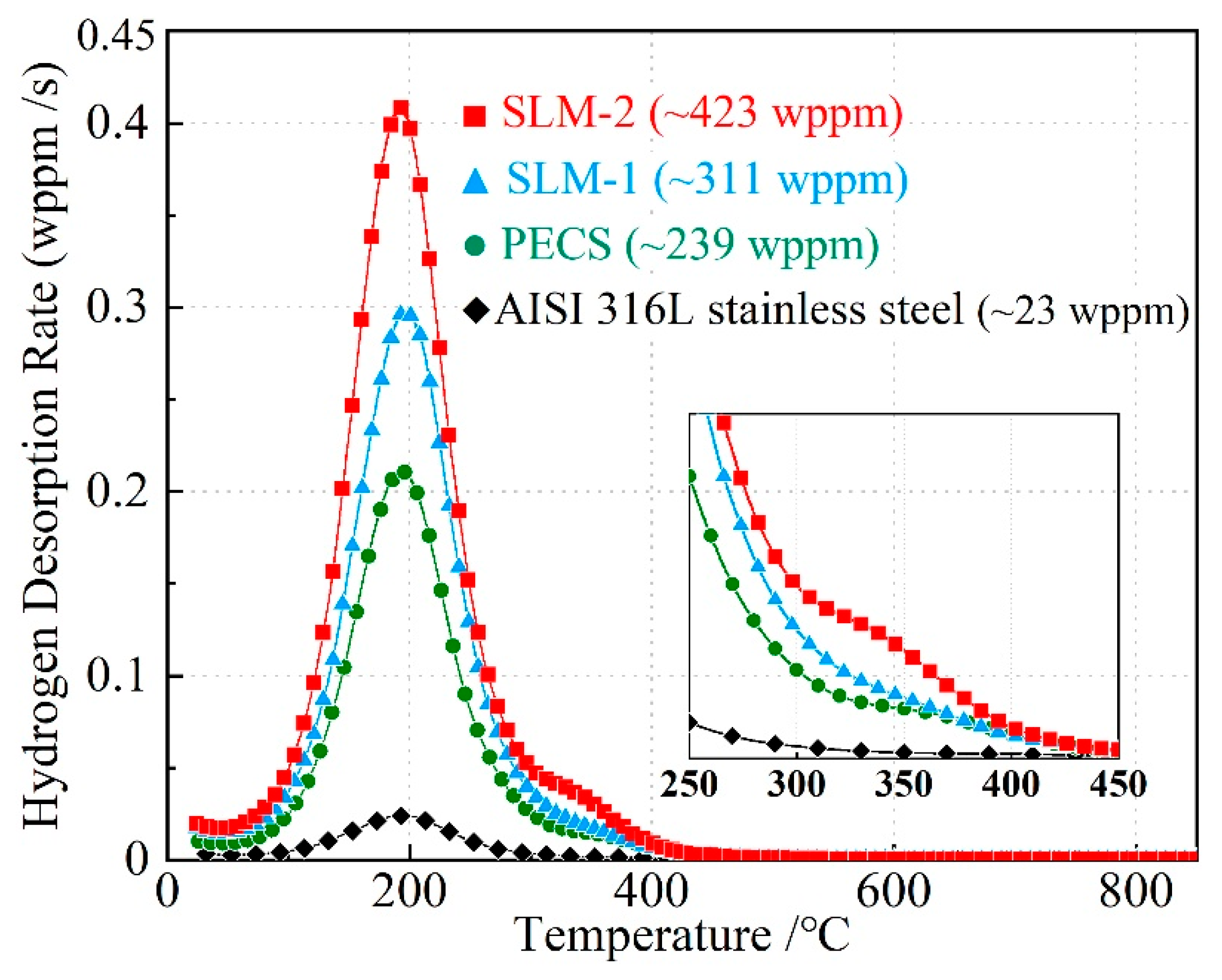
3.2. Hydrogen Uptake Ability

Figure 2 presents the variations of hydrogen desorption rate with the evaluated temperature of hydrogen-charged SLM and PECS CrFeNiMn specimens and the reference AISI 316L stainless steel. The first peak of each TDS curve is located close to 200 °C, where the desorption rate reaches the maximum. SLM-2 peaks the highest among the four curves at 0.41 wppm/s, SLM-1 achieves a slightly lower desorption rate peak value at 0.30 wppm/s, and PECS sample is even lower with a value at 0.21 wppm/s, while 316L steel shows the maximum only at 0.02 wppm/s. Both SLM specimens have a second peak located at around 337 °C, and the second peak of SLM-2 is higher than that of SLM-1. The average hydrogen concentration can be determined from the area under the TDS curve. It is found that hydrogen absorbed by SLM-1, SLM-2, PECS, and 316L steel samples was 311, 423, 239, and 23 wppm, respectively.
The distinct peaks in TDS curves reveal the different hydrogen binding energy in the trapping sites, and a higher temperature is required to release the hydrogen from the trapping sites, which possess higher binding energy. The lower temperature peaks presented in Figure 2 result from the release of hydrogen in relatively weak lattice trapping sites, such as interstitial sites and dislocations [30]. The TDS peaks of the SLM and PECS-processed CrFeNiMn-samples around 200 °C indicate a larger hydrogen concentration than in the 316L steel sample. This appears to be related to weak lattice trap sites in all CrFeNiMn samples and dislocation boundaries in the SLM-processed samples.
The higher temperature peaks are generally related to hydrogen release from defects requiring higher activation energy. Such defects are typically vacancies [24]. As the porosity of each specimen is similar and no blistering was observed, the main factors influencing the average hydrogen concentration are thus the lattice interstitial sites, and the lattice defects such as vacancies and dislocations. Nevertheless, vacancies are not expected to play a large role in absorbing hydrogen, as SLM-1 is identified to have a higher vacancy concentration than SLM-2, resulting from a faster cooling rate during processing (see in Figure 1a); however, the hydrogen concentration appears to be lower. As a note, some of the hydrogen detected at 350 °C may result from the hydrogen diffusing across the specimen thickness to the opposite side, especially in samples where the solubility and diffusivity of hydrogen are increased.
Hydrogen solubility in metals depends on both crystal structure and alloying elements. For instance, the solubility of hydrogen in the FCC structure is higher than that in the BCC structure, which results from the occupancy of hydrogen in the lattice structures [31]. It has been reported that the cast CoCrFeMnNi HEA has a higher H solubility than other FCC alloys due to the high chromium and manganese contents, which help improve the H solubility [32]. In addition, the high lattice strain energy and short-range order in multicomponent alloys may also contribute [21,33,34], as high H solubility has been observed in SLM CrMnFeCoNi alloy as well [21]. This was attributed to the influence of the nanoscale heterogeneity, e.g., short-range ordering on hydrogen trapping sites. These agree with our observation as CrFeNiMn specimens produced by SLM and PECS absorb more hydrogen than conventional 316L steel. On the other hand, Iacoviello et al. [34] investigated the hydrogen-induced fatigue crack propagation micromechanisms in several sintered steels, and they found that the damage level was higher with the increasing austenite/ferrite volume fraction, as austenitic grains acted as hydrogen traps and out-gassing sites. Despite so, it has been reported that in the 316L steel produced by powder metallurgy, e.g., by hot isostatic pressing (HIP), the finer grain size and larger grain boundary area were beneficial for the trapping of hydrogen. More hydrogen was absorbed, yet less susceptibility for cracking was shown [35]. The fact that SLM-processed specimens absorb more hydrogen than PECS-processed specimens suggests that the microstructure induced by SLM contributes to the enhancement of hydrogen uptake ability. A typical rapidly solidified microstructure produced by the SLM process is presented in a scanning transmission electron microscope (STEM) image in Figure 3. It consists of dislocation networks at the cell walls and to a lesser extent within the cells. A recent work by Lin et al. [36] showed that in comparison to the cold-rolled 316L SS, the H diffusion rate in the SLM-built 316L SS was much higher. They concluded that the hydrogen would diffuse initially along the cell walls then into the interior of cells, and the abundant cell walls in the SLM 316L SS act as rapid transportation paths for the H atoms; therefore, it suggests that the higher average hydrogen concentrations in SLM specimens are attributed to the high contents of chromium and manganese, and the cellular structure in conjunction with the elemental segregation and the high density of dislocations in the cell walls. Particularly, the larger average hydrogen concentration in SLM-2 compared to that in SLM-1 is ascribed to the broader cell walls associated with more severe segregation into the cell walls, as revealed in our previous study [10].
In a recent paper, Park et al. [37] compared the hydrogen effects in conventional AISI 316L steel and SLM-processed 316L steel, and noticed that the SLM-built 316L steel has less H content and a lower apparent H diffusivity in comparison to the conventionally manufactured alloy. Additionally, they claimed that the cell walls, which consisted of a high density of dislocations and segregated elements similar to our observations, were comparatively insensitive to H charging compared to cell interiors. This is apparently in conflict with the results of both Lin et al. [24] and ours, which reveal that the increase in dislocation density notably influences the hydrogen content of the material. Previous studies on the hydrogen absorption and diffusivity by Macadre et al. [38] have shown that the greater dislocation densities contribute to a higher hydrogen content and increase in hydrogen solubility, while the impact of dislocations on the hydrogen diffusivity is negligible. This was attributed to the large difference in energies for lattice diffusion and dislocation trapping, and to the relatively little hydrogen content trapped at dislocations in the FCC steels. The rationale for the variation in the results between us and those presented by Park et al. [37] may thus be their considerably smaller hydrogen content, which is more than ten times lower than in our charging experiments. Interestingly, the hydrogen uptake into the CrFeNiMn-equiatomic alloy was significantly higher (by more than an order of magnitude) than into the common stainless steel 316L. It indicates that the hydrogen diffusivity is increased in the CrFeNiMn-equiatomic alloy compared to conventional alloys.

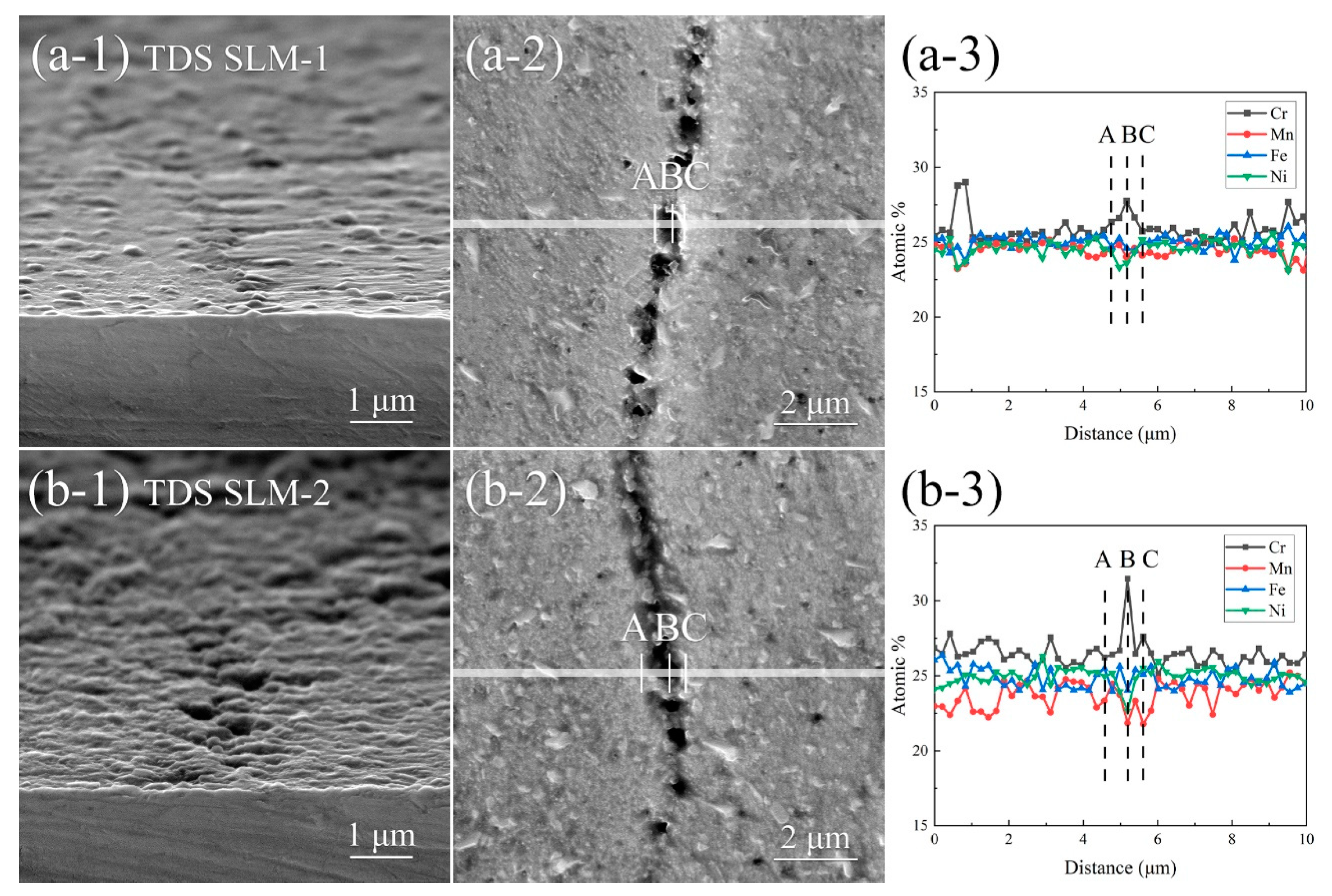
3.3. Analysis of TDS-Tested Specimens

Both as-built SLM specimens consist of a single FCC phase [10]; after the TDS test, small BCC peaks are detected in Figure 4. Peaks resulting from the BCC phase are considerably reduced once polishing 150 μm off the surface, but there remains a small BCC phase in polished TDS-tested specimens. Moreover, the compositions given in Table 1 show that the surface of the specimens experiences a small loss of Mn in the TDS test. In TDS-tested SLM-1, the surface content of Mn declines from 24.9 to 24.7 at%, TDS-tested SLM-2 suffers a larger loss from 24.0 to 23.4 at%, and TDS-tested PECS also loses Mn from 24.2 to 23.6 at%. After polishing off around 150 μm from the surface, Mn content returns to the as-built composition.
The secondary electron (SE) images in Figure 5a,c reveal the typical melt pool boundaries and magnified cellular structures of the electrochemically etched top surface of SLM CrFeNiMn specimens. Figure 5c displays the broader cell walls of SLM-2 than that of SLM-1 in Figure 5c, which contributes to absorbing more hydrogen, as discussed above. After the TDS test, tracks of pits are formed on the surface of both specimens along grain boundaries, as shown in Figure 5b,d. Further observation on the xz-plane in Figure 6(a-1,b-1) confirms that the pits have a width and depth in the submicron scale. TDS-tested SLM-1 displays less rough and uneven surface morphology, and narrower and shallower pits are found compared to the TDS-tested SLM-2. The EDS line scan results taken from Figure 6(a-2,b-2) in Figure 6(a-3,b-3) display that for both TDS-tested specimens, the content of Cr varies along with that of Fe, whereas Mn and Ni show the same variation trend, and this is due to the segregation of Mn and Ni in the boundaries of cells, grains, and melt pools. In TDS-tested SLM-1, the content of Fe and Ni keeps relatively stable at around 25 at%, whereas in the TDS-tested SLM-2, the fluctuation of all the lines of alloying elements varies more significantly. Particularly, the fluctuation of Mn content in TDS-tested SLM-2 is from 21.9 to 25.2 at%, whereas before TDS, it was from 22.9% to 25.3%. As a consequence of Mn loss, the atomic percentage of other elements rises correspondingly.
The BCC phase formation is likely related to the loss of manganese, which reduces the stability of the FCC phase, or to the hydrogen-induced transformation of austenite. On the other hand, hydrogen charging is known to induce martensite transformation in relatively stable austenitic stainless steels due to the high stresses induced by the deep hydrogen gradient in the sample’s surface [39]. It can also raise the martensitic start temperature (Ms) and the highest temperature for deformation-induced martensite transformation [40]. Previously, the additively manufactured austenite phase has been observed to be more stable than that produced conventionally. Kong et al. [41] reported that in SLM 316L steel showed little martensite transformation after being electrochemically charged for 4 h at a current density of 50 mA/cm2, and this stability of the austenitic phase benefited from the microstructure produced by SLM, such as the cellular structure and high density of dislocations. The mutual influence of intrinsic effects of hydrogen and high stresses due to the hydrogen concentration gradient at the sample surface is still under debate and needs further investigations.

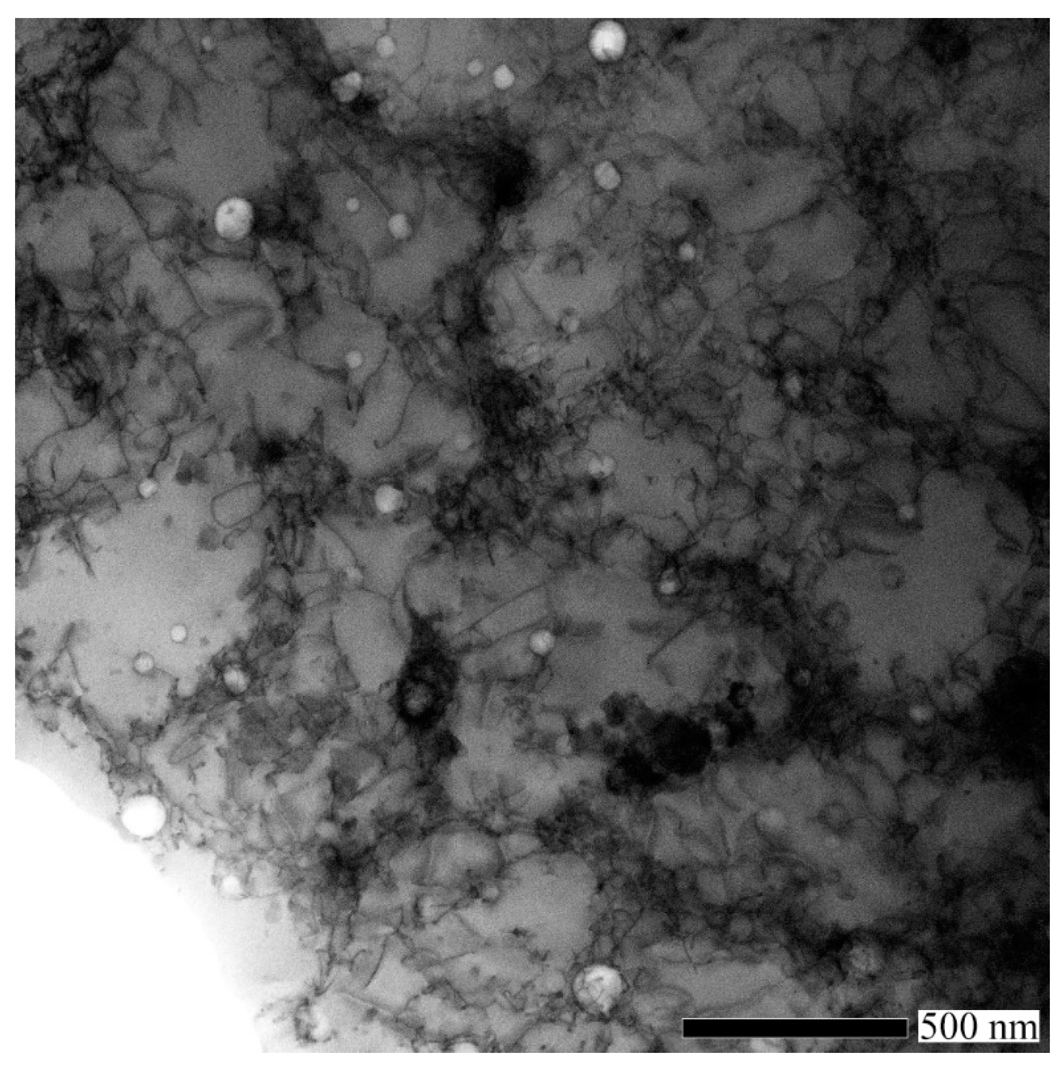
3.4. Analysis of TEM Specimen

The typical bright-field (BF) TEM image of the SLM-2 CrFeNiMn specimen is shown in Figure 7a. The image displays a single FCC phase structure with some small inclusions and dislocations. In the bright-field scanning transmission electron microscopy (BF-STEM) image (see in Figure 7b) taken after 3 h aging of the HC sample, some stacking faults are also observed (magnified in Figure 7e). This indicates that the stacking fault energy (SFE) of SLM CrFeNiMn alloy is decreased due to hydrogen. The same feature is also found in conventional austenitic stainless steels [42], which are regarded as examples of non-hydride forming materials where hydrogen-induced cracking and hydrogen-related failure sequences occur via stress gradients and/or phase transformations depending on the austenite stability [43]. Metastable austenitic stainless steels undergo surface cracking associated with the formation of α’- and ε-martensites during cathodic charging [44]. Simultaneously, hydrogen-induced FCC- and HCP-phases are observed [45,46]. Transformations are related to the steep hydrogen gradient and related steep stress gradients. In high-alloyed stable austenitic stainless steels, only expanded FCC phases and related deformation are observed [40].
After 3 h of aging, some cracks along the planar faults are observed in the thin TEM sample, as circled with the green dotted lines shown in Figure 7b. Observation of the same area after 24 h aging shows that part of the specimen has separated from the specimen along the cracks, as circled with the green dotted line and marked with the green arrow in Figure 7c. The direction of cracks suggests that they may have initiated from stacking faults. Cracking has earlier been observed to associate with planar faults on (111)-planes in austenitic stainless steels [47]. The dark-field images (example in Figure 7e) revealed stacking faults associated with the strain field. A ring pattern with FCC structure from nanocrystals inside one matrix grain is shown in Figure 7d. The overlap of the spot pattern from matrix and ring pattern indicates that the lattice parameter of nanocrystals is very close to the matrix lattice parameter. The nanocrystals are mostly located along dislocation lines. These appear to have formed due to the hydrogen-induced volume-change-related deformation. The volume increment associated with the addition of four hydrogen atoms to the octahedral sites in the FCC unit cell is 11.5 Å3 [48]. Hydrogen gradients may thus induce large stresses in the charged sample. Furthermore, calculations show that even a weakly attractive interaction between interstitial H atoms in the matrix dramatically increases the local H concentration in the tensile strain field of the dislocation, resulting in the formation of a local hydride phase along the dislocation line [49].
The distribution of hydrogen in the sample may also vary, e.g., in areas where chromium or nickel are segregated [50]. TEM-EDS maps taken from Figure 7c in Figure 7f and micrographs in Figure 6(a-2,b-2) also exhibit cracks following the boundaries of grains and cell walls. When hydrogen is introduced into the SLM specimen, it is expected to diffuse into the walls of cellular structure at first, and microcracks are likely to initiate along the edges of Mn-enriched and Cr-Mn-enriched nano inclusions [10] embedded in the specimen, and they may tend to fall off.

4. Conclusions

Effects of SLM on the hydrogen uptake of the single-phase FCC CrFeNiMn alloy after cathodic hydrogen charging was studied. Samples produced by the SLM process contained an increasing number of dislocations and vacancies with increasing energy density, while the PECS sample and 316L steel sample were in the annealed state. It is found that the amount of hydrogen absorbed by SLM-1, SLM-2, PECS, and 316L steel samples was 311, 423, 239, and 23 wppm, respectively. The amount of hydrogen in SLM-2 (produced under the higher laser energy density) was approximately 20 times higher than that in 316L steel. The higher hydrogen uptake of CrFeNiMn alloys in comparison to 316L seems to be associated with the equiatomic structure. The SLM-induced microstructure consisting of cellular structure in combination with dislocations and segregation results in increased hydrogen uptake compared to the PECS-processed sample. This difference appears to be related to the dislocation and vacancy densities of samples, and that of sample SLM-2 and SLM-1 to the width of the cell wall area and alloying element segregation of the sample. Hydrogen-charged TEM and the aged specimen revealed austenite with stacking faults and cracks along the (111)-planes of austenite. Hydrogen-induced cracks and submicron pits at the grain boundary inclusions were confirmed by SEM.

Author Contributions

Conceptualization, S.-P.H.; methodology, Y.G. and X.Y.; formal analysis, Y.Y., Y.G., E.L. and X.Y.; investigation, Y.Y., Y.G., E.L., X.Y. and J.L.; resources, L.K.; data curation, Y.Y., Y.G., E.L. and X.Y.; writing—original draft preparation, E.L. and X.Y.; writing—review and editing, S.-P.H., Y.G., E.L. and Y.Y.; visualization, X.Y.; supervision, S.-P.H. All authors have read and agreed to the published version of the manuscript.

Funding

This research was funded by the Foundation for Aalto University Science and Technology and the China Scholarship Council fellowship (grant number 201706040062).

Acknowledgments

The authors would like to thank Outokumpu Oyj for donating raw materials, and Ing. Volker Uhlenwinkel from the University of Bremen for performing the gas atomization of powder. The experimental equipment was used by the Aalto University RawMatters Facilities and OtaNano Nanomicroscopy Center.

Conflicts of Interest

The authors declare no conflict of interest. The funders had no role in the design of the study; in the collection, analyses, or interpretation of data; in the writing of the manuscript, or in the decision to publish the results.

References

  1. George, E.P.; Raabe, D.; Ritchie, R.O. High-entropy alloys. Nat. Rev. Mater. 2019, 4, 515–534. [Google Scholar] [CrossRef]
  2. Okamoto, N.L.; Fujimoto, S.; Kambara, Y.; Kawamura, M.; Chen, Z.M.T.; Matsunoshita, H.; Tanaka, K.; Inui, H.; George, E.P. Size effect, critical resolved shear stress, stacking fault energy, and solid solution strengthening in the CrMnFeCoNi high-entropy alloy. Sci. Rep. 2016, 6, 35863. [Google Scholar] [CrossRef]
  3. Tasan, C.C.; Deng, Y.; Pradeep, K.G.; Yao, M.J.; Springer, H.; Raabe, D. Composition dependence of phase stability, deformation mechanisms, and mechanical properties of the CoCrFeMnNi High-entropy alloy system. JOM 2014, 66, 1993–2001. [Google Scholar] [CrossRef]
  4. Wu, H. Excellent mechanical properties of in-situ TiC/FeCrNiCuV0.1 high entropy alloy matrix composites. Mater. Lett. 2019, 4, 257. [Google Scholar] [CrossRef]
  5. Lu, C.; Niu, L.; Chen, N.; Jin, K.; Yang, T.; Xiu, P.; Zhang, Y.; Gao, F.; Bei, H.; Shi, S.; et al. Enhancing radiation tolerance by controlling defect mobility and migration pathways in multicomponent single-phase alloys. Nat. Commun. 2016, 7, 13564. [Google Scholar] [CrossRef] [PubMed]
  6. Wu, Z.; Bei, H. Microstructures and mechanical properties of compositionally complex Co-free FeNiMnCr18 FCC solid solution alloy. Mater. Sci. Eng. A 2015, 640, 217–224. [Google Scholar] [CrossRef] [Green Version]
  7. Kumar, N.A.P.K.; Li, C.; Leonard, K.J.; Bei, H.; Zinkle, S.J. Microstructural stability and mechanical behavior of FeNiMnCr high entropy alloy under ion irradiation. Acta Mater. 2016, 113, 230–244. [Google Scholar] [CrossRef] [Green Version]
  8. Eißmann, N.; Klöden, B.; Weißgärber, T.; Kieback, B. High-entropy alloy CoCrFeMnNi produced by powder metallurgy. Powder Metall. 2017, 60, 184–197. [Google Scholar] [CrossRef]
  9. Liu, L.; Ding, Q.; Zhong, Y.; Zou, J.; Wu, J.; Chiu, Y.-L.; Li, J.; Zhang, Z.; Yu, Q.; Shen, Z. Dislocation network in additive manufactured steel breaks strength–ductility trade-off. Mater. Today 2018, 21, 354–361. [Google Scholar] [CrossRef] [Green Version]
  10. Yang, X.; Ge, Y.; Lehtonen, J.; Hannula, S.-P. Hierarchical microstructure of laser powder bed fusion produced face-centered-cubic-structured equiatomic CrFeNiMn multicomponent alloy. Materials 2020, 13, 4498. [Google Scholar] [CrossRef]
  11. Donik, Č.; Kraner, J.; Paulin, I.; Godec, M. Influence of the energy density for selective laser melting on the microstructure and mechanical properties of stainless steel. Metals 2020, 10, 919. [Google Scholar] [CrossRef]
  12. Konovalov, S.; Osintsev, K.; Golubeva, A.; Smelov, V.; Ivanov, Y.; Chen, X.; Komissarova, I. Surface modification of Ti-based alloy by selective laser melting of Ni-based superalloy powder. J. Mater. Res. Technol. 2020, 9, 8796–8807. [Google Scholar] [CrossRef]
  13. Do, D.K.; Li, P. The Effect of laser energy input on the microstructure, physical and mechanical properties of Ti-6Al-4V alloys by selective laser melting. Virtual Phys. Prototyp. 2016, 11, 41–47. [Google Scholar] [CrossRef]
  14. Chang, K.-C.; Zhao, J.-R.; Hung, F.-Y. Microstructure, mechanical properties, and fatigue fracture characteristics of high-fracture-resistance selective laser melting Al-Ni-Cu alloys. Metals 2021, 11, 87. [Google Scholar] [CrossRef]
  15. Brif, Y.; Thomas, M.; Todd, I. The use of high-entropy alloys in additive manufacturing. Scr. Mater. 2015, 99, 93–96. [Google Scholar] [CrossRef]
  16. Saeidi, K.; Gao, X.; Zhong, Y.; Shen, Z.J. Hardened austenite steel with columnar sub-grain structure formed by laser melting. Mater. Sci. Eng. A 2015, 625, 221–229. [Google Scholar] [CrossRef]
  17. Turnbull, A.; Hutchings, R.B.; Ferriss, D.H. Modelling of thermal desorption of hydrogen from metals. Mater. Sci. Eng. A 1997, 238, 317–328. [Google Scholar] [CrossRef]
  18. Yagodzinskyy, Y.; Saukkonen, T.; Kilpeläinen, S.; Tuomisto, F.; Hänninen, H. Effect of hydrogen on plastic strain localization in single crystals of austenitic stainless steel. Scr. Mater. 2010, 62, 155–158. [Google Scholar] [CrossRef]
  19. Luo, H.; Li, Z.; Raabe, D. Hydrogen enhances strength and ductility of an equiatomic high-entropy alloy. Sci. Rep. 2017, 7. [Google Scholar] [CrossRef] [PubMed] [Green Version]
  20. Nygren, K.E.; Bertsch, K.M.; Wang, S.; Bei, H.; Nagao, A.; Robertson, I.M. Hydrogen embrittlement in compositionally complex FeNiCoCrMn FCC solid solution alloy. Curr. Opin. Solid State Mater. Sci. 2017. [Google Scholar] [CrossRef]
  21. Kim, Y.-K.; Suh, J.-Y.; Lee, K.-A. Effect of gaseous hydrogen embrittlement on the mechanical properties of additively manufactured CrMnFeCoNi high-entropy alloy strengthened by in-situ formed oxide. Mater. Sci. Eng. A 2020, 796, 140039. [Google Scholar] [CrossRef]
  22. Lee, D.-H.; Sun, B.; Lee, S.; Ponge, D.; Jägle, E.A.; Raabe, D. Comparative study of hydrogen embrittlement resistance between additively and conventionally manufactured 304L austenitic stainless steels. Mater. Sci. Eng. A 2021, 803, 140499. [Google Scholar] [CrossRef]
  23. Silverstein, R.; Eliezer, D. Mechanisms of hydrogen trapping in austenitic, duplex, and super martensitic stainless steels. J. Alloys Compd. 2017, 720, 451–459. [Google Scholar] [CrossRef]
  24. Fukai, Y.; Mizutani, M.; Yokota, S.; Kanazawa, M.; Miura, Y.; Watanabe, T. Superabundant vacancy–hydrogen clusters in electrodeposited Ni and Cu. J. Alloys Compd. 2003, 4, 270–273. [Google Scholar] [CrossRef]
  25. Tuomisto, F.; Makkonen, I. Defect identification in semiconductors with positron annihilation: Experiment and theory. Rev. Mod. Phys. 2013, 85, 1583–1631. [Google Scholar] [CrossRef] [Green Version]
  26. Lu, E.; Makkonen, I.; Mizohata, K.; Li, Z.; Räisänen, J.; Tuomisto, F. Effect of interstitial carbon on the evolution of early-stage irradiation damage in equi-atomic FeMnNiCoCr high-entropy alloys. Appl. Phys. 2020, 8. [Google Scholar] [CrossRef]
  27. Lehtonen, J.; Ge, Y.; Ciftci, N.; Heczko, O.; Uhlenwinkel, V.; Hannula, S.-P. Phase structures of gas atomized equiatomic CrFeNiMn high entropy alloy powder. J. Alloys Compd. 2020, 827, 154142. [Google Scholar] [CrossRef]
  28. Lu, E.; Cao, X.; Jin, S.; Zhang, P.; Zhang, C.; Yang, J.; Wu, Y.; Guo, L.; Wang, B. Investigation of vacancy-type defects in helium irradiated FeCrNi alloy by slow positron beam. J. Nucl. Mater. 2015, 458, 240–244. [Google Scholar] [CrossRef]
  29. Morris, M.A.; George, O.; Morris, D.G. Vacancies, vacancy aggregates and hardening in FeAl. Mater. Sci. Eng. A 1998, 258, 99–107. [Google Scholar] [CrossRef]
  30. Ryu, J.H.; Chun, Y.S.; Lee, C.S.; Bhadeshia, H.K.D.H.; Suh, D.W. Effect of deformation on hydrogen trapping and effusion in TRIP-assisted steel. Acta Mater. 2012, 60, 4085–4092. [Google Scholar] [CrossRef]
  31. Kirchheim, R.; Pundt, A. Hydrogen in metals. In Physical Metallurgy; Elsevier: Amsterdam, The Netherlands, 2014; pp. 2597–2705. ISBN 978-0-444-53770-6. [Google Scholar]
  32. Zhao, Y.; Lee, D.-H.; Seok, M.-Y.; Lee, J.-A.; Phaniraj, M.P.; Suh, J.-Y.; Ha, H.-Y.; Kim, J.-Y.; Ramamurty, U.; Jang, J. Resistance of CoCrFeMnNi high-entropy alloy to gaseous hydrogen embrittlement. Scr. Mater. 2017, 135, 54–58. [Google Scholar] [CrossRef]
  33. Gao, M.C.; Yeh, J.-W.; Liaw, P.K.; Zhang, Y. (Eds.) High-Entropy Alloys; Springer International Publishing: Cham, Switzerland, 2016; ISBN 978-3-319-27011-1. [Google Scholar]
  34. Zhao, Y.; Park, J.-M.; Lee, D.-H.; Song, E.J.; Suh, J.-Y.; Ramamurty, U.; Jang, J. Influences of hydrogen charging method on the hydrogen distribution and nanomechanical properties of face-centered cubic high-entropy alloy: A comparative study. Scr. Mater. 2019, 168, 76–80. [Google Scholar] [CrossRef]
  35. Baek, S.-W.; Song, E.J.; Kim, J.H.; Lee, Y.-H.; Ryu, K.S.; Kim, S.-W. Hydrogen susceptibility of nano-sized oxide dispersed austenitic steel for fusion reactor. Fusion Eng. Des. 2017, 121, 105–110. [Google Scholar] [CrossRef]
  36. Lin, J.; Chen, F.; Liu, F.; Xu, D.; Gao, J.; Tang, X. Hydrogen permeation behavior and hydrogen-induced defects in 316L stainless steels manufactured by additive manufacturing. Mater. Chem. Phys. 2020, 250, 123038. [Google Scholar] [CrossRef]
  37. Park, J.-M.; Zhao, Y.; Voisin, T.; Lee, D.-H.; Komazaki, S.; Ko, Y.; Kim, D.-I.; Suh, J.-Y.; Han, H.N.; Wang, Y.M.; et al. Hydrogen uptake and its influence in selective laser melted austenitic stainless steel: A nanoindentation study. Scr. Mater. 2021, 194, 113718. [Google Scholar] [CrossRef]
  38. Macadre, A.; Masumura, T.; Manabe, R.; Tsuchiyama, T.; Takaki, S. Effect of nitrogen-addition on the absorption and diffusivity of hydrogen in a stable austenitic stainless steel. Int. J. Hydrogen Energy 2019, 44, 1263–1271. [Google Scholar] [CrossRef]
  39. Hoelzel, M.; Rajevac, V.; Danilkin, S.A.; Udovic, T.J.; Wipf, H.; Fuess, H. Lattice dynamics of high-pressure hydrogenated austenitic stainless steels. J. Phys. Condens. Matter 2005, 17, 3537–3546. [Google Scholar] [CrossRef]
  40. Narita, N.; Altstetter, C.J.; Birnbaum, H.K. Hydrogen-related phase transformations in austenitic stainless steels. Metall. Trans. A 1982, 13, 1355–1365. [Google Scholar] [CrossRef]
  41. Kong, D.; Dong, C.; Ni, X.; Zhang, L.; Luo, H.; Li, R.; Wang, L.; Man, C.; Li, X. Superior resistance to hydrogen damage for selective laser melted 316L stainless steel in a proton exchange membrane fuel cell environment. Corros. Sci. 2020, 166, 108425. [Google Scholar] [CrossRef]
  42. Whiteman, M.B.; Troiano, A.R. the influence of hydrogen on the stacking fault energy of an austenitic stainless steel. Phys. Status Solid. B 1964, 7, K109–K110. [Google Scholar] [CrossRef]
  43. Eliezer, D.; Chakrapani, D.G.; Altstetter, C.J.; Pugh, E.N. The influence of austenite stability on the hydrogen embrittlement and stress- corrosion cracking of stainless steel. Metall. Trans. A 1979, 10, 935–941. [Google Scholar] [CrossRef]
  44. Rozenak, P.; Eliezer, D. Phase changes related to hydrogen-induced cracking in austenitic stainless steel. Acta Metall. 1987, 35, 2329–2340. [Google Scholar] [CrossRef]
  45. Zevin, L.S.; Rozenak, P.; Eliezer, D. Quantitative X-ray phase analysis of surface layers. J. Appl. Crystallogr. 1984, 17, 18–21. [Google Scholar] [CrossRef]
  46. Eliezer, D.; Tal-Gutelmacher, E.; Boellinghaus, T. Hydrogen Embrittlement in Hydride- and Non Hydride-Forming Systens–Microstructural/Phase Changes and Cracking Mechanisms. In Proceedings of the 11th International Conference on Fracture, Turin, Italy, 20–25 March 2005; Available online: http://www.gruppofrattura.it/ocs/index.php/ICF/ICF11/paper/view/10870/10199 (accessed on 19 March 2016).
  47. Hannula, S.-P. The effect of pre-existing epsilonmartensite on the hydrogen induced fracture of austenitic stainless steel. Scr. Metall. 1983, 17, 509–513. [Google Scholar] [CrossRef]
  48. Baranowskip, B.; Flanagans, T.B. The volume increase of Fcc metals and alloys due to interstitial hydrogen over a wide range of hydrogen contents. J. Phys. F Met. Phys. 1971, 1, 5. [Google Scholar]
  49. von Pezold, J.; Lymperakis, L.; Neugebeauer, J. Hydrogen-enhanced local plasticity at dilute bulk H concentrations: The role of H–H interactions and the formation of local hydrides. Acta Mater. 2011, 59, 2969–2980. [Google Scholar] [CrossRef]
  50. Mine, Y.; Kimoto, T. Hydrogen uptake in austenitic stainless steels by exposure to gaseous hydrogen and its effect on tensile deformation. Corros. Sci. 2011, 53, 2619–2629. [Google Scholar] [CrossRef]
Figure 1. Positron annihilation Doppler broadening data of SLM CrFeNiMn specimens and reference materials. (a) Variation of S parameter as the function of incident positron energy. (b) W parameter as the function of S parameter. Error bars are smaller than the markers.
Metals 11 00872 g001
Figure 2. TDS spectrum of SLM CrFeNiMn specimens and reference materials.
Metals 11 00872 g002
Figure 3. STEM micrograph on dislocation cells of the as-built SLM-2 CrFeNiMn alloy.
Metals 11 00872 g003
Figure 4. XRD patterns of TDS-tested SLM CrFeNiMn alloy with non-polished and polished specimens.
Metals 11 00872 g004
Figure 5. SE micrographs on the xy-plane of as-built and TDS-tested SLM CrFeNiMn alloy. (a,b) SLM-1 and (c,d) SLM-2. The micrographs in (b-2) and (d-2) are the magnified square areas in (b-1) and (d-1), respectively.
Metals 11 00872 g005
Figure 6. High-magnification SE images on the xz-plane, BSE images on the xy-plane of the SLM CrFeNiMn alloy, and corresponding composition profiles. (a) TDS-tested SLM-1 and (b) TDS-tested SLM-2.
Metals 11 00872 g006
Figure 7. TEM observation on as-built and hydrogen-charged SLM-2 CrFeNiMn alloy. (a) Representative BF TEM image on xy-plane with SAD. (b) BF-STEM image of hydrogen charged specimen after 3 h of aging. (c) BF STEM image of hydrogen charged specimen after 24 h of aging. (d) SAD pattern and ring pattern. (e) DF TEM image of magnified circle area in (b) showing the presence of planar defects, most likely overlapping stacking faults. (f) Corresponding quantitative EDS maps of (c).
Metals 11 00872 g007
Table 1. Porosity and chemical compositions (in at%) of SLM and PECS CrFeNiMn alloy.
SampleCrMnFeNiPorosityAverage Cell Size (nm)
SLM-125.524.924.824.82.0390
TDS SLM-125.724.725.024.6--
TDS SLM-1 Polished25.125.025.224.7--
SLM-225.824.025.324.92.1520
TDS SLM-226.123.425.525.0--
TDS SLM-2 Polished25.323.925.625.2--
PECS26.024.225.324.52.4-
TDS PECS26.423.625.025.0--
Publisher’s Note: MDPI stays neutral with regard to jurisdictional claims in published maps and institutional affiliations.

