Abstract
Ultrasonic nanocrystal surface modification (UNSM) technology was applied to the surfaces of specimens additively manufactured by powder bed fusion (PBF). The changes in roughness and hardness due to the UNSM were set as objective functions, and the optimal conditions for the main parameters were derived through the response surface method (RSM) and Box–Behnken design (BBD). Regression analysis-based mathematical models for predicting the surface hardness and roughness are presented and validated. The RSM results show that the surface roughness is highly dependent on the load and ball tip diameter, and the surface roughness significantly improves as the inter-pass interval and ball tip diameter decrease. Through BBD and ANOVA, the optimal conditions for the improvement of surface characteristics were found to be a load of 40 N, inter-pass interval of 10 μm, and ball tip diameter of 2.38 m. The surface treated under these optimal conditions exhibited a hardness of 497 Hv and surface roughness of 1.32 μm, which were significantly improved compared to the values for an untreated specimen. In addition, it was confirmed that the grains are significantly refined after UNSM, and scratch resistance increases for the top layer of the surface directly affected by the UNSM horn.
1. Introduction
Additive manufacturing (AM) is the construction of a three-dimensional object from a CAD model or a digital 3D model [1]. AM has been used in the manufacturing, medical, industry and sociocultural sectors which facilitate AM becoming a successful commercial technology. An AM system may be classified/categorized in terms of the material feed stock, energy source, build volume, etc. Across many sectors, metal additive manufacturing is providing an effective alternative to existing processes, allowing additive manufacturing companies to create cost-effective productions even at low volumes as well as shorten lead times, reduce part count and offer many more advantages [2].
However, its wide application is limited by some inherent disadvantages, such as poor surface finish and high porosity. Therefore, surfaces manufactured by metal AM technology are subjected to post-processes. There are various post-processing methods: physical methods, such as mechanical polishing and sand blasting; chemical methods, such as etching and electropolishing; and thermodynamic processes for treating the surface with radiating plasma. However, such post-processes are subtractive, meaning the deposited material is removed. They do not improve the mechanical properties and only affect the surface roughness. In recent years, surface hardening studies have been conducted to improve the surfaces of metal components manufactured by AM. Surface hardening is a post-treatment process that increases hardness and wear resistance and maintains the toughness of the material. Surface hardening is mainly divided into chemical surface hardening, which changes the chemical composition, and physical surface hardening, which does not change the chemical composition. Chemical surface hardening includes nitriding, in which steel is heated in ammonia gas over an extended period of time to form a nitride layer [3], and carburizing, in which carbon penetrates the metal surface [4]. Physical surface hardening includes metal spraying, in which molten metals are attached to a surface by spraying them with compressed air [5]; induction hardening, in which a surface is hardened using high-frequency current and coolant injection [6]; and shot peening, in which the surface layer is hardened by injecting metals at high speed.
In shot peening, a type of cold working, 0.5–0.1 mm metal shot balls strike the metal surface through high-speed airflow. A thin, plastically deformed layer is formed on the surface through repeated impacts. In such a deformed layer, compressive residual stress is produced. Compressive residual stress extends the fatigue life by offsetting the tension under repeated tensile loads. Shot peening includes hot shot peening, which is performed near the austenite or martensite transformation temperature, and a water jet in which water is injected at a high speed for processing. Kim et al. applied shot peening to aluminum alloys and verified that compressive residual stress improved the fatigue life [7]. In addition, the surface and mechanical characteristics have been improved using shot peening in many studies [8,9]. However, shot peening has low precision because it is impossible to adjust the positions of the injected metal balls accurately. In addition, the shot balls used cause environmental pollution. Studies on peening to address these shortcomings have been conducted.
Laser shock peening is a method of hardening by transferring the energy of a high-power laser beam to the material surface in the form of heat and shock waves, and it can also produce a self-quenching effect. This technology generates structures with high hardness values and prevents thermal deformation and stress. Laser shock peening uses 30–300 μm laser spots, thereby enabling finer and more precise processing than shot peening [10]. Laser shock peening technology, however, requires a robot dedicated to laser beam irradiation, and thermal deformation of the material may occur owing to plasma exposure [11].
In this study, surface hardening using ultrasonic nanocrystal surface modification (UNSM) was investigated. UNSM is a technology that modifies a surface crystalline structure using ultrasonic vibration energy. It is more precise and eco-friendly than shot peening and more economical than laser shock peening. In addition, many studies have verified that UNSM technology improves the surface roughness, wear resistance, and fatigue strength of metal. Lee et al. confirmed the possibility of extending the service lives of press dies through wear tests [12]. Moreover, Cho et al. improved the surface characteristics of an aluminum alloy, AlSi10Mg, produced by direct metal laser sintering through the application of UNSM, and Kheradmandfard et al. utilized UNSM to improve the surface hardness of the titanium–niobium–tantalum–zirconium alloy [13,14]. Thus, many studies have been conducted to improve the surface and mechanical characteristics of various materials by applying UNSM technology [15,16,17]. Amanov et al. applied UNSM treatment to tool steel at 500 °C and confirmed an improvement in performance [18]. Pyun et al. analyzed the effects of the number and direction of UNSM treatment on the surface and mechanical characteristics of D2 and observed the surface changes between before and after heat treatment [19].
Owing to these benefits of UNSM, studies have been conducted on the surface treatment of additively manufactured materials using UNSM. Ye et al. proposed an innovative method, electrically-assisted ultrasonic nanocrystal surface modification (EA-UNSM), to process additively built Ti-6Al-4V samples. They investigated the effect of EA-UNSM on surface finish, microstructure, porosity and in-depth hardness [20]. Shim et al. investigated the changes in the metallurgical and mechanical properties induced by UNSM treatment in M4 built by directed energy deposition [21]. Cho et al. investigated the effects of ultrasonic nanocrystal surface modification (UNSM) treatment at room and high temperatures (RT and HT of 400 °C) on friction and wear behavior of Ti-6Al-4V alloy prepared by selective laser melting [22]. Amanov [23] tailored a Co–Cr–Mo alloy prepared by the AM method to contain both the gradient nanostructure and harmonic structure by UNSM at 25 and 500 °C, respectively. These previous studies reported that the wear and fatigue resistances of additively manufactured material surfaces were improved by UNSM treatment.
In most studies on UNSM treatment for additively manufactured materials, the rough surfaces were removed first through post-AM machining, and then surface treatment was applied. On the contrary, in this study, UNSM was applied to the deposited surface without post-processing as a surface treatment to improve the poor surface quality and mechanical performance of products created by PBF. In this study, the process conditions of UNSM for a PBF-deposited surface were varied to analyze their effects on surface roughness and hardness. The response surface methodology (RSM) and Box–Behnken design (BBD) were applied to derive process conditions that can most significantly improve surface roughness and hardness. In addition, regression analysis-based mathematical models for predicting the roughness and hardness after UNSM treatment are presented and compared with a specimen whose surface was processed through machining.
2. Materials and Methods
2.1. Materials
In this study, austenitic stainless steel (316 L) was used as a base metal material and metal powder. The base metal was manufactured using the PBF process. For the PBF process, 316 L spherical powder with sizes of 22–53 μm was used. Table 1 lists the chemical composition of the metal powder used in the experiment. Sodic’s (Sodic Co., Schaumburg, IL, USA) OPM250L commercial device was used in the PBF process. For deposition, a laser power of 370 W, feed rate of 800 mm/min, and laser diameter of 0.2 mm were used. In addition, heat treatment was performed upon completion of the deposition to remove the internal stress generated during the process, and then the fabricated base metal was removed from the build bed. The base metal was a rectangular parallelepiped with a width of 20 mm, depth of 10 mm, and height of 5 mm, and UNSM treatment was applied to a partial section of the deposited surface.

Table 1.
Chemical composition of material [wt%].
2.2. Ultrasonic Nanocrystal Surface Modification (UNSM)
UNSM induces severe plastic deformation on the material (or component) surface by causing tens of thousands of collisions per second with an amplitude of several μm using ultrasonic vibration energy. It can refine the microstructure of a material to a certain depth from its surface and create regular micro-dimples on the surface. The refined structure improves wear resistance and impact resistance by enhancing the hardness, compressive residual stress, and wear and fatigue characteristics.
Figure 1 shows a schematic diagram and the application of UNSM to the material surface. The static load is controlled with weights, and ultrasonic waves of a certain frequency are generated by the ultrasonic oscillator (refer to Figure 2). The generated ultrasonic waves are used when the transducer and booster devices deliver a load to an indenter, on which a ball tip of WC material (1700 HV) is attached. Here, the delivered load corresponds to the static load of the weights combined with the dynamic load resulting from the vibration energy of the ultrasonic waves. Because the UNSM device is installed on a numerical control/computer numerical control (NC/CNC) machine tool, precise processing of the surface is possible. It was produced by DesignMecha, Inc. and specifically installed on a CNC machining center.
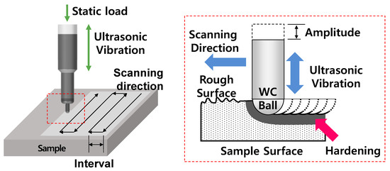
Figure 1.
Schematic diagram of UNSM technology.
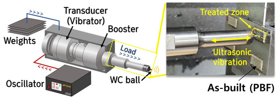
Figure 2.
Experimental procedure for UNSM treatment on as-built specimen.
In the UNSM process, the main parameters that affect surface modification are the total load, number of collisions per area (dependent on the feed rate and inter-pass interval), ball tip diameter, and amplitude and frequency of ultrasonic waves. For these parameters, optimal conditions must be derived and applied depending on the material. In this study, the ball tip diameter, inter-pass interval, and static load were set as control variables. Based on previous studies, a frequency of 30 kHz and amplitude of 30 µm were set as fixed variables in this study.
2.3. Design of Experiment
2.3.1. Response Surface Methodology (RSM)
In statistics, the RSM explores the relationships between several explanatory variables and one or more response variables. The method was introduced by George E. P. Box and K. B. Wilson in 1951 [24,25]. The main idea of the RSM is to use a sequence of designed experiments to obtain an optimal response. Box and Wilson suggested using a second-degree polynomial model to do this. They acknowledged that this model is only an approximation, but they used it because it is easy to estimate and apply, even when little is known about the process. Statistical approaches such as the RSM can be employed to maximize the production of a special substance by optimizing the operational factors. Recently, the RSM alongside proper design of experiments has been extensively used for formulation optimization [26]. In contrast to conventional methods, the interaction among process variables can be determined using statistical techniques [27].
An easy way to estimate a first-degree polynomial model is to use a factorial experiment or fractional factorial design. This is sufficient to determine which explanatory variables affect the response variable(s) of interest. Once it is suspected that only significant explanatory variables remain, a more complicated design, such as the BBD, can be implemented to estimate a second-degree polynomial model, which is still only an approximation at best. In this instance, the relationship between the levels of each factor must be expressed as a curvature to derive the optimal conditions for the response value. Therefore, the regression model function generally adopts a second-degree polynomial regression model to consider this curvature relationship. The second-degree model can be used to optimize (maximize, minimize, or attain a specific target for) the response variable(s) of interest.
2.3.2. Box–Behnken Design (BBD)
The BBD is an independent, rotatable quadratic design with no embedded factorial or fractional factorial points where the variable combinations are at the midpoints of the edges of the variable space and at the center [28,29]. In the present study, by employing the Box–Behnken statistical experiment design and the RSM, the effects of the three independent variables (ball tip diameter of 2.38–6.0 mm, inter-pass interval of 10–90 mm, and load of 10–50 N) on the response (surface roughness and hardness) were investigated, and the optimal conditions were determined to minimize roughness and maximize hardness. For single factor analysis, independent variables and their ranges were selected. Experiments were established based on a BBD with three factors at three levels, and each independent variable was coded at three levels of −1, 0, and +1 as shown in Table 2.

Table 2.
Coded process parameters and their levels.
The experimental design is outlined in Table 3 as an experimental sample for the BBD. The experiment consisted of 15 experimental designs set by randomization. UNSM was applied to the PBFed 316 L surface according to the experimental design, as shown in Figure 2, and the changes in the surface characteristics were analyzed.

Table 3.
Design of experiment with three parameters.
2.4. Experimental Details
The purpose of this study was to find the optimal UNSM conditions that most improve a deposited surface using RSM. Surface roughness and hardness were selected as response values to analyze changes in surface characteristics before and after UNSM treatment. To measure the roughness of the deposited surface, a contact-type surface roughness meter (Mitutoyo, SJ-410, Tokyo, Japan) and 3D surface roughness meter (Contour GT-X, Bruker, Billerica, MA, USA) were used. For each specimen, the roughness was measured ten times, and the average was adopted as a response value. In addition, Minitab 18 software was used to derive the optimal process conditions.
The hardness before and after UNSM treatment was measured using a micro-Vickers hardness tester from Mitutoyo (Hv-112), and indentation was performed for ten seconds using a load of 0.1 kgf. In addition, the hardness in a cross section was measured in the height direction to examine the hardness inside the material after UNSM treatment (Figure 3). As pretreatment each specimen was cut, mounted, and then polished to #2000 grit using silicon carbide (SiC) sandpaper. Finally, it was polished using 1 and 3 µm diamond suspensions. Upon completion of all pretreatments, the hardness was measured at 20 μm intervals in the depth direction from the point 20 µm away from the top surface subjected to UNSM treatment. In this instance, ten measurements were performed at each depth, and the average values were used as representative values.

Figure 3.
Preparation of specimens for measurement of hardness and roughness.
An etching solution (HNO3: 79.36 mL and distilled water: 20.64 mL) was used at an applied voltage and current of 2 V and 2 A, respectively. The microstructure of the etched surface was examined using a field emission scanning electron microscope (FE-SEM, MIRA3, TESCAN). Additionally, EBSD analyses (JSM-7001F; step size 1.8 µm) were performed to determine the phases and phase fraction.
3. Experimental Results
3.1. Changes in Surface Topography
Figure 4a shows SEM images of the deposited surface and surface of the UNSM-treated specimen. In the as-built (PBF) specimen, the formation of spatters can be seen along the deposited track direction, which resulted from the instability of the melt pool generated by laser irradiation on the metal powder [30]. In the PBF process, the melt pool is formed along the transfer direction of the laser nozzle, and it rapidly cools down to form a solidified deposited track after the nozzle passes. Convection occurs inside the melt pool due to the thermal energy introduced during the laser process, molten metal powder, and rapid cooling caused by the local temperature difference [31,32]. During this process, some of the molten metal is discharged to the outside by the vapor pressure remaining inside the melt pool and solidifies to form spatters. The spatters and track overlap formed along the deposited track make the deposited surface irregular [33]. Such a surface topology is often found in the process of melting metals using a laser. Meanwhile, un-melted powder attached to the surface can also be observed in addition to the spatters, and un-melted powder can also be attached to the surface during the process of selective laser melting of one layer and then spreading powder on it using a recoater for the deposition of the next layer.
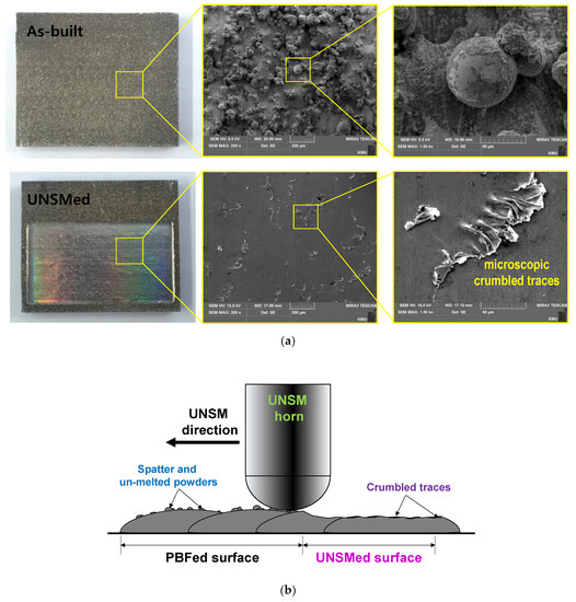
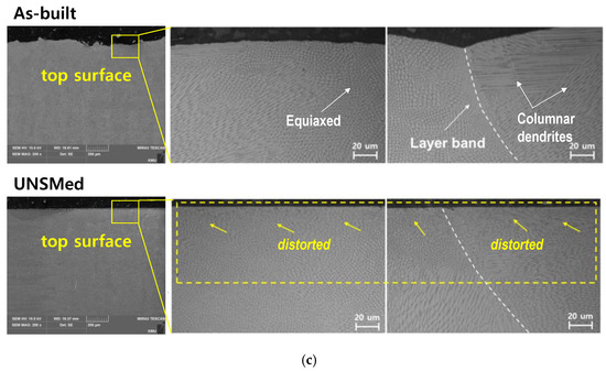
Figure 4.
(a) Fabricated samples and SEM images of as-built and UNSMed specimens, (b) schematic of modification of as-built surface, and (c) SEM images of cross-sections of top surface.
Meanwhile, unlike the as-built specimen with dark color, a glossy surface can be observed in the UNSM-treated area. In particular, the surface of the UNSMed sample shows that the irregular surface of the as-built specimen due to the spatters and un-melted powder was clearly improved by UNSM treatment. Figure 4b shows that the as-built surface became smooth as the spatters and un-melted powder on it were compressed by the impact of the ball tip. The crumbed traces left during the process of compressing the spatters and un-melted powder can be observed from the surface of the UNSMed sample. Such microscopic crumbled traces are expected to affect the surface roughness.
Figure 4c shows a cross-sectional image of the microstructure in the near-surface layer. In the as-build specimen, an equiaxed structure can be observed at the center of the deposited track, with columnar dendrite structures mainly formed on the outer sides (around the layer bands) of the deposited beads. Examination of the locations and orientations of the columnar dendrites reveals differing solidification rates between the center and outer sides of the beads. In addition, the equiaxed structures at the center of the deposited beads are finer than the outer columnar dendrites. The columnar dendrites grow from the outer edge toward the center, which also attests to differing cooling rates between the center and outer sides. Meanwhile, in the UNSMed sample, severe plastic deformation can be observed to occur in the UNSM direction. The high-magnified images show that the microstructures of the UNSM-treated surface are distorted up to a certain depth.
Figure 5 shows X-ray diffractograms of the microstructures and microstructural phases formed on the surfaces of the as-built and UNSMed specimen. Hence, it was confirmed that the phase mainly constituting as-built is austenite (γ). In addition, several peaks were observed. After UNSM treatment, the austenite phase decreased notably. This phenomenon occurred because severe plastic deformation was induced on the austenite by the UNSM; consequently, the austenite was transformed into martensite. Umemoto [34] reported on a mechanism for martensitic transformation as one cause of the increased fineness of a metal surface structure following severe plastic deformation. Furthermore, the martensitic transformation phenomenon of surface structures occurring in metals and alloys such as pure iron (Tao et al. [35]), AISI 304 (Zhang et al. [36]), and AISI 316 L (Roland et al. [37]) have been discussed.
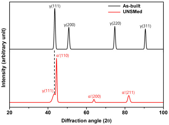
Figure 5.
X-ray diffractograms of as-built and UNSMed specimens.
After the UNSM treatment, the width of the XRD peak increased and the diffraction intensity weakened, as confirmed by Figure 5. This behavior occurred because the surface structure fineness was increased by the UNSM and, also, the crystal lattice became distorted through the occurrence of micro-strain due to the severe plastic deformation (Amanov et al. [15]). Through XRD analysis, it was confirmed that UNSM treatment is a useful means of refining as-built microstructure and grain size.
Figure 6 shows the specimens after the application of UNSM based on the experimental design in Table 3, while Table 4 summarizes the response values of each specimen treated according to the design of experiment in Table 3. For each treatment condition, the surface roughness ranged from an Ra of 1.19 to 4.75 μm, and the hardness ranged from 409 to 473 Hv. The minimum surface roughness and maximum hardness were observed for standard orders #1 and #7, respectively. It was found that the samples subjected to the minimum load exhibited high surface roughness and low hardness. This indicates that the load has a significant influence, which is further analyzed in the next section.
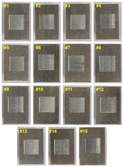
Figure 6.
UNSM-treated specimens according to the design of the experiment.

Table 4.
Response values of each specimen treated according to design of experiment.
3.2. Results of ANOVA
3.2.1. Roughness
Based on Table 4, ANOVA was conducted to derive the second-degree regression model between the factors and roughness response value, and the results are listed in Table 5. In the table, is the roughness response value (in μm), SL is the coded load (in N), IN is the coded interval (in μm), and BT is the coded ball tip diameter (in mm). ANOVA for a regression model was conducted to examine the influence of a factor on the response value, i.e., its significance. For ANOVA, factors with high F-values have a strong influence on the response. The p-value used to analyze the significance of each regression coefficient represents the probability that the F-value will not deviate from the F-distribution [38]. If the F-value deviates from the F-distribution, the test result is judged to be significant. Therefore, a small p-value means that the regression constant is significant because the F-value deviates from the F-distribution. Therefore, for ANOVA, the regression model is judged to be more significant as the F-value increases and p-value decreases [39]. In this instance, the confidence level of the p-value for determining the significance of the regression model was set to 95%. In other words, if the p-value was lower than 0.05, the factor was determined to have a strong influence on the response value.

Table 5.
ANOVA results of roughness.
Because the p-value of the model term, i.e., the entire regression model, is 0.025 (<0.05), the second-degree regression model for Ra is judged to be significant. In addition, because the p-value of the linear term is 0.010 (<0.05), it is judged that there are significant factors among the load (SL), interval (IN), and ball tip diameter (BT). In addition, the p-value of the square term indicates that there is a significant square factor. However, as the p-value of the interaction terms is above 0.05, it can be seen that there is no significant interaction term for . As shown in Table 5, there is no significant term for SL × IN, IN × BT, or SL × BT. Meanwhile, when the p-value of the lack-of-fit term is less than or equal to the significance level, it can be concluded that the regression model does not correctly represent the relationship [39]. Because the p-value of the lack-of-fit term in Table 5 is 0.669 (>0.05), it can be concluded that the regression model for the hardness response was properly derived.
The process of seeking a more suitable model based on ANOVA results is referred to as stepwise regression or pooling [40], and it is possible to derive the final regression model by leaving only significant terms for which the p-value is smaller than the significance level. In this study, the backward elimination method, which gradually removes terms that are not significant in the regression model from the interaction term to the linear model, was used. The interaction term and square term IN × IN, which were not significant, as shown in Table 5, were pooled, and the final derived regression model is as follows:
Ra = 1.811 + 1.785 BT + 0.00355 IN − 0.1634 SL − 0.1923 BT × BT + 0.001996 SL × SL
Although the linear IN term was found to be insignificant in the ANOVA, it was included in the regression model because it is known from previous studies as a factor that affects surface roughness. ANOVA was conducted for the regression model derived through stepwise regression (Equation (1)). It was found that the p-value of the model term of the derived model is zero and that the p-value of the lack-of-fit term is 0.856. Because this is higher than the significance level (0.05), the model is deemed suitable for the response value.
3.2.2. Surface Hardness
Based on Table 4, ANOVA was conducted to derive the second-degree regression model between the factors and surface hardness response value, and the results are listed in Table 6. Because the p-value of the model term, which represents the entire model, is 0.000 and less than 0.05, the second-degree regression model for the surface hardness is deemed significant. In addition, it can be concluded that the regression model was properly derived because the linear, square, and interaction terms in the model are considered significant, and the p-value of the lack-of-fit term is 0.204, which is above the significance level. Comparing the p-values of each UNSM factor, it is possible to identify the influence of each factor on the surface hardness within the set variable domain.

Table 6.
ANOVA results of surface hardness.
As with the surface roughness regression model above, regression analysis was conducted using the backward elimination method based on the results of ANOVA conducted on the surface hardness response. The square term SL × SL, which is not significant, as shown in Table 6, was pooled, and all remaining terms were left in the regression model. As a result, the modified regression model for the surface hardness response value is as follows:
where SH is the surface hardness (Hv). When the ANOVA was conducted on the derived regression model, the p-value of the model term of the modified model was found to be zero, and the p-value of the lack-of-fit term was 0.167. This indicates that the regression model (Equation (2)) was properly derived for the surface hardness response value.
SH = 450.15 − 11.46 BT − 0.8934 IN + 2.191 SL + 1.401 BT × BT + 0.002317 IN × IN + 0.0996 BT × IN − 0.2917 BT × SL − 0.00467 IN × SL
3.3. Analysis of Response Surface
3.3.1. Surface Roughness
Figure 7 shows the response surface and contour plot for the regression model of the surface roughness represented by Equation (1); Figure 7a shows those according to the ball tip diameter and interval. In this instance, the load was fixed at 30 N, which is the mid-level. As shown in the figure, the change in surface roughness due to the ball tip diameter was found to be larger, indicating that the ball tip diameter has a greater influence on surface roughness than the inter-pass interval. This result is in agreement with the ANOVA results in Table 5. The surface roughness was low when the ball tip diameter ranged from 2 to 2.5 mm and the inter-pass interval was less than 40 μm. It also decreased as the ball tip diameter exceeded the 4–5 mm range. The surface roughness was found to improve as the inter-pass interval decreased. Figure 7b shows the response surface of roughness according to the load and ball tip diameter. The inter-pass interval was fixed at 50 μm, which is the mid-level. The surface roughness significantly varied depending on the load and ball tip diameter, and it was found that the influence of the load was slightly higher than that of the ball tip diameter. This agrees with the ANOVA results in Table 5. Figure 7c shows the response surface of roughness according to the inter-pass interval and load. The ball tip diameter was fixed at 4.0 mm, which is the mid-level. It was found that the influence of the load on the surface roughness was higher than that of the inter-pass interval. It must be noted that the surface roughness was almost unchanged by the inter-pass interval. This is in agreement with the p-value of the inter-pass interval factor in Table 5 (above 0.05), and the quadratic term of the inter-pass interval is not significant for the surface roughness response value. The surface roughness decreased as the load increased, and the lowest surface roughness was observed when the inter-pass interval was lower than approximately 20 μm. As can be seen from Figure 7b, the roughness increased again as the load exceeded 40 N. This indicates that the application of a high load to the surface may cause surface irregularities due to plastic deformation of the surface microstructure caused by excessive energy. Finally, the following optimal values for the three conditions to obtain the minimum surface roughness could be derived through RSM: ball tip diameter of 2.38 mm, inter-pass interval of 10 μm, and load of 41 N. The surface roughness that can be obtained under these conditions is expected to be 1.30 μm, which is a significant improvement compared to the roughness of the PBFed specimen before UNSM treatment (20.16 μm).
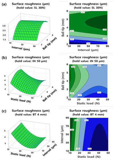
Figure 7.
RSM results for roughness between (a) inter-pass interval and ball tip diameter, (b) load and ball tip diameter, and (c) load and inter-pass interval.
3.3.2. Hardness
Figure 8 shows the surface plot and contour plot for the regression model of the surface hardness response value represented by Equation (2). Figure 8a shows the response surface of hardness according to the ball tip diameter and inter-pass interval. The load was fixed at 30 N, which is the mid-level. The hardness varied significantly depending on the inter-pass interval and ball tip diameter. This agrees with the ANOVA results in Table 6. The hardness increased as the inter-pass interval and ball tip diameter decreased. The response surface of hardness according to the load and ball tip diameter (Figure 8b) also shows that the hardness significantly varied depending on these two parameters. The hardness increased as the ball tip diameter decreased and increased as the load increased. The hardness significantly varied as the strain energy density E increased because the amount of strain energy transmitted to the surface increased; thus, the microstructures were refined more easily, as shown in Equation (2). Figure 8c shows the response surface of hardness according to the inter-pass interval and load. This response surface is similar to that shown in Figure 8a. The hardness varied significantly depending on the inter-pass interval and load. The hardness increased as the inter-pass interval decreased and load increased. Because the transmitted energy density can be maximized at high loads and low inter-pass intervals, the hardness was significantly increased by grain refinement, strain hardening, and an increase in compressive residual stress due to the energy increase. Finally, the following optimal values for the three conditions to obtain the maximum surface hardness could be derived through RSM: ball tip diameter of 2.38 mm, inter-pass interval of 10 μm, and load of 50 N. The obtainable surface hardness under these conditions is expected to be 504 Hv, which is significantly improved compared to the hardness of the PBFed specimen before UNSM treatment (250 Hv).
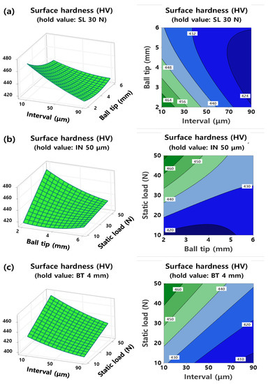
Figure 8.
RSM results for hardness between (a) inter-pass interval and ball tip diameter, (b) load and ball tip diameter, and (c) load and inter-pass interval.
3.4. Multi-Objective Optimization
RSM finds the optimal conditions for factors to achieve the desired response value by deriving a regression model between the factors and response value and analyzing changes in the response value depending on the factors. This study aimed to find optimal conditions for UNSM treatment that can improve the surface roughness and hardness most significantly. A desirability function can be considered to determine the optimal conditions for multiple objective functions. In this study, the minimum surface roughness and maximum hardness were set as objective functions. A desirability function can be defined as Equation (3) [41], where is the response, is the target, is the upper value, and is the weight. The desirability has a value between 0 and 1, and it represents the target as it gets closer to 1. In this study, response optimization was performed to determine the optimal conditions for the regression models of Equations (1) and (2) by setting the weight for the hardness and surface roughness response values to .
Figure 9 shows the results of the response optimization for surface roughness and hardness. A load of 41.11 N, interval of 10 μm, and ball tip diameter of 2.38 mm were derived as the conditions that improve surface roughness and hardness most significantly. Under these optimal conditions, the hardness was predicted to be 490 Hv (desirability for SH = 100%), and the roughness was predicted to be 1.30 μm (desirability for Ra = 96.94%). The composite desirability for these is 98.46%, which is close to the maximum. According to previous single-objective optimization results, the optimal conditions for roughness were a ball tip diameter of 2.38 mm, interval of 10 μm, and load of 41 N, and the expected surface roughness under these conditions was 1.30 μm. For hardness, the derived optimal conditions were a ball tip diameter of 2.38 mm, interval of 10 μm, and load of 50 N, and the expected hardness under these conditions was 504 Hv. In the results for both single-objective optimization and multi-objective optimization, the same conditions were derived for the ball tip diameter and interval. However, for the optimal load condition, 50 N was derived in the single-objective optimization for hardness, while 41.11 N was derived in the multi-objective optimization for surface roughness improvement. This demonstrates the ability of multi-objective optimization to improve surface roughness and hardness simultaneously. Nevertheless, a high hardness of 490 Hv could be obtained as the final expected hardness. Consequently, the optimal conditions by multi-objective optimization were favored. However, considering the minimum units of the parameters that could be set in the experiment, a load of 40 N, interval of 10 μm, and ball tip diameter of 2.38 mm were selected as the final optimal conditions.
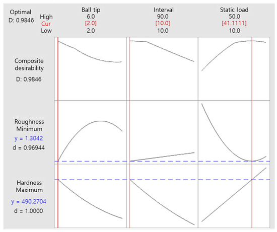
Figure 9.
Results of multi-objective optimization of surface roughness and hardness.
3.5. Experimental Validation
3.5.1. Roughness
A validation experiment was performed for the optimal conditions selected through response optimization. The surfaces of five PBFed samples were subjected to UNSM treatment under the optimal conditions. For comparison, specimens were prepared by applying machining to the surface of a material manufactured by PBF as post-processing. In addition, the machined PBFed specimens were subjected to UNSM treatment under the optimal conditions. The hardness and surface roughness were compared for a total of four samples. Figure 10 shows photographs of the four samples. The photographs show that the rough surface of the PBFed sample was modified by machining and UNSM treatment. The surface roughness of the sample obtained by applying UNSM treatment to the PBFed sample under the optimal conditions (PBFed-UNSM) was found to be 1.3 μm. However, the surface roughness of PBFed-UNSM was higher than that of the sample obtained by applying machining after deposition (PBFed-machined). This appears to be because crumbed traces were left on the surface of the PBFed-UNSMed sample, as shown in the SEM image of the surface of the PBFed-UNSMed specimen in Figure 4a. Meanwhile, the lowest surface roughness could be obtained in the case of UNSM treatment performed after machining (machined-UNSMed). This is because the spatters and un-melted powder on the surface were completely removed by machining, and then the surface was modified more precisely by the impact of the ball tip.
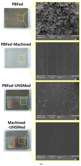
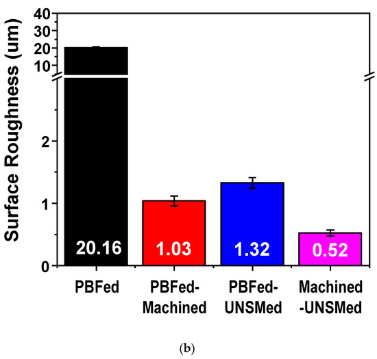
Figure 10.
Comparison of (a) treated surface of each sample and (b) surface roughness for different post-processing approaches.
3.5.2. Hardness
Figure 11 shows the EBSD results for the near-surface microstructure before and after UNSM treatment. It was found that the SUS316L deposited region was mostly composed of austenite [42] and relatively coarse grains (Figure 11a). According to the EBSD results at the same position after UNSM treatment under the optimal conditions (Figure 11b), many dislocations occurred on the surface (up to depths of approximately 60 μm) after UNSM treatment due to severe plastic deformation, and the grains were significantly refined compared to before UNSM treatment. This indicates that UNSM treatment refined the grains due to the plastic deformation of the surface and increased the hardness through strain hardening [43]. According to the Hall–Petch equation, such refined grains increase the strength and hardness of the material [44].
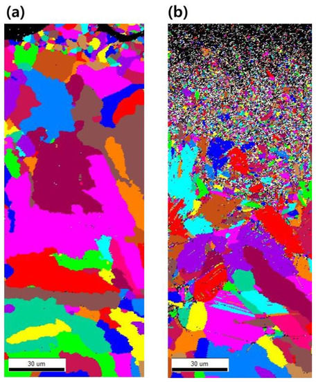
Figure 11.
EBSD results of microstructure near UNSM treated surface: (a) before and (b) after treatment.
Figure 12a shows the change in surface hardness after UNSM treatment. As is already known, machining does not affect the surface hardness. Therefore, the hardness of the PBFed sample did not change after machining. However, it must be noted that the hardness was significantly increased after UNSM treatment (PBFed-UNSMed and machined-UNSMed samples) regardless of machining. Compared to the PBFed sample, the PBFed-UNSMed and machined-UNSMed sample exhibited 98.44% and 105.25% higher hardness, respectively. The surface hardness of the machined-UNSM was approximately 3.43% higher than that of PBFed-UNSM. This appears to be because spatters and un-melted powder were present on the surface of the PBFed sample without machining, and some of the energy transmitted by the impact of the ball tip contributed to the compression of the spatters and un-melted powders. For the machined-UNSMed sample, it is estimated that all of the energy transmitted by the impact of the ball tip was used for microstructure refinement and modification because spatters and un-melted powder were removed by machining.
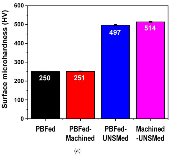
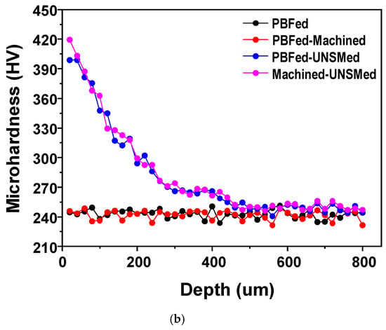
Figure 12.
Comparison of (a) surface hardness of each sample and (b) microhardness variation with depth from top surface according to different treatments.
Figure 12b shows the hardness distribution in the cross-section of each sample according to the depth from the surface. As shown in the figure, the samples treated with UNSM exhibited higher hardness than those without UNSM treatment up to a depth of approximately 500 μm. The increase in hardness gradually decreased as the measuring location deepened, which is attributed to being farther away from the top surface directly affected by the horn, and the effect of UNSM was observed up to a depth of 500 μm.
The above results show that machining is more effective than UNSM treatment for improving the surface roughness after PBF. However, considering the increase in hardness due to UNSM treatment, UNSM treatment can also be used as a post-process for PBFed materials. Of course, UNSM treatment after machining PBFed materials can be proposed as the most effective post-process. However, this causes an increase in production cost due to an additional process. Therefore, it is necessary to select a suitable surface post-processing method considering the surface roughness and mechanical property improvement of the material being manufactured by PBF.
Meanwhile, the PBFed-UNSMed sample exhibited a surface roughness of 1.32 μm and hardness of 497 Hv. These are similar to the expected surface roughness (1.30 μm; error 1.90%) and hardness (490 Hv; error 1.37%) that could be obtained under the optimal UNSM conditions derived through the multi-objective optimization. In other words, the optimal conditions selected through response optimization can effectively modify the deposited surface, and it is possible to predict changes in roughness and hardness in a reasonable manner through the derived mathematical models.
3.5.3. Scratch Test
Figure 13 shows the SEM images of each sample and 3D groove shapes around the indentation after the scratch test. Figure 13a,b shows the scratch test results of the samples without UNSM treatment, while Figure 13c,d shows the results of the samples treated with UNSM. UNSM treatment was performed under the optimal conditions, as described above. In the case of Figure 13a, the scratch test was not possible because of the large number of spatters, un-melted powder, and deposited track boundaries generated on the PBFed surface. Therefore, it is not reasonable to compare its anti-scratching with those of other samples. In Figure 13b, the PBFed-machined sample shows an improved surface through machining compared to the rough surface of the PBFed sample, but fine traces of machining are left. Figure 13c,d confirm the generation of smooth surfaces by UNSM treatment. However, in the case of the PBFed-UNSMed samples, the crumbed traces caused by the plastic deformation of spatters and un-melted powder, as described above, can be seen. When the scratched depths and areas were compared, it was found that the scratched groove in Figure 13b was the widest and deepest, whereas those of the PBFed-UNSMed and machined-UNSMed samples were relatively small. This can be seen as the surface hardness being improved by UNSM treatment. In addition, the scratched groove of the machined-UNSMed sample was smaller than that of the PBFed-UNSMed sample because of the slight difference in hardness between the samples. Meanwhile, it has been reported that UNSM treatment not only increases hardness due to surface microstructure refinement but also increases the wear resistance and scratch resistance due to the micro-dimples generated on the surface [6].
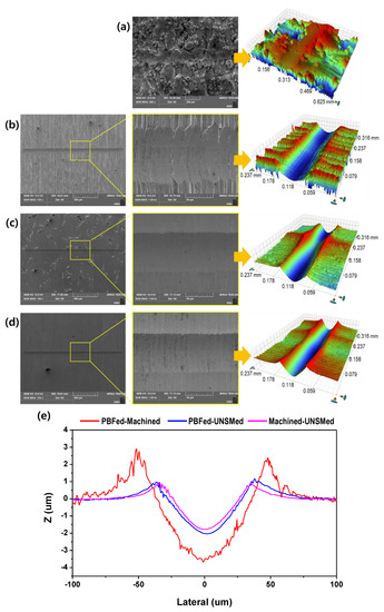
Figure 13.
SEM images and 2D/3D groove shapes after scratch test: (a) as-built (PBF), (b) PBFed-machined, (c) PBFed-UNSMed, (d) machined-UNSMed, and (e) 2D profiles of the scratched grooves.
4. Discussion
According to RSM and ANOVA results, the surface hardness improvement increased as the inter-pass interval and ball tip diameter decreased and load increased. As for the change in surface roughness before and after UNSM treatment, the roughness improvement increased as the load and ball tip diameter decreased. However, it was confirmed that the effect decreased when the load was excessively high or low. This means that increasing the load significantly to maximize the increase in hardness may aggravate the surface roughness. Therefore, the selection of UNSM conditions is important for improving both the surface roughness and hardness, for which the properties of the material, such as strength and elongation, must be considered.
In addition, RSM and BBD were applied in this study to derive optimal conditions that can most significantly improve the surface hardness and roughness. Based on this, mathematical models for predicting the surface roughness and hardness implemented through the application of UNSM were presented through regression analysis and ANOVA and were validated. In this study, multiple response optimizations to most significantly improve both surface roughness and hardness were performed. Consequently, it was possible to improve both the surface roughness and hardness of the deposited surface under the optimal conditions. The sample obtained by applying UNSM treatment to the PBFed sample under the optimal conditions (PBFed-UNSMed sample) exhibited a surface roughness of 1.32 μm and hardness of 497 Hv. The surface roughness decreased by 93.41% and hardness increased by 98.44% compared to those of the PBFed sample without post-processing.
However, compared to the specimen treated with UNSM after machining (machined-UNSMed sample), the surface roughness was 49.42% higher and hardness was 3.43% lower. In particular, the improvement in roughness of the PBFed-UNSMed sample was insufficient compared to the machined-UNSMed sample. Therefore, the surface modified through UNSM after deposition cannot be applied to precision machine components that require superior surface roughness. In other words, machining after AM by PBF can be more effective than UNSM treatment in improving surface roughness. However, considering the increase in hardness due to UNSM treatment, UNSM treatment can also be used as post-processing for PBFed materials. The application of both machining and UNSM can be used as a post-processing method for maximizing the improvement in surface roughness and hardness. However, this may cause an increase in production cost due to the additional post-processing. Therefore, it is necessary to select a suitable post-processing method considering the changes in surface roughness and mechanical properties due to UNSM treatment, as confirmed by the above comparative experiment results. In future work, a methodology for UNSM treatment that can further improve the surface roughness of deposited material without machining should be investigated.
5. Conclusions
In this study, UNSM was applied without post-processing after deposition to improve the surface quality of material additively manufactured by PBF. UNSM was applied to a surface deposited with stainless steel 316 L powder under different process conditions to examine their effects on surface roughness and hardness. According to the results, the following conclusions are drawn.
The surface of the UNSMed sample shows that the irregular surface of the as-built specimen due to the spatters and un-melted powder was clearly improved by UNSM treatment. According to the EBSD results, many dislocations occurred on the surface after UNSM treatment due to severe plastic deformation, and the grains were significantly refined compared to before UNSM treatment.
The RSM results show that the surface roughness is highly dependent on the load and ball tip diameter, and the surface roughness significantly improves as the inter-pass interval and ball tip diameter decrease. Through BBD and ANOVA, the optimal conditions for the improvement of surface characteristics were found to be a load of 40 N, inter-pass interval of 10 μm, and ball tip diameter of 2.38 m.
The surface treated under the optimal conditions exhibited a hardness of 497 Hv and surface roughness of 1.32 μm, which were significantly improved compared to the values for an untreated specimen.
The lowest surface roughness could be obtained in the case of UNSM treatment per-formed after machining (machined-UNSMed). This is because the spatters and un-melted powder on the surface were completely removed by machining, and then the surface was modified more precisely by the impact of the ball tip.
Compared to the PBFed sample, the PBFed-UNSMed and machined-UNSMed sample exhibited 98.44% and 105.25% higher hardness, respectively. UNSM treatment not only increases hardness due to surface microstructure refinement but also increases scratch resistance.
Author Contributions
Writing—original draft, S.-Y.C.; Data curation, S.-Y.C., M.-S.K.; Methodology and Resources, Y.-S.P.; Writing—review & editing, D.-S.S.; Supervision, D.-S.S. All authors have read and agreed to the published version of the manuscript.
Funding
Korea Institute for Advancement of Technology: G02P03040000701, National Research Foundation of Korea: 2021R1A2C101197311.
Institutional Review Board Statement
Not applicable.
Informed Consent Statement
Not applicable.
Data Availability Statement
Data sharing is not applicable to this article.
Acknowledgments
This work was supported by the Korea Institute for Advancement of Technology (KIAT) through the European International R&D Collaboration (grant number G02P03040000701). Additional support through the National Research Foundation of Korea (NRF) under grant number 2021R1A2C101197311 from the Ministry of Science and ICT is gratefully acknowledged.
Conflicts of Interest
The authors declare no conflict of interest.
References
- 3D Printing Scales up. The Economist, 5 September 2013. Available online: https://www.economist.com/technology-quarterly/2013/09/05/3d-printing-scales-up (accessed on 4 April 2021).
- Most Used 3D Printing Technologies 2017–2018|Statistic. Statista. Available online: https://www.statista.com/statistics/560304/worldwide-survey-3d-printing-top-technologies/ (accessed on 2 December 2018).
- Wang, J.; Lin, Y.; Yan, J.; Zen, D.; Zhang, Q.; Huang, R.; Fan, H. Influence of time on the microstructure of AISI 321 austenitic stainless steel in salt bath nitriding. Surf. Coat. Technol. 2012, 206, 3399–3404. [Google Scholar] [CrossRef]
- Lee, I.-S. The Influence of Treatment Condition during Low Temperature Plasma Carburizing of AISI304L Stainless Steel. J. Ocean Eng. Technol. 2011, 25, 56–60. [Google Scholar] [CrossRef][Green Version]
- Kim, Y.S.; Nam, K.W.; Kim, H.S.; Oh, M.S.; Kim, K.S. Mechanical properties of metal/ceramic FGM made by thermal spraying method. J. Power Syst. Eng. 1998, 2, 41–48. [Google Scholar]
- Song, S.H.; Choi, B.H. A study on the characteristics and the prediction of the fatigue strength of the induction surface hardened steel. J. Kor. Soc. Precis. Eng. 2001, 18, 122–130. [Google Scholar]
- Kim, J.-C.; Cheong, S.-K. Microscopic Analysis of Effect of Shot Peening on Corrosion Fatigue Behavior of Aluminum Alloy. Trans. Korean Soc. Mech. Eng. A 2012, 36, 1381–1389. [Google Scholar] [CrossRef]
- Han, M.-S.; Hyun, K.-Y.; Kim, S.-J. Effects of Shot Peening Time on Microstructure and Electrochemical Characteristics for Cu Alloy. J. Korean Soc. Mar. Environ. Saf. 2013, 19, 545–551. [Google Scholar] [CrossRef]
- Wu, J.; Liu, H.; Wei, P.; Zhu, C.; Lin, Q. Effect of shot peening coverage on hardness, residual stress and surface morphology of carburized rollers. Surf. Coat. Technol. 2020, 384, 125273. [Google Scholar] [CrossRef]
- Kim, J.-H.; Lee, W.-R.; Kim, T.-G.; Cheong, S.-K. Micro-Shockwave Measurement and Evaluation of Laser Shock Peening. Trans. Korean Soc. Mech. Eng. B 2011, 35, 1041–1046. [Google Scholar] [CrossRef]
- Kang, H.; Lee, S. Residual compressive stress characteristic using electromagnetic peening of AL6061-O. In Proceedings of the Society of Asian Scientists and Engineers (SASE) 2019 Spring Conference, Pittsburgh, PA, USA, 5–6 March 2019. [Google Scholar]
- Lee, S.-C.; Kim, J.-H.; Kim, H.-D.; Choi, G.-S.; Amanov, A.; Pyun, Y.-S. Changes in Mechanical Properties of WC-Co by Ultrasonic Nanocrystal Surface Modification Technique. J. Korean Soc. Tribol. Lubr. Eng. 2015, 31, 157–162. [Google Scholar] [CrossRef]
- Cho, I.-S.; Lee, C.-S.; Choi, C.-H.; Lee, H.-G.; Lee, M.G.; Jeon, Y. Effect of the Ultrasonic Nanocrystalline Surface Modification (UNSM) on Bulk and 3D-Printed AISI H13 Tool Steels. Metals 2017, 7, 510. [Google Scholar] [CrossRef]
- Kheradmandfard, M.; Kashani-Bozorg, S.F.; Kim, C.L.; Hanzaki, A.Z.; Pyoun, Y.S.; Kim, J.H.; Amanov, A.; Kim, D.E. Nanostructured β-type titanium alloy fabricated by ultrasonic nanocrystal surface modification. Ultrason. Sonochem. 2017, 39, 698–706. [Google Scholar] [CrossRef] [PubMed]
- Lim, T.-H.; Lee, C.-S.; Cho, I.-S.; Amanov, A. Better Surface Integrity and Tribological Properties of Steel Sintered by Powder Metallurgy. Materials 2020, 13, 3172. [Google Scholar] [CrossRef] [PubMed]
- Cao, X.; Xu, X.; Wang, C.; Pyoun, Y.; Wang, Q. Effect of Ultrasonic Surface Impact on the Fatigue Behavior of Ti-6Al-4V Subject to Simulated Body Fluid. Metals 2017, 7, 440. [Google Scholar] [CrossRef]
- Ma, C.; Dong, Y.; Ye, C. Improving surface finish of 3D-printed metals by ultrasonic nanocrystal surface modification. Proc. CIRP 2016, 45, 319–322. [Google Scholar] [CrossRef]
- Amanov, A.; Kim, J.H.; Pyun, Y.S. Microstructure and friction behavior of AISI 52100 and D2 steels subjected to ultrasonic nanocrystalline surface modification (UNSM) technique at a high temperature. Mater. Sci. Forum 2016, 879, 164–168. [Google Scholar] [CrossRef]
- Pyun, S.; Kim, H.S.; Son, K.G.; Song, G.H.; Kim, M.K.; Kang, J.H.; Choi, B.U.; Park, J.; Cho, I.H.; Kim, C.S.; et al. Development of D2 tool steel trimming knives with nanoscale microstructure. Proc. Conf. Mater. Sci. Technol. 2005, 2, 465. [Google Scholar]
- Zhang, H.; Zhao, J.; Liu, J.; Qin, H.; Ren, Z.; Doll, G.; Dong, Y.; Ye, C. The effects of electrically-assisted ultrasonic nanocrystal surface modification on 3D-printed Ti-6Al-4V alloy. Addit. Manuf. 2018, 22, 60–68. [Google Scholar] [CrossRef]
- Kim, M.S.; Oh, W.J.; Baek, G.Y.; Jo, Y.K.; Lee, K.Y.; Park, S.H.; Shim, D.S. Ultrasonic nanocrystal surface modification of high-speed tool steel (AISIM4) layered via direct energy deposition. J. Mater. Process. Technol. 2020, 277, 116420. [Google Scholar] [CrossRef]
- Sanseong, C.H.; Ro, J.S.; Pyoun, Y.S.; Amanov, A. Effects of High-temperature UNSM Treatment on Wear Resistance of Ti-6Al-4V Alloy Prepared by Selective Laser Melting. Tribol. Lubr. 2020, 36, 47–54. [Google Scholar]
- Amanov, A. A promising post-additive manufacturing surface modification for tailoring gradient nanostructure and harmonic structure in Co–Cr–Mo alloy. Vacuum 2020, 182, 109702. [Google Scholar] [CrossRef]
- Box, G.E.P.; Wilson, K.B. On the Experimental Attainment of Optimum Conditions. J. R. Stat. Soc. Ser. B (Stat. Methodol.) 1951, 13, 1–38. [Google Scholar] [CrossRef]
- Box, G.E.P.; Draper, N.R. Response Surfaces, Mixtures, and Ridge Analyses; Wiley: Hoboken, NJ, USA, 2007. [Google Scholar]
- Karmoker, J.R.; Hasan, I.; Ahmed, N.; Saifuddin, M.; Reza, S. Development and Optimization of Acyclovir Loaded Mucoadhesive Microspheres by Box—Behnken Design. Dhaka Univ. J. Pharm. Sci. 2019, 18, 1–12. [Google Scholar] [CrossRef]
- Asadi, N.; Zilouei, H. Optimization of organosolv pretreatment of rice straw for enhanced biohydrogen production using Enterobacter aerogenes. Bioresour. Technol. 2017, 227, 335–344. [Google Scholar] [CrossRef] [PubMed]
- Maran, J.P.; Sivakumar, V.; Sridhar, R.; Immanuel, V.P. Development of model for mechanical properties of tapioca starch based edible films. Ind. Crop. Prod. 2013, 42, 159–168. [Google Scholar] [CrossRef]
- Maran, J.P.; Manikandan, S. Response surface modeling and optimization of process parameters for aqueous extraction of pigments from prickly pear (Opuntia ficusindica) fruit. Dye. Pigment. 2012, 95, 465–472. [Google Scholar] [CrossRef]
- Khairallah, S.A.; Anderson, A.T.; Rubenchik, A.; King, W.E. Laser powder-bed fusion additive manufacturing: Physics of complex melt flow and formation mechanisms of pores, spatter, and denudation zones. Acta Mater. 2016, 108, 36–45. [Google Scholar] [CrossRef]
- Li, Y.; Gu, D. Thermal behavior during selective laser melting of commercially pure titanium powder: Numerical simulation and experimental study. Addit. Manuf. 2014, 1-4, 99–109. [Google Scholar] [CrossRef]
- Zheng, L.; Zhang, Q.; Cao, H.; Wu, W.; Ma, H.; Ding, X.; Yang, J.; Duan, X.; Fan, S. Melt pool boundary extraction and its width prediction from infrared images in selective laser melting. Mater. Des. 2019, 183, 108110. [Google Scholar] [CrossRef]
- Li, C.; Guo, Y.; Zhao, J. Interfacial phenomena and characteristics between the deposited material and substrate in selective laser melting Inconel. J. Mater. Process. Technol. 2017, 243, 269–281. [Google Scholar] [CrossRef]
- Umemoto, M. Nanocrystallization of Steels by Severe Plastic Deformation. Mater. Trans. 2003, 44, 1900–1911. [Google Scholar] [CrossRef]
- Tao, N.; Wang, Z.; Tong, W.; Sui, M.; Lu, J.; Lu, K. An investigation of surface nanocrystallization mechanism in Fe induced by surface mechanical attrition treatment. Acta Mater. 2002, 50, 4603–4616. [Google Scholar] [CrossRef]
- Zhang, H.W.; Hei, Z.K.; Liu, G.; Lu, J.; Lu, K. Formation of nanostructured surface layer on AISI 304 stainless steel by means of surface mechanical attrition treatment. Acta Mater. 2003, 51, 1871–1881. [Google Scholar] [CrossRef]
- Roland, T.; Retraint, D.; Lu, K.; Lu, J. Fatigue life improvement through surface nanostructuring of stainless steel by means of surface mechanical attrition treatment. Scr. Mater. 2006, 54, 1949–1954. [Google Scholar] [CrossRef]
- Carlson, R.R.; Lomax, R.G.; Freed, M.N.; Ryan, J.M.; Hess, R.K. Statistical Concepts: A Second Course for Education and the Behavioral Sciences. Am. Stat. 1993, 47, 308. [Google Scholar] [CrossRef]
- Khuri, A.I.; Cornell, J.A. Response Surfaces: Designs and Analyses; Marcel Dekker, Inc.: New York, NY, USA, 1996. [Google Scholar]
- Dunkler, D.; Plischke, M.; Leffondré, K.; Heinze, G. Augmented backward elimination: A pragmatic and purposeful way to develop statistical models. PLoS ONE 2014, 9, e113677. [Google Scholar] [CrossRef]
- Derringer, G.; Suich, R. Simultaneous Optimization of Several Response Variables. J. Qual. Technol. 1980, 12, 214–219. [Google Scholar] [CrossRef]
- Oh, W.J.; Lee, W.J.; Kim, M.S.; Jeon, J.B.; Shim, D.S. Repairing additive-manufactured 316L stainless steel using direct energy deposition. Opt. Laser Technol. 2019, 117, 6–17. [Google Scholar] [CrossRef]
- Ye, C.; Telang, A.; Gill, A.S.; Suslov, S.; Idell, Y.; Zweiacker, K.; Wiezorek, J.M.; Zhou, Z.; Qian, D.; Mannava, S.R.; et al. Gradient nanostructure and residual stresses induced by Ultrasonic Nano-crystal Surface Modification in 304 austenitic stainless steel for high strength and high ductility. Mater. Sci. Eng. A 2014, 613, 274–288. [Google Scholar] [CrossRef]
- Hall, E.O. The deformation and ageing of mild steel: Ⅲ discussion of results. Proc. Phys. Soc. Sect. B 1951, 64, 747. [Google Scholar] [CrossRef]
Publisher’s Note: MDPI stays neutral with regard to jurisdictional claims in published maps and institutional affiliations. |
© 2021 by the authors. Licensee MDPI, Basel, Switzerland. This article is an open access article distributed under the terms and conditions of the Creative Commons Attribution (CC BY) license (https://creativecommons.org/licenses/by/4.0/).