
An Evaluation Model for Selecting Part Candidates for Additive Manufacturing in the Transport Sector


Abstract
1. Introduction
1.1. AM Opportunities in the Production of Transport Equipment Parts
1.1.1. Production of Lightweight Parts
1.1.2. High Performance Critical Parts
1.1.3. Producing Spare Parts in Low Volume
1.1.4. Production Tools with Special Features
1.2. Importance of Selecting Parts for AM Application
2. Parameters for Selecting Part Candidates for AM Application
2.1. Geometric Complexity
2.2. Value of the Part
2.3. Production Volume
2.4. Lightweight Design
2.5. High Performance Material Change
2.6. Improved Efficiency
2.7. Reducing the Number of Components in an Assembly
2.8. Material Usage
2.9. Function of the Part
2.10. Time to Manufacture Component
2.11. Size of the Part
3. Development of the Evaluation Model
3.1. The Analytic Hierarchy Process
3.2. Application of the AHP Method to Assign Weights to Criteria
3.3. Proposed Evaluation Method
4. Evaluation of Model
4.1. Case Studies
4.1.1. Case Study 1
4.1.2. Case Study 2
4.1.3. Case Study 3
4.1.4. Case Study 4
4.2. Validation of Model Using Case Studies
4.3. Results and Discussion
5. Conclusions
- The opportunities offered by AM in the production of transport equipment parts were explained using previous studies from the literature. These include producing high performance parts with improved designs and high value parts which are produced in low volumes.
- An evaluation model for choosing part candidates for AM application in the transport sector was developed. To formulate the mode, the AHP processes was used to rank the criteria and assign weights depending on the needs of the transport equipment manufacturing industry. The criteria used were obtained from previous studies.
- Different case studies from the literature were used to validate the proposed decision matrix. The calculated weights obtained from the various case studies were in agreement with the evaluation model. Hence, the proposed model is a suitable tool that can be used to guide the user to identify parts suitable for AM application.
- The proposed method is not only useful for identifying parts for AM application but also gives direction on value addition of the selected part candidates through design improvement. Hence, this study will add to the understanding of how transport equipment manufacturing industries can effectively screen potential part candidates and obtain value, thereby promoting the overall sustainability of the AM process in terms of material conservation, cost effectiveness, and functionality.
- The study will add to the understanding of how transport equipment manufacturing industries can effectively screen potential part candidates, thereby promoting the overall sustainability of the AM process in terms of material conservation, cost effectiveness, and functionality.
- Future studies should include a thorough cost–benefit analysis to further provide the economic justification of the proposed model.
Author Contributions
Funding
Institutional Review Board Statement
Informed Consent Statement
Data Availability Statement
Acknowledgments
Conflicts of Interest
References
- Machado, C.G.; Winroth, M.P.; Da Silva, E.H.D.R. Sustainable manufacturing in Industry 4.0: An emerging research agenda. Int. J. Prod. Res. 2020, 58, 1462–1484. [Google Scholar] [CrossRef]
- Leal, R.; Barreiros, F.M.; Alves, L.; Romeiro, F.; Vasco, J.C.; Santos, M.; Marto, C. Additive manufacturing tooling for the automotive industry. Int. J. Adv. Manuf. Technol. 2017, 92, 1671–1676. [Google Scholar] [CrossRef]
- Killen, A.; Fu, L.; Coxon, S.; Napper, R. Exploring the use of Additive Manufacturing in Providing an Alternative Approach to the Design, Manufacture and Maintenance of Interior Rail Components. In Proceedings of the 40th Australasian Transport Research Forum (ATRF), Darwin, Australia, 30 October–1 November 2018. [Google Scholar]
- Yusuf, S.M.; Cutler, S.; Gao, N. Review: The Impact of Metal Additive on the Aerospace Industry. Metals 2019, 9, 1–35. [Google Scholar]
- Black, A.H.; Makundi, B.; McLennan, T. Africa’s Automotive Industry: Potential and Challenges. African Development Bank. 2017, pp. 1–17. Available online: https://www.afdb.org/en/documents/publications/working-paper-series/ (accessed on 5 February 2021).
- The Observatory of Economic Complexity (OEC) South Africa. 2021. Available online: https://oec.world/en/profile/country/zaf (accessed on 23 March 2020).
- Huang, R.; Riddle, M.; Graziano, D.; Warren, J.; Das, S.; Nimbalkar, S.; Cresko, J.; Masanet, E. Energy and emissions saving potential of additive manufacturing: The case of lightweight aircraft components. J. Clean. Prod. 2016, 135, 1559–1570. [Google Scholar] [CrossRef]
- Zanoni, S.; Ashourpour, M.; Bacchetti, A.; Zanardini, M.; Perona, M. Supply chain implications of additive manufacturing: A holistic synopsis through a collection of case studies. Int. J. Adv. Manuf. Technol. 2019, 102, 3325–3340. [Google Scholar] [CrossRef]
- Ford, S.L.N. Additive Manufacturing Technology: Potential Implications for US Manufacturing. J. Int. Commer. Econ. 2014, 6, 1–35. [Google Scholar]
- Yadroitsev, I.; Krakhmalev, P.; Yadroitsava, I. Selective laser melting of Ti6Al4V alloy for biomedical applications: Temperature monitoring and microstructural evolution. J. Alloy. Compd. 2014, 583, 404–409. [Google Scholar] [CrossRef]
- du Plessis, A.; Yadroitsava, I.; Yadroitsev, I. Ti6Al4V lightweight lattice structures manufactured by laser powder bed fusion for load-bearing applications. Opt. Laser Technol. 2018, 108, 521–528. [Google Scholar] [CrossRef]
- Yadroitsev, I.; Yadroitsava, I.; Bertrand, P.; Smurov, I. Factor analysis of selective laser melting process parameters and geometrical characteristics of synthesized single tracks. Rapid Prototyp. J. 2012, 18, 201–208. [Google Scholar] [CrossRef]
- Hagedorn-Hansen, D.; Cichon, R.; Bezuidenhout, M.B.; Hugo, P.A.; Oosthuizen, G.A. Geometric deviation of hy-brid parts produced by selective laser melting. S. Afr. J. Ind. Eng. 2015, 1, 1–9. [Google Scholar]
- Mugwagwa, L.; Dimitrov, D.; Matope, S.; Yadroitsev, I. Evaluation of the impact of scanning strategies on residual stresses in selective laser melting. Int. J. Adv. Manuf. Technol. 2019, 102, 2441–2450. [Google Scholar] [CrossRef]
- Liu, R.; Wang, Z.; Sparks, T.; Liou, F.; Newkirk, J. Aerospace applications of laser additive manufacturing. In Laser Additive Manufacturing; Elsevier: Amsterdam, The Netherlands, 2017; pp. 351–371. [Google Scholar]
- Negi, S.; Dhiman, S.; Sharma, R.K. Basics, applications and future of additive manufacturing technologies: A review. J. Manuf. Technol. Res. 2012, 5, 75. [Google Scholar]
- Gao, W.; Zhang, Y.; Ramanujan, D.; Ramani, K.; Chen, Y.; Williams, C.B.; Wang, C.C.; Shin, Y.C.; Zhang, S.; Zavattieri, P.D. The status, challenges, and future of additive manufacturing in engineering. Comput. Des. 2015, 69, 65–89. [Google Scholar] [CrossRef]
- Orme, M.E.; Gschweitl, M.; Ferrari, M.; Madera, I.; Mouriaux, F. Designing for additive manufacturing: Light-weighting through topology optimization enables lunar spacecraft. J. Mech. Des. 2017, 139, 100905–100911. [Google Scholar] [CrossRef]
- Miracle, D. Lightweighting and the Future of Aerospace Metals. In Kinetics of Metallurgical Processes; Metzler, J.B., Ed.; Springer: Singapore, 2019; pp. 27–38. [Google Scholar]
- Plocher, J.; Panesar, A. Review on design and structural optimisation in additive manufacturing: Towards next-generation lightweight structures. Mater. Des. 2019, 183, 108164. [Google Scholar] [CrossRef]
- Kim, G.-W.; Park, Y.-I.; Park, K. Topology Optimization and Additive Manufacturing of Automotive Component by Coupling Kinetic and Structural Analyses. Int. J. Automot. Technol. 2020, 21, 1455–1463. [Google Scholar] [CrossRef]
- Shi, G.; Chengqi, G.U.A.N.; Dongliang, Q.U.A.N.; Dongtao, W.U.; Lei, T.A.N.G.; Tong, G.A.O. An aerospace bracket designed by thermo-elastic topology optimization and manufactured by additive manufacturing. Chin. J. Aeronaut. 2020, 33, 1252–1259. [Google Scholar] [CrossRef]
- Calleja-Ochoa, A.; Gonzalez-Barrio, H.; de Lacalle, N.L.; Martínez, S.; Albizuri, J.; Lamikiz, A. A New Approach in the Design of Microstructured Ultralight Components to Achieve Maximum Functional Performance. Materials 2021, 14, 1588. [Google Scholar] [CrossRef]
- Sarvankar, S.G.; Yewale, S.N. Additive Manufacturing in Automobile Industry. Int. J. Res. Aeronaut. Mech. Eng. 2019, 7, 1–10. [Google Scholar]
- Calleja, A.; Tabernero, I.; Ealo, J.A.; Campa, F.J.; Lamikiz, A.; De Lacalle, L.N.L. Feed rate calculation algorithm for the homogeneous material deposition of blisk blades by 5-axis laser cladding. Int. J. Adv. Manuf. Technol. 2014, 74, 1219–1228. [Google Scholar] [CrossRef]
- Knofius, N.; Van Der Heijden, M.; Zijm, W. Consolidating spare parts for asset maintenance with additive manufacturing. Int. J. Prod. Econ. 2019, 208, 269–280. [Google Scholar] [CrossRef]
- Frandsen, C.S.; Nielsen, M.M.; Chaudhuri, A.; Jayaram, J.; Govindan, K. In search for classification and selection of spare parts suitable for additive manufacturing: A literature review. Int. J. Prod. Res. 2020, 58, 970–996. [Google Scholar] [CrossRef]
- Khajavi, S.H.; Partanen, J.; Holmström, J. Additive manufacturing in the spare parts supply chain. Comput. Ind. 2014, 65, 50–63. [Google Scholar] [CrossRef]
- Chantzis, D.; Liu, X.; Politis, D.J.; El Fakir, O.; Chua, T.Y.; Shi, Z.; Wang, L. Review on additive manufacturing of tooling for hot stamping. Int. J. Adv. Manuf. Technol. 2020, 109, 87–107. [Google Scholar] [CrossRef]
- Tian, T.; Huang, X.; Cheng, K.; Liang, Y.; Hu, S.; Yao, L.; Guan, D.; Xu, Y.; Liu, P. Flexible and Reconfigurable Frequency Selective Surface with Wide Angular Stability Fabricated With Additive Manufacturing Procedure. IEEE Antennas Wirel. Propag. Lett. 2020, 19, 2428–2432. [Google Scholar] [CrossRef]
- Singh, A.; Gupta, P.; Asjad, M. Reconfigurable Manufacturing System (RMS): Accelerate Towards Industries 4. In Proceedings of the International Conference on Sustainable Computing in Science, Technology and Management (SUSCOM), Amity University Rajasthan, Jaipur, India, 26–28 February 2019. [Google Scholar]
- Gebauer, M.; Stoll, P.; Spierings, A.; Müller, B.; Polster, S.; Feld, T.; Zurbrügg, A. High performance sheet metal forming tooling by additive manufacturing. In Proceedings of the iCAT 2016 6th International Conference on Additive Technologies, Nurnberg, Germany, 29–30 November 2016; pp. 354–361. [Google Scholar]
- Marin, F.; de Souza, A.F.; Ahrens, C.H.; de Lacalle, L.N.L. A new hybrid process combining machining and selec-tive laser melting to manufacture an advanced concept of conformal cooling channels for plastic injection molds. Int. J. Adv. Manuf. Technol. 2021, 113, 1561–1576. [Google Scholar] [CrossRef]
- Schmidt, M.; Merklein, M.; Bourell, D.; Dimitrov, D.; Hausotte, T.; Wegener, K.; Overmeyer, L.; Vollertsen, F.; Levy, G.N. Laser based additive manufacturing in industry and academia. CIRP Ann. 2017, 66, 561–583. [Google Scholar] [CrossRef]
- Lindemann, C.; Reiher, T.; Jahnke, U.; Koch, R. Towards a sustainable and economic selection of part candidates for additive manufacturing. Rapid Prototyp. J. 2015, 21, 216–227. [Google Scholar] [CrossRef]
- Klahn, C.; Leutenecker, B.; Meboldt, M. Design for additive manufacturing–supporting the substitution of compo-nents in series products. Procedia Cirp. 2014, 21, 138–143. [Google Scholar] [CrossRef]
- Booth, J.W.; Alperovich, J.; Chawla, P.; Ma, J.; Reid, T.N.; Ramani, K. The Design for Additive Manufacturing Worksheet. J. Mech. Des. 2017, 139, 100904. [Google Scholar] [CrossRef]
- Reiher, T.; Lindemann, C.; Jahnke, U.; Deppe, G.; Koch, R. Holistic approach for industrializing AM technology: From part selection to test and verification. Prog. Addit. Manuf. 2017, 2, 43–55. [Google Scholar] [CrossRef]
- Yang, S.; Santoro, F.; Sulthan, M.A.; Zhao, Y.F. A numerical-based part consolidation candidate detection approach with modularization considerations. Res. Eng. Des. 2018, 30, 63–83. [Google Scholar] [CrossRef]
- Materialise 5 Parameters That Decide the Success of Your 3D Printing Project. 2014. Available online: https://www.materialise.com/en/blog/5-parameters-decide-success-of-your-3d-printing-project (accessed on 26 January 2021).
- Yao, X.; Moon, S.K.; Bi, G. A hybrid machine learning approach for additive manufacturing design feature recommendation. Rapid Prototyp. J. 2017, 23, 983–997. [Google Scholar] [CrossRef]
- Merkt, S.; Hinke, C.; Schleifenbaum, H.; Voswinckel, H. Geometric complexity analysis in an integrative technology evaluation model (item) for selective laser melting (slm)#. S. Afr. J. Ind. Eng. 2011, 23, 97–105. [Google Scholar] [CrossRef]
- Cruz, M.F.; Borille, A.V. Decision methods application to compare conventional manufacturing process with metal additive manufacturing process in the aerospace industry. J. Braz. Soc. Mech. Sci. Eng. 2017, 39, 177–193. [Google Scholar] [CrossRef]
- Yang, S.; Page, T.; Zhang, Y.; Zhao, Y.F. Towards an automated decision support system for the identification of additive manufacturing part candidates. J. Intell. Manuf. 2020, 31, 1917–1933. [Google Scholar] [CrossRef]
- Castro, G.; Rodríguez, J.; Montealegre, M.A.; Arias, J.L.; Yañez, A.; Panedas, S.; Rey, L. Laser additive manufactur-ing of high added value pieces. Procedia Eng. 2015, 132, 102–109. [Google Scholar] [CrossRef]
- Uhlmann, E.; Kersting, R.; Klein, T.B.; Cruz, M.F.; Borille, A.V. Additive manufacturing of titanium alloy for air-craft components. Procedia Cirp 2015, 35, 55–60. [Google Scholar] [CrossRef]
- Zhu, L.; Li, N.; Childs, P. Light-weighting in aerospace component and system design. Propuls. Power Res. 2018, 7, 103–119. [Google Scholar] [CrossRef]
- Gu, D. Laser Additive Manufacturing of High-Performance Materials; Springer Science and Business Media LLC: Berlin, Germany, 2015. [Google Scholar]
- Hossain, M.S.; Gonzalez, J.A.; Hernandez, R.M.; Shuvo, M.A.I.; Mireles, J.; Choudhuri, A.; Wicker, R.B. Fabrication of smart parts using powder bed fusion additive manufacturing technology. Addit. Manuf. 2016, 10, 58–66. [Google Scholar] [CrossRef]
- Muvunzi, R. Application of Additive Manufacturing for improved thermal management of hot stamping tools. Ph.D. Thesis, Stellenbosch University, Stellenbosch, South Africa, 2020. [Google Scholar]
- Yang, S.; Tang, Y.; Zhao, Y.F. A new part consolidation method to embrace the design freedom of additive manufacturing. J. Manuf. Process. 2015, 20, 444–449. [Google Scholar] [CrossRef]
- Brandt, M.; Sun, S.J.; Leary, M.; Feih, S.; Elambasseril, J.; Liu, Q.C. High-value SLM aerospace components: From design to manufacture. In Advanced Materials Research; Trans Tech Publications Ltd.: Bäch, Switzerland, 2013; Volume 633, pp. 135–147. [Google Scholar]
- Muvunzi, R.; Hagedorn-Hansen, D.; Matope, S.; Madyibi, X.; Swart, C.B.; Nagel, M. Industry case study: Process chain for manufacturing of a large hybrid hot stamping tool with conformal cooling channels. Int. J. Adv. Manuf. Technol. 2020, 110, 1723–1730. [Google Scholar] [CrossRef]
- Vaidya, O.S.; Kumar, S. Analytic hierarchy process: An overview of applications. Eur. J. Oper. Res. 2006, 169, 1–29. [Google Scholar] [CrossRef]
- Ishizaka, A.; Nemery, P. Multi-Criteria Decision Analysis: Methods and Software; John Wiley & Sons: Hoboken, NJ, USA, 2013. [Google Scholar]
- Brunelli, M. Introduction to the Analytic Hierarchy Process; Springer: New York, NY, USA, 2015. [Google Scholar]
- Caiazzo, F.; Alfieri, V.; Corrado, G.; Argenio, P. Laser powder-bed fusion of Inconel 718 to manufacture turbine blades. Int. J. Adv. Manuf. Technol. 2017, 93, 4023–4031. [Google Scholar] [CrossRef]
- Magerramova, L.; Vasilyev, B.; Kinzburskiy, V. Novel Designs of Turbine Blades for Additive Manufacturing. In Proceedings of the Volume 5C: Heat Transfer, New York, NY, USA, 20 September 2016; ASME International: New York, NY, USA, 2016; pp. 1–7. [Google Scholar]
- Dimitrov, D.; Uheida, E.; Oosthuizen, G.; Blaine, D.; Laubscher, R.; Sterzing, A.; Blau, P.; Gerber, W.; Damm, O.F.R. Manufacturing of high added value titanium components. A South African perspective. In Proceedings of the IOP Conference Series: Materials Science and Engineering, Vanderbijlpark, South Africa, 23–26 October 2018; Volume 430, p. 012009. [Google Scholar]
- Abdi, M.; Ashcroft, I.; Wildman, R.D. Design optimisation for an additively manufactured automotive component. Int. J. Powertrains 2018, 7, 142–161. [Google Scholar] [CrossRef]
- GmbH, C. Oncet Laser ‘Voraus! Topologisch optimierte Bauteile in der Luftfahrt. Ahead! Topologically Optimised Components in Aviation. 2015. Available online: https://www.ge.com/additive/sites/default/files/2018-01/1708_Aerospace_DE-EN_update_2__lowres_einzel.pdf (accessed on 8 March 2021).


| Author(s) | Criteria for Selecting Part Candidates for AM | Type of Method Used |
|---|---|---|
| Klahn et al. [36] | Opportunity for design improvement through:
| Selection of part for AM substitution depended on the opportunities for design improvement. |
| Booth et al. [37] |
| Developed a worksheet for identifying part designs suitable for AM application depending on geometric features. |
| Lindemann et al. [35] |
| Developed a tradeoff matrix to screen parts for AM application and evaluate the benefits. |
| Yang et al. [39] |
| Developed a modularity-based framework for identifying parts and assemblies that can be consolidated using AM. |
| Yao et al. [41] |
| Hybrid machine learning method to select potential parts for AM application depending on geometric features. |
| Merkt et al. [42] |
| Method for measuring geometric complexity and using it to identify potential parts for AM application. |
| Materialise [40] |
| Analysis of parts based on the criteria. |
| Cruz and Borille [43] |
| The criteria were ranked using three decision-making approaches in order to determine whether AM was the most suitable method. |
| Technical | Economic |
|---|---|
Geometric factors
|
|
| Size of part |
|
Need for design improvement through
|
|
|
|
| Criteria. | Classification | ||
|---|---|---|---|
| Geometric Complexity | Low Parts with basic shapes that are similar to common stock materials [37] | Medium Parts which can be machined but require additional operations | High Parts with interior features or those with surface curvatures which are difficult to machine [37] |
| Value of Part | Low | Medium | High |
| Production Volume (per year) | Low ≤1000 | Medium 1000–10,000 | High >10,000 |
Necessity for Design Improvement Through
| None of the design improvement methods are necessary | At least one of the design improvement methods are necessary | More than one of the design improvement methods are necessary |
| Material Removal | Low Less than 50% material removal using conventional processes | Medium 50% material removal using conventional methods | High More than 50% material removal using conventional methods |
| Function of Part | Low Non-critical part | High Critical part | |
| Time to Manufacture Component | Time to produce a part using the conventional processes is less than using AM | Time to produce a part with an AM-integrated process chain is less than using conventional methods | |
| Size of Part | Size of a part can be accommodated into the machine build envelope | The part can be subdivided into segments which can be built separately and assembled without the function | The part is larger than the build envelope and cannot be subdivided |
| Material | Material required for producing the part is not available in powder form | Material required for producing the part is not available in powder form. An alternative AM material can be used without compromising the functionality | Material required for producing the part is available in powder form |
| Level of Importance | Rating |
|---|---|
| Extreme Importance | 9 |
| Very Strong Importance | 7 |
| Strong Importance | 5 |
| Moderate Importance | 3 |
| Equal Importance | 1 |
| Compromise between the above values | 2, 4, 6, 8 |
| n | 1 | 2 | 3 | 4 | 5 | 6 | 7 | 8 | 9 | 10 |
|---|---|---|---|---|---|---|---|---|---|---|
| RI | 0 | 0 | 0.58 | 0.9 | 1.12 | 1.24 | 1.32 | 1.41 | 1.45 | 1.49 |
| Design Improvement | Geometric Complexity | Production Volume | Value of Part | Material Removal | Function | Time to Manufacture | |
|---|---|---|---|---|---|---|---|
| Design improvement | 1 | 1/3 | 1/3 | 1 | 5 | 1 | 4 |
| Geometric complexity | 3 | 1 | 2 | 2 | 6 | 3 | 5 |
| Production Volume | 3 | 1/2 | 1 | 1 | 6 | 5 | 5 |
| Value of the Part | 1 | 1/2 | 1 | 1 | 5 | 1 | 4 |
| Material removal | 1/5 | 1/6 | 1/6 | 1/5 | 1 | 1/5 | 1 |
| Function | 1 | 1/3 | 1/5 | 1 | 5 | 1 | 5 |
| Time to manufacture | 1/4 | 1/5 | 1/5 | 1/4 | 1 | 1/5 | 1 |
| Design Improvement | Geometric Complexity | Production Volume | Value of Part | Material Removal | Function | Time to Manufacture | |
|---|---|---|---|---|---|---|---|
| Design improvement | 0.106 | 0.110 | 0.068 | 0.155 | 0.172 | 0.088 | 0.160 |
| Geometric complexity | 0.317 | 0.330 | 0.408 | 0.310 | 0.207 | 0.263 | 0.200 |
| Production Volume | 0.317 | 0.165 | 0.204 | 0.155 | 0.207 | 0.439 | 0.200 |
| Value of the Part | 0.106 | 0.165 | 0.204 | 0.155 | 0.172 | 0.088 | 0.160 |
| Material removal | 0.021 | 0.055 | 0.034 | 0.031 | 0.034 | 0.018 | 0.040 |
| Function | 0.106 | 0.110 | 0.041 | 0.155 | 0.172 | 0.088 | 0.200 |
| Time to manufacture | 0.026 | 0.066 | 0.041 | 0.039 | 0.034 | 0.018 | 0.040 |
| Criteria | Weight | Consistency Measure | Rank |
|---|---|---|---|
| Geometric complexity | 0.291 | 7.577 | 1 |
| Production Volume | 0.241 | 7.961 | 2 |
| Value of the Part | 0.15 | 7.343 | 3 |
| Function | 0.125 | 7.186 | 4 |
| Design improvement | 0.123 | 7.255 | 5 |
| Material removal | 0.033 | 7.251 | 6 |
| Time to manufacture | 0.038 | 7.122 | 7 |
| Criteria (a) | Weight (C) | Classification | ||
|---|---|---|---|---|
| Geometric Complexity | 0.291 | Low | Medium | High |
| 1 | 2 | 3 | ||
| Production Volume | 0.241 | High | Medium | Low |
| 1 | 2 | 3 | ||
| Function | 0.125 | Non critical | Critical | |
| 1 | 3 | |||
| Opportunity for Design Improvement | 0.123 | None | At least one of the design improvement methods is necessary | More than one of the design improvement methods are necessary |
| 1 | 2 | 3 | ||
| Time to Manufacture | 0.038 | 1 Time to produce part using conventional processes is less than using AM | 3 Time to produce parts with an AM-integrated process chain is less than using conventional methods | |
| Material Removal | 0.033 | Low Less than 50% material removal using conventional processes | Medium 50% material removal using conventional methods | High More than 50% material removal using conventional methods |
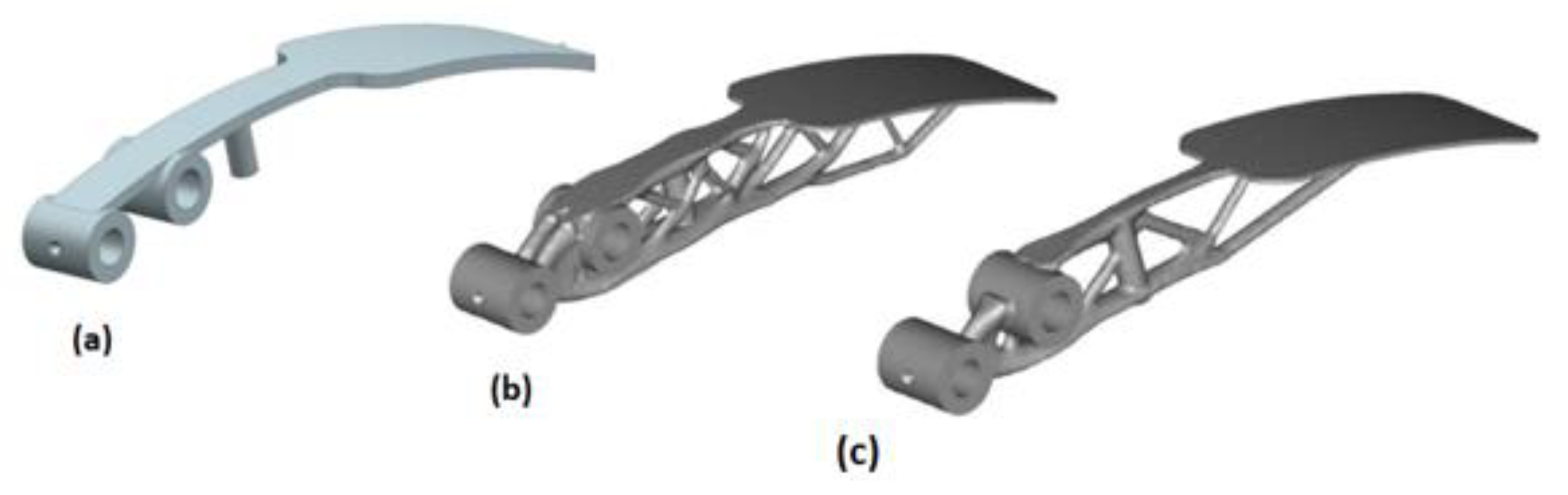
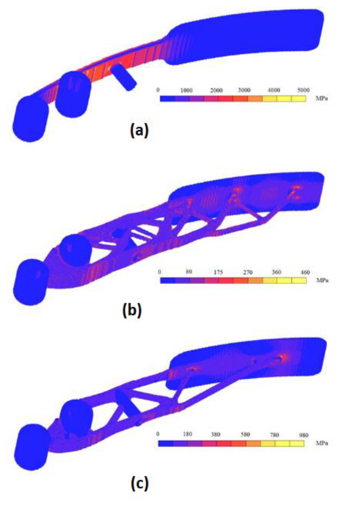
| Volume (m3) | Max Von Mises Stress (MPa) | Compliance | |
|---|---|---|---|
| Existing Pedal (a) | 72.1 | 5012 | 95.312 |
| Optimised Design 1 (b) | 70.8 | 458 | 0.994 |
| Optimised Design 2 (c) | 54.6 | 976 | 2.032 |
| Criteria (a) | Weight (C) | Classification | Case 1 | Case 2 | Case 3 | Case 4 | ||
|---|---|---|---|---|---|---|---|---|
| Geometric Complexity | 0.291 | Low | Medium | High | 0.873 | 0.582 | 0.582 | 0.582 |
| 1 | 2 | 3 | ||||||
| Production Volume | 0.241 | High | Medium | Low | 0.723 | 0.723 | 0.723 | 0.723 |
| 1 | 2 | 3 | ||||||
| Function | 0.125 | Non critical | Critical | 0.375 | 0.375 | 0.375 | 0.375 | |
| 1 | 3 | |||||||
| Opportunity for Design Improvement | 0.123 | None | At least one of the design improvement methods is necessary | More than one of the design improvement methods are necessary | 0.123 | 0.246 | 0.246 | 0.246 |
| 1 | 2 | 3 | ||||||
| Time to Manufacture | 0.038 | Time to produce part using conventional processes is less than using AM | Time to produce parts with AM is less than using conventional methods | 0.114 | 0.038 | 0.038 | 0.114 | |
| 1 | 3 | |||||||
| Material Removal | 0.033 | Low Less than 50% of material removal using conventional processes | Medium 50% of material removal using conventional methods | High More than 50% of material removal using conventional methods | 0.033 | 0.033 | 0.033 | 0.033 |
| Total | 2.208 | 1.997 | 1.997 | 2.073 | ||||
Publisher’s Note: MDPI stays neutral with regard to jurisdictional claims in published maps and institutional affiliations. |
© 2021 by the authors. Licensee MDPI, Basel, Switzerland. This article is an open access article distributed under the terms and conditions of the Creative Commons Attribution (CC BY) license (https://creativecommons.org/licenses/by/4.0/).
Share and Cite
Muvunzi, R.; Mpofu, K.; Daniyan, I. An Evaluation Model for Selecting Part Candidates for Additive Manufacturing in the Transport Sector. Metals 2021, 11, 765. https://doi.org/10.3390/met11050765
Muvunzi R, Mpofu K, Daniyan I. An Evaluation Model for Selecting Part Candidates for Additive Manufacturing in the Transport Sector. Metals. 2021; 11(5):765. https://doi.org/10.3390/met11050765
Chicago/Turabian StyleMuvunzi, Rumbidzai, Khumbulani Mpofu, and Ilesanmi Daniyan. 2021. "An Evaluation Model for Selecting Part Candidates for Additive Manufacturing in the Transport Sector" Metals 11, no. 5: 765. https://doi.org/10.3390/met11050765
APA StyleMuvunzi, R., Mpofu, K., & Daniyan, I. (2021). An Evaluation Model for Selecting Part Candidates for Additive Manufacturing in the Transport Sector. Metals, 11(5), 765. https://doi.org/10.3390/met11050765