
Investigating the Influence of Process Parameters on the Mechanical Properties of Extruded Aluminum Tubes by Cyclic Indentation Tests

 , , , , and
Abstract
1. Introduction
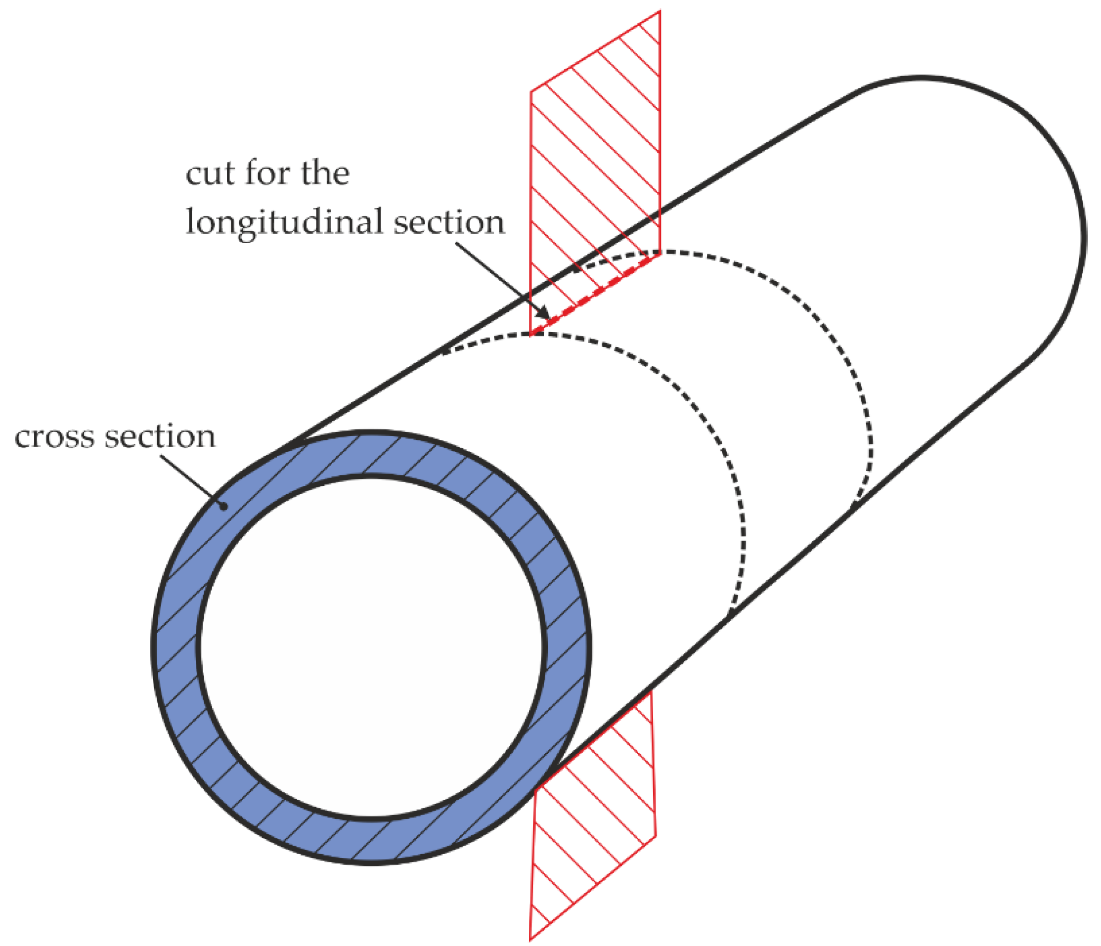
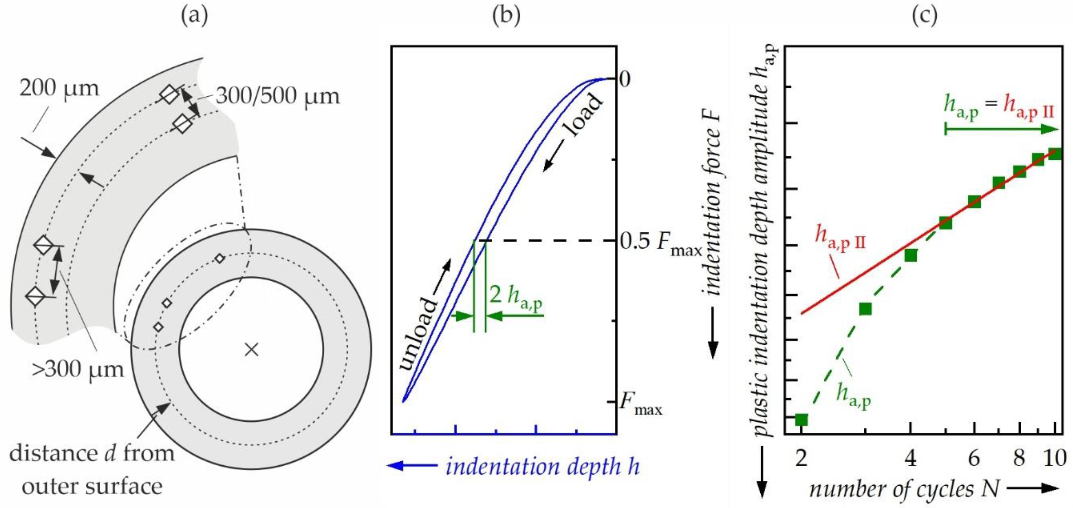
2. Materials and Methods
- Solution annealing at 540 °C for 20 min,
- Quenching in water, maximum 2-min holding time until the onset of artificial aging,
- Artificial aging at 180 °C for 4 h.
3. Results
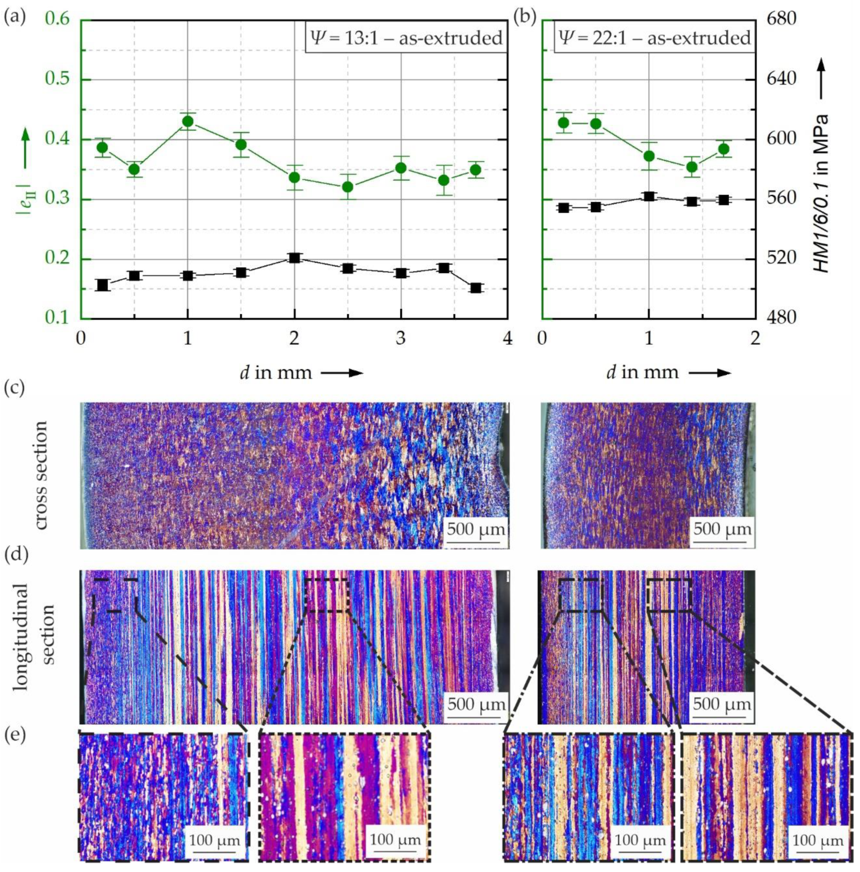
3.1. Influence of Extrusion Ratio on Hardness and Cyclic Hardening Potential
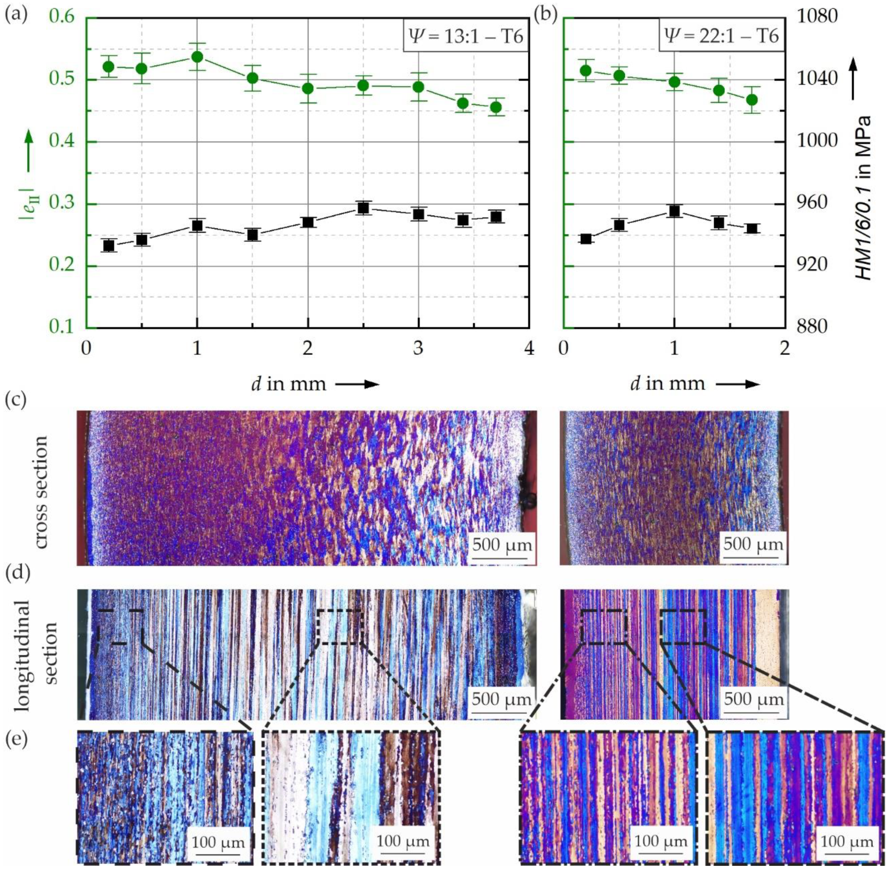
3.2. Influence of Heat Treatment on Hardness and Cyclic Hardening Potential
4. Discussion
5. Conclusions
- Hardness and cyclic hardening potential varied within the cross section for both the as-extruded and the T6 heat-treated states. This can be associated with differences in microstructure.
- In the as-extruded state, increasing the extrusion ratio from 13:1 to 22:1 led to an increase of hardness and decrease of cyclic plasticity, which nearly disappeared when applying a subsequent T6 heat treatment.
- A T6 heat treatment increased the hardness and the cyclic hardening potential and led to a decrease of cyclic plasticity obtained in CITs.
- The resulting mechanical properties cannot be explained solely based on local grain morphology, as other influencing factors such as dislocation density or precipitation state are assumed to have a significant impact as well.
- It was shown that CITs can be used to determine the local cyclic properties of extruded Al alloy tubes.
Author Contributions
Funding
Institutional Review Board Statement
Informed Consent Statement
Data Availability Statement
Conflicts of Interest
References
- Miller, W.; Zhuang, L.; Bottema, J.; Wittebrood, A.; de Smet, P.; Haszler, A.; Vieregge, A. Recent development in aluminium alloys for the automotive industry. Mater. Sci. Eng. A 2000, 280, 37–49. [Google Scholar] [CrossRef]
- Abramowicz, W. Thin-walled structures as impact energy absorbers. Thin Wall. Struct. 2003, 41, 91–107. [Google Scholar] [CrossRef]
- Alavi Nia, A.; Haddad Hamedani, J. Comparative analysis of energy absorption and deformations of thin walled tubes with various section geometries. Thin Wall. Struct. 2010, 48, 946–954. [Google Scholar] [CrossRef]
- Nowak, M.; Golovko, O.; Nürnberger, F.; Frolov, I.; Schaper, M. Water-Air Spray Cooling of Extruded Profiles: Process Integrated Heat Treatment of the Alloy EN AW-6082. J. Mater. Eng. Perform. 2013, 22, 2580–2587. [Google Scholar] [CrossRef]
- Sakai, T.; Belyakov, A.; Kaibyshev, R.; Miura, H.; Jonas, J.J. Dynamic and post-dynamic recrystallization under hot, cold and severe plastic deformation conditions. Prog. Mater. Sci. 2014, 60, 130–207. [Google Scholar] [CrossRef]
- Merriman, C.C.; Field, D.P.; Trivedi, P. Orientation dependence of dislocation structure evolution during cold rolling of aluminum. Mater. Sci. Eng. A 2008, 494, 28–35. [Google Scholar] [CrossRef]
- Zhou, W.; Yu, J.; Lin, J.; Dean, T.A. Manufacturing a curved profile with fine grains and high strength by differential velocity side-ways extrusion. Int. J. Mach. Tools Manuf. 2019, 140, 77–88. [Google Scholar] [CrossRef]
- Rollett, A.D.; Rohrer, G.S. Recrystallization and Related Annealing Phenomena, 3rd ed.; Elsevier: Amsterdam, The Netherlands, 2017; ISBN 9780080982694. [Google Scholar]
- Negendank, M.; Taparli, U.A.; Gall, S.; Müller, S.; Reimers, W. Microstructural evolution of indirectly extruded seamless 6xxx alu-minum tubes with axial variable wall thickness. J. Mater. Process. Technol. 2016, 230, 187–197. [Google Scholar] [CrossRef]
- Ostermann, F. Anwendungstechnologie Aluminium, 2nd ed.; Springer: Berlin/Heidelberg, Germany, 2007; ISBN 9783540238829. [Google Scholar]
- Hallberg, H. Approaches to Modeling of Recrystallization. Metals 2011, 1, 16–48. [Google Scholar] [CrossRef]
- Liu, M.; Lin, J.; Lu, C.; Tieu, K.; Zhou, K.; Koseki, T. Progress in Indentation Study of Materials via Both Experimental and Numeri-cal Methods. Crystals 2017, 7, 258. [Google Scholar] [CrossRef]
- Hay, J.L.; Pharr, G.M. Instrumented Indentation Testing. In Mechanical Testing and Evaluation, 11th ed.; Kuhn, H., Ed.; ASM International: Materials Park, OH, USA, 2000; pp. 231–242. ISBN 0871703890. [Google Scholar]
- Oliver, W.; Pharr, G. Measurement of hardness and elastic modulus by instrumented indentation: Advances in understanding and refinements to methodology. J. Mater. Res. 2004, 19, 3–20. [Google Scholar] [CrossRef]
- Kramer, H.S.; Starke, P.; Klein, M.; Eifler, D. Cyclic hardness test PHYBALCHT—Short-time procedure to evaluate fatigue properties of metallic materials. Int. J. Fatigue 2014, 63, 78–84. [Google Scholar] [CrossRef]
- Saraswati, T.; Sritharan, T.; Mhaisalkar, S.; Breach, C.D.; Wulff, F. Cyclic loading as an extended nanoindentation technique. Mater. Sci. Eng. A 2006, 423, 14–18. [Google Scholar] [CrossRef]
- Xu, B.; Yue, Z.; Chen, X. An indentation fatigue depth propagation law. Scr. Mater. 2009, 60, 854–857. [Google Scholar] [CrossRef]
- Görzen, D.; Schwich, H.; Blinn, B.; Bleck, W.; Beck, T. Influence of different precipitation states of Cu on the quasi-static and cyclic deformation behavior of Cu alloyed steels with different carbon contents. Int. J. Fatigue 2020, 136, 105587. [Google Scholar] [CrossRef]
- Blinn, B.; Görzen, D.; Klein, M.; Eifler, D.; Beck, T. PhyBaLCHT—Influence of indentation force on the results of cyclic hardness tests and investigations of comparability to uniaxial fatigue loading. Int. J. Fatigue 2019, 119, 78–88. [Google Scholar] [CrossRef]
- Lim, Y.Y.; Chaudhri, M.M. The influence of grain size on the indentation hardness of high-purity copper and aluminium. Philos. Mag. A 2002, 82, 2071–2080. [Google Scholar] [CrossRef]
- Weiler, J.P.; Wood, J.T.; Klassen, R.J.; Berkmortel, R.; Wang, G. The effect of grain size on the flow stress determined from spherical microindentation of die-cast magnesium AM60B alloy. J. Mater. Sci. 2005, 40, 5999–6005. [Google Scholar] [CrossRef]
- Cordero, Z.C.; Knight, B.E.; Schuh, C.A. Six decades of the Hall–Petch effect—A survey of grain-size strengthening studies on pure metals. Int. Mater. Rev. 2016, 61, 495–512. [Google Scholar] [CrossRef]
- Hall, E.O. The Deformation and Ageing of Mild Steel: III Discussion of Results. Proc. Phys. Soc. B 1951, 64, 747–753. [Google Scholar] [CrossRef]
- Schwich, H.; Görzen, D.; Blinn, B.; Beck, T.; Bleck, W. Characterization of the precipitation behavior and resulting mechanical prop-erties of copper-alloyed ferritic steel. Mater. Sci. Eng. A 2020, 772, 138807. [Google Scholar] [CrossRef]
- Klein, M.W.; Blinn, B.; Smaga, M.; Beck, T. High cycle fatigue behavior of high-Mn TWIP steel with different surface morphologies. Int. J. Fatigue 2020, 134, 105499. [Google Scholar] [CrossRef]
- Blinn, B.; Görzen, D.; Fischer, T.; Kuhn, B.; Beck, T. Analysis of the Thermomechanical Fatigue Behavior of Fully Ferritic High Chromium Steel Crofer®22 H with Cyclic Indentation Testing. Appl. Sci. 2020, 10, 6461. [Google Scholar] [CrossRef]
- Edwards, G.A.; Stiller, K.; Dunlop, G.L.; Couper, M.J. The precipitation sequence in Al–Mg–Si alloys. Acta Mater. 1998, 46, 3893–3904. [Google Scholar] [CrossRef]
- Perovic, A.; Perovic, D.; Weatherly, G.; Lloyd, D. Precipitation in aluminum alloys AA6111 and AA6016. Scr. Mater. 1999, 41, 703–708. [Google Scholar] [CrossRef]
- Aginagalde, A.; Gomez, X.; Galdos, L.; García, C. Heat Treatment Selection and Forming Strategies for 6082 Aluminum Alloy. J. Eng. Mater. Technol. 2009, 131. [Google Scholar] [CrossRef]
- Maisonnette, D.; Suery, M.; Nelias, D.; Chaudet, P.; Epicier, T. Effects of heat treatments on the microstructure and mechanical prop-erties of a 6061 aluminium alloy. Mater. Sci. Eng. A 2011, 528, 2718–2724. [Google Scholar] [CrossRef]


| Element | Si | Mg | Mn | Fe | Cu | Cr | Al |
|---|---|---|---|---|---|---|---|
| Content | 0.82 | 0.98 | 0.55 | 0.27 | 0.07 | 0.07 | 97.10 |
Publisher’s Note: MDPI stays neutral with regard to jurisdictional claims in published maps and institutional affiliations. |
© 2021 by the authors. Licensee MDPI, Basel, Switzerland. This article is an open access article distributed under the terms and conditions of the Creative Commons Attribution (CC BY) license (https://creativecommons.org/licenses/by/4.0/).
Share and Cite
Görzen, D.; Schäfke, F.P.; Blinn, B.; Klose, C.; Maier, H.J.; Beck, T. Investigating the Influence of Process Parameters on the Mechanical Properties of Extruded Aluminum Tubes by Cyclic Indentation Tests. Metals 2021, 11, 744. https://doi.org/10.3390/met11050744
Görzen D, Schäfke FP, Blinn B, Klose C, Maier HJ, Beck T. Investigating the Influence of Process Parameters on the Mechanical Properties of Extruded Aluminum Tubes by Cyclic Indentation Tests. Metals. 2021; 11(5):744. https://doi.org/10.3390/met11050744
Chicago/Turabian StyleGörzen, David, Florian Patrick Schäfke, Bastian Blinn, Christian Klose, Hans Jürgen Maier, and Tilmann Beck. 2021. "Investigating the Influence of Process Parameters on the Mechanical Properties of Extruded Aluminum Tubes by Cyclic Indentation Tests" Metals 11, no. 5: 744. https://doi.org/10.3390/met11050744
APA StyleGörzen, D., Schäfke, F. P., Blinn, B., Klose, C., Maier, H. J., & Beck, T. (2021). Investigating the Influence of Process Parameters on the Mechanical Properties of Extruded Aluminum Tubes by Cyclic Indentation Tests. Metals, 11(5), 744. https://doi.org/10.3390/met11050744