Article

Comparative Study of the Properties of Cu-Cr-Mo System Electrical Contact Material by Sintering and Infiltration Methods

1
Korea Institute for Rare Metals, Korea Institute of Industrial Technology, Incheon 21999, Korea
2
Department of Advanced Materials Engineering, In-Ha University, Incheon 22212, Korea
3
VITZRO EM Co., Ltd., Ansan 15616, Korea
*
Authors to whom correspondence should be addressed.
Metals 2021, 11(5), 700; https://doi.org/10.3390/met11050700
Submission received: 2 April 2021 / Revised: 16 April 2021 / Accepted: 20 April 2021 / Published: 25 April 2021
(This article belongs to the Section Powder Metallurgy)

Abstract

:
Contact materials in high-voltage vacuum interrupters require properties such as high conductivity, density and hardness to minimize arc heat damage. In this study, Cu–Cr–Mo alloy contact materials were examined for their usage as high-voltage contact materials. Ball milling was performed after analyzing the raw materials of the Cu, Cr and Mo powders. A green compact was produced using high pressure with a mixed powder. Subsequently, the composite was produced by sintering via the temperature and infiltration method according to the Cu content in the green compact. The composite sintering method produced a density of 8.55 g/cm3 (relative density 93%), a hardness of 217 HV and an electrical conductivity of 40.7% IACS at 1200 °C. The composite of 10 wt.% Cu produced by the Cu infiltration method exhibited a density of 8.7 g/cm3 (relative density 94%), hardness of 274 HV and electrical conductivity of 39 IACS% at 1300 °C. The measurements of the physical properties of our newly established method demonstrated a new possibility of using the Cu–Cr–Mo alloy as a contact material for high-voltage vacuum interrupters.

Graphical Abstract

1. Introduction

Insulation and arc extinction properties are essential for contact materials used in high-voltage vacuum interrupters during contact operations and the mechanical properties of the electrical contact materials are crucial for meeting their requirements. If an arc occurs during the on/off operation of the electrical contact point, the arc heat causes local melting of the material surface, resulting in damage and breakage at the contact point. As materials require thermal and electrical conductivity, high hardness and high density to avoid damage from arc heat, two or more materials must be combined. Copper-chromium (Cu–Cr)-based contact materials with a chromium content between 15 and 50 wt.% are widely used in vacuum interrupters for medium voltage applications. However, inadequate research has been focused on developing contact materials for high-voltage vacuum interrupters [1,2,3].
Cu is a critical material in power devices owing to its outstanding thermal and electrical conductivity, corrosion resistance and excellent machinability. However, Cu has low hardness and limited industrial applications because of the segregation that occurs during solidification. The hardness of Cu could be increased by adding an alloy element; however, this might reduce its conductivity. Therefore, to maintain high conductivity, Cu and insoluble alloying elements should be added. Cr and Mo can be fabricated into stable alloys in the Cu matrix. This is because Cr and Mo are homogeneous solid solutions with a BCC crystal structure, same number of valence electrons and similar chemical properties. If mixed in any ratio, Cr–Mo exists as a single phase, even at high temperatures. Cu–Cr–Mo has no pure thermodynamic driving forces for this alloy to form a solid solution or an amorphous phase because the Gibbs free energy change is positive. Thus, to fabricate a uniform Cr–Mo phase, the additional energy provided by the mechanical alloy is required. The high melting point of Mo and the fine Cr-Mo phase in the Cu-matrix interface have high hardness, fracture toughness, corrosion resistance and abrasion resistance. Therefore, they can be applied in high-voltage vacuum interrupters [4,5,6,7].
The widely used manufacturing methods of contact materials such as the Cu–Cr and Cu–W systems include melting, infiltration, laser irradiation and sintering. During melting or laser irradiation process, all metals are melted in vacuum. However, a large difference in the melting point between metals can potentially result in a non-uniform structure during the solidification process, although they turn into a uniform liquid phase. Hence, it is technically challenging to obtain a uniform dispersion of metals using the laser melting method [8,9,10,11,12,13].
Therefore, in this study, we produced a green compact by mixing raw materials and pressurizing them to produce Cu–Cr–Mo system contact materials. Next, we compared a composite fabricated by liquid-phase sintering of a Cu–Cr–Mo mixture and a composite made by the infiltration of Cu into the Cr–Mo–Cu green compact body. The X-ray and microstructure of the composite materials and their important mechanical properties, including electrical conductivity, hardness and density, were analyzed. Furthermore, to check the applicability of the high-voltage vacuum interrupter, a short-circuit test was performed by connecting the manufactured composite material.

2. Materials and Methods

2.1. Materials

Figure 1 shows scanning electron microscopy (SEM) images of the raw materials of Cu (Avention Co. Ltd., Incheon, Korea, 99.9% purity, 28 µm average particle size), Cr (Avention Co. Ltd., Incheon, Korea, 99.9% purity, 27 µm average particle size) and Mo (Avention Co. Ltd., Incheon, Korea, 99.9% purity, 20 µm average particle size) composite powders generated by sintering and infiltration.

2.2. Experimental Process

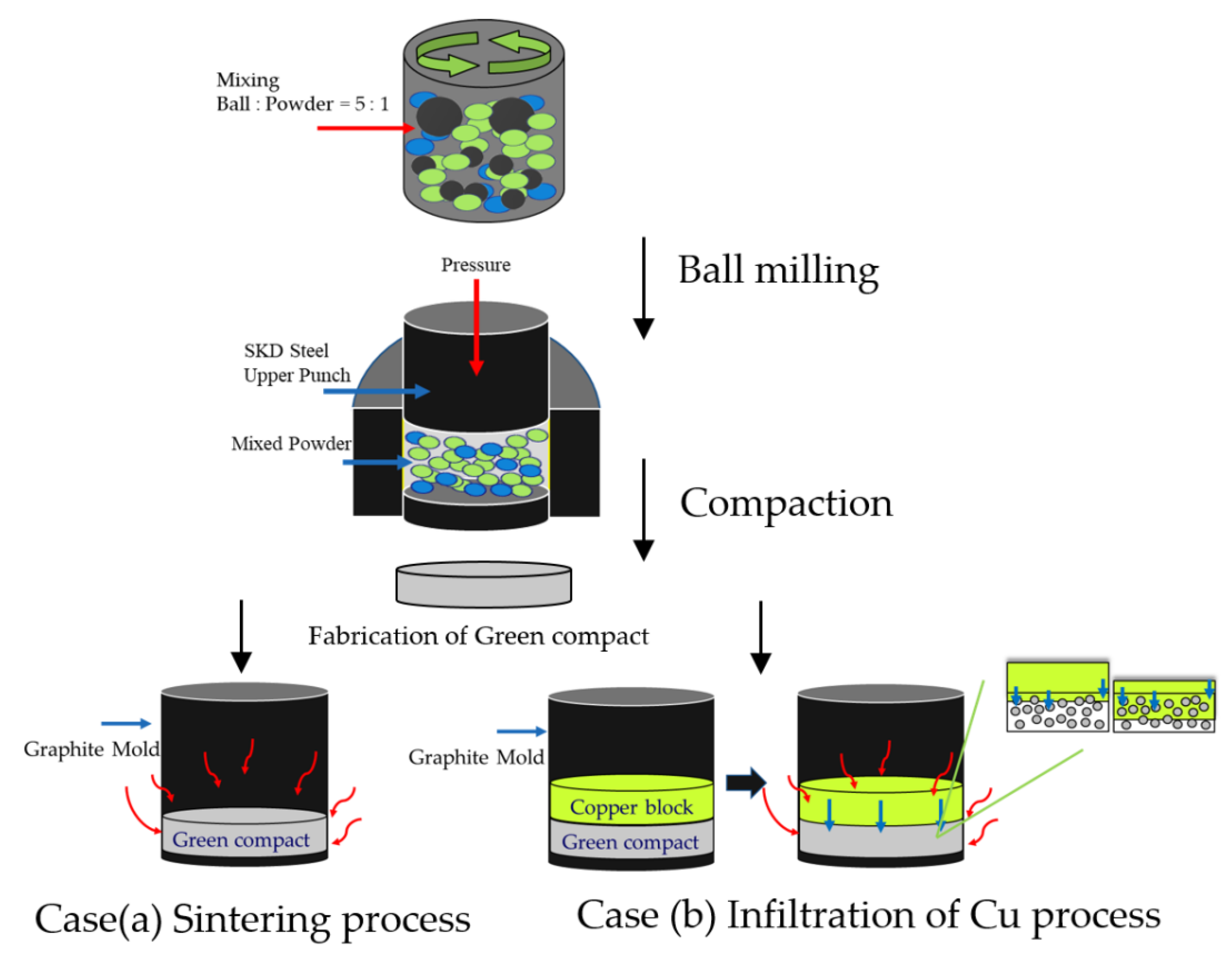
The sintering process (case (a)) of the composite is shown in Figure 2a. For powder preparation, 60 wt.% Cu–30 wt.% Mo–10 wt.% Cr were mixed and milled in a commercial planetary ball mill. Tungsten carbide balls (diameter 10 mm and 5 mm) were used as the milling media. Mixing was performed at 200 rpm for 4 h in air with a ball-to-powder weight ratio (BPR) of 5:1. Subsequently, the mixed powder was loaded into a steel mold and pressurized at 148.5 MPa for 210 s to produce an 82 mm diameter green compact. The green compact was then transferred into an alumina crucible and heated at a rate of 10 °C/min, maintained at 1100 °C and 1200 °C for 3 h under an Ar atmosphere.
The infiltration method (case (b)) of Cu into the Cr–Mo–Cu green compact is shown in Figure 2b. The ball mill mixture and green compact were produced under the same conditions as the sintering process after mixing 10 wt.% Cr–30 wt.% Mo–10 wt.% Cu (50 wt.% Cu block) and 10 wt.% Cr–30 wt.% Mo–30 wt.% Cu (30 wt.% Cu block) powders. Next, to fill the remaining Cu content, Cu blocks (99.9% purity, 82 mm diameter) were placed on top of the green compact and then placed inside a graphite mold (82 mm inner diameter). The infiltration process was performed for 3 h at 1300 °C under an Ar atmosphere at a heating rate of 8 °C/min in atmospheric pressure.

2.3. Analysis Technique

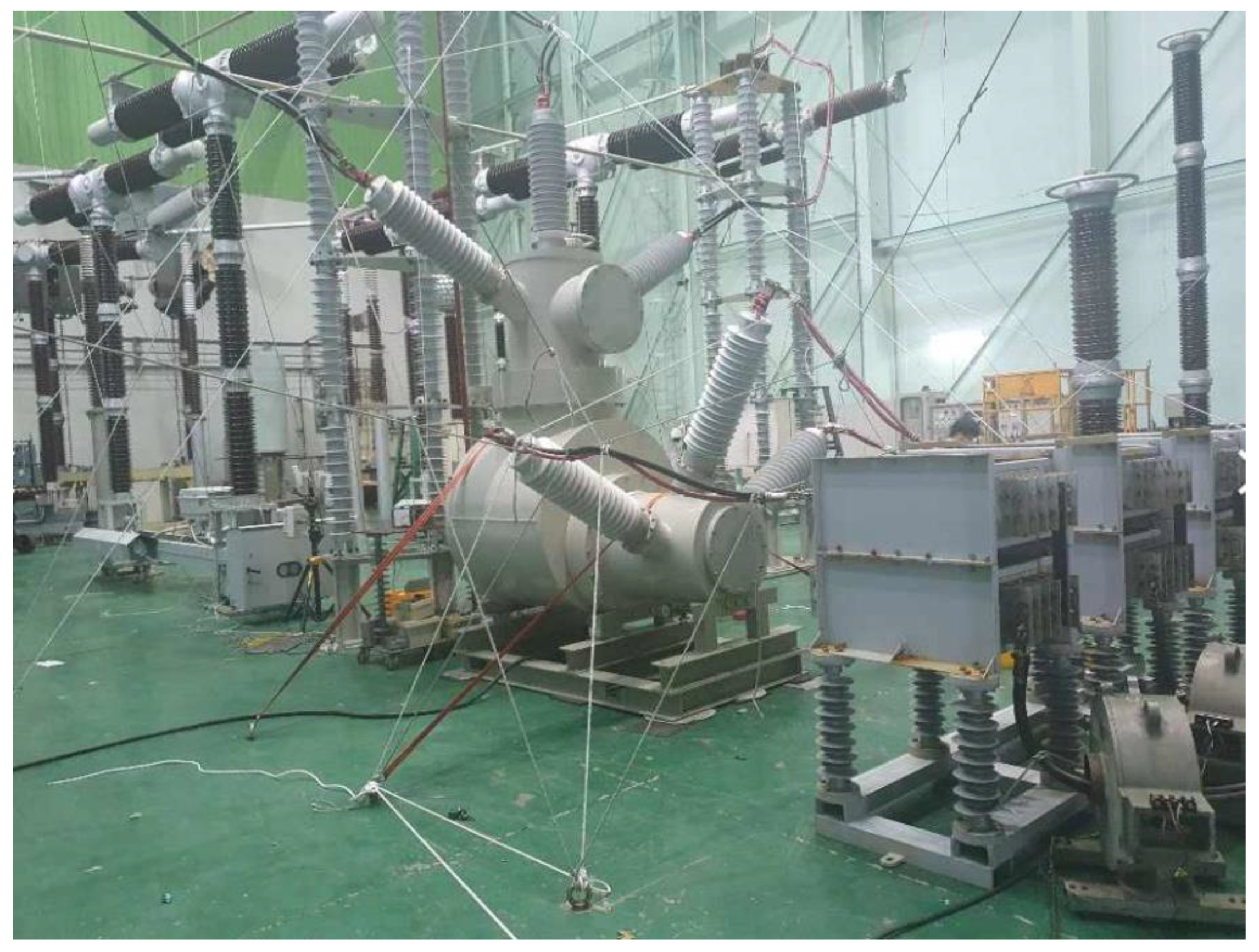
Archimedes’ principle is widely used to measure the solid density and porosity of powder metallurgy composites. The relative density of a part is closely related to the existence of internal pores in it. The bulk density of composites fabricated by sintering and infiltration processes was measured by Archimedes’ method according to ASTM-B962 standard. In addition, the relative density was calculated from theoretical density and bulk density [14]. Hardness was measured by Vickers hardness tester (Mitutoyo, HM210A, Seoul, Korea) by applying a load of 0.1 kgf for 10 s. Electrical conductivity was analyzed by passing eddy current across a cross-section using an electric conductivity meter (SIGMASCOPE, SMP350, Sidelfingen, Germany) and %IACS (International Annealed Copper Standard) was calculated. The microstructure and crystal structure of the composites were observed using scanning electron microscopy/energy dispersive X-ray spectroscopy (SEM/EDS, JEOL, JSM-7100F, Tokyo, Japan) and X-ray diffraction (XRD, BRUKER AXS, D8 ADVANCE, Hanau, Germany) after mechanical polishing of the composite surface. A short-circuit test was performed to confirm whether the vacuum interrupter based on the manufactured composite could break the 72.5 kV 40 kA rating. Figure 3 shows the connecting cable for the short-circuit test. These conditions were selected in accordance with the IEC 62271-100. The first-pole clear factor (Kpp) was 1.5, the amplification factor (Kaf) was 1.4 and the transient recovery voltage (TRV, Uc) was 124 kV. T100s(b) and T100a are short-circuit tests which break 100% of the test current; they were repeated 11 and 2 times, respectively.

3. Results and Discussion

3.1. Materials

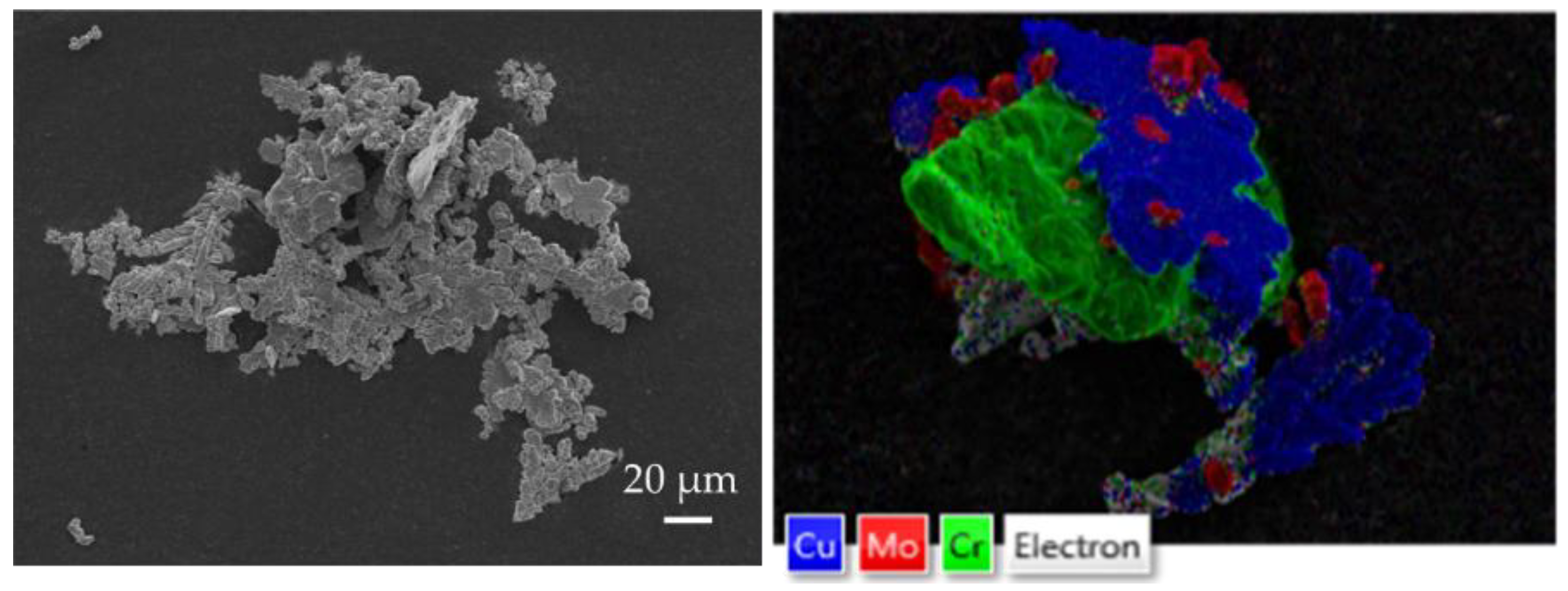
Figure 4 shows SEM/EDS images of Cu, Cr and Mo material powders mixed by ball milling. The SEM/EDS analysis revealed that the powders were mechanically alloyed and the shape of the Cu particle changed from coral to plate because of ball milling as Cu has higher ductility than Mo and Cr. Mo particle diameter was separated to less than 5 µm. In numerous studies on milling, the mixing time was crucial and increasing the mixing time resulted in more homogeneous particles and stability and refinement of materials during post-processing [15,16].

3.2. Shrinkage

Photographs of the macroscopic features of the composites produced by sintering and Cu infiltration are shown in Figure 5. The heat treatment temperature was varied for both methods because the Cu that emerged from the green compact was out of shape when the sintering temperature was set at 1300 °C. Therefore, the sintering temperature was set to 1100–1200 °C, given the fluidity of Cu in the liquid phase and the infiltration temperature was set to 1300 °C. The diameters of the four produced composites decreased after the heat treatment process. This happened because after sintering the composites at a temperature higher than the melting point of Cu and subsequent cooling, the Cu, which was dispersed between the pores of the green compact in its liquid phase, changed into its solid phase and underwent solidification shrinkage owing to the attraction of the particles. Furthermore, the composite contracted horizontally because it received more vertical pressure than the horizontal pressure during the green compact fabrication process [17]. Based on the shrinkage ratio analysis, the 1200 °C sample generated by the sintering method had the largest diameter shrinkage ratio of approximately 9%, followed by the composite at 1300 °C 30 wt.% Cu, composite of 1100 °C and composite of 1300 °C 10 wt.% Cu, as shown in Table 1.

3.3. Sintering (Case (a))

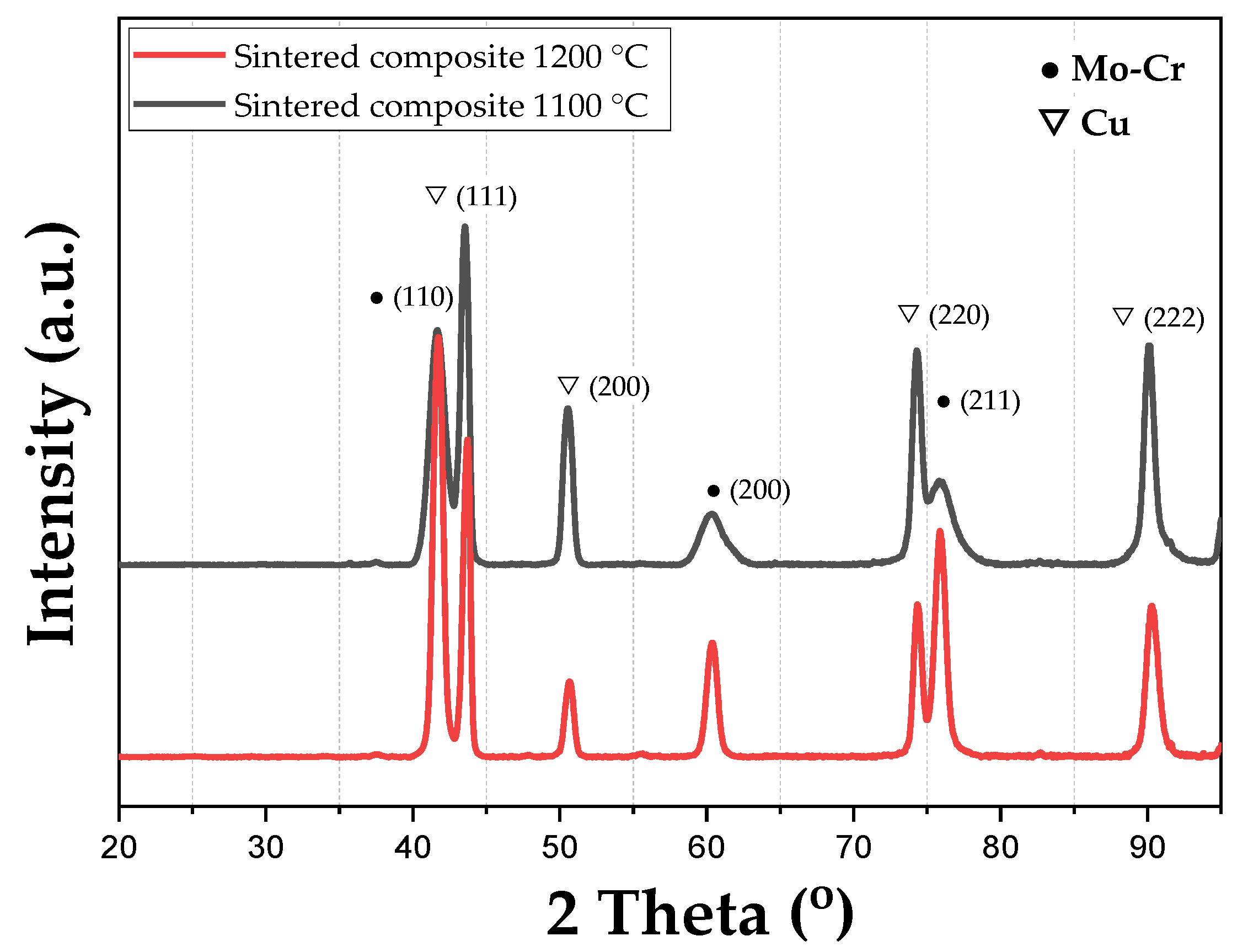
The alloying and crystal structure of the composite produced by the sintering method were investigated using XRD. Figure 6 shows the XRD patterns of the composite produced at 1100 °C and 1200 °C according to the temperature obtained by liquid sintering. The diffraction peaks correspond to the Cu and the Mo–Cr phases. The composite sintered at 1100 °C (sample no. 1) had a lower diffraction intensity of the Mo–Cr phase than the composite sintered at 1200 °C (sample no. 2). Because the temperature was low, sintering between the Mo-Cr interface was not sufficiently performed; the intensity was low and the full width at half maximum (FWHM) was broad.
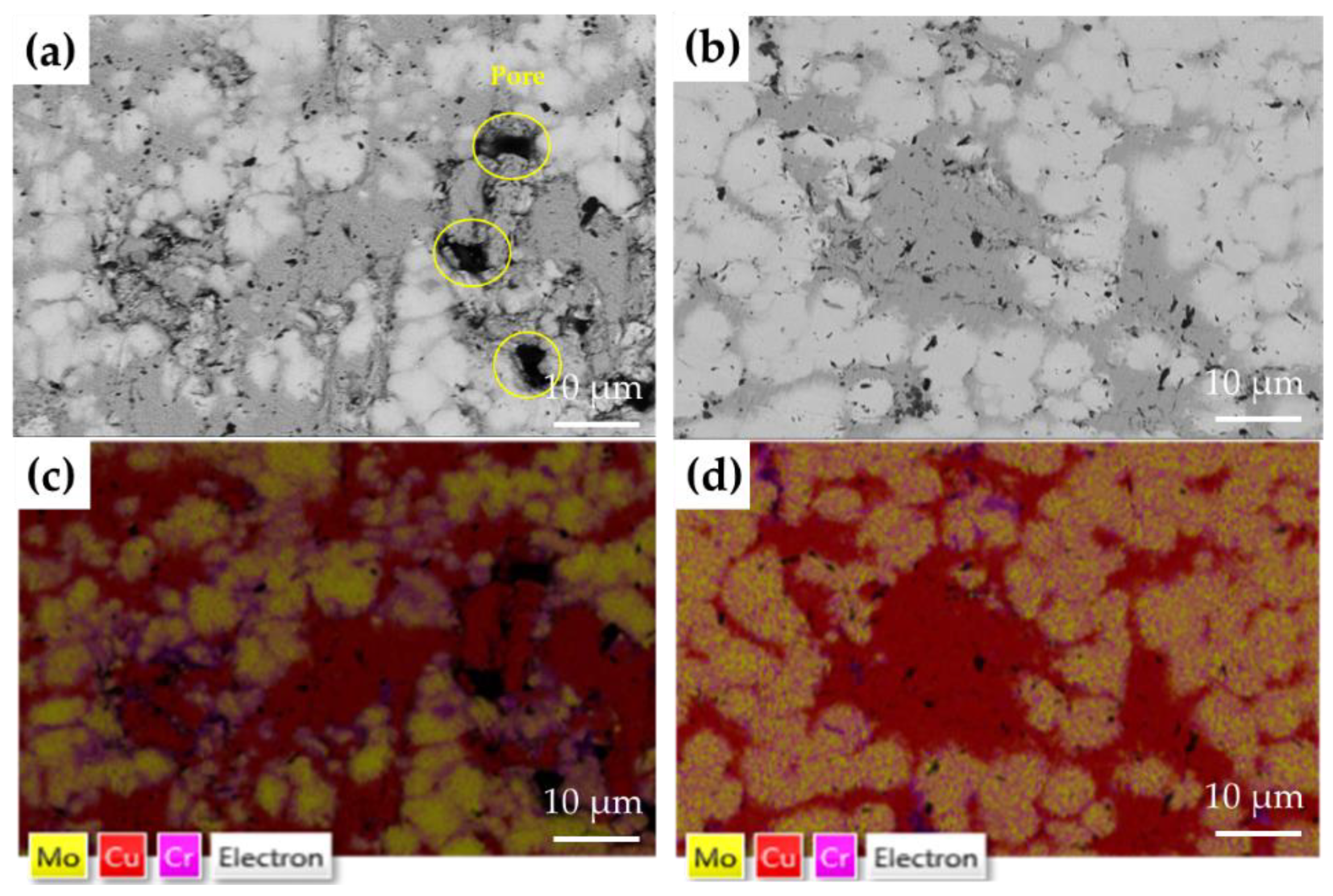
Figure 7 shows the SEM/EDS images of the microstructures of the 60 wt.% Cu–10 wt.% Cr–10 wt.% Mo composite produced by the sintering method. When the microstructure of the 1100 °C composite was examined, large pores were observed. There was insufficient Cu in the high-viscosity liquid at 1100 °C and, as a result, the unstable flow of the copper melt resulted in segregation. In contrast, it was found that in the microstructure of the 1200 °C composite, Cu, Cr and Mo were uniformly distributed with no large pores and insignificant segregation [17,18,19,20].
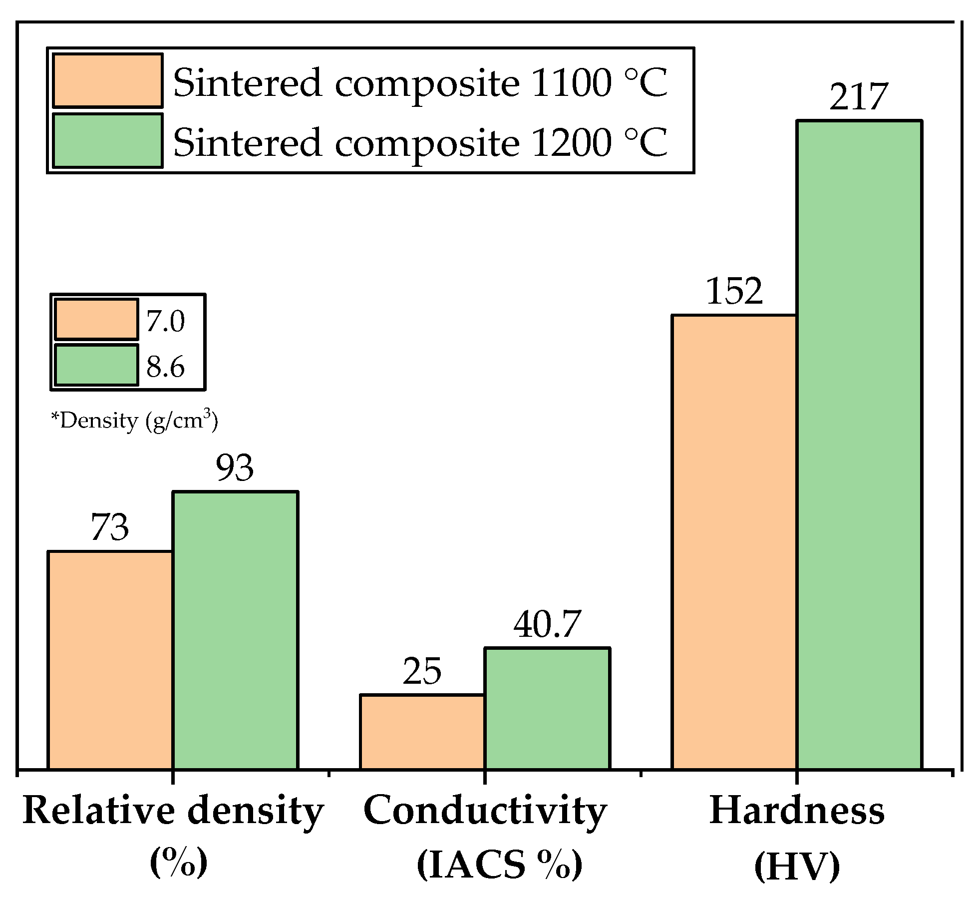
Figure 8 shows the density, conductivity and hardness of the composites produced by the sintering method. The composite maintained at a sintering temperature of 1100 °C for 3 h exhibited a density of 7.0 g/cm3 (relative density: 73%), an electrical conductivity of 25%IACS and a hardness of 152 HV (sample no. 1). The composite maintained at a sintering temperature of 1200 °C for 3 h exhibited a density of 8.55 g/cm3 (relative density: 93%), a conductivity of 40.7% IACS and a hardness of 217 HV (sample no. 2), thus demonstrating better properties. This is because, although the melting point of Cu is 1083 °C, the Cu phase is not sufficiently liquidized at 1100 °C, resulting in an unstable bulk body and many pores. Furthermore, impurities present in the powder, including organic phases, evaporate at high temperatures, creating expansion and pore formation. When the sintering temperature was gradually increased, Cu was fully melted and the viscosity of liquid Cu decreased, which further promoted the rearrangement of the Cr–Mo particles. This implies that high temperatures contribute significantly in improving the degree of densification [21,22,23,24].
The formation of pores reduces the density and because the Cu network is not properly distributed around the pores, electron movement in the Cu is obstructed, thus negatively affecting conductivity. The electrical resistance increased rapidly when the actual pore size increased; however, it was negligibly affected by the pore size when the pore size was sufficiently small [25,26]. Thus, when the temperature is 1200 °C instead of 1100 °C, the conductivity is higher owing to the uniform distribution of Cu and the small number of pores with a smaller size.
If a composite material, with a composition identical to the one used in this study, is sintered at a temperature higher than 1100 °C, then it achieves a higher density and hardness [18]. According to the Hall–Petch effect, the larger the grain size of the composite, the lower the hardness value. However, we saw no significant difference in the sizes of the Cr–Mo particles in the composite microstructure. Hardness is correlated with density and pores cause stress condensation and low density. Thus, the temperature for densification of sintering is advantageous at 1200 °C rather than at 1100 °C. The homogeneous microstructure of composites sintered at higher temperatures leads to superior physical properties [27].

3.4. Infiltration (Case (b))

The infiltration method requires a green compact to have a low density because its efficiency depends on the pore volume. However, although pore volume is important, adequate pressurization is essential because maintaining the shape of the green compact is critical. In this study, the green compact was pressurized at 148.5 MPa and the shape could not be maintained if it was pressurized at a lower pressure. In addition, the Cr–Mo green compact without Cu did not maintain its shape.
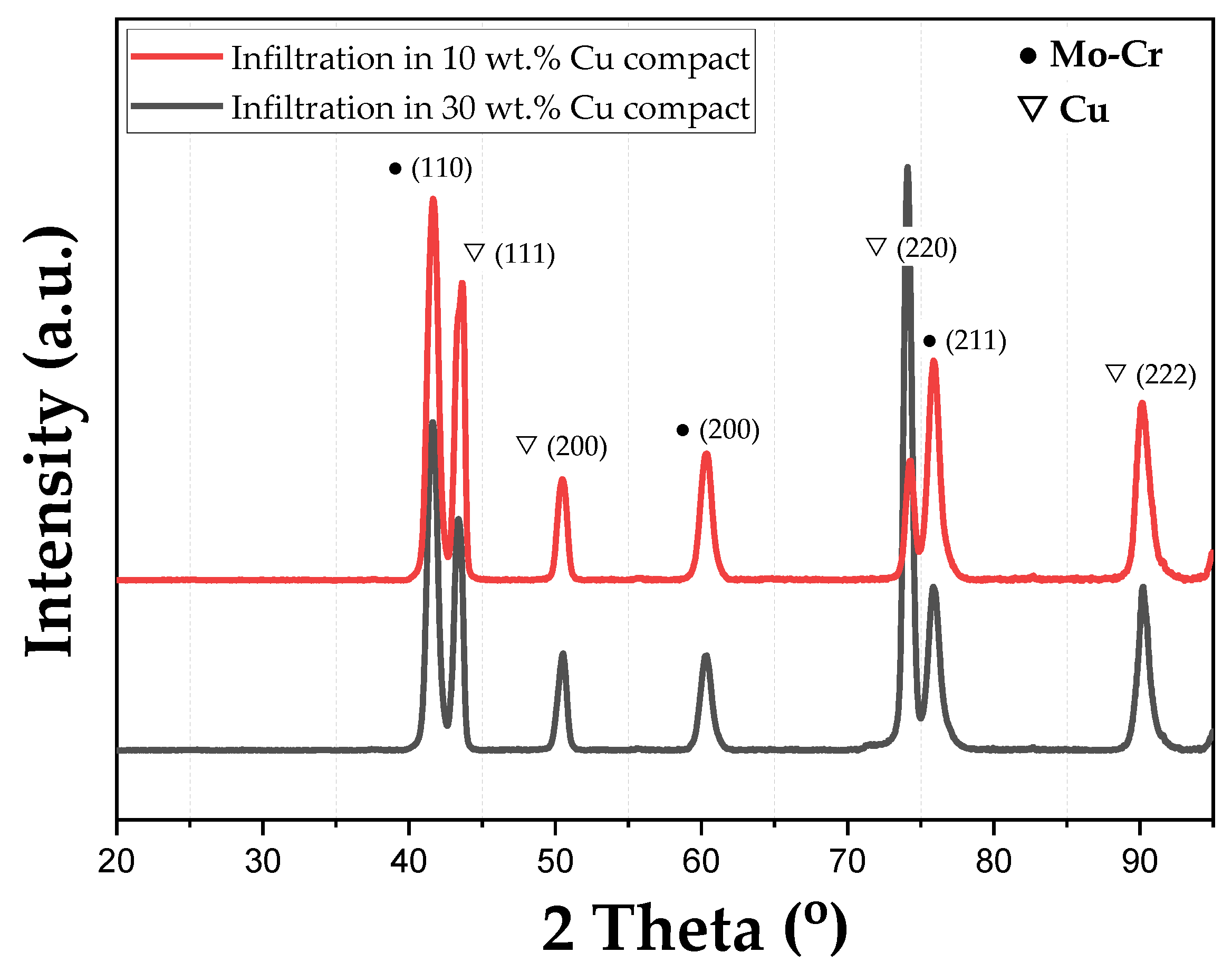
The XRD pattern of the composite produced by infiltrating the Cu bulk in a green compact with a Cu content of 10 wt.% Cu composite (sample no. 3) and 30 wt.% Cu composite (sample no. 4) is shown in Figure 9. The diffraction peaks correspond to the Cu and the Mo–Cr phases. Neither composite showed peaks for the other compounds. The intensities of the Cu peak (220) at 74.14 showed that sample no. 4 contained a higher Cu content than sample no. 3.
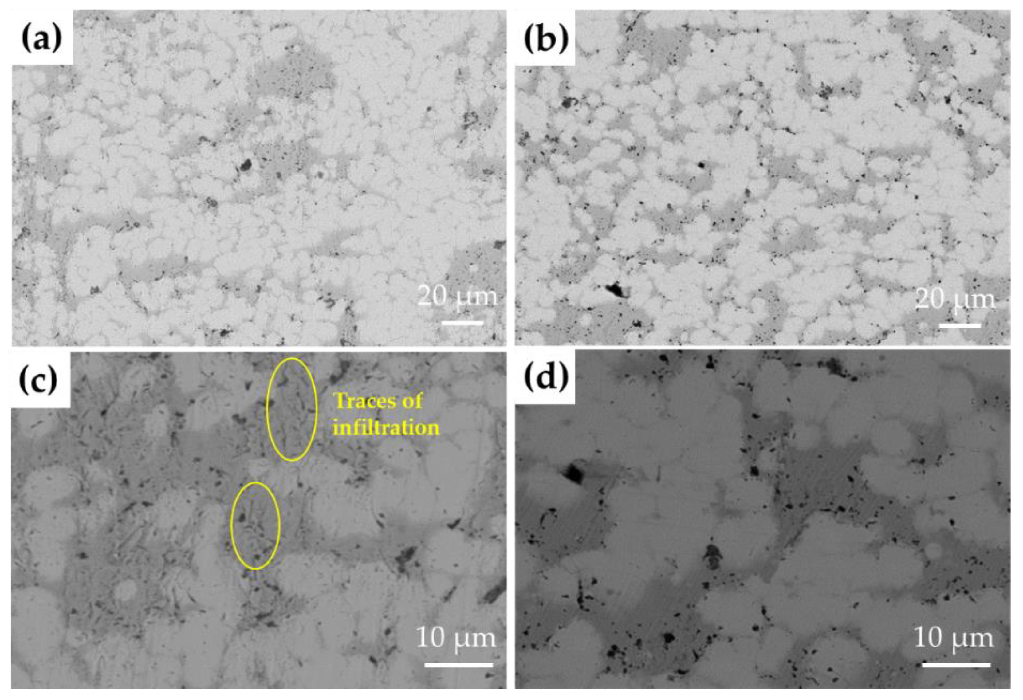
Figure 10 shows SEM images of the microstructure of 10 wt.% Cu and 30 wt.% Cu composites produced by the infiltration method. The dark gray represents the Cu area and the bright gray represents the Cr–Mo area. Traces of infiltration can be found in the microstructure of 10 wt.% Cu and the distribution of some Cu is non-uniform. The microstructure of 30 wt.% Cu composites has a relatively uniform distribution of Cu, but a higher number of pores. The uniform distribution and high content of Cu can improve the conductivity, but the pores reduce the density [11].
Figure 11 shows the density, electrical conductivity and hardness of the composites generated by the infiltration method. The 10 wt.% Cu composite maintained at a sintering temperature of 1300 °C for 3 h exhibited a density of 8.7 g/cm3 (relative density 94%). The 30 wt.% Cu composite exhibited a density of 8.2 g/cm3 (relative density 89%). The 10 wt.% Cu composite had a slightly higher density than that of the 30 wt.% Cu composite. This suggests that the open pores in the green compacts of the sample with 10 wt.% Cu were more secure than those of the 30 wt.% Cu sample. Moreover, for the 30 wt.% Cu composite, it was observed that some Cu flowed out after the experiment ended. This is attributed to the Cu content in the green compact flowing out because of pressure from the Cu block. This is a phenomenon caused by high Cu content, resulting in a higher escape rate than the infiltration rate during the liquid phase sintering process. Large pores in sample. no. 4, as observed in the SEM image, are also assumed to be the result of this phenomenon, resulting in a low relative density of sample no. 4 [21,22,23,24,25,26]. Thus, the 10 wt.% Cu composite achieved higher relative density because the pore size was significantly lower.
The sintered composite from the green compacts with a 10 wt.% of Cu exhibited lower electrical conductivity than that with 30 wt.% Cu. The 30 wt.% Cu composite (sample no. 4) exhibited higher electrical conductivity. This is because the electrical conductivity depends on the Cu content and its distribution. The 30 wt.% Cu green compact has a higher Cu content between Mo–Cr contacts than the 10 wt.% Cu green compact. Thus, an electrical conductivity of 30 wt.% Cu composite (sample no. 4), which is uniformly distributed after Cu infiltration, was found to be higher despite the larger pore size [22,23,24,25,26,27].
In the case of the hardness of the composite, it is expected that the Mo–Cr compositional ratio in the green compacts is more predominant because the ratio of Mo–Cr in 10 wt.% Cu is relatively higher than 30 wt.% Cu in the process of fabricating the green compact. In addition, the high density of the sintered composite was the main cause of the high hardness. Therefore, the 10 wt.% Cu composite (sample no. 3) was considered to have a high hardness [24,25,26,27,28].

3.5. Short-Circuit Test

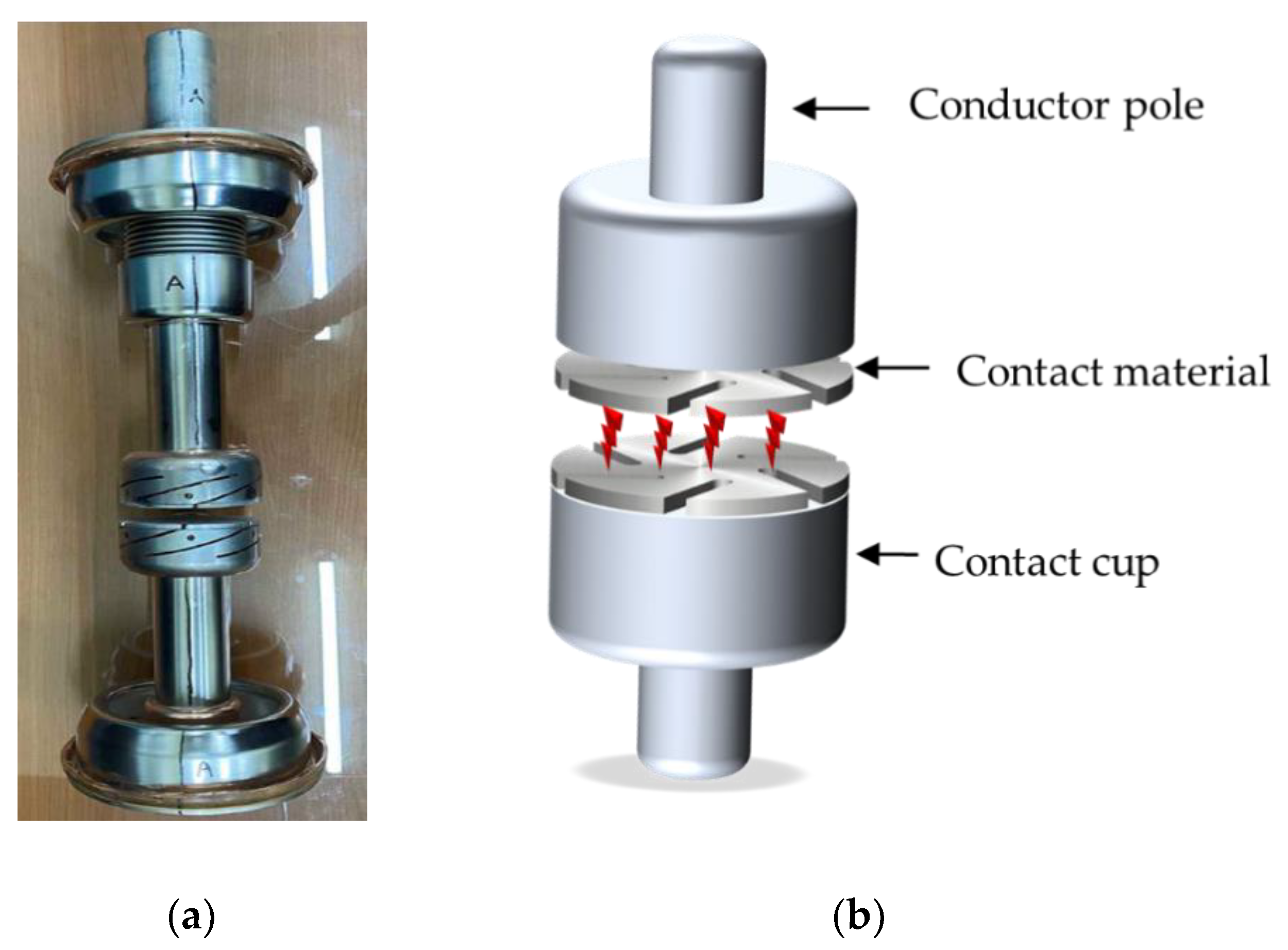
In this study, short-circuit tests were conducted using magnetic forces. An axial system creates a uniform magnetic field in a direction parallel to the arc, controlling the concentration of the arc and spreading the arc to the front of the electrode [29]. Figure 12 shows the shape of the vacuum interrupter and cup-type axial magnetic force (AMF) structure. Short-circuit testing was performed for 60 wt.% Cu–10 wt.% Cr–10 wt.% Mo composite (samples no. 2) produced by the sintering method due to its suitable balance of physical properties. The T100s(b) test is a three-phase 100% symmetric current short-circuit test and T100a is a three-phase 100% asymmetric current short-circuit test. T100a breaks the asymmetric currents containing DC current components and is the most difficult high-current test in the IEC test. For T100s(b), the C phase was the first pole. As a result of T100s(b) test while changing the arcing time, the minimum arcing time, intermediate arcing time and maximum arcing time were successfully broken at 5.8, 6.7 and 7.6 ms, respectively, and the arc window was successfully confirmed. There was some degree of consumption of the contact surface when the T100s(b) breaking test was performed more than 10 times, but the T100a test was performed without replacing the vacuum interrupter. Breakage was successful at 6.7 ms arcing time and a fair amount of breaking performance was observed [30,31].
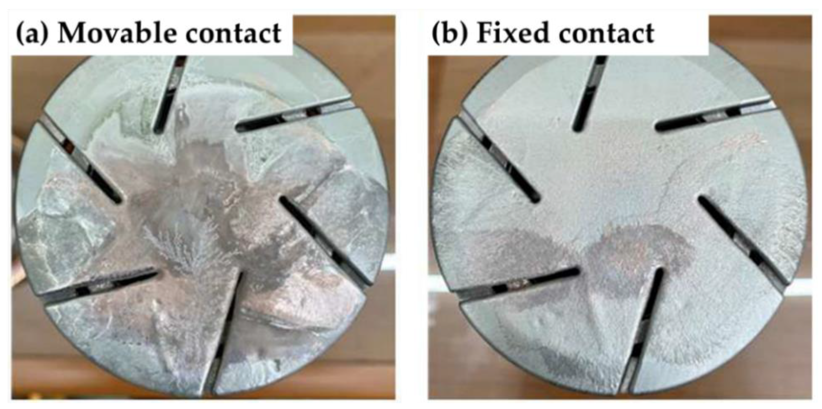
As a result of these 13 tests, a 40 kA short-circuit current was broken and the applicability of Cu–Cr–Mo (sample no. 2) as an electrical contact material in a vacuum interrupter was successfully observed. Figure 13 shows the actual Cu–Cr–Mo composite (sample no. 2) after a 40 kA breaking test. In a 72.5 kV vacuum interrupter, large power is applied to the movable part because it is located at the top and the fixed part is located at the bottom. Therefore, damage to the contact surface by the anode spot primarily occurred at the movable part. Despite the thermal shock applied during the breaking test, there were very little visible wear or cracks on the contacts [31,32,33]. Table 2 shows a comparison of the characteristics of the electrical contact material for a vacuum interrupter. The content and method of fabrication for each electrical contact material were slightly different. Comparing the properties of various contact materials, the electrical conductivity was similar and the hardness was overwhelmingly high. According to the Cu–Cr alloy in another study [34,35,36], when the chrome content is high, the ability to interrupt is gradually reduced. This results in a decrease in the copper content and electrical conductivity, thereby resulting in a decrease in the short-circuit performance even though chromium has heat and welding resistance. If the chromium content is reduced, welding of the product occurs during the operation of the interrupter and the wear resistance decreases resulting in a shortened life of the product because chromium prevents soft copper parts from being welded together [36]. In this study, the Cu content of the Cu-Cr-Mo composites was relatively lower than that of the conventional Cu-Cr composites. However, the electrical conductivity was similar to or higher than that of other materials, which shows that our manufacturing method is a successful way to fabricate a homogeneous structured Cu-Cr-Mo composite. The uniform microstructure also affects the high hardness of the Cu-Cr-Mo composite. In addition, the high Mo content significantly improves the thermal stability [37]. Therefore, even if arc heat is generated by high voltage, sample damage is minimized. As a result, it successfully passed the short-circuit test at 72.5 kV/40 kA, which is much vigorous compared to other Cu-Cr composite materials. Therefore, it can be seen that the Cu-Cr-Mo composite material can be applied to a high-voltage vacuum interrupter. Nevertheless, to optimize the conditions for the fabrication of Cu-Cr-Mo composites for high-voltage VI, further studies on the physical properties and blocking performance should be performed.

4. Conclusions

In this study, Cu–Cr–Mo system composites were produced using liquid-phase sintering and infiltration methods to develop high-voltage vacuum interrupter contact materials. The mechanical properties required for contact materials, such as density, hardness, electrical conductivity and microstructures, were compared and analyzed. As a result, the following conclusions were drawn:
  • Cu–Cr–Mo composite produced by sintering generated better mechanical properties and homogeneous structure at a sintering temperature of 1200 °C (sample no. 2) than at 1100 °C (sample no. 1).
  • In case of the Cu–Cr–Mo composite manufactured by Cu infiltration method, sample 3 (10 wt.% Cu compact) showed the high density and hardness. Some segregation was also observed due to infiltration of large amounts of Cu. Sample 4 (30 wt.% Cu compact) exhibited the high electrical conductivity. Composites produced by infiltration method had better mechanical properties than those fabricated by sintering method.
  • The measurements of mechanical properties and short-circuit tests depicted a new possibility of using the Cu–Cr–Mo composite as a contact material for high-voltage vacuum interrupters. These preliminary results necessitate further research on this topic.

Author Contributions

Y.-W.C.: Investigation, methodology, writing—original draft; J.-S.B., J.-J.S.: Investigation, Software; T.-S.K.: Resources; H.-J.J.: Validation; K.-A.L., S.-J.S.: Supervision; K.-T.P.: Funding acquisition, project administration, writing—review & editing. All authors have read and agreed to the published version of the manuscript.

Funding

This study was supported by the Korea Institute of Energy Technology Evaluation and Planning (KETEP), the Ministry of Trade, Industry & Energy (MOTIE) of the Republic of Korea (No. 20165010100870), the Korea Technology and Information Promotion Agency for SMEs (TIPA) and the Ministry of SMEs and Startups of the Republic of Korea (No. S2761733).

Institutional Review Board Statement

Not applicable.

Informed Consent Statement

Not applicable.

Data Availability Statement

Data available on request.

Conflicts of Interest

The authors declare no conflict of interest.

References

  1. Slade, P.G. Advances in material development for high power, vacuum interrupter contacts. IEEE Trans. Comp. Pack. Manuf. 1994, 17, 96–106. [Google Scholar] [CrossRef]
  2. Doh, J.M.; Park, J.K.; Kim, M.J. Method of Controlling the Microstructures of Cu-Cr-Based Contact Materials for Vacuum Interrupters and Contact Materials Manufactured by the Method. U.S. Patent 6,551,374, 22 April 2003. [Google Scholar]
  3. Miao, B.; Zhang, Y.; Liu, G. Current Status and Developing Trends of Cu-Cr Manufacturing Technique Contact Materials for VCB. In Proceedings of the XXIst International Symposium on Discharges and Electrical Insulation in Vacuum (ISDEIV), Yalta Ukraine, Crimea, 27 September–1 October 2004; pp. 311–314. [Google Scholar]
  4. Xi, S.; Zuo, K.; Li, X.; Ran, G.; Zhou, J. Study on the solid solubility extension of Mo in Cu by mechanical alloying Cu with amorphous Cr(Mo). Acta Mater. 2008, 56, 6050–6060. [Google Scholar] [CrossRef]
  5. Aguilar, C.; Guzmán, D.; Castro, F.; Martínez, V.; de las Cuevas, F.; Lascano, S.; Muthiah, T. Fabrication of nanocrystalline alloys Cu-Cr-Mo super saturated solid solution by mechanical alloying. Mater. Chem. Phys. 2014, 146, 493–502. [Google Scholar] [CrossRef]
  6. Kumar, A.; Pradhan, S.K.; Jayasankar, K.; Debata, M.; Sharma, R.K.; Mandal, A. Structural investigations of nanocrystalline Cu-Cr-Mo alloy prepared by high-energy ball milling. J. Electron. Mater. 2017, 46, 1339–1347. [Google Scholar] [CrossRef]
  7. Venkatraman, M.; Neumann, J.P. The Cr-Mo (chromium–molybdenum) system. Bull. Alloy Phase Diagr. 1987, 8, 216–220. [Google Scholar] [CrossRef]
  8. He, G.; Zhao, P.; Guo, S.; Chen, Y.; Liu, G.; Li, J. In suit synthesis and bonding of Cu to W–Cu composite by combustion synthesis and centrifugal infiltration. J. Alloys Compd. 2013, 579, 71–74. [Google Scholar] [CrossRef]
  9. Hamidi, A.G.; Arabi, H.; Rastegari, S. Tungsten–copper composite production by activated sintering and infiltration. Int. J. Refract. Met. Hard Mater. 2011, 29, 538–541. [Google Scholar] [CrossRef]
  10. Zhou, K.; Chen, W.G.; Wang, J.J.; Yan, G.J.; Fu, Y.Q. W-Cu composites reinforced by copper coated graphene prepared using infiltration sintering and spark plasma sintering: A comparative study. Int. J. Refract. MET 2019, 82, 91–99. [Google Scholar] [CrossRef]
  11. Maiti, K.; Zinzuwadia, M.; Nemade, J. Preparation and characterization Cu-Cr contact material and study their hardness and conductivity. Adv. Mater. Res. 2012, 585, 250–254. [Google Scholar] [CrossRef]
  12. Selte, A.; Ozkal, B. Infiltration behavior of mechanical alloyed 75 wt% Cu-25 wt% WC powders into porous WC compacts. Arch. Metall. Mater. 2015, 60, 1556–1568. [Google Scholar] [CrossRef]
  13. Miao, B.; Zhang, Y.; Zhao, Y.; Liu, G. Two new Cu-Cr alloy contact materials. In Proceedings of the 19th International Symposium on Discharges and Electrical Insulation in Vacuum (Cat. No.00CH37041) ISDEIV, Xi’an, China, 18–22 September 2000; pp. 729–732. [Google Scholar]
  14. Kumar, M.S.; Natrayan, L.; Henmanth, R.D.; Annamalai, K.; Karthick, E. Experimental investigations on mechanical and microstructure properties of Al2O3/SiC reinforced hybrid metal matrix composite. IOP Conf. Ser. Mater. Sci. Eng. 2018, 402, 1–9. [Google Scholar] [CrossRef] [Green Version]
  15. Liu, B.; Xie, J.; Qu, X. Fabrication of W–Cu functionally graded materials with high density by particle size adjustment and solid state hot press. Compos. Sci. Technol. 2008, 68, 1539–1547. [Google Scholar] [CrossRef]
  16. Lahiri, I.; Bhargava, S. Compaction and sintering response of mechanically alloyed Cu–Cr powder. J. Powder Technol. 2009, 189, 433–438. [Google Scholar] [CrossRef]
  17. Wang, D.; Dong, X.; Zhou, P.; Sun, A. The sintering behavior of ultra-fine Mo–Cu composite powders and the sintering properties of the composite compacts. Int. J. Refract. Met. Hard Mater. 2016, 42, 240–245. [Google Scholar] [CrossRef]
  18. Wang, D.; Yin, B.; Sun, A.; Li, X.; Qi, C.; Duan, B. Fabrication of Mo-Cu composite powders by heterogeneous precipitation and the sintering properties of the composite compacts. J. Alloys Compd. 2014, 674, 347–352. [Google Scholar] [CrossRef]
  19. Zheng, Z.; Li, X.J.; Gang, T.; Du, C.X. CuCr bulk alloy produced by mechanical alloying and explosive compaction. Trans. Nonferr. Metal. Soc. 2009, 19, 626–629. [Google Scholar]
  20. Hou, C.; Song, X.; Tang, F.; Li, Y.; Cao, L.; Wang, J.; Nie, Z. W–Cu composites with submicron- and nanostructures: Progress and challenges. NPG Asia Mater. 2019, 11, 1–20. [Google Scholar] [CrossRef]
  21. Borji, S.; Ahangarkani, K. The effect of sintering activator on the erosion behavior of infiltrated W-10wt%Cu composite. Int. J. Refract. Met. Hard Mater. 2017, 66, 150–157. [Google Scholar] [CrossRef]
  22. Xu, L.; Yan, M.; Xia, Y.; Peng, J.; Li, W.; Zhang, L.; Liu, C.; Chen, G.; Li, Y. Influence of copper content on the property of Cu–W alloy prepared by microwave vacuum infiltration sintering. J. Alloys Compd. 2014, 592, 202–206. [Google Scholar] [CrossRef]
  23. Kim, K.H.; Yoon, W.Y. Estimation of the infiltration potential of Cu-Alloy for core bits. Korean J. Met. Mater. 2016, 54, 138–144. [Google Scholar] [CrossRef]
  24. Ahangarkani, M.; Zangeneh-Madar, K. Investigation on the microstructure and properties of W-10wt% Cu prepared by sintering and infiltration. Int. J. Refract. Met. Hard Mater. 2018, 75, 1–9. [Google Scholar] [CrossRef]
  25. Jiang, K.; Wang, F.; Zhang, J. Experimental study on sintering and infiltration process of metal part fabricated by mold decomposed injection sculpturing. Rev. Adv. Mater. Sci. 2013, 33, 322–329. [Google Scholar]
  26. Hakamada, M.; Kuromura, T.; Chen, Y.; Kusuda, H.; Mabuchi, M. Influence of porosity and pore size on electrical resistivity of porous aluminum produced by spacer method. Mater. Trans. 2007, 48, 32–36. [Google Scholar] [CrossRef] [Green Version]
  27. Liu, J.; Wang, K.; Chou, K.; Zhang, G. Fabrication of ultrafine W-Cu composite powders and its sintering behavior. J. Mater. Sci. Technol. 2020, 9, 2154–2163. [Google Scholar] [CrossRef]
  28. Ibrahim, H.; Aziz, A.; Rahmat, A. Enhanced liquid-phase sintering of W–Cu composites by liquid infiltration. Int. J. Refract. Met. Hard Mater. 2014, 43, 222–226. [Google Scholar] [CrossRef]
  29. Shi-Xin, X.; Ren, Y.; Jun, X.; Jin-xing, W.; Jia-yi, W. Microstructure and properties of CuCr contact materials with different Cr content. Trans. Nonferr. Met. Soc. 2011, 21, 389–393. [Google Scholar]
  30. Dietmar, G. Welding behavior of vacuum interrupters equipped with CuCr contact material caused by making and breaking operations under short circuit current interruption. In Proceedings of the 2012 25th International Symposium on Discharges and Electrical Insulation in Vacuum (ISDEIV), Tomsk, Russia, 2–7 September 2012; Volume 978, pp. 213–216. [Google Scholar]
  31. Peng, L.; Xiaofei, Y.; Shi, Z. Comparison of electrical performance of CuCr contact materials manufactured by two methods. In Proceedings of the 2018 28th International Symposium on Discharges and Electrical Insulation in Vacuum (ISDEIV), Greifswald, Germany, 23–28 September 2018; pp. 607–610. [Google Scholar]
  32. Gentsch, D. Contact Material for Vacuum Interrupters based on CuCr with a Specific High Short Circuit Interruption Ability. In Proceedings of the XXIInd International Symposium on Discharges and Electrical Insulation in Vacuum (ISDEIV), Matsue, Japan, 25–29 September 2006; pp. 437–442. [Google Scholar]
  33. Wei, X.; Wang, J.; Yang, Z.; Sun, Z.; Yu, D.; Song, X.; Ding, B.; Yang, S. Liquid phase separation of Cu–Cr alloys during the vacuum breakdown. J. Alloys Compd. 2011, 509, 7116–7120. [Google Scholar] [CrossRef]
  34. Fink, H.; Gentsch, D.; Heimbach, M. Multilayer contact material based on copper and chromium material and its interruption ability. IEEE Trans. Plasma Sci. 2003, 31, 973–976. [Google Scholar] [CrossRef]
  35. Laijun, Z.; Zhenbiao, L. Electrical properties of nanocrystalline CuCr25 contact material. IEEE Trans. Comp. Pack. Manuf. 2013, 3, 625–632. [Google Scholar]
  36. Zinzuwadia, M.; Maiti, K.; Kulkarni, S.; Nemade, J.; Rayudu, S. Failure analysis of CuCr Contacts of Vacuum interrupter. In Proceedings of the 2014 XXVth International Symposium on Discharges and Electrical Insulation in Vacuum (ISDEIV), Mumbai, India, 28 September–3 October 2014; pp. 745–747. [Google Scholar]
  37. Aherwar, A.; Patnaik, A.; Bahraminasab, M. Effect of molybdenum contact on structure and properties of a Co-Cr biomedical alloy. J. Mater. Eng. Perform. 2019, 28, 6340–6353. [Google Scholar] [CrossRef]
Figure 1. SEM images showing powders used in the study: (a) Cu (b) Cr and (c) Mo.
Metals 11 00700 g001
Figure 2. Schematic diagram of case (a) the sintering and case (b) infiltration of Cu processes.
Metals 11 00700 g002
Figure 3. Photograph of cable connections for short-circuit tests.
Metals 11 00700 g003
Figure 4. SEM/EDS image of Cu–Cr–Mo after ball milling.
Metals 11 00700 g004
Figure 5. Actual shapes of composites produced via sintering—case (a) and infiltration—case (b) methods: (a) 1100 °C for 3 h, (b) 1200 °C for 3 h, (c) 10 wt.% Cu at 1300 °C for 3 h and (d) 30 wt.% Cu at 1300 °C for 3 h.
Metals 11 00700 g005
Figure 6. XRD patterns of composites produced by the sintering method.
Metals 11 00700 g006
Figure 7. SEM/EDS images of microstructures of composites produced by the sintering method: (a,c) 1100 °C for 3 h; (b,d) 1200 °C for 3 h.
Metals 11 00700 g007
Figure 8. Comparison of mechanical properties (density, electrical conductivity and hardness) of composites produced by sintering 60 wt.% Cu–10 wt.% Cr–30 wt.% Mo.
Metals 11 00700 g008
Figure 9. XRD patterns of composites produced by the infiltration method.
Metals 11 00700 g009
Figure 10. SEM images of microstructures of composites produced by the infiltration method. (a,c): 10 wt.% Cu (sample no. 3) and (b,d): 30 wt.% Cu (sample no. 4).
Metals 11 00700 g010
Figure 11. Comparison of the mechanical properties (density, electrical conductivity and hardness) of the composites produced by the infiltration method, depending on the amount of Cu added in the green compact.
Metals 11 00700 g011
Figure 12. Shape of vacuum interrupter (a) and Cup-type AMF (Axial Magnetic Force) structure (b).
Metals 11 00700 g012
Figure 13. Status of contacts surface after breaking tests 60 wt.% Cu–10 wt.% Cr–10 wt.% Mo composite (samples no. 2) produced by the sintering method (a): movable contact, (b): fixed contact: The 40 kA breaking tests were performed a total of 13 times. (T100s(b)—11 times, T100a—2 times).
Metals 11 00700 g013
Table 1. Shrinkage rates of composites produced by sintering and infiltration methods.
ProcessSample No.Composition (wt.%)Heat Treatment Temperature (°C)Shrinkage Rate (%)
SinteringCase (a)Sample (No. 1)60Cu–10Cr–30Mo11003
Sample (No. 2)60Cu–10Cr–30Mo12009
InfiltrationCase (b)Sample (No. 3)10Cu–10Cr–30Mo + 50Cu block 13001
Sample (No. 4)30Cu–10Cr–30Mo + 30Cu block13005
Table 2. Comparison of contact material properties.
Contact PropertiesThis PaperMaitai et al. [11]Shi-xin et al. [29]Peng et al. [31]Harald et al. [34]Laijun et al. [35]
Fabrication processSinteringInfiltrationSinteringVacuum castingVacuum arc meltingSintering and MeltingSintering by hot pressing
Cr content (%)10102540302525
Mo content (%)303000000
Electrical conductivity (%IACS)40.742.237.9 to 43.141.0352.5930 to 3539.83
Hardness (HV)217227.5959698 to 10376 to 85150
Short-circuit breaking current of VI (kA)40--21.32520 to 4820
Publisher’s Note: MDPI stays neutral with regard to jurisdictional claims in published maps and institutional affiliations.