Article

Numerical Study on the Plastic Forming of Doubly Curved Surfaces of Aluminum Foam Sandwich Panel Using 3D Voronoi Model

1
College of Materials Science and Engineering, Jilin University, Changchun 130025, China
2
Roll Forging Research Institute, Jilin University, Changchun 130025, China
*
Authors to whom correspondence should be addressed.
Metals 2021, 11(5), 675; https://doi.org/10.3390/met11050675
Submission received: 17 March 2021 / Revised: 16 April 2021 / Accepted: 19 April 2021 / Published: 21 April 2021
(This article belongs to the Section Metal Casting, Forming and Heat Treatment)

Abstract

:
This paper presents a numerical investigation on the plastic forming of doubly curved surfaces of aluminum foam sandwich panel (AFSP). A mesoscopic 3D Voronoi model that can describe the structure of closed-cell aluminum foam relatively realistically was established, and a series of numerical simulations using the model of the sandwich panel with a Voronoi foam core were conducted on the plastic forming of two typical doubly curved surfaces including spherical and saddle-shaped surfaces of AFSPs to analyze the deformation behaviors and the forming defects in detail. Multi-point forming experiments of spherical and saddle-shaped AFSPs with different target radii were implemented and the doubly curved panels with good forming quality were obtained. The simulated results of the surface illumination maps, the face sheet profiles, and the maximum strain differences in selected areas of the face sheet and the experimental results indicated that the Voronoi AFSP model can reflect the actual defects occurred in the plastic forming of doubly curved sandwich panels, and the high forming accuracy of the sandwich panel model was also demonstrated in terms of the shape error and the thickness variation.

1. Introduction

Owing to its face sheet-core-face sheet sandwich structure and ultra-light closed-cell porous foam core, aluminum foam sandwich panel (AFSP) is not only characterized by its high specific strength and stiffness, but also outstanding thermal insulation, energy absorption, and vibration damping, which has been widely used in various engineering domains [1,2]. However, for many applications such as rocket and high-speed train, AFSPs are required as 3D shells rather than 2D sheets [3,4]. Previous researches [5,6,7] showed that direct plastic forming is an efficient method for manufacturing 3D curved sandwich panels, and the study of Zhang et al. [8] proved the good formability of AFSP in cylindrical panels forming. To further facilitate the applications of curved AFSPs, it is necessary to investigate the plastic forming of complex 3D surfaces of AFSPs.
Much work so far has discussed the three-point bending of the AFSPs and the response of the panels subjected to impact and explosion [9,10,11,12,13,14], and there are limited investigations on the plastic forming of doubly curved AFSPs. Jackson et al. [15] demonstrated that incremental sheet forming can be applied to deform the sandwich panels which have ductile and largely incompressible cores. U-bending experiments of the sandwich panels with a sheared dimple core were performed by Seong et al. [16], and it was demonstrated that the sandwich panels can be successfully bent without any failures when the ratio of bending radius to total panel thickness is 3.33. Weiss et al. [17] experimentally researched the roll formability of aluminum foam sandwich panels, and the results suggested that the shear deformation in roll forming was lower in comparison to V-die bending. Liang et al. [7] investigated the plastic forming of the sandwich panel with bi-directionally trapezoidal cores of different sizes, and significant trends are found that the limit forming radius is decreased greatly with the decrease of the characteristic sizes of core cell unit.
The geometric models of closed-cell aluminum foam include the equivalent models [12,13], the regular models [18,19], and the random models [20,21], and few numerical researches on shaping the AFSPs were conducted with random foam models. Contorno et al. [22] numerically investigated the bending process of AFSP using the sandwich model with a 2D equivalent foam core, and it can be found that AFSPs can be deformed through properly designed processes. In the work of Nassar et al. [23], simulation results obtained using a planar axisymmetric finite element (FE) model and experimental observations demonstrated the possibility of applying gas pressure forming to shape AFSPs into 3D shells while maintaining considerable core porosity. Bucher et al. [24] applied Kelvin and equivalent models to study the laser forming of sandwich panels with metal foam cores, and Kelvin sandwich models yielded better predictions of bending angles and the face sheet/core interaction than equivalent sandwich models.
In the present study, mesoscopic 3D Voronoi geometric model of closed-cell aluminum foam was built first, and the cell size distribution and the uniaxial compressive stress–strain curve of the foam model are compared with those of the real foam. Then, detailed FE simulations on the plastic forming of spherical and saddle-shaped AFSPs were undertaken using the Voronoi AFSP model, and the deformation characteristics and forming defects were numerically analyzed. Multi-point forming (MPF) technology [25,26] which can save much tooling time and cost was utilized to shape the doubly curved surfaces of AFSPs with different target radii, and the simulated results were validated by the experimental results from the aspects of the forming defects, the shape errors, and the thickness variations.

2. Geometric Model and Numerical Model

2.1. Voronoi Foam Geometric Model

Closed-cell aluminum foams can be well represented by a 3D Voronoi model since the generation process of the model is similar to the actual foaming process. In the modeling process, m nucleation points are placed in a 3D block first, and there is always a region around each nucleation point where any location is closer to this nucleation point than any other points. Then, the block is divided into m cells and the boundaries of m cells constitute the Voronoi diagram [27]. Compared with mesoscopic Kelvin, mesoscopic cubic-spherical, and macroscopic equivalent models, mesoscopic 3D Voronoi model can depict the structure of the real foams more accurately. Besides, unlike reconstruction foam model, the construction of Voronoi foam model is relatively simple and does not require expensive scanning equipment and complex post-processing. The solid 3D Voronoi model for closed-cell aluminum foam was obtained using Rhino and Catia, and the density of the Voronoi foam model can be adjusted by changing the number of nucleation points and the thickness of the cell wall. Figure 1a,b shows the closed-cell aluminum foam and the corresponding Voronoi foam model with the same density.
To ensure that the established Voronoi foam can provide a precise description for the structure of aluminum foam, the cell sizes for the Voronoi foam model and the actual foam were measured using the software Image-Pro Plus, and the cell size for a foam cell can be defined by:
S ¯ = 1 n i = 1 n S i
n = 180 a
where S ¯ represents the average length of diameters measured at a degree intervals and passing through the cell’s centroid, Si is the ith diameter passing through the cell’s centroid, n is the number of such diameters, and a is taken as 2.
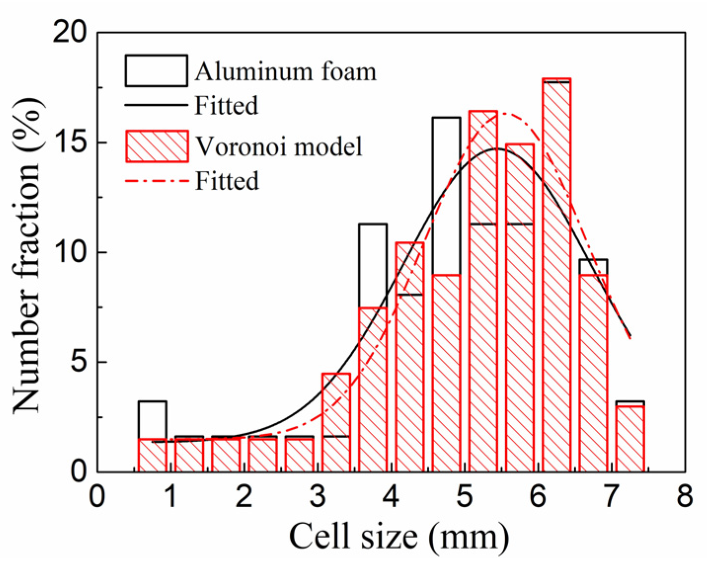
Three cross sections of 3D Voronoi foam model were extracted as shown in Figure 1c, similarly, three cross sections with the same size as the model section at different positions of the aluminum foam were cut by wire saw cutting, and the size and number of the cells in each section can be obtained based on the section images. The average cell size distributions for the different sections of the Voronoi foam model and the actual foam are presented in Figure 2. It can be found that the fitted curve of the cell size distribution for Voronoi foam model is similar to that for actual foam on the whole, and the ratios of the number of cells with a size of 4.5–6.5 mm to the total cell number are 58.2 and 56.5% respectively for the model and the foam, indicating that the Voronoi foam model is satisfactory with regard to the cell size distribution.
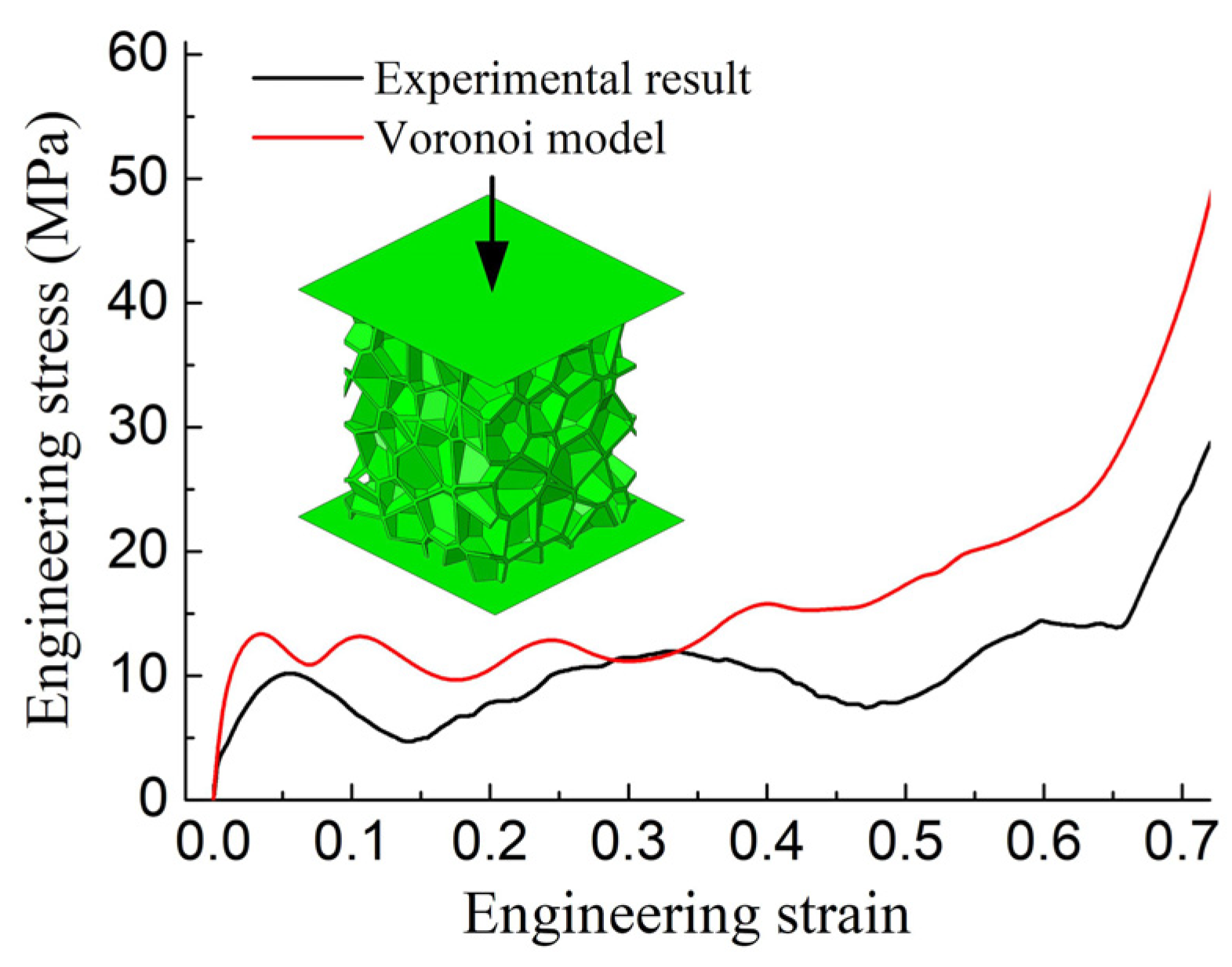
Additionally, the numerical uniaxial compression of 3D Voronoi foam was performed using Abaqus/standard. The Voronoi foam model with the dimension of 20 mm × 20 mm × 25 mm was set between two rigid plates, and the top rigid plate moved toward the bottom fixed rigid plate at a velocity of 1.5 mm/min. The cell wall material was described by an elastoplastic and isotropic constitutive behavior with isotropic hardening, and the relevant material constants were obtained from the study [28] and are listed in Table 1. The foam and rigid plates were modeled by C3D4 and R3D4 elements respectively. Figure 3 exhibits the compressive stress-strain curve of the foam model, and it can be seen that the difference between the simulated curve and experimental curve [8] is not significant; furthermore, a typical long plateau stage occurs on the curve, which agreed well with the actual closed-cell aluminum foam compression. Then, it is considered that the closed-cell aluminum foam can be effectively modeled by the constructed Voronoi foam model.

2.2. FE Model for the Numerical Simulation of MPF Process

The plastic forming of doubly curved AFSPs was numerically analyzed by Abaqus/explicit, and the sandwich geometric model with two 1-mm-thick face sheets and a 10-mm-thick Voronoi foam core was built without considering the adhesive layer, and a tie contact model was used to bond the face sheets with the foam core. To save the calculation time, only 1/4 AFSP model was applied in the simulation, and the length and width of the model are 200 and 150 mm. The 5052 aluminum alloy face sheet was characterized by an elastoplastic isotropic hardening behavior and the core cell wall material was defined the same as the foam in the numerical compression, and detailed material parameters of AFSP are provided in Table 1. C3D6 and C3D4 elements were chosen to mesh the face sheet and the core respectively, and the upper and lower multi-point dies composed of 21 × 16 rigid punches were modeled by R3D4 elements. Besides, 10-mm-thick elastic cushions meshed by C3D8R elements were placed between the multi-point die and the sandwich panel, and the friction coefficient between die and elastic cushion was set to be 0.2 and that between elastic cushion and sandwich panel was taken as 0.1 [29]. Mass scaling with a factor of 400 was applied to control the stable time increment and increase computational efficiency. The server CPU is E5-2620 V4 and the RAM is 32GB. The FE model for the MPF of a saddle-shaped AFSP is shown in Figure 4.

3. Numerical Results Analysis

3.1. Deformation Characteristics of Voronoi AFSP

To gain further insight into the plastic forming of spherical and saddle-shaped AFSPs, the deformation characteristics of AFSPs were analyzed in terms of the equivalent stress and strain distributed on the deformed sandwich panels.
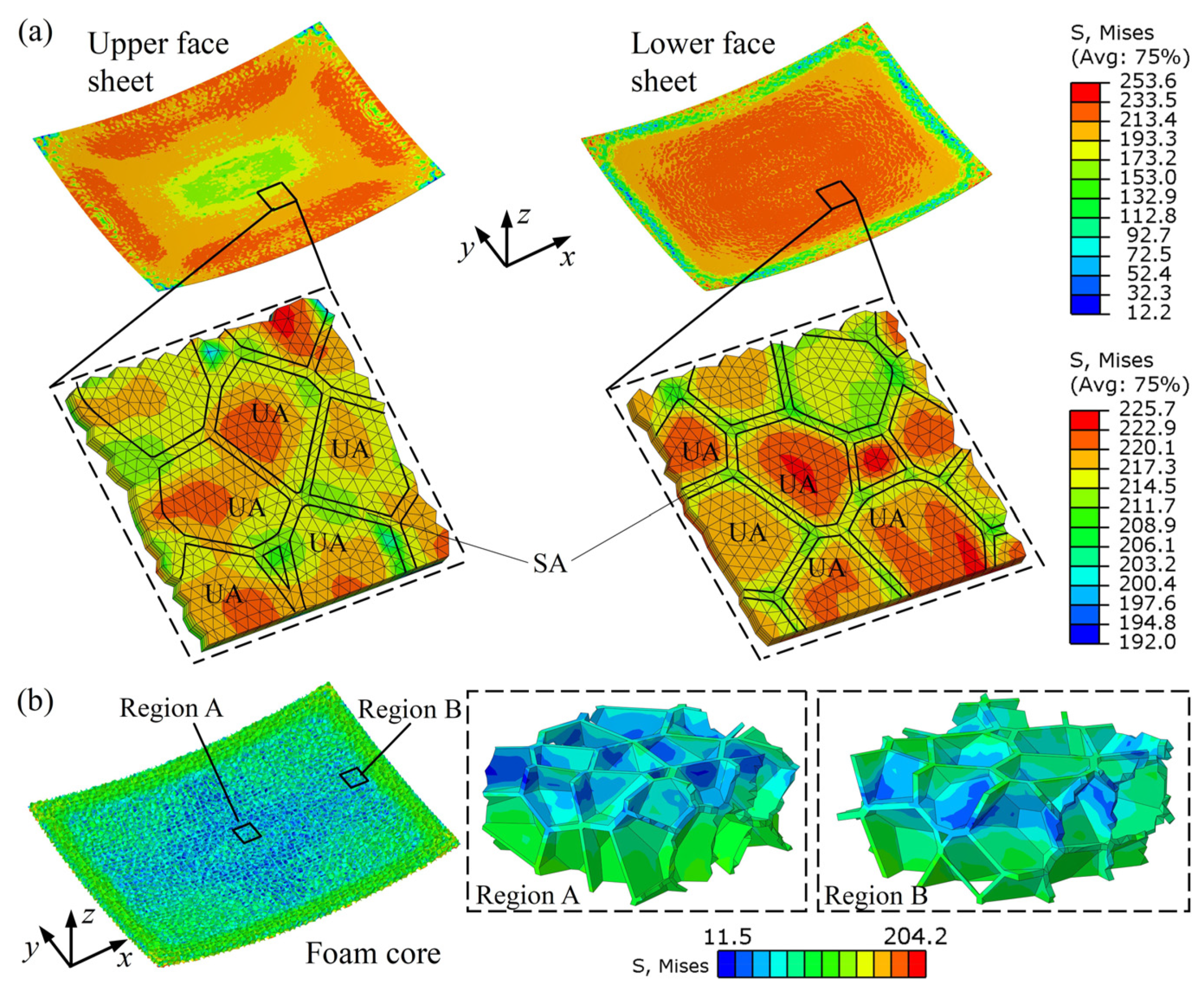
Figure 5a illustrates the equivalent stresses distributed on the face sheets of the spherical AFSP with the target radius of 800 mm. It can be seen that the stress is large in the region near the midpoints of edges of the upper face, while the large stress is mainly concentrated in the central region for the case of the lower face. Besides, there is a great difference between the stresses in the supported area (SA) of the face sheet and the unsupported area (UA) of the face sheet, and the stress in the SA where the face sheet is supported by the core cell walls is smaller than that in the UA where the face sheet lacks the support of the core cell walls. The equivalent stress distribution on the inner core of the spherical AFSP is displayed in Figure 5b, and the stress is small in the central region of the core and become large in the vicinity of the core edges. The similar distributed patterns of the stress on the cores in the regions A and B indicates that the stress distributed on the core cell walls near the upper face sheet is smaller in spherical sandwich panels forming.
As far as a saddle-shaped AFSP with the target radius of 800 mm is concerned, the equivalent stresses distributed on the face sheets are shown in Figure 6a. It can be found that the maximum equivalent stress on the saddle-shaped surface is approaching that on the spherical surface, and the stress in the SA is smaller than that in the UA. However, the distributed patterns of the stress on the face sheets with negative and positive Gaussian curvatures are slightly different. For the saddle-shaped panels forming, the stress is large near the midpoints of the shorter edges of the upper face and small in the region near the midpoints of the longer edges of the upper face, which is contrary to the case of the lower face. Figure 6b shows the stress distribution on the foam core of the AFSP. Large stress is concentrated in the region near midpoints of the edges of the core, and the maximum stress is smaller than that on the core of a spherical AFSP with the same radius. For the foam core in the region A near the midpoint of the longer edge, the stress on the cell walls which are near the upper face is smaller than that on the cell walls near the lower face, but for the core in the region B near the midpoint of the shorter edge, the stress is larger on the cell walls near the upper face.
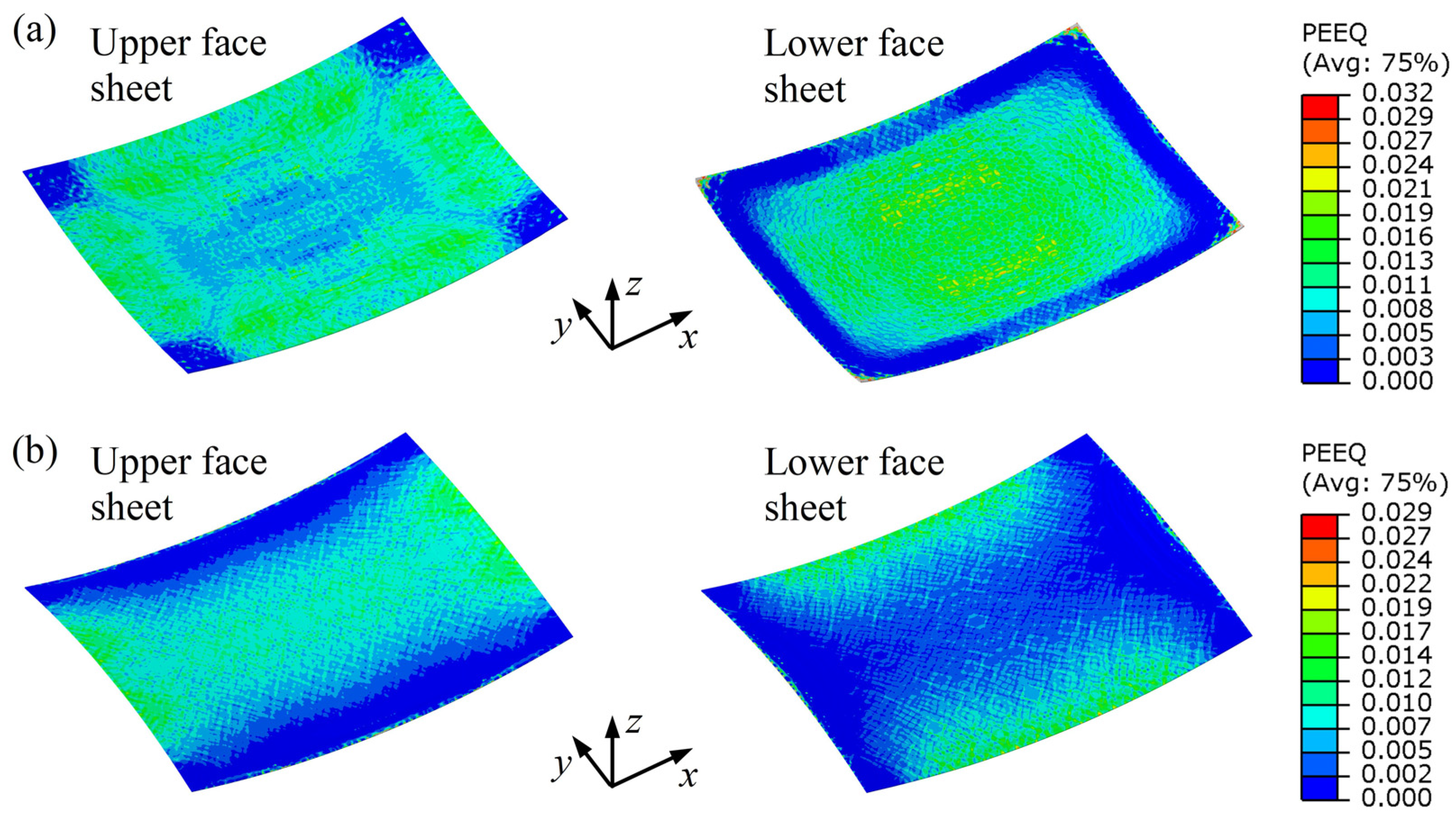
The corresponding equivalent strains distributed on the deformed sandwich panels were also analyzed. As shown in Figure 7a, the strain is large near the midpoints of four edges of the upper face and relatively small in the region near four corners and center of the upper face of the spherical sandwich AFSP, which is similar to the forming of spherical monolithic sheet; however, large deformations are concentrated in the central region of the lower face. For the saddle-shaped panel, it can be obtained from Figure 7b that the deformations on the upper face mainly occur in the region near the xz symmetrical plane of the panel, while the large deformations on the lower face are concentrated in the vicinity of the midpoints of the longer edges.
Equivalent strains distributed on the inner foam cores of the spherical and saddle-shaped AFSPs are displayed in Figure 8a and b respectively. It can be seen from Figure 8a that the large deformations appear in the region near four edges of the core and the strain is relatively small near the core center. Furthermore, the strain distributions on the cross sections OA and OB which are along the xz and yz symmetrical planes reveal that the large core deformations mainly occur on the cell walls near the lower face sheet during spherical panels forming.
As can be seen in Figure 8b, large deformations focus near the edges of the foam core, which is similar to the distributed pattern of the strain on the spherical core on the whole. Two cross sections were taken from the saddle-shaped core at the same positions as the sections of the spherical core, and it can be observed that the strain distributed on the section OA is larger near the upper face, which suggests that the large deformations of the inner core near the xz symmetrical plane mainly occur on the core cell walls near the upper face. The strain distribution on the section OB shows that the deformation of the cell walls near the upper face is greater for the central region of the core, while the cell walls close to the lower face were deformed more severely than those near the upper face for the region near the midpoint of the longer edge.

3.2. Forming Defects of Voronoi AFSP

Defects that affect the forming quality of the sandwich panel may occur after the large plastic deformation of AFSP, and the forming defects in spherical and saddle-shaped AFSPs forming are numerically investigated in this section. Figure 9 shows the numerical result of the spherical AFSP with a target radius of 400 mm, and the dimples can be observed in the region near the edges of the upper face. The reason for the appearance of the dimples is that the upper face sheet is subjected to the biaxial compressive stress during spherical panels forming, and the UA of the upper face sheet will buckle into the inner space of foam core cell.
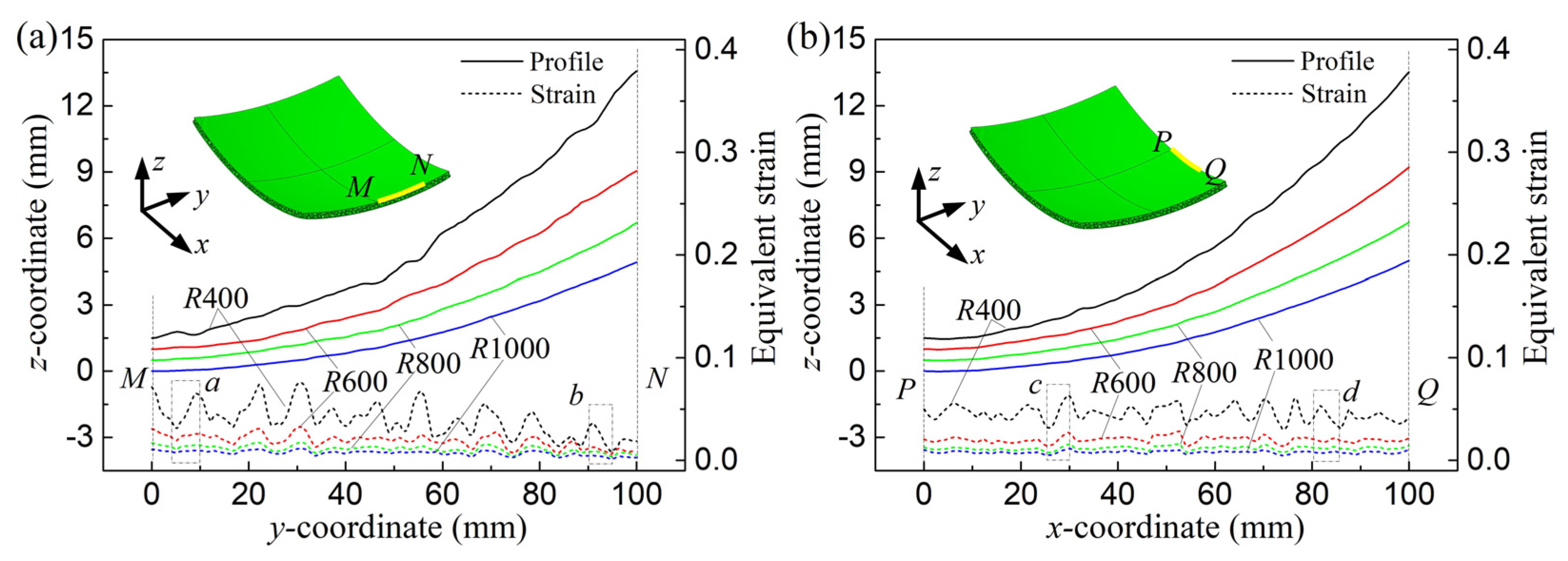
To characterize the dimples on the upper face specifically, the face sheet profiles along MN on the shorter edge and PQ on the longer edge when the spherical surfaces of AFSPs were shaped with different target radii are plotted in Figure 10a,b, and the equivalent strain distributions along MN and PQ are presented as well. When the radius is 400 mm, it can be observed that there are dimples on the profiles, and the strains distributed along the edges also fluctuate significantly. With a larger forming radius of 600 mm, dimples still occurred on the profiles but they are not as obvious as those occurred with the radius of 400 mm, and the fluctuation of the strain distribution on the face sheet is reduced. The smooth profiles and the strains evenly distributed on the upper face along MN and PQ means that face dimpling will not take place when the radius is greater than 600 mm.
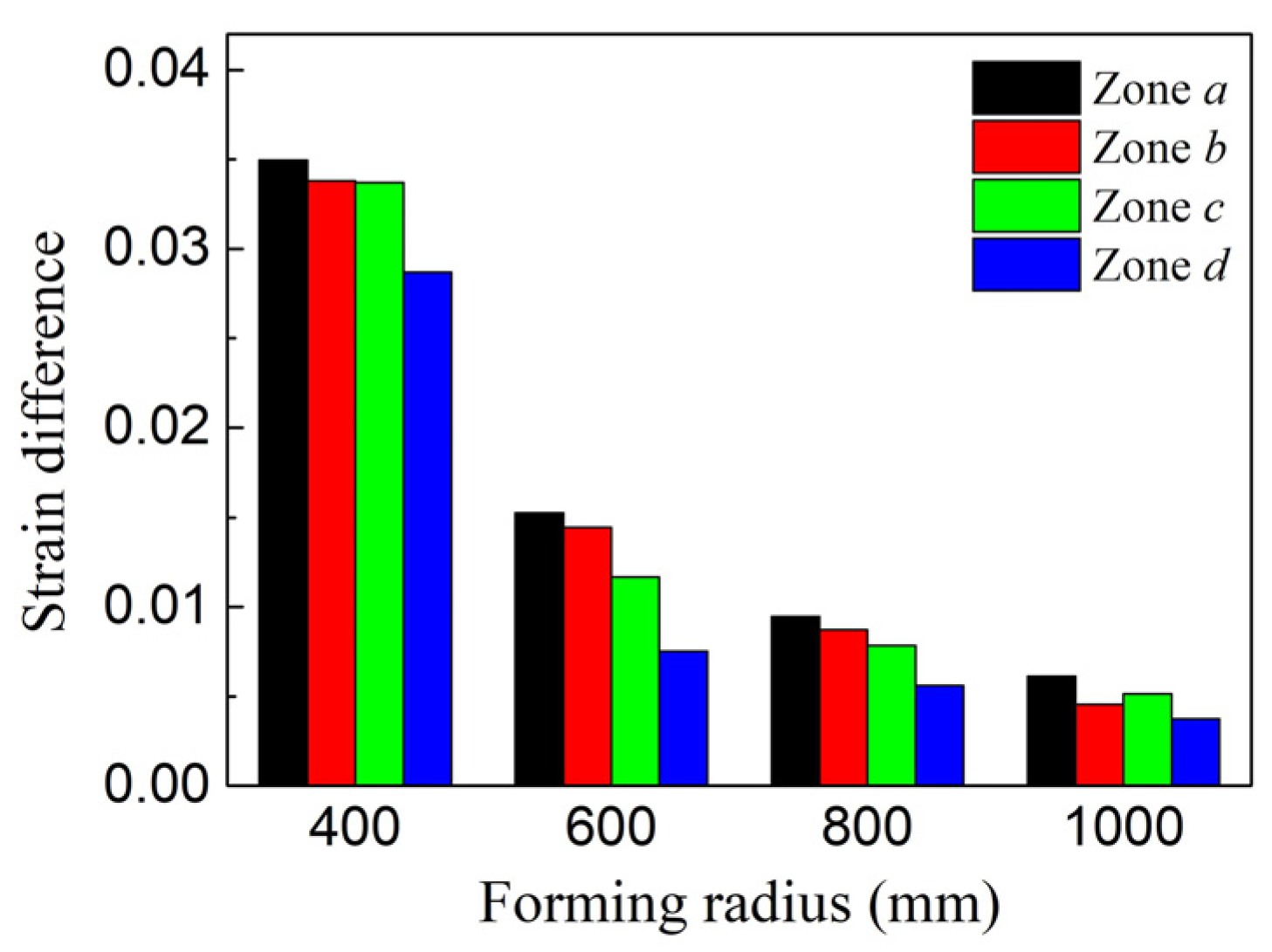
Zones a and b which are near and away from the midpoint of the shorter edge were selected as shown in Figure 10a, and zones c and d which are in the vicinity of and away from the midpoint of the longer edge were taken as shown in Figure 10b. The maximum strain difference for the upper face sheet in the selected zone can be calculated, and Figure 11 shows the maximum strain differences for the zones a, b, c, and d. It can be seen that the smaller the radius is, the larger the maximum strain difference is, and the differences for four zones reach the maximum with the values of 0.0350, 0.0338, 0.0337, and 0.0287 respectively when the forming radius is 400 mm. As the radius is larger than 600 mm, the maximum strain differences for the zones are not more than 0.01, indicating that face dimpling can be avoided effectively by increasing the forming radius. Besides, it can be found that the maximum strain difference for zone a is always greater than that for zone b in the case of different target radii, likewise, the strain difference for zone c is always larger than that for zone d, which suggests that the face dimpling is more obvious in the vicinity of the midpoint of the edge.
Figure 12 shows the illumination map of the lower face sheet of the spherical AFSP with the radius of 400 mm, and numerous bulges can be found on the lower face of the sandwich panel, which is caused by the compression of the foam core cell walls to the face sheet during the forming process, and the shape error in the normal direction on the lower face of the simulated spherical part reflects the face bulges more clearly.
The part surrounded by the red rectangle on the face sheet was selected as shown in Figure 12, and the equivalent strains distributed in the selected region of the lower face of the spherical AFSPs with different target radii are illustrated in Figure 13. It can be seen that there is a significant difference between the strains in the SA and the UA of the lower face sheet, and the smaller the target radius, the larger the strain difference is, and the more remarkable the bulge will be. The maximum strain difference reaches 0.016 when the target forming radius is 400 mm, and the strain difference is reduced with a larger radius of 600 mm and the maximum value is 0.013. As the forming radius increases to 800 mm and 1000 mm, the maximum strain differences are only 0.007 and 0.005 respectively.
As for the saddle-shaped AFSPs forming, Figure 14a shows that obvious dimples appeared on the lower face sheet of the sandwich panel with a target radius of 400 mm, and the lower face profiles and the strain distributions along UV are displayed in Figure 14b. It can be seen that there are dimples on the profiles and obvious fluctuations on the strain distribution curves for the case of the saddle-shaped panels with the target radii of 400 and 600 mm, and the lower face profiles become quite smooth and the strain distributions change little along UV when the radius increases to 800 and 1000 mm, implying that defects will not occur on the face when the radius exceeds 600 mm.
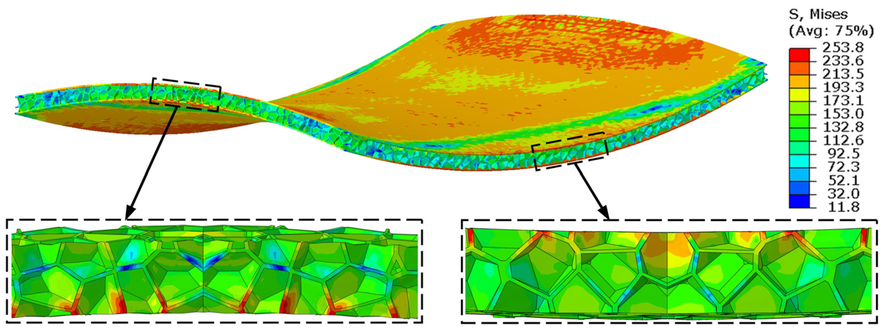
Except for the forming defects on the face sheet, core fracture defect is also considered. Based on the deformation characteristics of spherical and saddle-shaped AFSPs in Section 3.1, it can be found that large deformation mainly occurs near the midpoints of the edges of the sandwich panel, which suggests that core fracture may appear in the vicinity of the midpoints of the edges during doubly curved panels forming. A saddle-shaped AFSP was used as an example and Figure 15 shows the equivalent stress distributed on the deformed panel with a target radius of 600 mm. It can be seen that the stress distributed near the midpoints of the edges is higher for the core, and the foam core may crack at the corresponding positions after forming.

4. Experimental Validation

4.1. Multi-Point Forming Experiment

To verify the numerical analyses on the plastic forming of doubly curved AFSPs using 3D Voronoi AFSP model, spherical and saddle-shaped AFSPs with different target forming radii were formed by a series of MPF experiments. MPF is an advanced flexible technique for manufacturing 3D sheet metal parts. A pair of matrices of punch elements was applied in the procedure, and the required die surface can be obtained with a short time and a very low cost by changing the positions of the punch elements.
Figure 16 shows the MPF process of a saddle-shaped AFSP. The upper and lower multi-point dies were made up of 42 × 32 punch elements with the hemispheric tip whose radius is 10 mm, and the dimension in plan-view of the whole die is 420 mm × 320 mm. AFSPs used in the experiment were supplied by YuanTaida New Material Co., Ltd. (Sichuan, China). The material of face sheet is aluminum alloy 5052 and the closed-cell aluminum foam core with the density of 0.57g/cm3 was manufactured with pure aluminum by a melting foaming method and cut from the large foam block, and the sandwich panel was obtained through hot pressing adhesive bonding. The size of the rectangular AFSP is 400 mm × 300 mm × 12 mm, and the thicknesses of the face sheet and the foam core are 1 and 10 mm respectively. Moreover, two polyurethane cushions with the thickness of 10 mm were placed between the sandwich panel and the multi-point die.

4.2. Experimental Results and Analyses

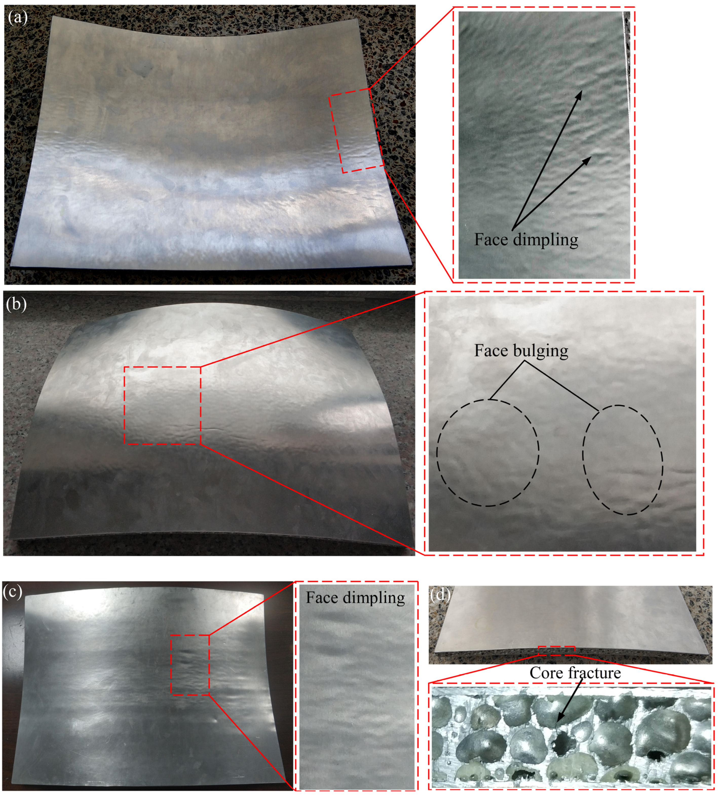
Figure 17a shows that there are numerous dimples in the regions near the midpoints of the edges of the upper face sheet of the spherical part with the target radius of 400 mm, which is close to the numerical result of the face dimpling defect in Figure 9; besides, a great number of bulges can be observed on the lower face sheet of the same shaped part as shown in Figure 17b, which is in good agreement with the illumination map of the lower surface in Figure 12. As for a saddle-shaped part with the target radius of 600 mm, it can be seen from Figure 17c that the dimples appeared near the center of the lower face sheet, which indicates the accuracy of the simulated results in Figure 14. The analyses on the deformation characteristics of a saddle-shaped core were verified by the crack occurred on the core cell wall near the midpoint of the shorter edge as shown in Figure 17d. Besides, no de-bonding defect was found in the practical products, and it is proved that the sandwich panel model without considering the adhesive layer is acceptable. Based on the above experimental results, it can be concluded that mesoscopic Voronoi AFSP model can reveal the forming defects occurred in doubly curved AFSPs forming accurately.
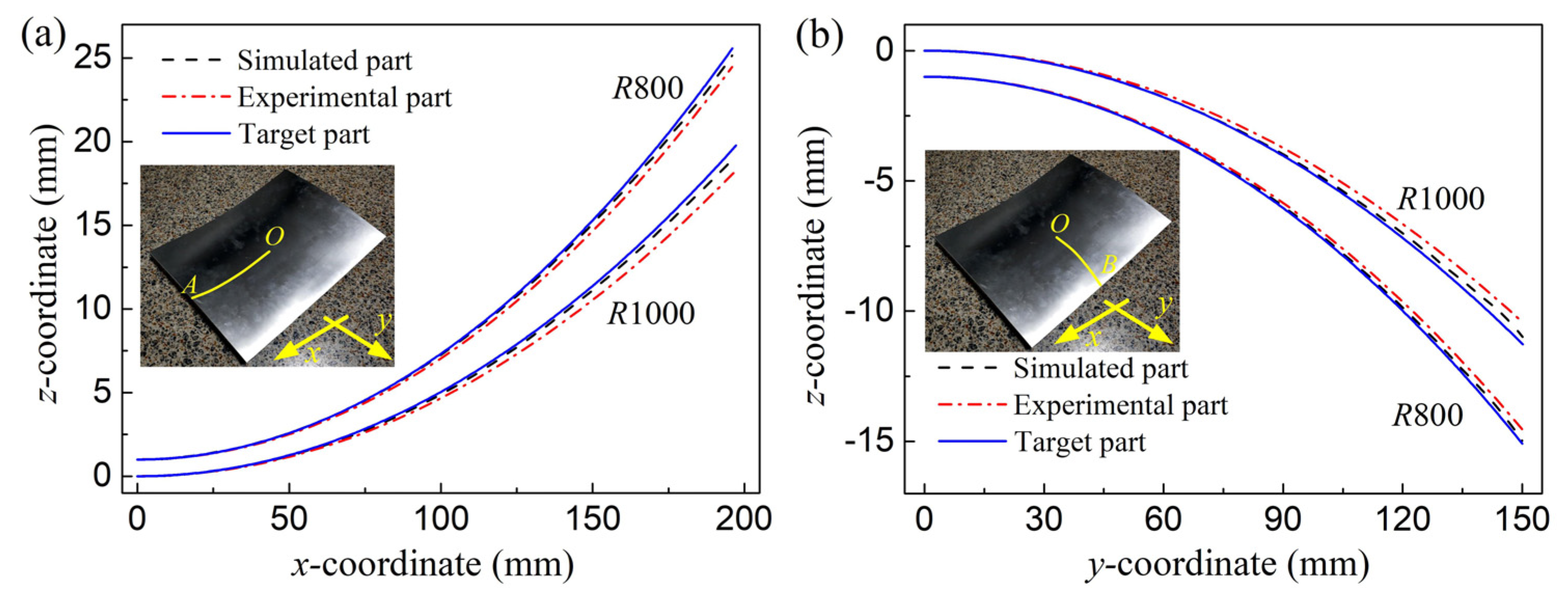
To further verify the simulated results obtained using Voronoi AFSP model, the experimental parts were scanned by the laser scanner, and the corresponding point-cloud data were imported into Geomagic Qualify and the shapes of the formed sandwich panels were rebuilt, and then, the surfaces of the simulated, experimental, and desired parts were compared using the best fit alignment. Figure 18a,b present the cross profiles of the upper face along the symmetrical planes OA and OB for the spherical parts without forming defects when the target radii are 800 and 1000 mm. It can be seen that for both simulated and practical parts, the closer to the edge of the face sheet, the larger the shape error between the shaped part and the desired part, and the shape of the simulated part is closer to that of the desired part. As for the saddle-shaped parts with different target radii of 800 and 1000 mm, the upper face profiles along the symmetrical planes OA and OB are plotted in Figure 19a,b. Similar to the spherical panels forming, the distance between the profile of the shaped part and that of the desired part reaches the maximum near the edges of the face sheet, and the shape error of the simulated part is smaller.
Average shape error is defined to quantitatively assess the forming accuracy of the simulated and practical parts:
e a v e = 1 N i = 1 N ( z i f - z i d ) 2
where N is the number of the measuring points, and zif and zid represent the z-coordinates of the ith measuring point on the formed and desired shapes respectively.
The average shape errors for the upper faces of doubly curved parts with the radii of 800 and 1000 mm are summarized in Table 2. It can be found that the error increases with the increase of the radius, and the errors of the experimental part are always larger than those of the simulated parts and the errors of the spherical parts are larger than those of the saddle-shaped parts in the case of the same radius. Besides, the average shape error of the upper face along OA is larger than that along OB for both spherical and saddle-shaped parts, which implies that the forming accuracy of the sandwich panel is higher along the shorter symmetrical axis.
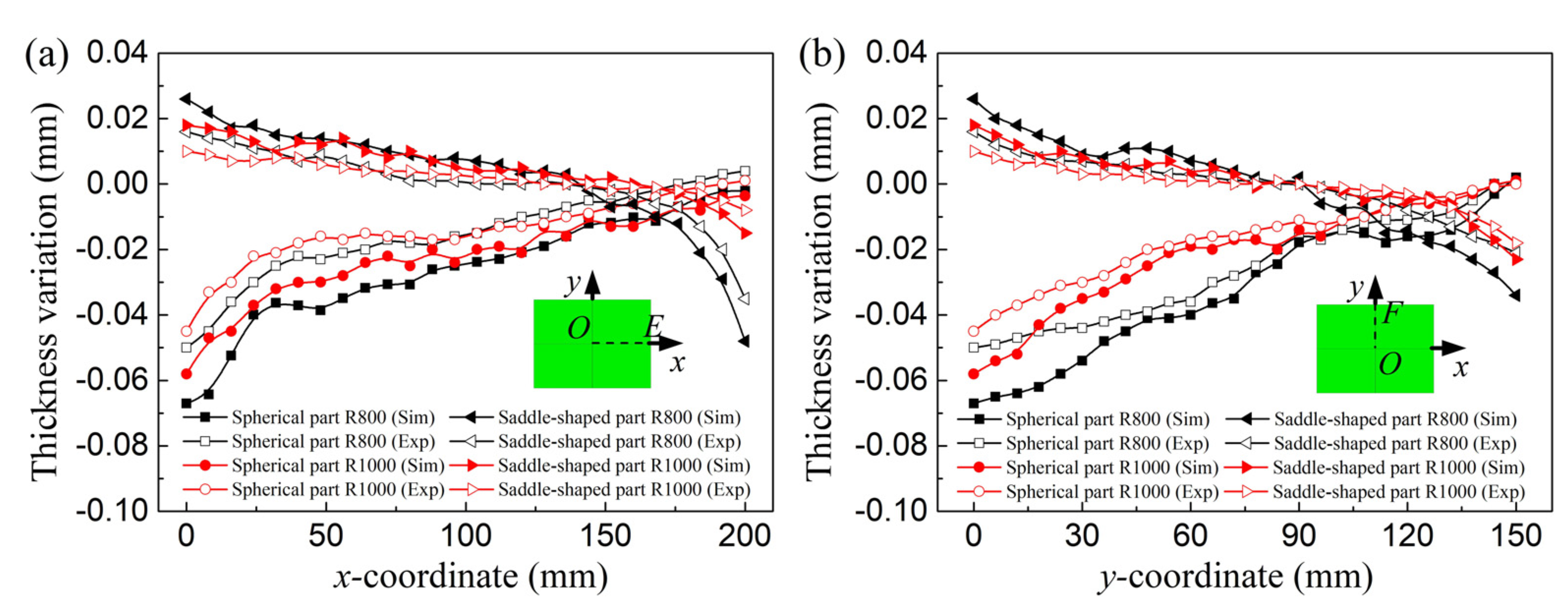
In addition to the shape error, the thickness variations of the shaped parts were also researched. The thicknesses of the simulated and experimental parts with the target radii of 800 and 1000 mm were measured at twenty-six measuring points which are uniformly distributed on the dash lines OE and OF which are along the x and y symmetrical axes, and the corresponding thickness variations of the parts can be obtained as plotted in Figure 20a,b. It can be found that the thickness variations of the spherical AFSPs along two symmetrical axes are similar, and the central regions of the spherical sandwich panel become thinner after forming, and the closer to the edge, the smaller the thickness variation of the panel is. Unlike a spherical AFSP, the thickness of the central region of a saddle-shaped panel increases after forming, and the closer to the edge, the thinner the panel is. Besides, Figure 20 shows that the thickness variation of the panel decreases with the increase of the target forming radius, and the thickness variation of the simulated part using Voronoi sandwich model is slightly larger than that of the experimental part.
Average thickness variation of the deformed sandwich panel can be obtained by calculating the average of the absolute value of the thickness change at different measuring points, and the average thickness variations of the simulated and practical parts in the doubly curved panels forming with different target radii are given in Table 3. It can be found that the panel thickness changes more greatly during the spherical panels forming and the average thickness variation of the simulated part is always slightly larger than that of the experimental part with the same target radius; moreover, the difference between the average thickness variation of the formed panels along OE and OF is small.

5. Conclusions

In this work, 3D mesoscopic Voronoi AFSP model was applied to research the plastic forming of spherical and saddle-shaped AFSPs numerically, and MPF experiments were carried out to shape the doubly curved surfaces of the sandwich panels with different target radii, and the following conclusions can be drawn:
1. Large deformations are mainly concentrated in the regions near the midpoints of the four edges of a spherical AFSP, and the deformations are larger near the midpoints of the shorter edge of the upper face and the longer edge of the lower face for the case of saddle-shaped panels forming. Besides, the stress of the face sheet in the UA is always larger than that in the SA for both spherical and saddle-shaped parts.
2. The numerical and experimental results illustrate that when the target radius does not exceed 600 mm, there were dimples in the vicinity of the midpoints of four edges of the upper face and bulges in the central region of the lower face during spherical AFSPs forming, and dimples also occurred near the center of the lower face of the saddle-shaped part. The large deformations on the cell walls near the midpoints of the edges of the panel suggest that the core may crack here.
3. The forming accuracy of the spherical panel is higher than that of the saddle-shaped panel with the identical target radius, and the formed surfaces are closer to the desired surface along the shorter symmetrical axis for both the parts. Besides, the thinning is severe in the center of the spherical AFSP after forming, and the panel thickness gradually increases from the center to the edge, which is opposite to the case of a saddle-shaped part.
4. For the plastic forming of doubly curved surfaces of AFSP, the larger the target radius, the smaller the average shape error and the average thickness variation of the sandwich panel are, and the shape error of the practical part is slightly larger than that of the simulated part and the thickness of actual panel changes less.

Author Contributions

Conceptualization, X.Z. and Z.C.; methodology, X.Z. and Z.C.; software, X.Z.; validation, X.Z., M.W., and Y.Z.; formal analysis, X.Z. and J.G.; investigation, X.Z.; resources, Q.C. and Z.C.; data curation, X.Z.; writing—original draft preparation, X.Z.; writing—review and editing, Q.C. and Z.C.; visualization, X.Z. and J.G.; supervision, Q.C. and Z.C.; project administration, Q.C. and Z.C.; funding acquisition, Z.C. All authors have read and agreed to the published version of the manuscript.

Funding

This research was funded by Natural Science Foundation of China (Grant No. 51975248) and Graduate Innovation Fund of Jilin University (Grant No. 101832020CX140).

Data Availability Statement

Not applicable.

Conflicts of Interest

The authors declare no conflict of interest.

References

  1. Banhart, J.; Seeliger, H.-W. Aluminium Foam Sandwich Panels: Manufacture, Metallurgy and Applications. Adv. Eng. Mater. 2008, 10, 793–802. [Google Scholar] [CrossRef]
  2. Crupi, V.; Epasto, G.; Guglielmino, E. Comparison of aluminium sandwiches for lightweight ship structures: Honeycomb vs. foam. Mar. Struct. 2013, 30, 74–96. [Google Scholar] [CrossRef]
  3. Schwingel, D.; Seeliger, HW.; Vecchionacci, C.; Alwes, D.; Dittrich, J. Aluminium foam sandwich structures for space applications. Acta Astronaut. 2007, 61, 326–330. [Google Scholar] [CrossRef]
  4. García-Moreno, F. Commercial Applications of Metal Foams: Their Properties and Production. Materials 2016, 9, 85. [Google Scholar] [CrossRef] [PubMed]
  5. Cai, Z.-Y.; Liang, X.-B.; Chen, Q.-M.; Zhang, X. Numerical and experimental investigations on the formability of three-dimensional aluminum alloy sandwich panels with egg-box-like cores. Int. J. Adv. Manuf. Technol. 2018, 99, 387–397. [Google Scholar] [CrossRef]
  6. Cai, Z.-Y.; Zhang, X.; Liang, X.-B. Multi-point forming of sandwich panels with egg-box-like cores and failure behaviors in forming process: Analytical models, numerical and experimental investigations. Mater. Des. 2018, 160, 1029–1041. [Google Scholar] [CrossRef]
  7. Liang, X.-B.; Cai, Z.-Y.; Zhang, X.; Gao, J.-X. Plastic forming of the doubly curved surfaces of sandwich plates with bi-directionally trapezoidal cores of different sizes. Thin-Walled Struct. 2020, 146, 106188. [Google Scholar] [CrossRef]
  8. Zhang, X.; Cai, Z.-Y.; Liang, X.-B.; Gao, J.-X. Numerical investigation on the plastic forming of aluminum foam sandwich panel based on three-dimensional mesoscopic and macroscopic models. Int. J. Adv. Manuf. Technol. 2020, 109, 1431–1445. [Google Scholar] [CrossRef]
  9. Kabir, K.; Vodenitcharova, T.; Hoffman, M. Response of aluminium foam-cored sandwich panels to bending load. Compos. Part B Eng. 2014, 64, 24–32. [Google Scholar] [CrossRef]
  10. Crupi, V.; Montanini, R. Aluminium foam sandwiches collapse modes under static and dynamic three-point bending. Int. J. Impact Eng. 2007, 34, 509–521. [Google Scholar] [CrossRef]
  11. Hanssen, A.; Girard, Y.; Olovsson, L.; Berstad, T.; Langseth, M. A numerical model for bird strike of aluminium foam-based sandwich panels. Int. J. Impact Eng. 2006, 32, 1127–1144. [Google Scholar] [CrossRef]
  12. Zhao, Y.; Yang, Z.H.; Yu, T.L.; Xin, D.B. Mechanical properties and energy absorption capabilities of aluminum foam sandwich structure subjected to low-velocity impact. Constr. Build. Mater. 2021, 273, 121996. [Google Scholar] [CrossRef]
  13. Jing, L.; Liu, K.; Su, X.; Guo, X. Experimental and numerical study of square sandwich panels with layered-gradient foam cores to air-blast loading. Thin-Walled Struct. 2021, 161, 107445. [Google Scholar] [CrossRef]
  14. Hou, W.; Zhu, F.; Lu, G.; Fang, D.-N. Ballistic impact experiments of metallic sandwich panels with aluminium foam core. Int. J. Impact Eng. 2010, 37, 1045–1055. [Google Scholar] [CrossRef]
  15. Jackson, K.; Allwood, J.; Landert, M. Incremental forming of sandwich panels. J. Mater. Process. Technol. 2008, 204, 290–303. [Google Scholar] [CrossRef]
  16. Seong, D.; Jung, C.; Yang, D.; Kim, J.; Chung, W.; Lee, M. Bendable metallic sandwich plates with a sheared dimple core. Scr. Mater. 2010, 63, 81–84. [Google Scholar] [CrossRef]
  17. Weiss, M.; Abeyrathna, B.; Pereira, M. Roll formability of aluminium foam sandwich panels. Int. J. Adv. Manuf. Technol. 2018, 97, 953–965. [Google Scholar] [CrossRef]
  18. Nayyeri, M.J.; Mirbagheri, S.M.H.; Fatmehsari, D.H. Numerical evaluation of the stacking effect of spheres on the mechanics of tailor-made aluminum foams. Compos. Struct. 2017, 159, 316–326. [Google Scholar] [CrossRef]
  19. Nammi, S.; Myler, P.; Edwards, G. Finite element analysis of closed-cell aluminium foam under quasi-static loading. Mater. Des. 2010, 31, 712–722. [Google Scholar] [CrossRef]
  20. Dou, R.; Qiu, S.; Ju, Y.; Hu, Y. Simulation of compression behavior and strain-rate effect for aluminum foam sandwich panels. Comput. Mater. Sci. 2016, 112, 205–209. [Google Scholar] [CrossRef]
  21. Vengatachalam, B.; Poh, L.H.; Liu, Z.S.; Qin, Q.H.; Swaddiwudhipong, S. Three dimensional modelling of closed-cell aluminium foams with predictive macroscopic behaviour. Mech. Mater. 2019, 136, 103067. [Google Scholar] [CrossRef]
  22. Contorno, D.; Filice, L.; Fratini, L.; Micari, F. Forming of aluminum foam sandwich panels: Numerical simulations and experimental tests. J. Mater. Process. Technol. 2006, 177, 364–367. [Google Scholar] [CrossRef]
  23. Nassar, H.; Albakri, M.; Pan, H.; Khraisheh, M. On the gas pressure forming of aluminium foam sandwich panels: Experiments and numerical simulations. CIRP Ann. 2012, 61, 243–246. [Google Scholar] [CrossRef]
  24. Bucher, T.; Cardenas, S.; Verma, R.; Li, W.; Yao, Y.L. Laser Forming of Sandwich Panels With Metal Foam Cores. J. Manuf. Sci. Eng. 2018, 140, 111015. [Google Scholar] [CrossRef] [Green Version]
  25. Li, M.; Cai, Z.; Sui, Z.; Yan, Q. Multi-point forming technology for sheet metal. J. Mater. Process. Technol. 2002, 129, 333–338. [Google Scholar] [CrossRef]
  26. Cai, Z.-Y.; Wang, S.-H.; Xu, X.-D.; Li, M.-Z. Numerical simulation for the multi-point stretch forming process of sheet metal. J. Mater. Process. Technol. 2009, 209, 396–407. [Google Scholar] [CrossRef]
  27. Gan, Y.; Chen, C.; Shen, Y. Three-dimensional modeling of the mechanical property of linearly elastic open cell foams. Int. J. Solids Struct. 2005, 42, 6628–6642. [Google Scholar] [CrossRef] [Green Version]
  28. Sun, G.; Wang, E.; Zhao, T.; Zheng, G.; Li, Q. Inverse identification of cell-wall material properties of closed-cell aluminum foams based upon Vickers nano-indentation tests. Int. J. Mech. Sci. 2020, 176, 105524. [Google Scholar] [CrossRef]
  29. Zhang, Q.; Dean, T.; Wang, Z. Numerical simulation of deformation in multi-point sandwich forming. Int. J. Mach. Tools Manuf. 2006, 46, 699–707. [Google Scholar] [CrossRef]
Figure 1. (a) closed-cell aluminum foam; (b) 3D Voronoi foam model; (c) cross sections of the Voronoi foam model.
Metals 11 00675 g001
Figure 2. Distribution of foam cell sizes.
Metals 11 00675 g002
Figure 3. Compressive stress–strain curves.
Metals 11 00675 g003
Figure 4. FE model for the numerical simulation on the MPF of saddle-shaped AFSP.
Metals 11 00675 g004
Figure 5. Equivalent stresses distributed on the spherical AFSP with a target radius of 800 mm. (a) Face sheet; (b) foam core.
Metals 11 00675 g005
Figure 6. Equivalent stresses distributed on the saddle-shaped AFSP with a target radius of 800 mm. (a) Face sheet; (b) foam core.
Metals 11 00675 g006
Figure 7. Equivalent strains distributed on the face sheets. (a) Spherical AFSP; (b) saddle-shaped AFSP.
Metals 11 00675 g007
Figure 8. Equivalent strains distributed on the foam cores and cross sections. (a) Spherical AFSP; (b) saddle-shaped AFSP.
Metals 11 00675 g008
Figure 9. Dimples on the upper face sheet of the spherical AFSP.
Metals 11 00675 g009
Figure 10. Upper face sheet profiles and equivalent strain distributions. (a) Along MN; (b) along PQ.
Metals 11 00675 g010
Figure 11. Maximum strain differences for the selected zones on the upper face sheet of the spherical AFSP with different target forming radii.
Metals 11 00675 g011
Figure 12. Bulges on the lower face sheet of the spherical AFSP.
Metals 11 00675 g012
Figure 13. Equivalent distributions in the selected region of the lower face sheets of the spherical AFSPs with different target radii.
Metals 11 00675 g013
Figure 14. (a) Dimples on the lower face sheet of the saddle-shaped AFSP; (b) lower face sheet profiles and equivalent strain distributions along UV.
Metals 11 00675 g014
Figure 15. Equivalent stress distributed on the saddle-shaped AFSP with a target radius of 600 mm.
Metals 11 00675 g015
Figure 16. Multi-point forming of AFSP.
Metals 11 00675 g016
Figure 17. MPF experimental AFSPs. (a) Dimples on the upper face sheet of the spherical panel; (b) bulges on the lower face sheet of the spherical panel; (c) dimples on the lower face sheet of the saddle-shaped panel; (d) crack on the core cell wall of the saddle-shaped panel.
Metals 11 00675 g017
Figure 18. Cross profiles of the upper face sheets of the spherical AFSPs with different target radii. (a) Along OA; (b) along OB.
Metals 11 00675 g018
Figure 19. Cross profiles of the upper face sheets of the saddle-shaped AFSPs with different target radii. (a) Along OA; (b) along OB.
Metals 11 00675 g019
Figure 20. Thickness variations of the spherical and saddle-shaped AFSPs with different target radii. (a) Along OE; (b) along OF.
Metals 11 00675 g020
Table 1. Material constants of sandwich panels.
Density (g/cm3)Young’s Modulus (MPa)Yield Stress (MPa)Poisson’s Ratio
Face sheet2.7170,3001930.33
Core cell wall2.763,000630.33
Table 2. Average shape errors of the upper face sheets of the doubly curved AFSPs (mm).
Radius (mm)Along OAAlong OB
SimExpSimExp
Spherical part8000.0230.2090.0170.081
10000.0430.3390.0320.124
Saddle-shaped part8000.0330.2400.0280.087
10000.0500.4400.0400.162
Table 3. Average thickness variations of the doubly curved AFSPs (mm).
Radius (mm)Along OEAlong OF
SimExpSimExp
Spherical part8000.0260.0160.0330.026
10000.0220.0150.0220.017
Saddle-shaped part8000.0130.0070.0130.007
10000.0080.0040.0070.004
Publisher’s Note: MDPI stays neutral with regard to jurisdictional claims in published maps and institutional affiliations.