Article

Human-Centered Robotic Development in the Steel Shop: Improving Health, Safety and Digital Skills at the Workplace

by
Valentina Colla
1,*,
Ruben Matino
1,
Antonius Johannes Schröder
2,
Mauro Schivalocchi
3 and
Lea Romaniello
4
1
Scuola Superiore Sant’Anna, TeCIP Institute, I-56124 Pisa, Tuscany, Italy
2
Sozialforschungsstelle, Technische Universität Dortmund, D-44339 Dortmund, Germany
3
Polytec, BM Group, I-38083 Borgo Chiese, Trentino, Italy
4
ArcelorMittal Italia, I-74123 Taranto, Taranto, Italy
*
Author to whom correspondence should be addressed.
Metals 2021, 11(4), 647; https://doi.org/10.3390/met11040647
Submission received: 13 March 2021 / Revised: 11 April 2021 / Accepted: 14 April 2021 / Published: 15 April 2021

Abstract

:
Within the implementation of the Industry 4.0 paradigm in the steel sector, robots can play a relevant role in improving health and safety conditions at the workplace, by overtaking cumbersome, repetitive and risky operations. However, the implementation of robotics solutions in this particular sector is hampered by harsh operating conditions and by particular features of many procedures, which require a combination of force and sensitivity. Human–robot cooperation is a viable solution to overcome existing barriers, by synergistically combining human and robot abilities in the sense of a human-centered Industry 5.0. In this sense, robotics solution should be designed in a way to integrate and meet the end-users’ demands in a common development process for successfully implementation and widely acceptance. The paper presents the outcomes of the field evaluation of a robotic workstation, which was designed for a complex maintenance operation that is daily performed in the steel shop. The system derives from a co-creation process, where workers were involved since the beginning in the design process, according to the paradigm of social innovation combining technological and social development. Therefore, the evaluation aimed at assessing both system reliability and end-users’ satisfaction. The results show that the human-centered robotic workstations are successful in reducing cumbersome operations and improving workers’ health and safety conditions, and that this fact is clearly perceived by system users and developers.

1. Introduction

The steel sector is undergoing a paramount transformation due to the progress of digitalization in all production stages. New tools and technologies are progressively spreading in all the areas of the steelworks, providing considerable advantages in terms of process efficiency and reliability, product quality and socio-economic and environmental sustainability [1,2]. However, such trend also poses some relevant challenges in terms of impact on workers and skill demand [3], which need to be addressed by the sector in order to fully exploit the potential of new tools and technologies [4].
Within the process of modernization and digitalization of the steelworks, furnaces monitoring, control and maintenance is one of the fields where advanced analyses as well as digital tools and techniques can provide the most relevant advantages in terms of improved product quality, process reliability and health and safety conditions for workers. Relevant examples in this sense are provided in [5], where components of furnace conveyors are considered; in [6], where a smart control for a steel slab reheating furnace is proposed; in [7], where an artificial intelligence-based bath temperature prediction model is presented; and in [8], where a model predictive control approach is applied to temperature control in an austenitization furnace.
In such modernization streamline, robotics is considered among the technologies which can play a not negligible role, especially in improving health and safety conditions of workplaces. In effects, robots could overtake the most cumbersome, repetitive and potentially harmful operations, by improving workplace as well as processes repeatability and reliability.
Indeed, in the steel sector the wide diffusion of robots is hampered and slowed down by the harsh environmental conditions, which are commonly found in most areas of the steelworks, such as high temperatures, presence of dusts, steam, off-gases and aggressive agents. Moreover, most applications of robotic systems in the steel field require the development of operations with high payload robots, which show many challenges beside the opportunities for improving workers’ health and safety, such as exemplarily discussed in [9]. However, an increasing interest is observed and some exemplary applications can be found in literature. A comprehensive analysis is developed in [10] concerning human interventions in the casting floor, which can be replaced by a robotic system, such as ladle oxygen opening (“lancing”), shroud manipulation and powder feeding. A more recent application of a robot for the same purpose as well as for inspection operations is discussed in [11]. An interesting review of the evolution of robotic applications in a continuous casting area is provided in [12]. In [13] a robotic system for the steel-strapping process of coils in the metals industry is described, where two six degrees of freedom (DOF) robotic arms cooperate in performing three different types of strapping modes. A comprehensive overview of the application of standard six axes industrial robots in different areas of the steel shop is given in [14]. The application of a robot for sublance handling in the Linz-Donawtz converter area is presented in [15]. Two applications of robots for liquid steel sampling operations are described in [16] and [17], while in [18] a robotic system for a tap hole opening in an electric arc furnace is presented, which lead to considerable benefits for both process reliability and workers’ safety. A further interesting robotic application for automated deburring of steel bars exploiting 3D stereo vision and machine learning techniques is proposed in [19]. On the other hand, robots are intensively applied in the sectors using the products of the steelworks, such as the automotive or aerospace industries. Exemplar applications can be found in literature concerning steel hot stamping [20], welding [21] and assembly [22], by also combing high payload and good precision for operations in large workspaces [23].
A major showstopper for the extensive application of robots in steelworks is represented by the fact that many operations require the combination of force and precision and, as a consequence, safety regulations impose supervision, monitoring and acknowledgment of the technical personnel. In all these cases, fully automated solutions do not represent a trustable and viable approach, while other paradigms, such as the implementation of an interactive human–robot cooperation, show higher chances of success. Recent studies also show that these approaches indicate the highest degree of social acceptance in the implementation of the Industry 4.0 paradigm [24].
In human–robot collaborative environments, the strengths and capabilities of both operators and robots are jointly exploited while respective limitations are overcome. Robots are robust and can easily sustain cumbersome and risky operations, while humans are fast and proficient in self-adapt their behavior to unforeseen situations and highly unstructured environments. In this context, the challenging tasks requiring sensitivity, advanced sensing and reasoning capabilities are left to the operators, while robots fully exploit their capability e.g., to handle high loads with high precision without depletion or to face harsher and potentially harmful tasks. The collaborative approach usually also reduces the need to invest in expensive equipment and sophisticated control strategies, but it still relieves workers from stressing, strenuous and repetitive tasks, which can expose them to potential risks for their health and safety [25]. On the other hand, the design of collaborative robotic workstation needs to carefully consider all the ergonomic aspects which ensure a safe, smooth and easy interaction between humans and robots [26].
Not only new technological possibilities to design the human–machine interface and interaction between robot and operator, but also a paradigm change to a human-centered innovation approach as outlined in the EU Policy Paper on Industry 5.0 [27], is improving the acceptance, implementation and evolvement of innovations at the workplace. This has to be done in a social innovation process combining technological development with social impact and support right from the beginning of the innovation process, including all the relevant stakeholders [28,29]. In this case, it means to start with a human-centered perspective on an effective human–robot task division within a social innovation process ensuring the integration of the operator experience and knowledge at the workplace. Safeguarding a mutual innovation and learning process will guarantee to unfold the full potential of the new robotic solution, while simultaneously increasing the qualification level of the related operators by adopting digital skills already during the development process.
Human–robot cooperation shows a relevant industrial importance for inspection and maintenance exploration in harsh conditions, for instance in hazardous or underwater environments [30]. It is already implemented in some standard production chains of manufacturing industry, for instance in the automotive industry [31,32]. In such context, for instance, an interesting study investigated a particular formulation of the flow shop scheduling problem, which is observed in a work cell, where one robot cooperates with one worker [33].
On the other hand, human–robot cooperation has been very rarely applied in the steel industry so far. An application of a semi-automated robotic system is proposed in [34] for the construction of the refractory wear of the steel converter, which jointly exploits a human–robot cooperative technology and a direct teaching method. A further example of human–robot interaction is presented in [35], which consists in an automated cartridge changer installed in an electric steelwork.
This paper presents the final outcomes of a project, which aimed at designing and developing a robotic workstation, applied to a complex maintenance operation in the steel shop. Such operation, which is currently manually performed in most steelworks, implies inspection, cleaning with oxygen lance and replacement of quite heavy refractory components of the so-called “sliding gate” of the ladle, after the completion of the steelmaking operations (i.e., when the ladle is still quite hot). In performing such maintenance operations, the workers are exposed to high temperatures as well as to risks for their health and safety. In particular, short term risks, concern hands and feet injuries, while long term risks refer to problems related to stress and back injuries due to repetitive strain. The robotic cell was finally installed and tested in a big Italian integrated steel company. The main features of this robotic workstation, which represents one of the first attempts to establish a human–robot cooperative environment in the harsh context of the steel shop, were already presented in the past in [36,37], but at that stage only preliminary although very encouraging test results were available. Here we present the results of the extensive field tests in the steelworks, where the whole maintenance operation was innovated with the support of a selected skilled team of technical operators.
Moreover, in the present investigation, a particular emphasis is provided to the assessment of the social innovation process, which was put in place in the design of the robotic workstation [38], combining the robot development with the knowledge, experience and suggestions of the workplace operators (and other company stakeholders) right from the beginning and during the whole innovation process. In effects since the very beginning a co-creation process was put in place for the system design, where the end-users were involved in the thorough analysis and elaboration of the functional requirements and specifications of the system as well as in the design of human–robot interaction and human–machine interface (HMI). Finally, the technical personnel were also deeply involved in the test stage, but this was only the last although fundamental stage of their involvement, which provided the opportunity for final adjustments and tuning of some features and tools of the robotic cell. As a consequence, the purpose of the present investigation is not only to verify the proper achievement of the technical targets of the system, through a validation of its functionalities, but also the assessment of the performed social innovation process among the involved actors, mainly developers and operators, and the perception of the system. In rough words, the target question here is not only if the system properly works, but also if the way it was designed involved the relevant people effectively and paves the way to its full exploitation in the real industrial context.
The paper is organized as follows: Section 2 provides a description of the concerned maintenance operation, of the main components of the robotic workstation as well as of the methodology followed for assessing the functionality and the impact on the workers. Section 3 presents the assessment results, while Section 4 discusses the obtained outcomes of the final system evaluation. Finally, Section 5 provides some concluding remarks and hints for future work.

2. Materials and Methods

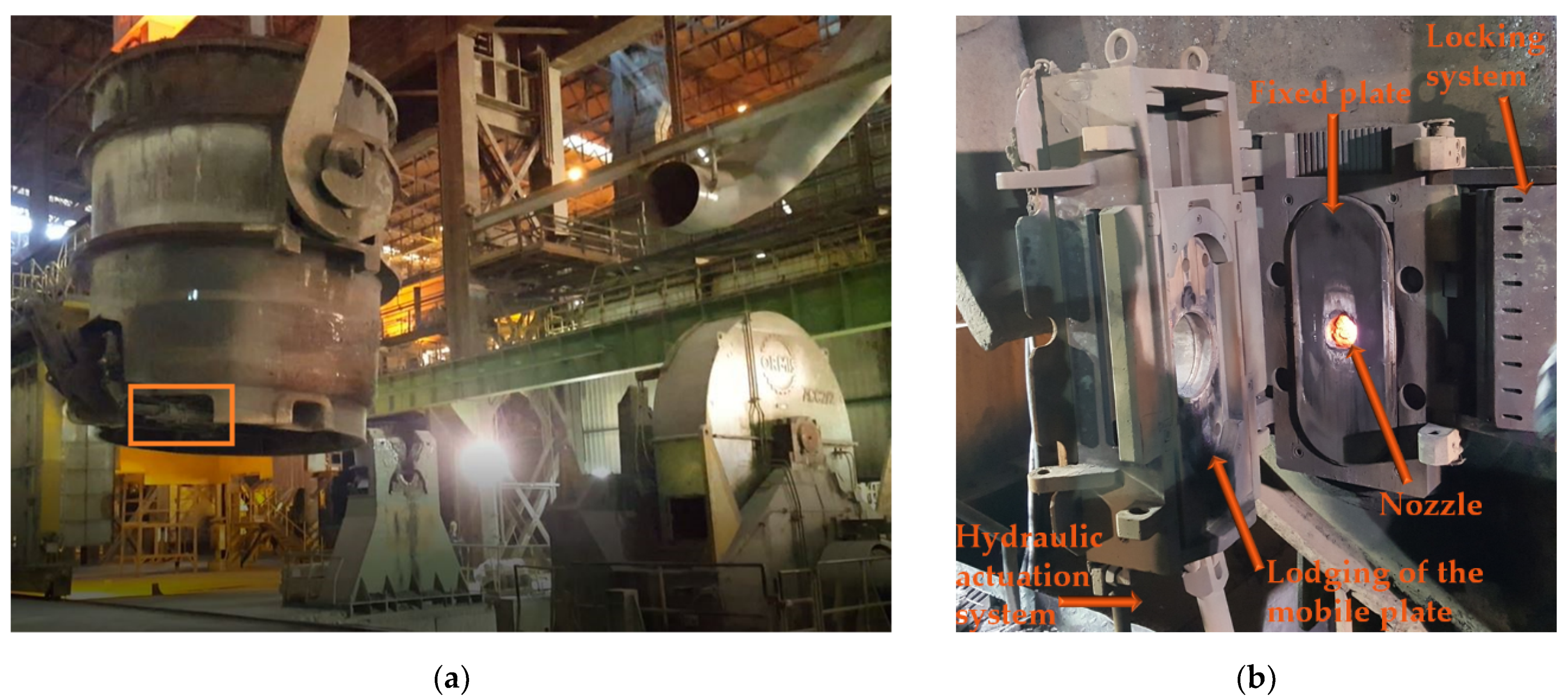
2.1. The Maintenance of the Ladle Sliding Gate

In the steel production cycle, the ladle is a container in which the decarburization of the pig iron and the steel chemistry refinement take place. Afterwards, through the ladle, the molten steel is transferred to the continuous casting station, where it is casted and solidified into semi-finished products (e.g., billets, blooms or slabs). The sliding gate is a device located at the bottom of the ladle (identified by an orange rectangle in Figure 1a) hosting the tap hole, through which the liquid steel flows toward the tundish of the caster. The sliding gate regulates the flow of the liquid steel through its mobile component, which is actuated by means of a hydraulic cylinder, and is subjected to wear and deposition of residues of solidified steel. Therefore, at the end of each tapping phase, the ladle is carried to an ad-hoc equipped maintenance area (shown in Figure 1a as well) within the steel shop, where it is flipped and rotated of about 90°, in order to allow maintaining the sliding gate. Such operation, which is usually manually performed by skilled operators, consists of cleaning or replacing all the refractory components of the sliding gate and developing other necessary monitoring and cleaning operations.
In the ladle maintenance area, a platform allows the access to the bottom of the ladle by the technical personnel (usually two persons), who open the sliding gate through a leverage mechanism, clean the tap hole through an oxygen lance, inspect and eventually replace the different refractory components, if they are worn, by exploiting a series of tools to facilitate the operation and reducing the efforts. The duration of the operation generally lies between 25 and 30 min, and the workers are exposed to quite relevant temperatures, as the temperature of the ladle bottom is around 70 °C.
The particular sliding gate, which was considered in the described application, is depicted in Figure 1b. The main refractory components are two plates (one mounted on the external mobile part of the sliding gate, usually named mobile plate, and the so-called fixed plate, which is closer to the ladle bottom) and a discharger, which is inserted in the internal channel, through which the liquid steel flows. Some components are replaced after each cast, while other ones are replaced after a limited number of subsequent casts (generally 5 or 6), also depending on the wear status. The perfect adherence of the refractory component to the sliding gate is ensured by a layer of adhesive mortar. Each component needs to be precisely placed in its lodging, as an even minimal misalignment can imply a very dangerous leak of liquid steel during operations, and the required placement accuracy is in the order of magnitude of the millimeter.
To sum up, the maintenance of the ladle sling gate is a very complex operation, which requires both force (as the weight of the refractory components is considerable, for one of the pieces it lies around 20 Kg) and precision, and heavily depends on the wear conditions that are found after each cast. This is the reason why such operation is still manual in most steelworks, and it is difficult to make it fully automatic. The total duration of the operation is variable and depends on the need to replace some refractory components, but generally lies between 20 and 30 min.
In order to design the robotic workstation, the maintenance procedure was subdivided into a series of elementary operations with associated used tools, concerned components of the sliding gate to remove or place, and eventual associated risks for the workers. Such list is shown in the second column of Table 1.
Moreover, as an important part of combining technological possibilities with human requirements, the choice was made to focus the human intervention on the operations which are associated to the higher risks. Therefore, a human–robot cooperative environment was selected, in which the robot develops the most cumbersome tasks, such as raising of heavy weights and handling the oxygen lance, by reducing the time of exposure to heat, dust and sparks (although, in any case, all the operators always wear safety equipment). On the other hand, the human intervention remains necessary on those operations, which require complex automation design, but are clearly affordable for the operators, such the connection/disconnection of the hydraulic hoses used to manipulate the sliding gate for final verification of its functionality, and the application of a uniform layer of mortar on the refractory components.

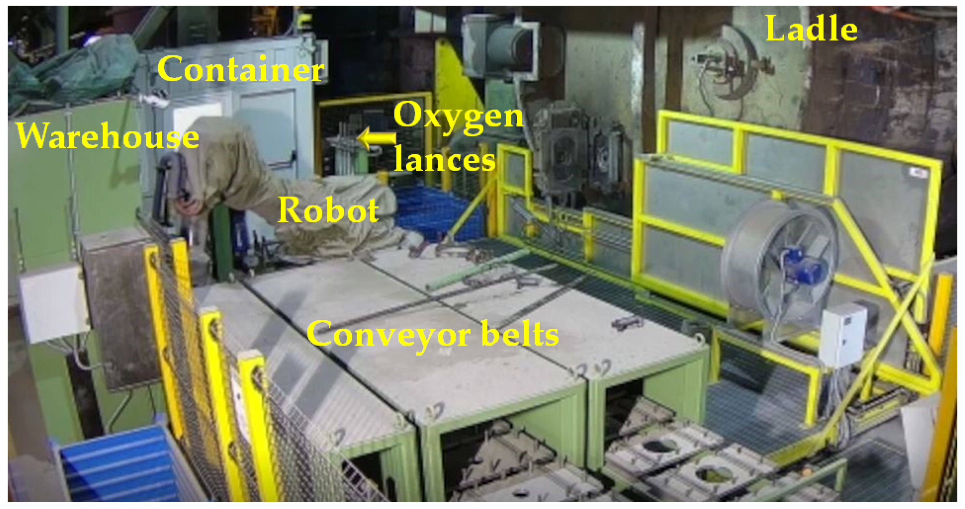
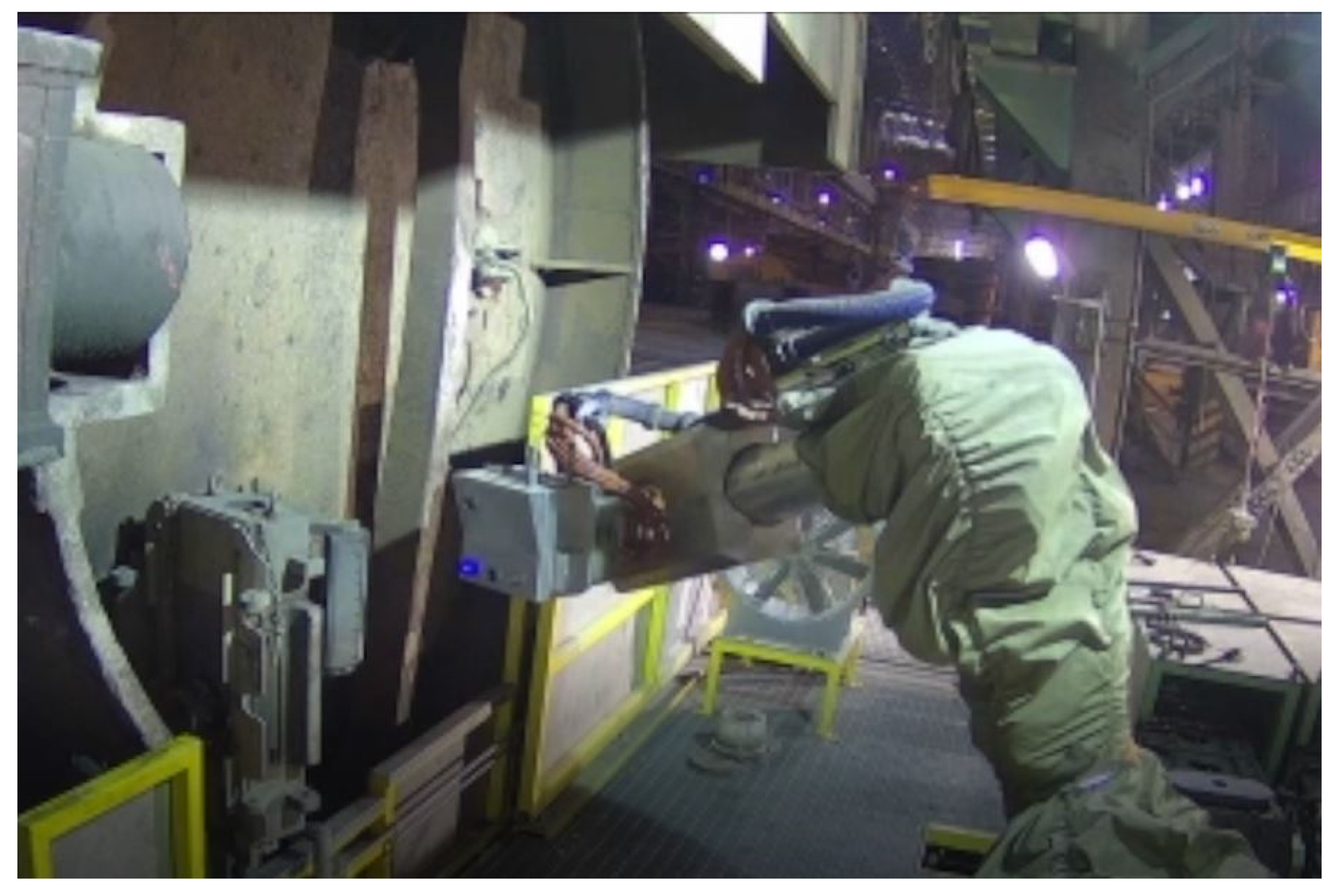
2.2. The Robotic Workstation

A deep analysis of the original maintenance station allowed identifying the main modifications needed to install the robotic workstation. The main environmental factors (e.g., temperature range, presence of dust) and operator needs affected the selection of the components of the robotic cell and of the vision system of the robot.
The central element of the robotic workstation is the industrial robotic arm ABB IRB 7,600,245/3.0 with Foundry plus protection, which is a 6 DOFs manipulator characterized by a weigh of about 1540 Kg and a handling capacity of 245 Kg. The movable platform, where the technical personnel developed the manual maintenance operations, was drastically modified to host the robot and to improve the protection of the workers from high temperatures and accidental contacts with the ladle bottom. Three ad-hoc designed conveyor belts carry the refractory components toward the robot, while some supports hold the oxygen lances and the refractory components (e.g., during mortar application). In order to charge the refractory components on the conveyor belt, and prevent the operator to raise heavy weights, a hoist is used, which is located outside the barriers surrounding the area of the robotic workstation. The hoist is equipped with a manual control panel, which allows its actuation by the operator. Figure 2 provides an overview of the robotic workstation.
The pulpit of the robotic cell is located in an air-conditioned container with two enter/escape doors and one door allowing entrance to the robotic cell only when the robot is inactive. A specific safety key unlocks this door, which must be removed from a panel, and the key removal cuts off the power from all the devices inside the robotic cell, by thus ensuring safe entrance in the robot area for the workers. The container holds a window, which allows the operator applying the mortar on each refractory component without exiting the container. The container also hosts the pulpit of the rotating ladle support, which is a secondary pulpit identical to the one which was already present in the maintenance station before the installation of the robotic workstation. Therefore, all the operations related to the ladle handling, which precede and follow the actual maintenance cycle, are developed by the operators while staying inside the container.
Like the human operators, also the robot needs some tools in order to accomplish the different operations, which are depicted in Figure 3. There are several extraction tools dedicated to the different refractory components, one tool for handling the oxygen lance, one devoted to the removal of the material residues from the nozzle and one tool to spray the graphite on the discharger head. All the tools are stored in a tool warehouse (see Figure 3) and the robot picks and release them from the tools during the operations, according to both pre-defined sequences, established on the basis of the procedure codified by the list of operations reported in Table 1, and to specific indications provided by the technical personnel via the command pulpit.
The vision tool is of particular importance, as it is used for all the preliminary and intermediate inspection operations which are required during the whole maintenance sequence. Such tool consists of a single protective container which incorporates a 2D vision camera IDS UI-5270CP-M-GL (P/N: AB02037) (1/1.8″ 3.45 μm 2056 × 1542 Pixel) (produced by IDS Imaging Development Systems GmbH, Obersulm, Germany) and a 3D laser scanner with blue blade AT Compact Sensor C5-4090CS18-842 (i.e., a 3D sensor with integrated laser line generator manufactured by Automation Technology GmbH, Bad Oldesloe, Germany). The vision tool integrates a wireless receiver connected to a WiFi server located near the robot area and directly connected to the vision PC with a gigabit LAN. The performance of this wireless communication, although not equivalent to a gigabit LAN, is fast enough for the purposes of this application. On the other hand, a fully wireless solution is preferable considering the presence of dirt and dust in the operating environment. The absence of wires also implied the need to embed a battery inside the vision tool, which is automatically recharged when the tool is placed in the tool warehouse. Figure 4 shows the robot while performing one inspection of the opened sliding gate and the blue blade is clearly visible.
The image and 3D scans acquired through the vision system are pre-processed and analyzed through a dedicated software developed in C#, partly exploiting the commercial software library HALCON 13 produced by MVTec Software GmbH, Munich, Germany. Images are denoised, while the 3D cloud provided by the laser scanner are pre-processed to eliminate distortion through the implementation of a standard calibration procedure. A neighbor distance-based algorithm clusters the points of the 3D cloud into different objects and basic elements are recognized to guide the cleaning and replacing operations. For instance, on the undistorted image of the open sliding gate four lateral holes are firstly detected through a pattern matching algorithm looking for circles. Afterwards the center of the fixed plate is identified as the crossing point of the two segments connecting the centers of the couples of the not neighboring holes. A series of regions of interests are then dynamically generated, which allow identification of further reference points in the image. Similar image processing steps are performed on all the images acquired by the vision system in order to identify reference points on all the sections of the sliding gate, which are useful for removal, cleaning and replacement operations of the different components and parts.

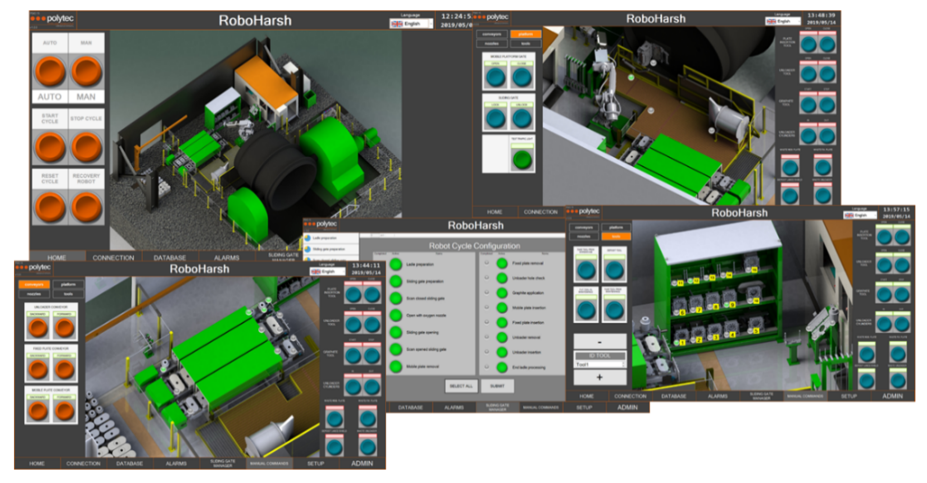
2.3. Human–Machine Interface

An ad-hoc Human-Machine Interface (HMI) was developed to allow a friendly management of the robotic workstation by the technical personnel. Through this HMI, the operator configures the maintenance cycle, controls, executes and overviews all the operations performed by the robot. The interface is accessible through a touch screen placed in the pulpit, while other panels shows the images recorded by the vision tool and the outcomes of the image processing stages. The system records all the performed operations and stores them in a database together with the operator’s unique identifier.
The HMI is organized into different panels for configuration and monitoring of all the phases of the maintenance operations and all the system components, such as depicted in Figure 5, where different panels are shown. The initial “home” window shows a helicopter view of the robotic cell. Clicking on the different areas of the workstation, the corresponding panel of the HMI can be opened. Each panel displays the signals coming from the various components of the cell placed in the concerned area, and the manual commands that can be performed in such area.
For instance, Figure 6 shows the home window together with the panels of the areas of tool warehouse, conveyor belts and movable platform. The robot cycle configuration popup is also shown, which allows selecting the operations sequences to be performed by the robot according to a pre-defined order, and monitoring the progress of the submitted cycles. During the development of some cycles, further popups appear asking for the acknowledgment to develop additional actions. For instance, a confirmation popup is shown before replacing a refractory component.
The vision tool facilitates inspection by the operator; but the operator might also decide to perform visual inspection and/or other manual operations, if he/she is not satisfied by the level of accomplishment achieved by the robot. The panels allow the system to record such decision, so that each manual operation is stored in the database in order to assess system functionality in the long term as well as the full “history” of each maintenance cycle. Each time the operator exits the container or opens its window to perform a manual operation (being it scheduled, such as the mortar application, or not, such as a manual intervention due to unsatisfactory robot performance), the safety system deactivates the robot and the duration of the operation is recorded.
A secondary monitoring system, located outside the cell and composed by four cameras and a video recorder, provides videos of all the operations by also showing them on the monitor inside the pulpit. In this way operators can continuously monitor all the sections of the robotic cells without blind spots. Such surveillance system improves the awareness of the operators concerning what is happening in the whole cell, avoiding them to leave the safe and air-conditioned environment of the pulpit. Moreover, such system supports the remote control of the robotic workstation by the providers during the installation. The provider can remotely overview the operations and directly connect to the workstation through the network, by checking all the relevant parameters and identifying the causes and solutions of eventual problems.

2.4. Methodology for Functional Assessment of the Robotic Workstation

In order to assess the effectiveness of the robotic workstation in developing the different steps of the sliding gate maintenance cycle, the operations reported in Table 1, which are developed by the robot, were grouped into a series of macro-operations (i.e., complex operations possibly composed many elementary operations among the ones reported in Table 1), which are listed in the first column of Table 2. The correspondence between the macro-operations and the elementary operations is identified in the third column of Table 1. Table 1 also shows that all the manual operations implying raising of heavy weights have been eliminated by exploiting the robot or the hoist. The functionality has been assessed during the tests by computing the success rate of each macro-operation, which should be developed by the robot as follows:
s u c c e s s   r a t e o p e r a t i o n = N o   o f   a u t o m a t i c   c o m p l e t i o n s   o f   t h e   o p e r a t i o n N o   o f   t i m e s   t h e   o p e r a t i o n   w a s   d e v e l o p e d .
Other selected functional performance indexes are:
  • Average difference between the time required to complete the manual maintenance operation and the robot-assisted maintenance operation;
  • Percentage reduction of the time of exposure of workers to high temperatures.

2.5. Methodology for Assessment of Impact on Workers of the Robotic Workstation

The assessment of the social impact of the developed robotic station was made by means of a survey and interviews targeting both the solution developers and the operators of the steelworks, which were involved in the test phase. Both target groups made extensive and critical experiences during the innovation development process, based on day-to-day cooperation. The survey content was almost identical for developers and operators.
From a statistical point of view, the number of interviewees is not high (around 20), as the robotic workstation was the outcome of a research project and the first exemplar for this application could only involve the directly concerned people in the steelworks. Due to the prototypical nature of the system, the personnel of the steel shop, which was involved in the research project, needed to be selected based on experience and level of skills on the concerned maintenance operation, in order to get useful suggestions in the design phase, and a sound assessment of the strength and weaknesses during the tests. Therefore, the opinion of one person has a high weight and no statistical representativeness could be claimed. Nonetheless, the aim and the element of novelty of this second part of the assessment was to overcome the limitations of traditional functional assessment developed when commissioning any kind of system, which are usually made by developers and highly qualified technicians aiming at co-designing and verifying that the system properly works. Here the aim was to assess if the intended process of co-creation and social innovation, which was put in place since the beginning of the process, was successful and if the developed system is perceived as an opportunity by the end-users.
In effect, the system also provides a chance to workers, who formerly developed a fully manual operation, to improve their digital skills by shifting their role from “operators” to “supervisors”. To this aim, a full training course and a didactical user manual were developed to provide the operators with the basic notions, which were useful to fully exploit the functionality of the robotic workstation. Furthermore, the degree of co-creation and co-designing the robotic workstation in a mutual learning process of developers and end-users as part of the social innovation process was (quantitatively and qualitatively) analyzed. A survey of the developers and operators conducted by similar questions allowed to compare their impression and assessment of the impact, new working conditions, relevance, acceptance, and training needs of the new technological solution as well as a reflection of the social innovation and co-creation process.

3. Results

3.1. Assessment of the Functionality of the Robotic Workstation

The maintenance cycle was extensively tested for about one year in a real steel shop in concrete operating conditions. The workers were preliminary trained in order to properly manage the workstation, correctly use the HMI and develop all the tasks of their competence. Such tests allowed assessing the actual success rate of each macro-operation in standard conditions, by also showing that a smooth concatenation of the different operations is achieved. Table 2 summarizes the outcomes of the tests.
In case of unsuccessful completion of the operation by the robot, the possibility to manually implement the operation is always available. This is an important aspect of the human–robot interaction, ensuring the quality of the performance and showing that human intervention has to be an integrated part of new technological solutions. Thus, the impact of eventual robot failures on the whole maintenance cycle is limited by a continuous human monitoring and interaction, when required, which ensures both deep involvement of the personnel, in perfect analogy to the manual procedure, and full development of each stage. In effect, no accidents or near miss in both maintenance procedure and ladle operation were observed during the test phase.
Noticeably, the performance index provided by Equation (1) classifies an operation as “successful” when it is fully implemented through the robot. Partial completion (where applicable) of operations is classified as a “failure”, due to the difficulty to assess the degree of such completion. However, this assessment approach follows a “worst-case philosophy,” by attributing a considerable weight to the need for the operator to exit the pulpit but neglecting the partial contribution to the operation provided by the robot. For instance, the unsuccessful completion of the tap hole cleaning with the oxygen lance implies that an operator needs to exit the pulpit in order to complete the cleaning, which is surely an inconvenience. However, the previous attempt done by the robot to perform the same operation leads to a partial removal of the residues. Therefore, the efforts spent by the operator to complete the cleaning and the time spent in proximity of the hot ladle bottom are lower with respect to the manual procedure, as the robot develops part of the work. To sum up, even in this case the robot relieves the efforts of the operators without any negative impact on the final outcome of the maintenance procedure.
The average time needed to complete the whole procedure is slightly higher than the time required to complete the manual procedure, but in the final tests such difference was around 5 min, which was considered tolerable by the technical personnel. It must be underlined that most steelworks hold at least two ladle maintenance stations, often more than two, although such number depends on the number of used ladles. Therefore, the interval between two ladle maintenance operations, which are subsequently developed on the same station, is higher than 35 min.
As far as the time of exposure of the workers to high temperatures is concerned, if all the automatic operations are successful, such time is reduced by 80%, while in the worst cases (i.e., for instance, when the cleaning of the tap hole is not completed by the robot and the operators needs to exit the pulpit) it is reduced by 50%.

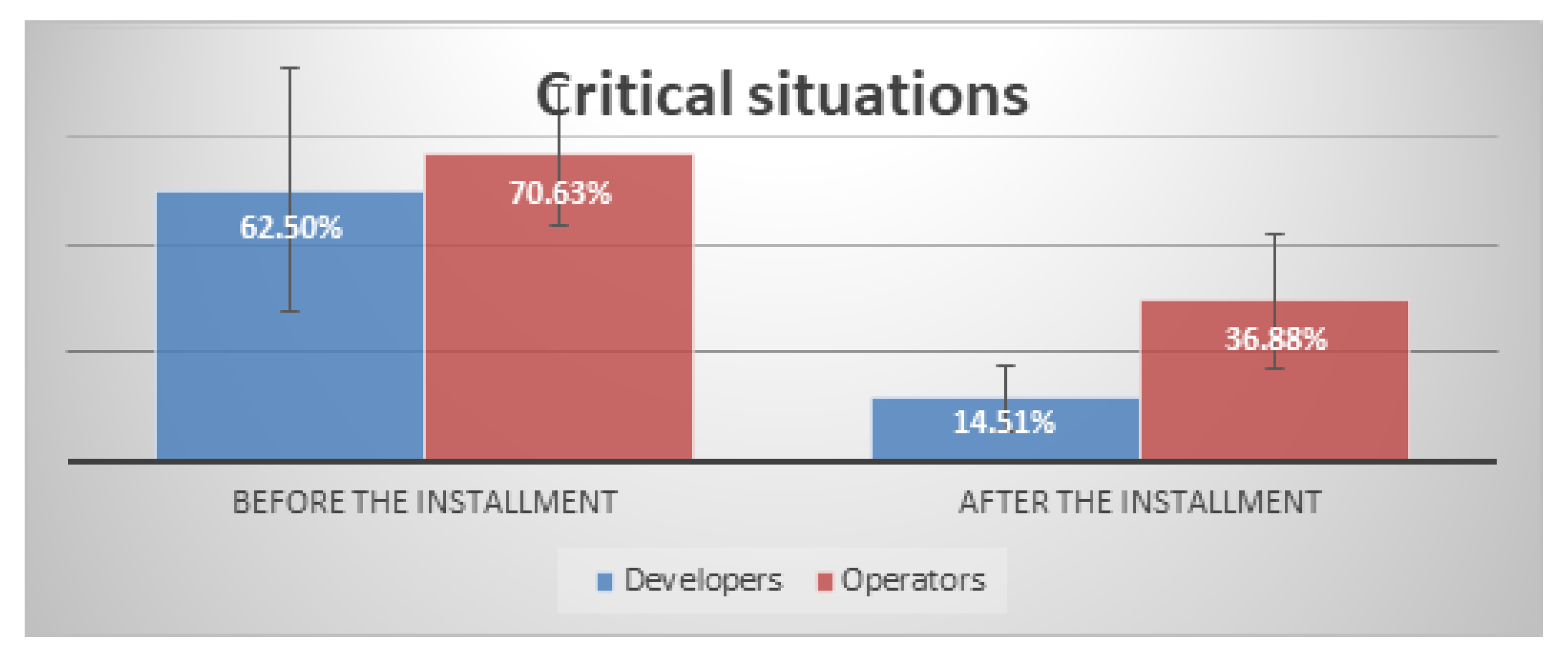
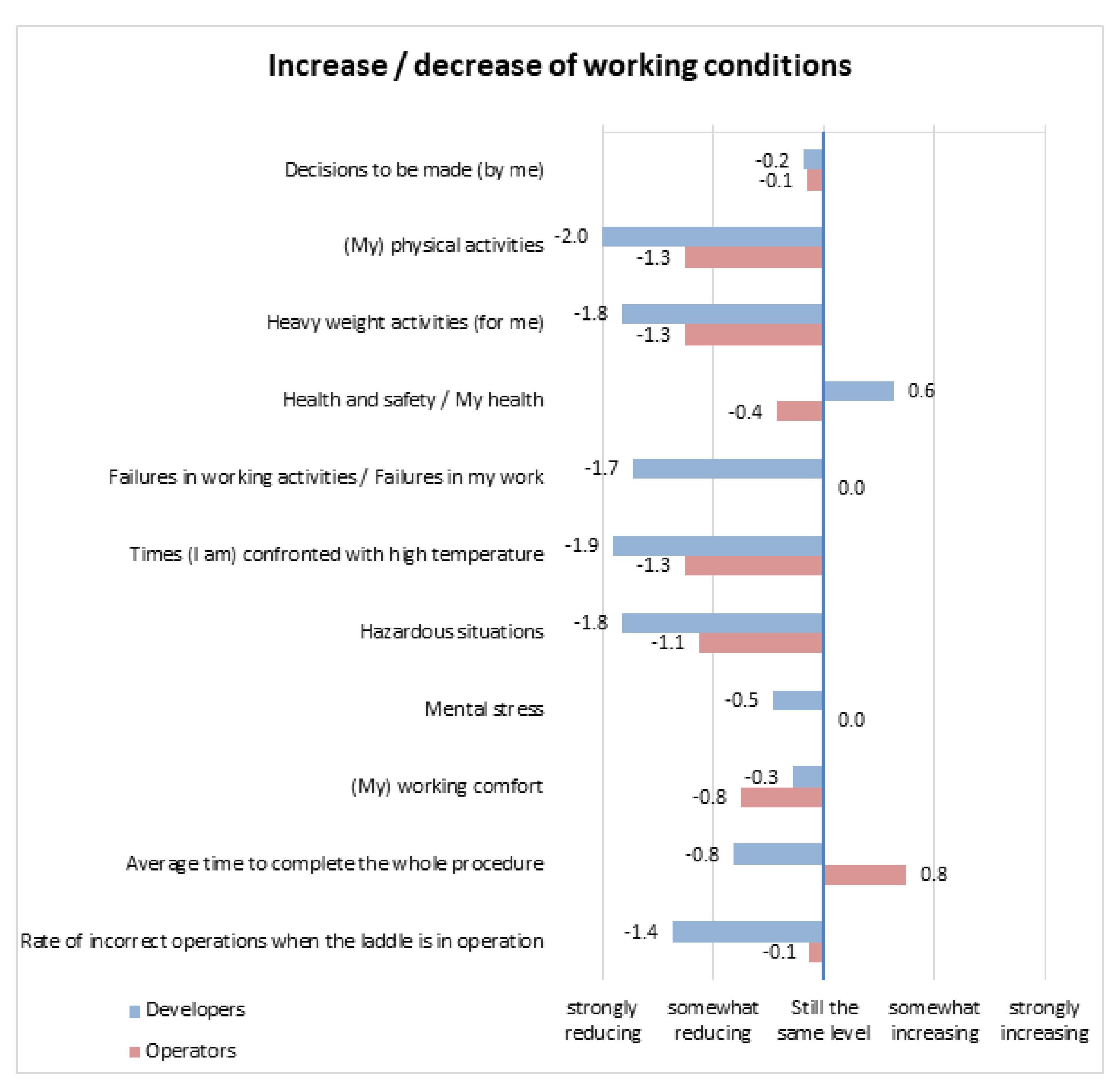
3.2. Assessment of Social Impact

To assess the social impact and innovation process the perspective of the developers and operators were collected and compared. An important general difference between the interviewed operators and the developers is their (preliminary) knowledge of robotic assistance. While the developers already had domain-related knowledge derived from previous experiences in the field, only 25% of the operators held basic notions on robotic solution and human–robot cooperation and, for 88% of them this was the first practical work experience in a robotic environment.
All the participants agree on the fact that robotic assistance increases health and safety by reducing physical, heavy weight activities, exposure to high temperatures and hazardous situations. As shown in Figure 6, critical situations for health and safety decreased drastically from 63% to 15% for the developers, and from 71% to 37% for the operators.
Figure 7 shows the perceived direct impact (based on the averages of a scale from −2 to +2) of the robotic workstation on the working conditions. Developers and operators state that the robotic cell reduces physical and heavy weight activities, hazardous and high temperature situations, failures and incorrect operations (health and safety in general are seen more critical by the operators). Although there are new decisions at the workplace expected by the developers, a slight decrease of the overall number of decisions is estimated. Mental stress is not expected to increase, but the working comfort is a bit decreased (e.g., mainly by the new requirements of the robot). The operators expect that failure reduction and incorrect operations will be still at the same level, while the developers are more optimistic on this aspect. This is in line with the relevant experience of the operators in developing the manual maintenance procedure. They also correctly estimated the slight extension of the procedure duration, which was verified within the technical assessment, although it was considered tolerable.
Increased health and safety are the main outcome of the new division of tasks between robot and operators. As shown in Figure 7 and Figure 8, developers state a substantial reduction of workload and they somewhat agree to the thesis that the new solution makes work more interesting and increases job satisfaction. The operators are in general of the same opinion, but to a lower degree.
Concerning the professional development, the questionnaires underlined that new skills are required. This is especially stressed by the operators. Training for robot assistance could be integrated in existing trainings schemes (but has to be clearly exposed). The operators claim that the recent training measures could be extended and new skills and training demands should be met by a mix of methods (as shown in Figure 9): Learning on the job, training by the robot providers and general training courses are all of high relevance. Beside the general importance, the developers prefer learning on the job while the operators prioritize training by the system providers.
The social innovation process was finally evaluated as well. In this case, developers and operators do come to almost the same conclusions positive conclusions. The operators were sufficiently involved in the development process, their opinions were heard, the developers took up their suggestions (this was underlined by the fact that 68% of the suggestions of the operators were taken up by the developers), and the management of the company was supporting the operator involvement (see Figure 10).
A difference appears concerning the information flow: While the developers overall think that the end users got all the relevant information, half of the operators claim that they did not got all the information needed.
The information deficit claimed is also underlined by a deficit of communication and cooperation structures stated by the operators. More leeway for action-taking and decision making is rated as average. However, for operators and developers, management instructions and new organizational measures supported the workstation development to a higher extent. Overall, according to the developers, there was a high integration of users/operators, stakeholders in the innovation (co-creation) process, depending on the stage and subject of development. The operators testified the developers’ statement, by mainly a monthly or weekly involvement. It must be underlined that the interviewed developers were involved in the development of different components of the robotic workstation and the involvement of the operators was not the same for the different components. For instance, they were deeply involved in design of robotic cell layout and of mechanical components, in programming of the robot movements and in HMI development, while their involvement was lower as far as the database and the artificial vision algorithms are concerned, although they provided useful advices even in these cases.

4. Discussion

The installation of the robotic workstation led to considerable benefits in terms of improved health and safety conditions of the workplace. Such as shown in Table 1, after the installation of the robotic workstation among the 39 elementary operations composing the original manual maintenance procedure, only eight operations are still manual and need to be developed outside the air-conditioned pulpit. Two further operations concerning mortar application on the new refractory components prior to placement on the sliding gate are still manual, but they are surely not cumbersome and can be developed inside the pulpit by opening a window. On the other hand, uncomfortable and risky operations, such as the tap hole opening through the oxygen lance, which is depicted in Figure 11, are in most cases fully developed by the robot.
To sum up, with an optimal human–robot task division:
  • The most hazardous operations (e.g., the tap hole opening through the oxygen lance) are performed by the robot;
  • One hundred percent of the operations implying raising of heavy weights are conducted by the robot or by the hoist equipping the workstation;
  • A drastic decrease of operators’ exposure to high temperatures with respect to the manual procedure is observed.
The pursued assessment; however, aimed not only at an objective evaluation of the functional efficiency and technical reliability of the developed system, but also at assessing the end-users’ integration and perception of the system, based on the principle that workers’ experience and acceptance is a pre-requisite for effective development and wide and successful deployment of any innovation within the target industrial context.
Based on such new understanding and paradigm of innovation, the development of the robot and its human–robot interface was done in a co-creation process between technological developers, users/operators and stakeholders of the steelworks, where the robotic workstation was installed. Therefore, the technological solution for a modified and re-organized improvement of the working environment and working conditions integrated the experience of the operators. Their workplace and operational practices-based skills and knowledge were included in the development process of the technological solution. This procedure contributed to improving not only the overall performance of the new robotic cell but also the acceptance of this new solution by the target end-users.
The assessment pursued through interviews and a survey show that the social innovation process was successfully accepted, implemented and conducted: Developers and operators underlined the mutual co-creation with a high participation of end users (operators and foremen), managers, HR and R&D stakeholders, robot developers and project researchers. The user involvement was high (from daily, weekly and monthly involvement), their suggestions were heard, and taking up two out of three suggestions is showing the evidence of the workplace experience. The management and new organization measures supported the innovation development. Nevertheless, more information and communication within the development process is an important and improvable element of the innovation process.
To sum up, the development of this robotic workstation, representing the first attempt of human–robot cooperation in the harsh context of the steel shop, implemented a joint optimization of technology, human and organization. All dimensions were equally considered in an economic; not in a way that organization and people have to follow technology. The principles of good digital work, which are described in [39], were considered in the development of this robotic system, by making it efficient and economic-effective:
  • Complementarity of human and robot is given in a new task division;
  • Adaption of specific skills, experiences of the operators were taken up in the co-creation process;
  • The holistic perspective covered the completeness of tasks, hazardous and load-reducing effects took place;
  • The robotic station is a small self-organizing socio-technical system, allowing scope of decision in self-managed teams, at the workplace;
  • Participation and involvement of users took place;
  • New operational tasks with new multiple (digital) skills were created, promoting multiple skills for supervising the maintenance process.
These guiding principles of “Good Digital Work” are expected to jointly increase system performances and users’ acceptance.
The quantitative assessment of the system efficiency and functionality find a confirmation in the perception of the people who were involved in the development and test of the system. Both developers and operators affirm the general acceptance, the usefulness of the workstation for the job, by perceiving a reduction of hazardous situations, high temperature exposure and heavy weight activities and stating that the maintenance procedure became easier, more interesting and less cumbersome.
The proposed investigation; therefore, underlines the needed human-centered approach in a common technological and social innovation process (Industry 5.0), by highlighting the benefits of such approach. Furthermore, it stresses the still remaining relevance of human expertise and action within digitalized and automated production and maintenance processes, often neglected in some Industry 3.0 (Automation) and Industry 4.0 (Digitalization, Internet of Things) predictions [40,41,42].
Clearly the proposed solution cannot be transferred outside the steel sector but is transferable throughout the whole steel sector in any steelmaking site. The robotic workstation can be adapted to all sliding gates types (which are around 10), although the related cost for adaptation to be sustained by the system developers is estimated as ranging from 20.000 to €100.000. A preliminary transferability analysis was also developed concerning a widely adopted type of sliding gate produced by Radex-Heraklith Industriebeteiligungs AG (RHI). The main difference between the RHI sliding gate and the one considered in the present work, as far as the implementation of the robotic cell is concerned, lies in the fact that the RHI sliding gate can be unlocked by moving a big pin. This operation can be easily performed by the robot through a hydraulic cylinder. With the sliding gate selected by the steelworks, where the robotic cell was firstly implemented, this operation is still manually performed by the operator, which removes the safety pins and opens the door through a long leverage. In this preliminary transferability analysis, a comparison was made by highlighting both the possibility to automate each operation according to the list provided in Table 1 and the need for the operator to exit the pulpit in order to perform some manual task. Being a preliminary exercise, this transferability analysis was developed testing the robotic cell on an artificial setup, where all the RHI sliding gate was present and without implementing specific tools for handling it. According to such analysis, by using the RHI sliding gate operations No 13, 14, 32 and 36 could be automatically developed, by thus halving the number of operations, which imply the need for the operator to exit the pulpit and; therefore, by further reducing the time of exposure to high temperatures. Benefits are also expected in terms of reduction of the time required to develop the whole maintenance cycle.

5. Conclusions

The paper presented the outcomes of an extensive field testing of a robotic workstation which was specifically designed to support human operators of the steel shop in the maintenance of the ladle sliding gate. The system represents one of the first attempts to implement a human–robot cooperative environment in such a harsh and complex workplace and shows the following main innovative features:
  • It derives from a co-design process, where end-users were involved since the initial stages and significantly contributed to the analysis and conceptualization of the new system, through a human-centered approach in a common technological and social innovation process.
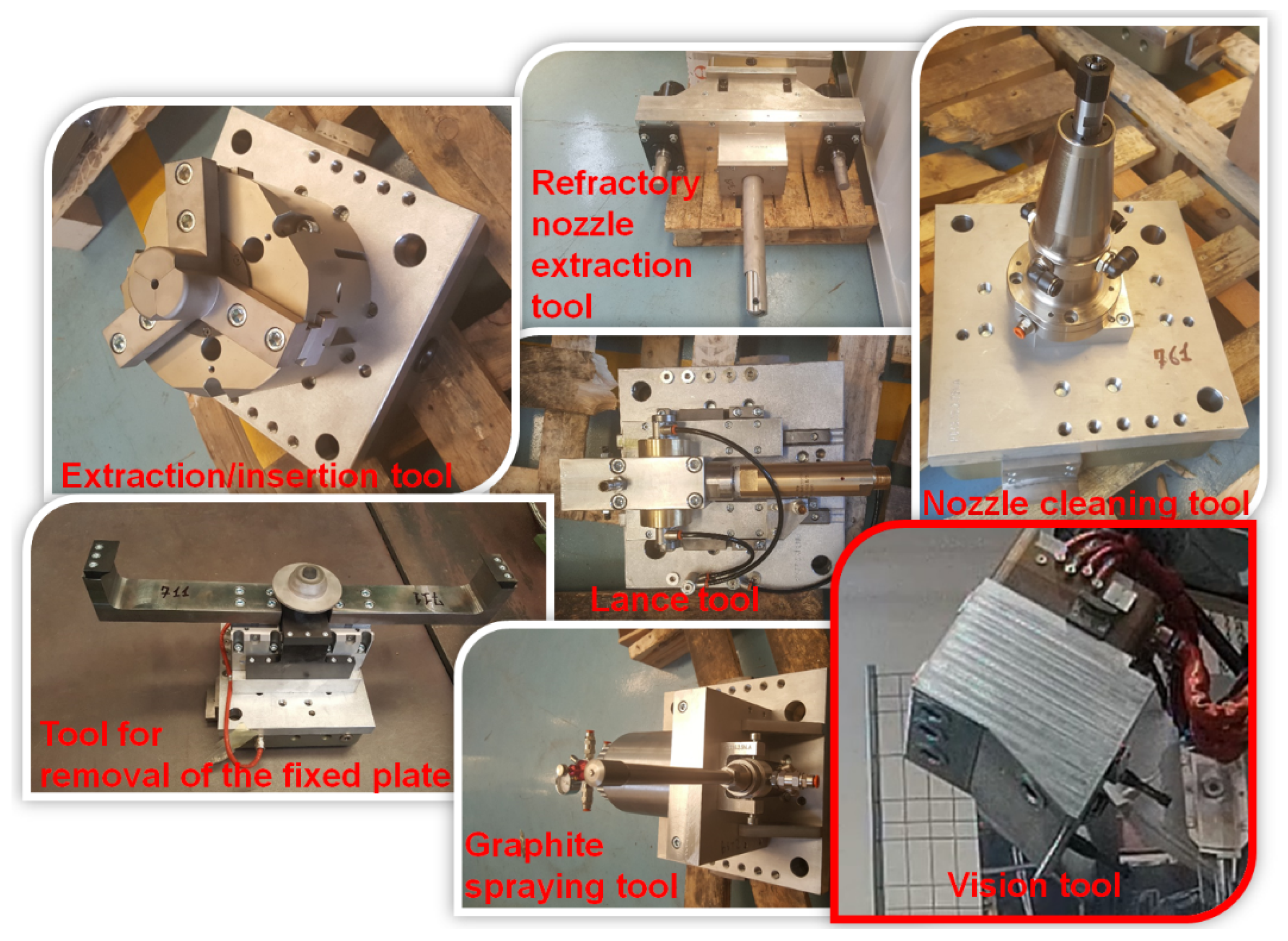
  • It includes a series of tools for developing different tasks, among which a vision tool exploiting artificial vision for inspection operations and a user-friendly HMI;
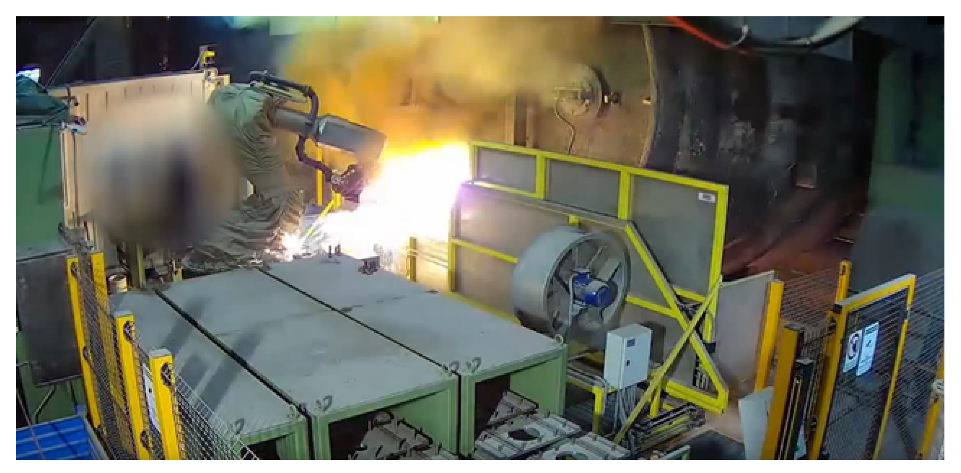
  • It significantly improves workers’ health and safety conditions in terms of elimination of cumbersome operations and reduced exposure to sparks and high temperatures;
  • It is designed in a way that keeps technicians deeply involved in the maintenance procedures although relieving most physical efforts, as they must supervise the robot operations, develop some manual steps and eventually complete some operations, in case the robot does not successfully carry them out;
  • It promotes upskilling of the technical personnel, especially concerning digital skills, by shifting their role from “manual operators” to “supervisors.” To this aim, a specific training course was designed together with the system and exploiting the experience of the personnel which was involved in the test phase;
  • As a consequence of what above, the system performance were assessed through both quantitative functional indicators and interviews to operators.
Ongoing work mostly focuses on transferring the proposed solutions to other types of sliding gate, in order to fully deploy the proposed solution in the steel sectors. First results in this direction are very promising. Future work will concern a joint adaptation of the robotic workstation and of the sliding gate, namely the design of specific sliding gates which are designed to implement robotic maintenance procedure. This solution will allow for simplifying the robotic cell by reducing the number of tools to be handled by the robot and the number of operations which require the human intervention, especially if they are developed nearby the ladle and outside the air-conditioned command pulpit.

6. Patents

The described robotic workstation has been patented in Italy and the European patent request is still pending. The Italian Patent No 102017000106914 is entitled “Sistema semi-automatizzato per la manutenzione in sicurezza di un cassetto di una siviera e relativo metodo di manutenzione”.

Author Contributions

Conceptualization, V.C., A.J.S. and M.S.; methodology, V.C., A.J.S. and M.S.; software, V.C., R.M. and M.S.; validation, V.C., R.M. and M.S.; formal analysis, V.C., A.J.S. and M.S.; investigation, V.C., R.M., A.J.S. and M.S.; resources, V.C. and M.S.; data curation, V.C., A.J.S., M.S. and L.R.; writing—original draft preparation, V.C. and A.J.S.; writing—review and editing, R.M., M.S. and L.R.; visualization, R.M. and M.S.; supervision, V.C., M.S. and L.R.; project administration, V.C., M.S. and L.R.; funding acquisition, V.C. and M.S. All authors have read and agreed to the published version of the manuscript.

Funding

This research was funded by the European Union through the Research Fund for Coal and Steel (RFCS), Grant Agreement No 709553.

Institutional Review Board Statement

Not applicable.

Informed Consent Statement

Not applicable.

Data Availability Statement

No new data were created or analyzed in this study. Data sharing is not applicable to this article.

Acknowledgments

The work described in this paper was developed within the project entitled “Robotic workstation in harsh environmental conditions to improve safety in the steel industry,” (RoboHarsh Grant Agreement No 709553), which has received funding from the Research Fund for Coal and Steel of the European Union. The sole responsibility of the issues treated in this paper lies with the authors; the Commission is not responsible for any use that may be made of the information contained therein.

Conflicts of Interest

The authors declare no conflict of interest.

References

  1. Colla, V.; Pietrosanti, C.; Malfa, E.; Peters, K. Environment4.0: How digitalization and machine learning can improve the environmental footprint of the steel production processes. Materiaux et Téchniques 2021, in press. [Google Scholar]
  2. Miśkiewicz, R.; Wolniak, R. Practical Application of the Industry 4.0 Concept in a Steel Company. Sustainability 2020, 12, 5776. [Google Scholar] [CrossRef]
  3. Branca, T.A.; Fornai, B.; Colla, V.; Murri, M.M.; Streppa, E.; Schröder, A.J. The challenge of digitalization in the steel sector. Metals 2020, 10, 288. [Google Scholar] [CrossRef] [Green Version]
  4. Akyazi, T.; Oyarbide, A.; Goti, A.; Gaviria, J.; Bayon, F. Creating a roadmap for professional skills in industry 4.0. Hydrocarb. Process. 2020, 99, 11. [Google Scholar]
  5. González-Ciordia, B.; Fernández, B.; Artola, G.; Muro, M.; Sanz, Á.; López de Lacalle, L.N. Failure-Analysis Based Redesign of Furnace Conveyor System Components: A Case Study. Metals 2019, 9, 816. [Google Scholar] [CrossRef] [Green Version]
  6. Salcedo-Hernández, J.; Rivas-Perez, R.; Sotomayor-Moriano, J. Design of a Robust H2 State Feedback Temperature Controller for a Steel Slab Reheating Furnace. Appl. Sci. 2020, 10, 1731. [Google Scholar] [CrossRef]
  7. Saparrat, M.; Monti, F.; Ibarra, J. AI Application to melting temperature prediction in an electric arc furnace. In Proceedings of the AISTech2020 Iron and Steel Technology Conference; Association for Iron and Steel Technology, Cleveland, OH, USA, 31 August–3 September 2020; Volume 1, pp. 526–532. [Google Scholar] [CrossRef]
  8. Ganesh, H.S.; Edgar, T.F.; Baldea, M. Model Predictive Control of the Exit Part Temperature for an Austenitization Furnace. Processes 2016, 4, 53. [Google Scholar] [CrossRef] [Green Version]
  9. Deshpande, N.; Ortiz, J.; Sarakoglou, I.; Semini, C.; Tsagarakis, N.; Brygo, A.; Fernandez, J.; Frigerio, M.; Saccares, L.; Toxiri, S.; et al. Next-generation collaborative robotic systems for industrial safety and health. WIT Trans. Built Environ. 2018, 174, 187–200. [Google Scholar] [CrossRef]
  10. Demetika, P.; Ferrari, R.; Galasso, L.M.; Romano, F. Robotic system for a “zero-operator” continuous casting floor. In Proceedings of the AISTech 2014 The Iron and Steel Technology Conference, Indianapolis, IN, USA, 5–8 May 2014; Volume 3, pp. 3481–3486. [Google Scholar]
  11. Hansert, P.; Stech, R.; Quant, M. Performance experience of the MultiROB at BSW—How safety, productivity and accuracy go hand in hand. Iron Steel Technol. 2016, 13, 70–76. [Google Scholar]
  12. Meisel, J.; Pfeil, S.; Prinz, G.; Hugel, M.; Priesner, A.; Scheidegger, R. Experience and evolution after 10 years of robotics in continuous casting technology. In Proceedings of the 8th European Continuous Casting Conference ECCC, Graz, Austria, 23–26 June 2014. [Google Scholar]
  13. Lee, S.-H.; Yoon, D.-H.; Choi, S.; Newkirk, J. StrapMaster: A robotic band-strapping system. In Proceedings of the IEEE International Conference on Automation Science and Engineering CASE 2012, Seoul, Korea, 20–24 August 2012; pp. 561–563. [Google Scholar] [CrossRef]
  14. Gerstorfer, G.; Keplinger, T.; Priesner, A.; Sedivy, C.; Traxinger, H.; Voraberger, B.; Watzinger, S. Robotics applications continuously enancing safety in melt shops. In Proceedings of the 8th European Oxygen Steelmaking Conference EOSC 2018, Taranto, Italy, 10–12 October 2018. [Google Scholar]
  15. Egger, M.W.; Priesner, A.; Lehner, J.; Nogratnig, H.; Lechner, H.; Wimmer, G. Successful revamping of sublance manipulators for the LD converters at Voestal-pine Stahl Gmbh. In Proceedings of the AISTech 2014 The Iron and Steel Technology Conference, Indianapolis, IN, USA, 5–8 May 2014; Volume 3, pp. 973–980. [Google Scholar]
  16. Soltani, E. An investigation on continuous steel slabs casting line and mechanical design of a 3R robot for sampling from melting arc furnaces. Adv. Mater. Res. 2010, 83–86, 31–35. [Google Scholar] [CrossRef]
  17. Schwarzbach, L. At the Lech Steelworks, a robot takes samples from ready-to-pour liquid steel: Well measured. Stahl Eisen 2014, 134, 50–51. [Google Scholar] [CrossRef]
  18. Sedano, E.; Baños, R.; Zanelli, U. Safe slag and liquid steel handling. In Proceedings of the AISTech2020 Iron and Steel Technology Conference; Association for Iron and Steel Technology, Cleveland, OH, USA, 31 August–3 September 2020; Volume 1, pp. 593–601. [Google Scholar] [CrossRef]
  19. Visentini, I.; Demetlika, P.; Martin, M.; Ardesi, A. Q-robot ROLL: Vision-based automatic deburring robot for cold billets. Iron Steel Technol. 2016, 13, 142–147. [Google Scholar]
  20. Fernández, B.; González, B.; Artola, G.; López de Lacalle, N.; Angulo, C. A Quick Cycle Time Sensitivity Analysis of Boron Steel Hot Stamping. Metals 2019, 9, 235. [Google Scholar] [CrossRef] [Green Version]
  21. Wang, X.; Xue, L.; Yan, Y.; Gu, X. Welding Robot Collision-Free Path Optimization. Appl. Sci. 2017, 7, 89. [Google Scholar] [CrossRef]
  22. Laudante, E.; Greco, A.; Caterino, M.; Fera, M. Human–Robot Interaction for Improving Fuselage Assembly Tasks: A Case Study. Appl. Sci. 2020, 10, 5757. [Google Scholar] [CrossRef]
  23. Yang, H.; Baradat, C.; Krut, S.; Pierrot, F. An agile manufacturing system for large workspace applications. Int. J. Adv. Manuf. Tech. 2016, 85, 25–35. [Google Scholar] [CrossRef] [Green Version]
  24. Pauliková, A.; Gyurák Babeľová, Z.; Ubárová, M. Analysis of the Impact of Human–Cobot Collaborative Manufacturing Implementation on the Occupational Health and Safety and the Quality Requirements. Int. J. Environ. Res. Public Health 2021, 18, 1927. [Google Scholar] [CrossRef]
  25. Coradeschi, S.; Saffiotti, A. Symbiotic robotic systems: Humans, robots, and smart environments. IEEE Intell. Syst. 2006, 21, 82–84. [Google Scholar] [CrossRef]
  26. Colim, A.; Faria, C.; Cunha, J.; Oliveira, J.; Sousa, N.; Rocha, L.A. Physical Ergonomic Improvement and Safe Design of an Assembly Workstation through Collaborative Robotics. Safety 2021, 7, 14. [Google Scholar] [CrossRef]
  27. European Commission Directorate-General for Research and Innovation. Industry 5.0: Towards a Sustainable, Human-Centric and Resilient European Industry; R&I Paper Series, Policy Brief; Publications Office of the European Union: Luxembourg, 2021; pp. 1–48. Available online: https://op.europa.eu/en/publication-detail/-/publication/468a892a-5097-11eb-b59f-01aa75ed71a1/ (accessed on 15 April 2021).
  28. Kohlgrüber, M.; Schröder, A.; Bayón Yusta, F.; Arteaga Ayarza, A. A new innovation paradigm combining technological and social innovation. Materiaux et Téchniques 2019, 107, 107. [Google Scholar] [CrossRef]
  29. Kohlgrüber, M.; Schröder, A. Innovation reloaded. The social character of digitalisation in industry. In Atlas of Social Innovation: 2nd Volume: A World of New Practices; Howaldt, J., Kaletka, C., Schröder, A., Zirngiebl, M., Eds.; Oekom Verlag: München, Germany, 2019. [Google Scholar]
  30. Veiga Almagro, C.; Lunghi, G.; Di Castro, M.; Centelles Beltran, D.; Marín Prades, R.; Masi, A.; Sanz, P.J. Cooperative and Multimodal Capabilities Enhancement in the CERNTAURO Human–Robot Interface for Hazardous and Underwater Scenarios. Appl. Sci. 2020, 10, 6144. [Google Scholar] [CrossRef]
  31. Dannapfel, M.; Bruggaräf, P.; Bertam, S.; Förstmann, R.; Riegauf, A. Systematic planning approach for heavy-duty human-robot cooperation in automotive flow assembly. Int. J. Electr. Electron. Eng. Telecommun. 2018, 7, 51–57. [Google Scholar] [CrossRef]
  32. Gopinath, V.; Johansen, K.; Derelöv, M.; Gustafsson, Å.; Axelsson, S. Safe Collaborative Assembly on a Continuously Moving Line with Large Industrial Robots. Robot CIM Int. Manuf. 2021, 67, 102048. [Google Scholar] [CrossRef]
  33. Sadik, A.R.; Urban, B. Flow Shop Scheduling Problem and Solution in Cooperative Robotics—Case-Study: One Cobot in Cooperation with One Worker. Future Internet 2017, 9, 48. [Google Scholar] [CrossRef] [Green Version]
  34. Ryu, H.; Jin, M.; You, K.-S.; Choi, C. Development of refractory brick construction robot in steel works. In Proceedings of the IEEE International Conference on Automation Science and Engineering CASE 2012, Seoul, Korea, 20–24 August 2012; pp. 796–801. [Google Scholar] [CrossRef]
  35. Ventura, R. Two faces of human–robot interaction: Field and service robots. Mech. Mach. Sci. 2014, 20, 177–192. [Google Scholar] [CrossRef]
  36. Colla, V.; Matino, R.; Faes, A.; Schivalocchi, M.; Romaniello, L.; Schröder, A.; Zoppirolli, A. A robot performs the maintenance of the ladle sliding gate. Stahl Eisen 2019, 139, 44–47. [Google Scholar]
  37. Colla, V.; Matino, R.; Faes, A.; Romaniello, L.; Schröder, A. Robot-assisted replacement of the refractory components of the ladle sliding gate in a steel shop. In Proceedings of the 10th European Metallurgical Conference EMC 2019, Dusseldorf, Germany, 23–26 June 2019; Volume 4, pp. 1441–1454. [Google Scholar]
  38. Colla, V.; Schroeder, A.; Buzzelli, A.; Abbà, D.; Faes, A.; Romaniello, L. Introduction of symbiotic human-robot-cooperation in the steel sector: An example of social innovation. Materiaux et Techniques. 2017, 105, 5–6. [Google Scholar] [CrossRef]
  39. Dregger, J.; Niehaus, J.; Ittermann, P.; Hirsch-Kreinsen, H.; Ten Hompel, M. The digitization of manufacturing and its societal challenges: A framework for the future of industrial labor. In Proceedings of the 2016 IEEE International Symposium on Ethics in Engineering, Science and Technology, ETHICS 2016, Vancouver, BC, Canada, 13–14 May 2016. Art. No. 7560045. [Google Scholar] [CrossRef]
  40. Atkinson, R.D.; Wu, J.J. False Alarmism: Technological Disruption and The US Labor Market; Information Technology & Innovation Foundation ITIF: Washington, DC, USA, 2017; pp. 1850–2015. Available online: https://itif.org/publications/2017/05/08/false-alarmism-technological-disruption-and-us-labor-market-1850-2015 (accessed on 15 April 2021).
  41. Autor, D.; Salomons, A. Is Automation Labor-Displacing? Productivity Growth, Employment, and the Labor Share; National Bureau of Economic Research: Cambridge, MA, USA, 2018; Available online: https://www.nber.org/papers/w24871 (accessed on 15 April 2021).
  42. Bauer, W.; Vocke, C. Work in the Age of Artificial Intelligence—Challenges and Potentials for the Design of New Forms of Human-Machine Interaction. Adv. Intell. Syst. 2020, 961, 493–501. [Google Scholar] [CrossRef]
Figure 1. (a) the ladle during transport to the maintenance station in the steel shop; (b) the sliding gate adopted in the considered application.
Metals 11 00647 g001
Figure 2. Overview of the robotic cell.
Metals 11 00647 g002
Figure 3. Overview of the different tools handled by the robot: The vision tool is highlighted in red.
Metals 11 00647 g003
Figure 4. The robot inspects the opened sliding gate by means of the vision tool.
Metals 11 00647 g004
Figure 5. HMI of the robotic workstation: “Home” window, panels of conveyor belts, tools warehouse and platform and panel for configuration of the maintenance cycle.
Metals 11 00647 g005
Figure 6. Perceived impact of the robotic workstation on critical situations (percentage of answers, the lines are showing the standard deviation of the answers).
Metals 11 00647 g006
Figure 7. Overview of the perceived impact of the robotic cell on the working conditions. (Average of the answers within a 5-point scale, from −2 strongly and −1 somewhat disagree over 0 do not agree or disagree to +1 somewhat agree to +2 strongly agree).
Metals 11 00647 g007
Figure 8. Overview of the perceived impact of the robotic cell on the working conditions. (Average of the answers within a 5-point scale, from −2 strongly and −1 somewhat disagree over 0 do not agree or disagree to +1 somewhat agree to +2 strongly agree).
Metals 11 00647 g008
Figure 9. Preferences on training approaches (percentage of answers).
Metals 11 00647 g009
Figure 10. Perceived involvement in the social innovation process. (Average of the answers within a 5-point scale, from −2 strongly and −1 somewhat disagree over 0 do not agree or disagree to +1 somewhat agree to +2 strongly agree).
Metals 11 00647 g010
Figure 11. The robot opens the tap hole using an oxygen lance.
Metals 11 00647 g011
Table 1. List of elementary operations composing the maintenance of the ladle sliding gate and how they are handled in the robotic workstation. For operations which are developed through the robot, the corresponding macro-operation is provided in the third column. The operations which remain manual after the installation of the robotic cell and are developed outside the pulpit are highlighted in yellow. Manual operations developed inside the pulpit are highlighted in green.
Op. NoDescription of the Elementary OperationDevelopment in the Workstation
1Preparation of the new fixed and mobile plate to be replacedHoist + conveyor belts
2Preparation of the new refractory nozzle to be replaced
3Location of the ladle on the maintenance station and lockingAutomated through secondary pulpit
4Connection of hydraulic hoses, screwing the links and descending into the pit (interlock release needed). Extraction of the piston blocking the ladle rotation systemMANUAL (outside pulpit)
5120° rotation of the ladleAutomated through secondary pulpit
6Movement of the platform so that it is close to the ladle bottom
7Pulling out the connecting pin of the opening mechanism of the sliding gate
8Rotation of the ladle from 120° to 90°.
9Locking the rotation at 90° with a cylindrical pivot
10Further movement of the platform so that the ladle bottom is reachable by the operators
11Opening of the tap hole through an oxygen lanceROBOT: Tap hole opening
12Cleaning of tap hole with bent nozzleROBOT: Tap hole cleaning
13Removal of security cotter pins from pivots, which ensure the closure of the sliding gateMANUAL (outside pulpit)
14Opening of sliding gate springs, shutter unlocking and sliding gate opening through a lever mechanism
15Picking of the mobile plateROBOT: removal of the mobile plate
16Replacement of the mobile plate
17Removal of fixed plateROBOT: Removal of the fixed plate
18Verification of size and contour of the discharger hole, to decide whether the cleaning operation is sufficient or replacement is needed.ROBOT: inspection
19Extraction of the refractory nozzle, which is laid down in the unloading areaROBOT: extraction of the nozzle
20Air cleaning of the refractory nozzle locationMANUAL (outside pulpit)
21Verification of the cleanliness of the nozzle locationROBOT inspection
22Picking of the mobile plateROBOT: insertion of the mobile plate
23Insertion of the mobile plate
24Picking of the new refractory nozzle ROBOT: insertion of the nozzle
25Application of the mortar on the discharger and its collarMANUAL (in pulpit)
26Insertion of the new refractory nozzle in its locationROBOT: insertion of the nozzle
27Cleaning of the area involved in the coupling of nozzle/internal plate from excess mortarMANUAL (outside pulpit)
28Verification of the planarity of the fixed plate in its final locationROBOT: inspection
29Spraying of graphite on the nozzle headROBOT Graphite application
30Application of a uniform layer of mortar on the fixed plat.MANUAL (in pulpit)
31Location of the fixed plate on the sliding gateROBOT: insertion of the fixed plate
32Closure of the sliding gate, brackets clamping through a leverism, insertion of pins and safety cotter pinsMANUAL (outside pulpit)
33Movement of the platform away from the ladleAutomated through secondary pulpit
34Check of the cleanliness of the tapping hole through a buffer tubeROBOT: inspection
35120° ladle rotationAutomated through secondary pulpit
36Insertion of security cotter pins for sliding gate opening command, check of proper functioning of the sliding gate and check of tapping hole alignmentMANUAL (outside pulpit)
37Disconnection of the hydraulic hoses used to manipulate the sliding gate
38Ladle rotation until the vertical positionAutomated through secondary pulpit
39Ladle unlocking and removal
Table 2. Outcomes of the field tests of the robotic workstation in terms of success rate of each macro-operation.
Macro-Operation Developed by the RobotSuccess Rate
Tap hole opening93%
Tap hole cleaning50%
Removal of the mobile plate99%
Removal of the fixed plate99%
Inspection with the vision tool90%
Insertion of the mobile plate98%
Insertion of the fixed plate98%
Extraction of the nozzle95%
Insertion of the nozzle95%
Graphite application80%
Publisher’s Note: MDPI stays neutral with regard to jurisdictional claims in published maps and institutional affiliations.

