Review

Capacitor Electrical Discharge Consolidation of Metallic Powders—A Review

by
Rosa María Aranda
1,
Fátima Ternero
2,
Sergio Lozano-Pérez
3,
Juan Manuel Montes
2 and
Francisco G. Cuevas
1,*
1
Higher Technical School of Engineering, Campus El Carmen, University of Huelva, Avda. Tres de marzo s/n, 21071 Huelva, Spain
2
Technical School of Engineering, University of Sevilla, Avda. de los Descubrimientos s/n, 41092 Sevilla, Spain
3
Department of Materials, University de Oxford, 16 Parks Road, Oxford OX1 3PH, UK
*
Author to whom correspondence should be addressed.
Metals 2021, 11(4), 616; https://doi.org/10.3390/met11040616
Submission received: 22 March 2021 / Revised: 2 April 2021 / Accepted: 6 April 2021 / Published: 11 April 2021
(This article belongs to the Special Issue Metals Powders 2021: Synthesis and Processing)

Abstract

:
Manufacturing metallic materials from elemental or alloyed powders is an option in many industrial processes. Nevertheless, the traditional powder metallurgy processing including furnace sintering is at times detrimental for the microstructure attained in the powders. Alternative sintering processes based on the use of electricity and the energy obtained by the Joule effect in powder particles can be quick enough to avoid microstructural changes. In particular, when the energy is stored in a capacitor and then discharged, the heating process is extremely quick, lasting milliseconds or even microseconds. This process, generally known as electrical discharge consolidation, has been applied to a wide variety of metallic materials, easily preserving the original microstructure of the powders. Both porous or homogeneous and highly densified material can be obtained, and without losing the desired properties of the consolidated material. A general overview of the process and applications, as well as the results obtained by different research groups around the world, have been reviewed in this manuscript.

1. Introduction

Metallic materials can be manufactured by a wide variety of methods. Casting [1] is a first option, heating to the liquid state and pouring the liquid into moulds, or just cooling in a continuous way, to obtain rough bulk pieces. Parts with relatively precise dimensions can also be obtained working with small amounts of material poured on precise moulds [2]. Bulk solid parts can be further processed and forced to adopt some more precise shapes by methods like forging, lamination or extrusion [3,4,5]. Details in these resulting parts can be further worked by machining [6], generally resulting in a certain amount of excess material. Despite these much extended industrial methods, in case of special needs like controlled microstructures, avoiding waste material, complex shapes, etc., powder metallurgy (PM) is an interesting option [7].
The PM technique uses pure, mixed or alloyed metallic powders, also ceramics, of relatively small size that have to be joined to form a final piece. This precise processing is costly as compared with traditional techniques, mainly because of the cost of tools for shaping the pieces, but it results in interest for big batches of small pieces or precise shape control with net or near-net shapes [8].
The traditional PM technique consists of obtaining a preform, a green piece, by pressing the powders in a die (cold pressing), which subsequently have to be heated in a furnace at temperatures near the melting point of the material [9], a step known as sintering. The required high pressures and temperatures are at times relevant drawbacks of traditional processing. Nevertheless, the sintering process joins the powders and, if desired, eliminates the porosity, with a precise control of the final geometry of the piece, and a microstructural control higher than that of other methods. Other newer PM techniques, such as hot isostatic pressing or electrical consolidation, coincide with the traditional one in the use of powders; however, the piece can be pressed and sintered at once. The newest techniques, such as additive manufacturing [10], form a piece by slowly adding precise amounts of powder that are heated and joined to form the final piece.
Each one of the different varieties of these PM techniques has its own place in the market of metallic parts production, although the traditional process consisting of cold pressing and furnace sintering is still the most extended one, for instance in the steel parts market. However, during traditional sintering, a process lasting tens of minutes, the high temperature reached makes it at times difficult to control the material microstructure. Knowing that a material’s properties highly depend on its microstructure, having a control of the microstructure is very desirable. Thus, techniques for reducing the dwelling time at high temperature, but ensuring appropriate joining among powder particles, have been studied for some time now.
A method to quickly heat a material is the Joule effect generated in the powder itself, resulting in an alternative for traditional furnace sintering in PM industrial processes. An electric current passing through the powders, a resistive path, heats the material. The idea of using this principle to join powder is not new; in 1906, Lux [11] registered the first patent on electric sintering to produce incandescent lamp filaments by processing tungsten or molybdenum particles. Weintraub and Rush [12] patented in 1913 a modified sintering method combining electrical current and pressure. Later, the process was described by Taylor in 1933 [13], and systematically studied twenty years later by Lenel [14], who coined the term Electrical Resistance Sintering (ERS) under pressure, maybe the first electrical technique proposed among those still in use.
Different modalities of electrical heating for powder processing have appeared from then. Grasso et al. [15] or Olevsky and Dudina [16] reviewed the different modalities, generally known as field-assisted sintering techniques (FAST), although this term also includes other ways of heating different to the electricity, for instance by using solar radiation [17] or microwaves [18]. Whichever the heating method, most of them are indeed very quick processes.
The modalities for electric source heating mainly differ in the type of electric power source, the nature of the die containing the powders to be consolidated (in particular whether it is electrically conductive or insulating), and the process dwelling (from minutes to microseconds). Obviously, in addition to these characteristics, the nature and the conducting or insulating character of the powders to be sintered are of great importance.
Probably, the most extended FAST modality nowadays is the so-called spark plasma sintering (SPS). An extensive review about SPS can be found in recent works by Guillon et al. [19] and Cao et al. [20]. In SPS, a pulsed DC current passes through a conductive graphite die, as well as through the powder compact, in the case of conductive samples. This produces a relatively high heating rate (up to 1000 K/min), with the sintering process lasting a few minutes. With this technique, both conductive and non-conductive powders can be sintered, achieving a reasonably uniform temperature distribution and highly densified samples. However, the long sintering time, in the order or tens of minutes, makes the use of a vacuum system necessary, and complicated electronics are needed to control the high-power pulsating current. The pulsed current acts to Joule heat the powders, but also favours the atoms mobility on the particles surface, causing plasma and discharges between particles. Whether plasma is generated has not yet been confirmed, especially when non-conductive ceramic powders are consolidated.
In the case of sintering conductive powders, the equipment can be greatly simplified. In the ERS process, a transformer supplies a high intensity current, with voltages usually under 10 V [21,22,23]. Powders are placed inside an insulating die [24] while under relatively low pressures (around 100 MPa), therefore making it a hot consolidation technique. The thermal energy released by the Joule effect softens the powders because of the temperature increase, and together with the mechanical load, induces powder densification. The necessary time to consolidate the powder is around 1 s, which opens the option of sintering in air, without protective atmospheres. However, any process control agent, used for instance during powder preparation, should be eliminated before sintering. The gas’ evolution can affect the sintering process because there is no time to evacuate them, acting against the applied pressure or making the powders to be expulsed through the clearance between electrodes and die.
In a similar way, the technique known as electrical discharge consolidation (EDC) uses insulating dies with the current running through the powder mass, with energy coming from a capacitor bank charged with high intensity current (densities in the order of 100 kA/cm2) and voltages of up to tens of kV. As explained in [25], several other designations have been used to describe this or variants of this technique, among others: electric discharge sintering, electric discharge compaction, high-rate electric discharge compaction, environmental electric discharge sintering, capacitor discharge sintering and electric pulse sintering. The time that the current takes to pass through the powders is even lower than that in ERS. The high energy stored in the capacitors needs the order of milliseconds, or even microseconds, to be discharged—under 0.1 s—therefore, EDC can be considered an ultrafast technique. This quick process allows for maintaining the microstructure of the original powders, even when working with nanostructured materials or amorphous structures, making it possible to attain homogeneous microstructures with densities near the theoretical limit. Moreover, porous graded materials can be obtained depending on the pressure applied to the powder mass. Several disadvantages of EDC should also be noted: (i) this technique can only be applied to conductive materials; (ii) it is still developing towards its industrial application, with most experiments carried out with small cylindrical pieces; (iii) there are not clear process parameters established for particular compositions, which makes it necessary to look for the optimal experimental conditions in each particular study.
Nevertheless, the interest towards these FAST techniques has been growing rapidly in the last 30 years, mainly to be applied to hard-to-sinter materials, such as amorphous or nanocrystalline structures, nanocomposites, hard metals and refractory materials. In this work, we will focus in one of the FAST techniques, EDC, particularly when a single direct current pulse coming from a capacitor is applied to consolidate the materials. We will review the work carried out during the 45 years life of this technique, with a view at the used equipment, the materials consolidated, and the obtained results.

2. The EDC Process

2.1. General Overview

In the EDC process, highly conductive electrodes drive the current towards resistive powders, which are Joule heated and softened, even allowing their plastic deformation. The action of internal electromagnetic pressure, and eventually external mechanical pressure, consolidate the powder, reaching a certain density depending on the applied pressure and the electric current parameters. The high applied voltage and the remarkable intensity of the current passing through the powder aggregate makes it possible to sinter highly resistive powders. Nevertheless, the electrical resistance of the powder mass, very much depending on the thickness and nature of the oxide films covering them, is a critical parameter. Its value should not exceed a certain limit to allow the current to pass through with intensity enough to get an appropriate consolidation. The die geometry, the nature, shape and size of the powders to be consolidated, and the applied pressure affect this value.
Several key factors affecting the EDC process have been mentioned in the previous paragraph. Thus, the EDC process can be carried out with or without external pressure application, depending on the desired microstructure in the final product. This strongly interact with other process parameters, and a minimum amount of pressure is at times required for effective discharge. When no pressure is applied, the lack of sufficient energy input to overcome the air gaps can at times, and depending on the other processing parameters and characteristics of the starting powder, produce intense sparking between particles, resulting in the rupture of the surrounding die [26]. As mathematically and experimentally studied, there is also an upper critical value of the current amplitude, which depends on the external mechanical pressure, beyond which the interparticle contacts in powder particles disintegrate via an electrothermal explosion. This makes disintegrating the column centre like an exploding wire, even making the consolidated material be thrown out from the die [27,28,29]. The combined control of the applied pressure and current amplitude is therefore mandatory in this technique. Moreover, when acting on external pressure, there is a pressure distribution along the vertical axis, a consequence of the friction between the powders and die [16]. As known from traditional PM studies, pressure is lower at half the height of the compact, and consequently electrical resistance varies and causes temperature differences. Thus, interparticle bridges formed between particles will be not identical along the powder column; even when a certain pressure is reached, the molten bridges can lose their stability because of the capillary and electromagnetic forces, affecting the material strength. Nevertheless, these problems can be avoided by controlling the process parameters.
Pressure does not only affect the initial relative density, but also causes friction between particles, forcing the descaling of the dielectric oxide layers that normally cover metallic powder particles [30]. This descaling process decreases the effective resistivity of the powder mass [31,32,33,34]. Additionally, the high voltage applied, and the sudden potential difference, can homogeneously break the oxide films surrounding powder particles, being cleared from the conductive powder particles by an electrical explosion at particle contacts [27,35]. This allows producing a uniform heating of the whole powder column by the Joule effect. Moreover, pressure is critical under certain processing conditions; low pressures could just create local conductive channels or paths in the powder column, which absorb the whole energy creating inhomogeneous structures. On the other hand, high pressures could make interparticle contacts to reach a low temperature, insufficient to destroy the particle surface oxide films, affecting the consolidation of the sample [27,28]. Pressure is therefore a key parameter to be tested and controlled to attain the desired results.
However, consolidation can be attained without external applied pressure. Another source of pressure inherent to the process itself has to be considered, the pressure due to the pinch effect. The magnetic field generated when an axial current circulates through a long cylindrical metal powder column tends to contract the column radially. This pressure P(r) can be estimated according to [35,36] by Equation (1):
P ( r )   =   μ ( r 0 2     r 2 ) I 2 4 π 2 r 0 2
where μ is the permeability of the powder column, r0 the compact radius, r the radial distance and I the current intensity. Considering the contact region between spherical particles being about one-tenth of the diameter of the particles, and particles stacked in a linear manner with only one contact point, pressures were calculated. Values of 69 and 156 MPa are computed in the centre of a powder column 3.7 mm in diameter for Ni powder particles of 38 and 180 μm when consolidated with 6 kV and reaching a peak current intensity of 12 kA. However, as indicated in the original study, this calculation must be corrected from the simple particles stacking studied to the actual close packed staking of spherical particles, which reduces these pressure values to about one-ninth of the previous values [35]. Other estimated values were, for instance, pressures of up to 37–38 MPa for Ti [37] and Ti-6Al-4V powders [38] in 4 mm in diameter column and input energy of 2.86 kJ/g; or up to 522 MPa for 2.5 kJ/g and Ti-6Al-4V powders (stacked in a linear manner) in a 3.3 mm in diameter column [39]. Even much higher pinch pressures, of up to 2900 MPa are computed on Ti-Si37.5 powders stacked in a linear manner when processed with 15.29 kJ/g [40]. Pressure always decreases to 0 MPa in the periphery. (Throughout the text, materials composition will be expressed in two different ways, depending on being wt.%, i.e., Ti-6Al-4V, or vol.%, i.e., Ti-Si37.5).
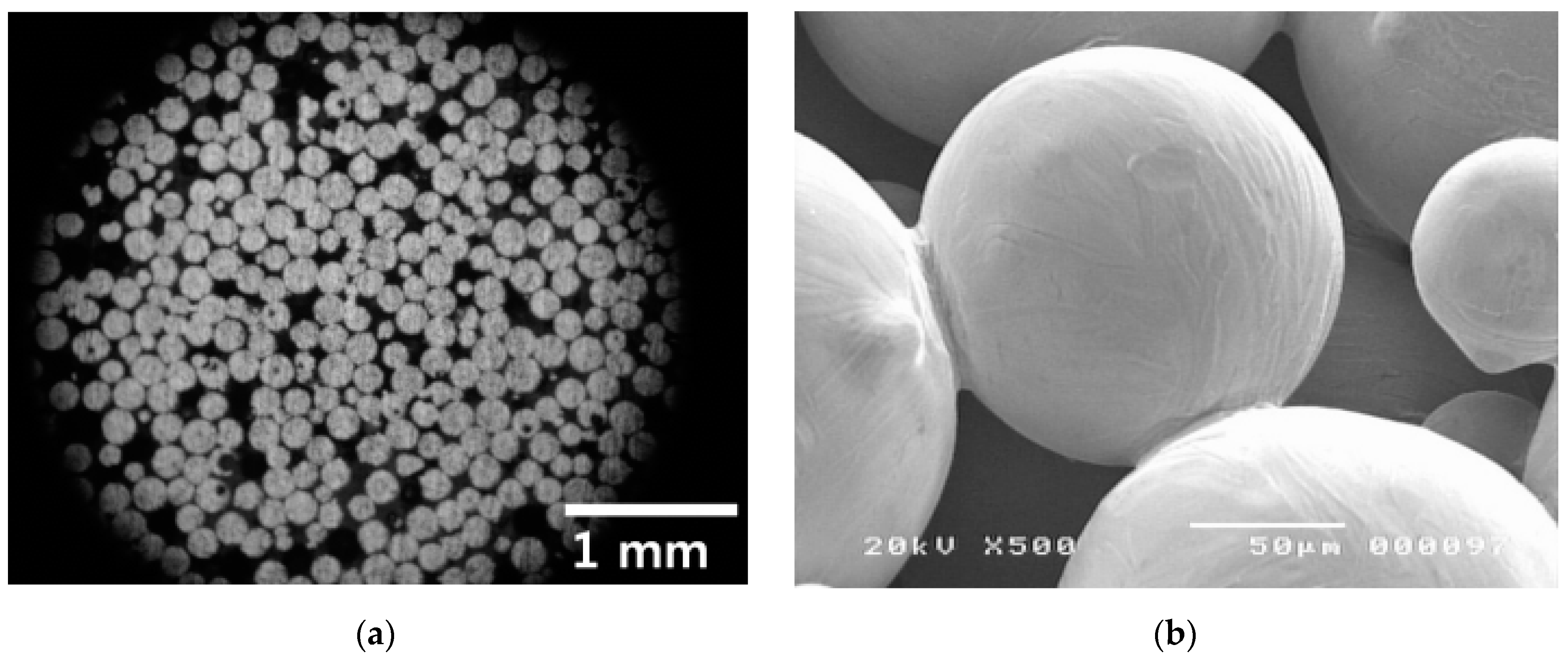
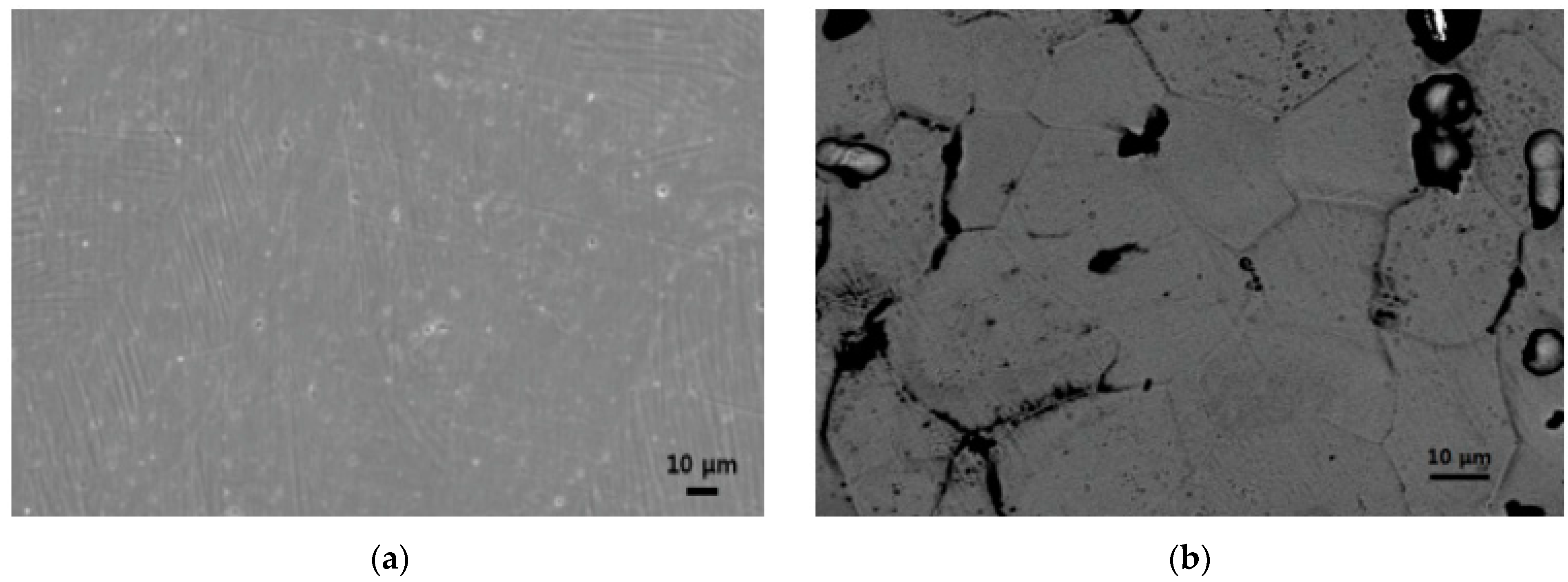
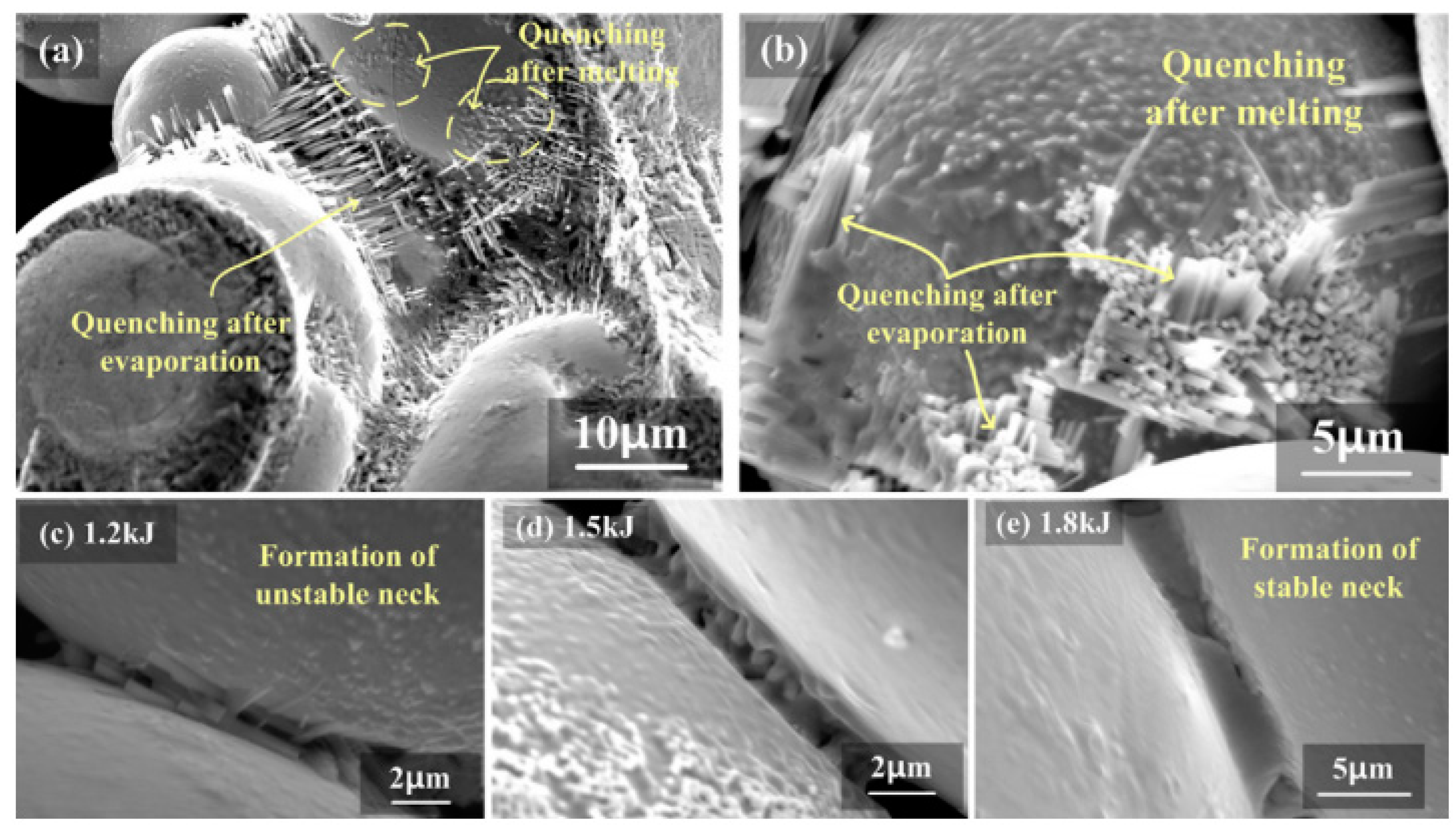
When the pinch pressure is above the yield strength of the processed materials at high temperature, densification takes place from the column centre towards the periphery. However, if the process parameters do not generate enough pressure, in absence of externally applied pressure, the result will be weakly bonded particles that could be easily removed from the compact (nevertheless, as later shown, temperature increase due to the Joule effect can also by itself help compaction). Figure 1 shows two different processing conditions of Ti powders without significant external applied pressure. In Figure 1a, the current passage is responsible for the formation of necks at the contact point of powders. In the centre of Figure 1b the necks eventually grow to sinter the powder aggregate showing a dense core because of the effect of the pinch pressure [41]. A review of several porous materials, including Ti, Nb and Ta, prepared by EDC can be found in [42].
The effect of the applied pressure can be checked by comparing the energy necessary to consolidate Ti powders [43]. When no external pressure is applied, proper consolidation needs 5 kJ/g [26], while only 3.6 kJ/g were needed when external pressure was applied [44].
Another important factor to take into account is the temperature reached in the powder particle contacts. Estimation of the temperature reached in powders by EDC can be calculated according to the equations in [35]. Computation is based on the specific heat of the powder, and the input power calculated by integrating current and voltage during the discharge. Temperature in the contacts of Ni powder particles, 100 μm in diameter and with 0.3 μm of oxide thickness, when processed with 0.125 kJ/g is estimated as 12,400 °C [35]. In Ti powder particle contacts, under processing conditions of 450 μF and 1.07 to 2.86 kJ/g, temperature reached between 1233 and 4925 °C [37]. Under the same processing conditions, Ti-6Al-4V powders reached between 1058 and 4752 °C [45]. The temperature in Ti-6Al-4V powder particle contacts was reduced to the range of 420 to 2378 °C under processing condition of 240 μF and 0.5 to 2.5 kJ/g [39]. Even higher temperatures of up to 2592.8 to 6192.8 °C are reported in mixed Ti-Al25 powder processed with 450 μF and 1.67 to 5 kJ/g [46], or up to 2004 to 5038 °C in mixed Ti-Si37.5 powder processed with 300 μF and 7.35 to 15.29 kJ/g [47]. As shown in Figure 2 for Ti powders [48], these temperatures are enough to ensure the formation of necks between the different particles, even when low applied pressures just ensure particles are in contact.
Nevertheless, it is worth noting that these estimated values seem in some cases much higher than actual temperatures that must be reached in particle contacts without making these contacts disintegrate.
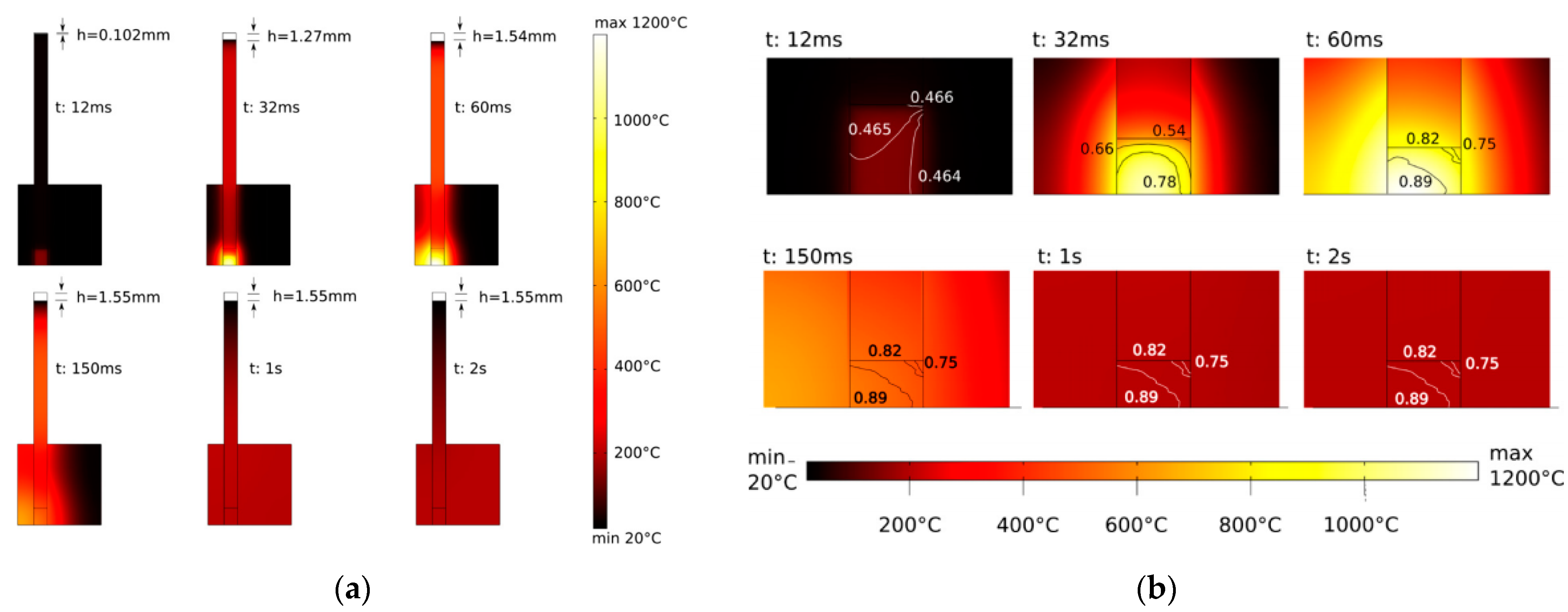
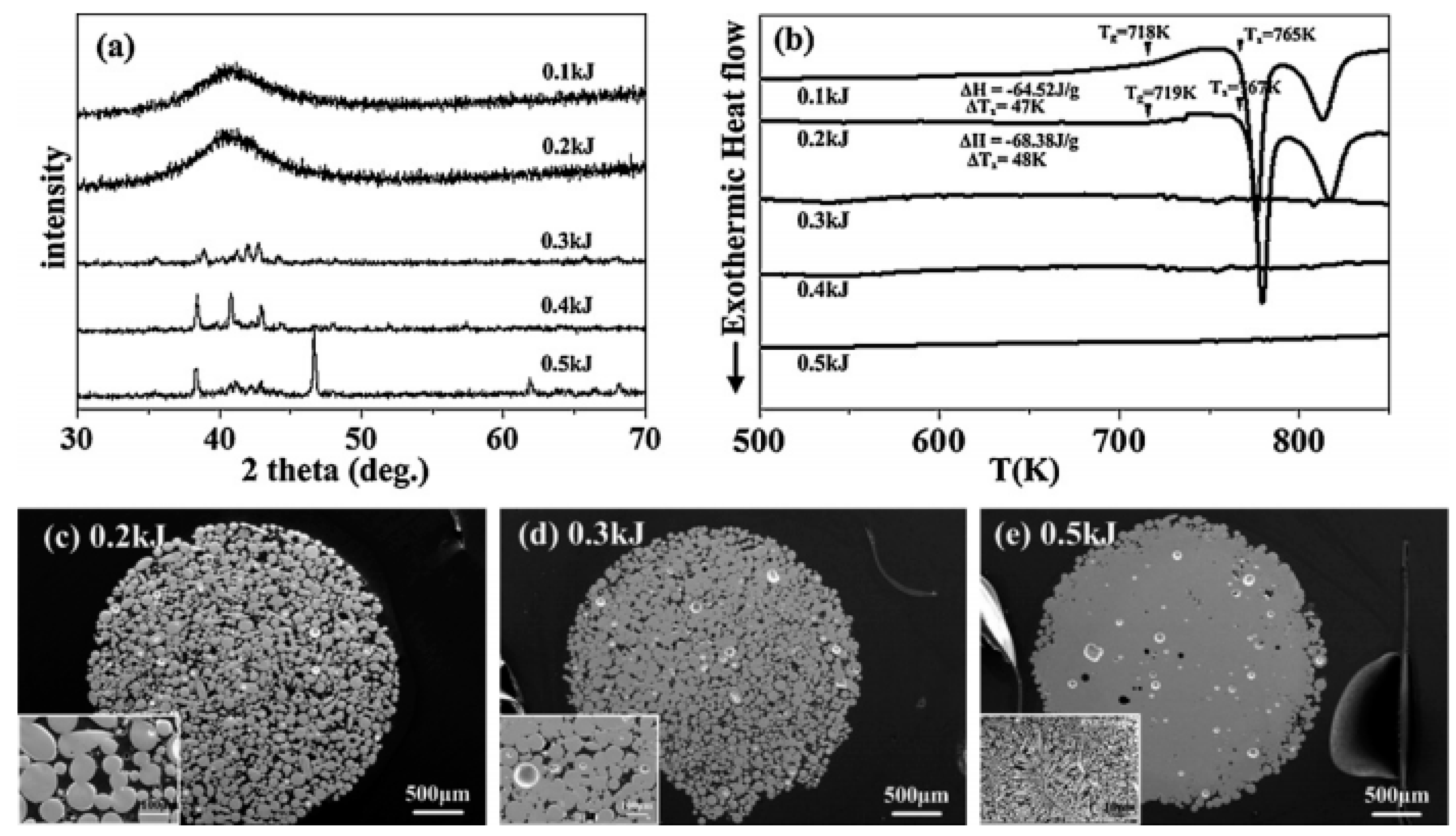
More complex models, allowing the prediction of several parameters in the process, have been developed. In particular, regarding temperature, more elaborated models can be found in [28,49,50]. The simulation of the EDC coupled process, including the electric, thermal, mechanical, and microstructural problems, has been carried out using the finite elements method (FEM) implemented in Comsol Multiphysics. The strategy followed in these works considers the powder column as a continuum media with a certain porosity, which properties are computed by the mixture rule of individual elemental powders constituting the material. Thus, the different parameters are continuously updated in function of the new values of temperature and density, obtaining the system evolution. The process has for instance been simulated for Cu powders [51] and for a mixture of mechanically alloyed (MA) Cu and diamond powders [52]. As shown in Figure 3, results for the latter system processed with an input energy of 4.12 kJ under 125 MPa, show a maximum temperature of 1350 °C achieved in the compact core, with a heating rate of 5 × 10⁴ K/s and cooling rate of 1.5 × 10⁴ K/s. Densification depends on the processing parameters, reaching a maximum relative density of 93.3%.
In addition, experimental measurements with a two-colour pyrometer have been carried out during EDC experiments of Ti powders [53]. Measured temperatures reached 5600–5800 °C, with a heating rate of 1 × 10⁶–1 × 10⁵ K/s, and cooling rate of 1 × 10⁶–1 × 10⁵ K/s.
Variations of the EDC technique have been developed. Capacitor discharge sintering (CDS) [54] consists of the combination of a single short impulse of intense electric current synchronized with a mechanical pulse, with energy being transferred after a predetermined level of pressure is reached. The main difference with EDC is that the electrical pulse is generated by a high voltage capacitor bank and then transformed to a high current–low voltage electro-magnetic discharge. Moreover, controlled atmosphere devices have been developed [55], being the process usually called environmental electric discharge sintering.
Moreover, high voltage electric discharges have also been applied to other purposes. Electric discharge-assisted mechanical milling [56] applies currents in the range of the kV to synthetize complex oxides powders in a short time. Microstructural transformations induced by high density electric current pulses have been studied in [57], including the formation of ultrafine grained microstructure and nanostructure during phase transformation as well as during recrystallization, formation of oriented microstructure, and segregation of inclusions. Finally, residual stresses can also be removed by electric current [58]. Nevertheless, most of these applications require the use of repeated discharges to be efficient processes. Similarly, repeated high voltage discharges can also be applied with the initial idea of consolidating materials. Thus, pulse plasma sintering [59] is a variant of EDC with repeated current pulses in vacuum, and with the possibility of previously heating the sample to a selected temperature.

2.2. Stages of the EDC Process

Typically, three or four stages have been identified according to the electrical resistance evolution of the powders during EDC processing. Based on Davies and Al-Hassani’s [60] electrical records on EDC of Ni powders, Kim et al. [35] redefined four different stages from Davies and Al-Hassani explanation of the process. Kim et al. calculated the pinch pressure at particle contacts, showing that the obtained value of 7.7 MPa for 38 µm Ni particles was not enough to disrupt the oxide layers at early stages of discharging. Thus, the first stage defined in [60], where the electronic breakdown of the oxide was enough to facilitate the formation of conducting fibres, was considered not acceptable. Nevertheless, after the electronic breakdown of the oxide in a few microseconds (stage I, lasting about 18 µs), and considering an oxide thickness of 10 nm and the energy released in the initial stage of discharge, the temperature increase at particles contact was estimated. The amount of Ni under the oxide that could be sublimated by the temperature increase was estimated. This produces a volume change, creating explosive forces that act outwards against the oxide films, removing and possibly melting them. This physical breakdown of the oxide layer, lasting up to 24 µs for the studied conditions, constitutes stage II and results in a resistance reduction of the powder column. Then, necks formation aided by the pinch pressures, lasting up to 35 µs, and necks growth and heat dissipation, up to reach the final 60 µs of the whole process, respectively, constitute stages III and IV.
More recently, three main different stages have been defined. In the first stage, sometimes considered as two different ones, and with a duration of about 10–15 µs for the studied Ti powders (as the other stages very much depending on the studied material and discharging parameters), resistance quickly decreases because of the electronic and later physical breakdown of the oxide layer surrounding powder particles, as shown in Figure 4. Conducting layers are formed in the powder column. In the second stage, about 100–130 µs in length, necks between powder particles are formed, even growing under the effect of the pinch pressure. Current flows in longitudinal and radial directions, interconnecting powder particles. The resistance in this stage slowly decreases [37]. Under appropriate conditions, this second stage could be characterized by the formation of a liquid column [47]. In the third stage, about 10 µs in length, again with a rapid drop of resistance, densification is promoted by the pinch forces from the centre to the periphery of the powder column [37]. The formation of a solid from a liquid column would account for this resistance decrease in such case. Additionally, a final fourth stage takes place when elements from the atmosphere diffuse or are absorbed, leading to oxidation, nitridation or carburization processes, which increase the resistance of the sintered powder column [47,61]. The effect of an externally applied pressure should be considered, if it is the case, in each one of these stages.
The different stages duration and the total duration of the process depend on the particular conditions and processing parameters. For instance, discharge times of 86, 124 and 153 μs were estimated for Ti powders and capacitances of 150, 300 and 450 μF [37]. In addition, the cooling time of the consolidated material depends on processing parameters, as well as on the thermal conductivity of the materials and the size of the compacted sample, being in the order of 2.5 s [27,28].
Some other effects, such as recrystallization, have also been considered to explain the EDC process. Based on experimental observations, the mechanisms behind the EDC process have been explained to depend on several phenomena [52]. Thus, the initial rearrangement of the particles, the subsequent strain hardening by intense plastic deformation at particle contacts, and the particle contact interfaces of Joule softening resulting from the electric current under constant pressure, should be considered. Softening combines the mechanical collapse of softened particles due to the interface temperature increase, and concurrent recrystallization. Atomized and ball-milled Cu, blended with diamond particles, were processed in this study. In atomized powders, recrystallization starts at the particle contact interfaces, which is more homogeneous for ball-milled powders. In any case, recrystallization will promote particle bonding, with pressure acting on these softened regions to promote material flow.

2.3. Influence of Powder Particles Oxide Layers in EDC

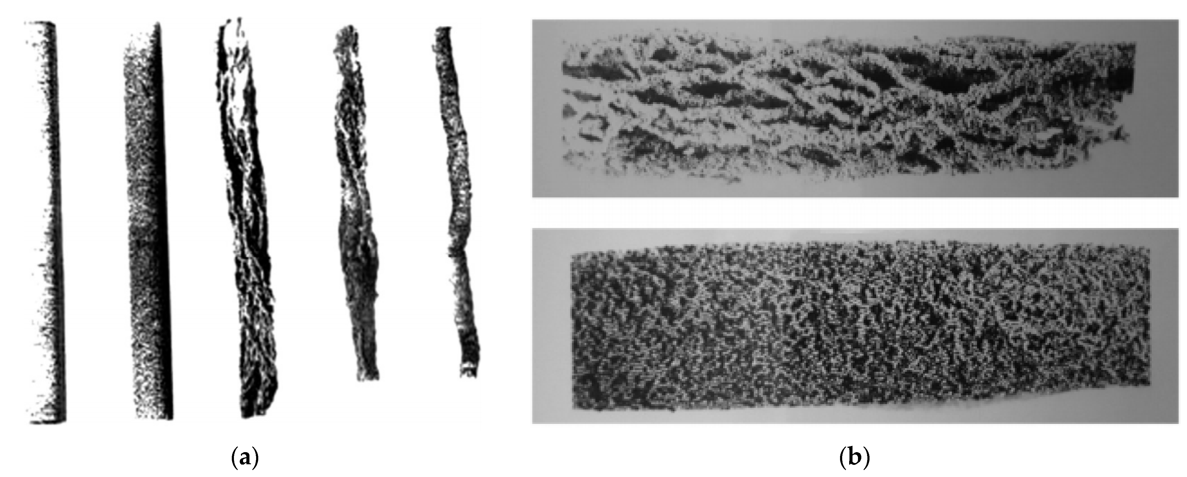
As previously discussed, the oxide layer surrounding particles is of primordial importance in EDC processes, being detrimental in both very thick and very thin layers. If the oxide does not surround the particles, insufficient local heat is generated, resulting weak inter-particle bonding and mechanical strength. In the case of thick layers, breakdown could not be completed, making the neck formation difficult and resulting in separate molten fibres or channels. Figure 5a shows the effect of oxide thickness increase in hydrogen annealed steel powders for different times, including conditions both below and beyond the limit thickness [62]. Once the oxide is thicker than the limit value, consolidation is not completed. Areas outside these channels contain particles not welded to each other, which reduces mechanical strength. Thus, once a critical oxide thickness is surpassed, compaction is not possible even increasing the discharge voltage, which only increases the thickness of the molten channels [62]. On the other hand, for constant voltage, higher capacitance also leads to thicker channels, but it does not result in a greater number of fibres [29], i.e., the breakdown of the oxide layers is not clearly affected by the voltage or capacitance.
For oxide thicknesses below the critical limit, increasing the discharge voltage beyond the breakdown produces more numerous fibres as shown in Figure 5b [29]. The breakdown voltage in slightly oxidized particles depends on the oxide thickness, for instance, artificially increasing the oxide thickness of particles with an average size of 110 µm from 0.5 to 3 µm in steel powder, increases the breakdown voltage from 2 to 5 kV [62]. EDC seems to be more influenced by discharge voltage than by capacitance. It could be said that for a particular energy level, high voltage and low capacitance could help to create a uniform distribution of current density, leading to the appearance of a higher number of channels and avoiding undesirable phenomena [29].
Repeated discharges on the same powder column have also been tested. As expected, densification does not increase. Once the channels for the current are formed, the resistance of the column decreases and the specimen behaves as a conductor, without any thermal effect [26]. However, according to [63] a gradual increase of voltage in different pulses produced bigger necks between particles and stronger materials. Moreover, consolidation experiments have been carried out with the discharge consisting of two half-periods, with the current amplitude in the second half being approximately one third of that in the first half [64].
Some more detailed estimations can be carried out on the effect of the process on the oxide layers. According to [35], and considering that the energy of 0.125 kJ/g discharged on 100 µm Ni powders was entirely consumed for heating the metal–oxide interface, a total amount of 0.059 g of Ni can be sublimated (sublimation energy of 8.45 kJ/g at the sublimation temperature of 3110 K). Thus, considering a linear packing, 0.69 × 10⁻⁷ g per particle is transformed to gas with a volume expansion of 0.3 × 10⁻⁹ m3. In practice, one-twelfth of these values should be considered for particles closely packed. This volume change can exert an outward pressure of about 4 GPa at the oxide–particle interface, enough to explosively disrupt the oxide film away from the nickel particle. Therefore, even without external applied pressure, the electrical sintering process can be carried out.

2.4. Historical Development of the EDC Process

Focusing on the historical development of the EDC technique, it can be said that the first experiments were carried out by researchers of Manchester and Cambridge (UK) in 1976 [36]. The work started by Al-Hassani and Johnson continued until 1993 [65], although disciples such as Can continued the research in Bursa (Turkey) from 1993 [65] to 2004 [66]; also, Darvizeh started working on this discipline in 1988 [67], continuing this research branch in Rasth (Iran) until now [29].
The initial published results stimulated other researchers to study the technique. Japanese researchers from Kyoto studied the process in 1993–1994 [68], and from Ichikawa and Kure in 1996–1998 [69,70]. Even earlier, in 1988, work was carried out in Kentucky (US) by Okazaki [35], which extended until 2000 [71], although colleagues such as Reucroft continued the work from 2006 [41] to 2015 [37]. The collaboration of Okazaki in 1991 with Lee [72], from South Korea, opened a new branch in this country, with publications in EDC from 1999 [39] until now [73]. Korean researchers from Seoul, Busan, Gyeongju, Daejeon, Sejong, Gwangju, Kyungju, Incheon, Cheonan, Iksan or Goyang have actively participated in these works.
The technique also started to be studied in other places around the world. Works carried out in Mumbai (India) can be found in 2000, mainly with low voltage discharges [26], or in the period 2007–2008 in Kharagpur (India) [74,75]. In Shenyang, China, works were carried out from 2000 [76] to 2015 [57]. In addition, researchers from Beijing and Chegdu have recently started to use this technique [58,77]. In Changhua and Hsinchu (Taiwan) studies were carried out with low voltage discharges some years ago [78].
One of the most prolific geographical areas studying electrical sintering techniques is the former Union of Soviet Socialist Republics (USSR). They also inquired into the possibilities of EDC. Work carried out in Mykolaiv, Nikolaev and Kiev (Ukraine) deals both with material production [79] and mainly with discharges in particle–fluid suspensions and the effect on powder particles, as reported from 2011 to 2017 [80,81]. Nevertheless, regarding consolidation of powders, the most extensive research has been carried out in Russia. The work regarding sintering through electricity was studied in Moscow from 1976 [82], continuing 15 years ago with the use of high voltage capacitors [83], and is still ongoing [84]. Work from Minsk, Belarus was produced from 2004 [49] to 2017 [85].
In Europe, researchers from Turin and Florence (Italy) have been working on EDC from 2008 [44,86], more specifically in CDS, the variant to allow the use of low voltage in powders. Moreover, work has also been carried out in Clare (Ireland) [87] and from 2004 in Bochum (Germany) [88,89].

3. Equipment and Materials

3.1. Equipment

We will first focus on the equipment used to carry out the process. The main and common characteristic of this technique is the use of a capacitor bank to store the energy used to sinter the powders. The subjacent idea is to rise the power of the process to limits that cannot be achieved by using electricity directly from the electric network. On the other hand, in order to increase the stored energy E, the capacitance C or the charging voltage V can be changed, which is the effect of the voltage higher than that of the capacitance (E = ½·C·V2).
Many researchers have opted to use custom-made equipment in the electric part of the process. The electric circuit and control electronics are usually adapted to commercial hydraulic or pneumatic presses. Indeed, the only requirement between both parts is to ensure the appropriate insulation that guarantees the current to pass through the powder inside the die, avoiding current leaks and the danger that this can suppose.
The most extended configurations are shown in Figure 6.
As shown in Figure 6a, the initial idea was the direct discharge on the powders of a capacitor bank charged at the desired voltage through a current transformer. The electric circuit can be represented by a series resistor-inductor-capacitor (RLC) circuit, the characteristic second order differential equation of which is given in Equation (2). This equation can be obtained by differentiating, with respect to time t, the voltage balance of the RLC circuit at the time that considering inductance L and capacitance C with constant values [36,62].
L d 2 I d t 2   +   R d I d t   +   ( d R d t   +   1 C ) I   =   0
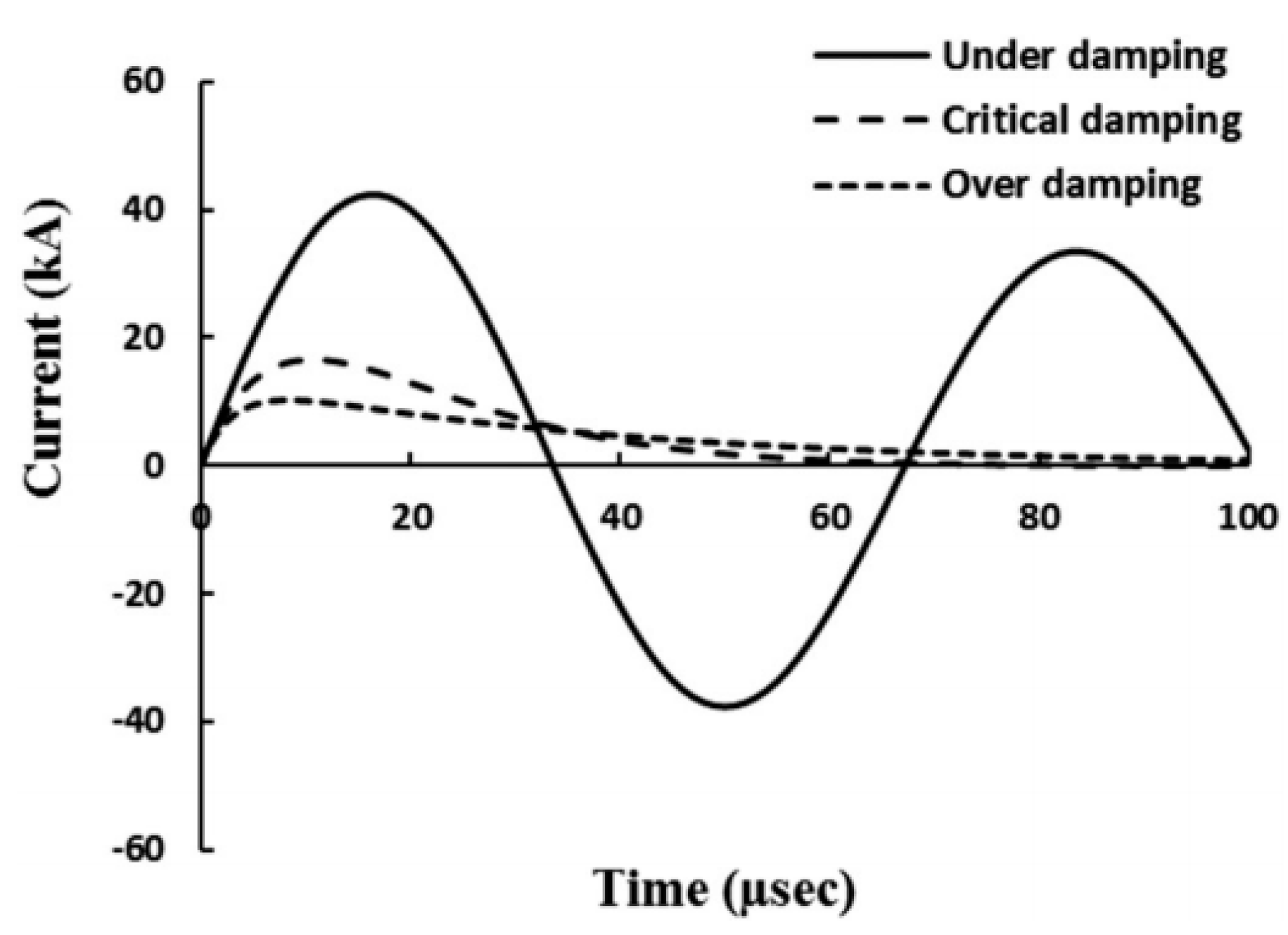
The solution for Equation (2) with variable resistance R is not immediate. For constant R, the current intensity function in the moment that the circuit is closed leads to different forms depending on the values of R, L and C. These solutions correspond to the over- damped, critically-damped and under-damped cases, the typical forms of which are shown in Figure 7. Results are in good agreement with records of the current pulses that are actually carried out with a Rogowski coil.
Other configurations appeared next, with the use of two power circuits [91] and allowing for high power but low voltages on the powder compact (see Figure 6b). The circuit obtains low voltage and high current (in the secondary circuit) from high voltage and low current (stored in capacitors in the primary circuit). The electric pulse and application of pressure are synchronized to act together in the desired moment. This technique is nowadays referred to as capacitor discharge sintering (CDS) [54], or electro sinter forging (ESF) [92]. A review on the actual situation of this technique can be found in [93]. This configuration limits the discharges and local plasma formation during the process, and can use switches based on power solid-state devices instead of ignitrons, increasing the reliability of the equipment [43]. Thus, in [43] the equipment used was adapted from commercial capacitor discharge welding apparatus, with voltages on the primary circuit of about 1.5–3.5 kV, and voltages on the compacts ranging from 5 to 30 V. Nevertheless, it should be noted that the development of the power electronics in recent years allows the use of a direct discharge scheme with the use of solid-state devices.
Other configurations were also developed, such as the setup with pressure applied perpendicular to the current flow [64].
As previously commented, most researchers have opted for custom equipment, however, commercial equipment consisting of industrial capacitor discharge welding units can be used, such as those provided by Manfred Schlemmer GmbH in Germany [94], or by Maggi Welding SPA [95]. Moreover, specific equipment for CDS (the configuration with high and low voltage circuits) was used by researchers from the Italian company EPoS [96]. High voltage equipment (“Impulse-BM”) is also provided by “Potok” LCC, Rostov-on-Don, Russia, with voltages and applied pressures of up to 6 kV and 300 MPa [97].

3.2. Studied Materials

Pure iron is a very well-known material in traditional sintering and therefore a candidate to make any initial study on new sintering techniques. Thus, development studies on EDC in the UK were carried out with iron [36,98], being iron also studied in Japan after being mechanically ground [68], Italy [43], Russia [27,28,99] and Iran [29]. The effect of electric discharges on Fe particle suspensions were studies in Ukraine [100].
Plain carbon steel was processed by EDC in the UK [67,101]. Several other studies with iron alloys can be cited, for instance, porous stainless steel filters have been consolidated in Turkey [66], wear resistance cold worked steel in Germany [94], AISI M2 high speed steels [43] and Fe–Cr–Mo steel [102] in Italy, heat resistant steel [27] and 13Cr-2Mo oxide dispersion strengthened (ODS) steel [103] in Russia, pipeline steel in China [58], and M84 steel in Iran [29,62].
Mixtures as Fe-base-TiC (Ferro-Titanit Nikro128) powders were studied in Germany [104], Fe-diamond in Ireland [87], and Fe-20TiC mixed with diamond powder [80], or Fe-20Ti-5B4C powders [100] in Ukraine.
A different idea was considered of interest from the early studies in Japan [70], where Fe-9Si-13B amorphous soft magnetic alloys were consolidated. The idea of preserving the amorphous state with this quick process was underlain in these experiments. The little influence of the process on the microstructure was also studied on MA Fe-1.5Mo powders [105] or MA AISI M2 [54] in Italy, and even the possibility of refining the microstructure of low-carbon steels from coarse grains was studied in China [106].
Additionally, from the development of the EDC technique, Al alloys were studied. Research carried out in the US included the consolidation of Al-11Fe-1V alloy [107], as well as high strength Al alloys of composition Al-5Ni-2Cu-1.4Ti-0.4Zr-0.2Mm, both commercial and obtained after mechanical alloying elemental powder [108]. The goal in these alloys was to obtain amorphous structures or thermally stable fine intermetallics with low diffusivity in Al [71]. More recent applications of EDC to Al powders include, for instance, the research in China with Al-12Si powders [77].
Regarding Ti-base materials, EDC processing of pure Ti was studied in India [26], Italy [44], and specifically for medical implants, in Korea [37,41,48,55,109] and Belarus [42]. This later research group has also studied the Ti-6Al-4V alloy, initially in the US [39,72,107] and more extensively in Korea [38,45,61,110,111,112,113,114]. In addition, MA Ti-Si37.5 powders [115,116], mixed Ti-Si37.5 powders [40], Ti-Al25 [46,47], Ti-28Zr-20Ni [117], or mixtures Ti-TiC [73] have also been studied in Korea.
Pure Ni powder has been processed in the UK [60] and US [35]. Ni has also been used in general purposes studies in Italy [43] and Iran [29]. Ni-Ti alloys have been studied in Italy [118,119].
Concerning Cu, pure Cu was studied in Iran [62] and Italy [43,120,121]. The theoretical behaviour of Cu powders is simulated in Italy [51]. Studies in China focused on Cu-Zn alloys and the formation of nanophases after EDC [76]. Recently, the eutectic Cu-14.5Ag-1.5Ni alloy has been used in studied about the effects of the circuit parameters in Iran [29], and the alloy Cu-15Sn in Italy [86]. Copper-diamond beads have been theoretically simulated during CDS and experimentally studied in Italy [52], and Cu-TiB2 in Russia [64]. In Korea, amorphous Cu-22Zr-18Ti-6Ni powders have also been consolidated by EDC [122,123].
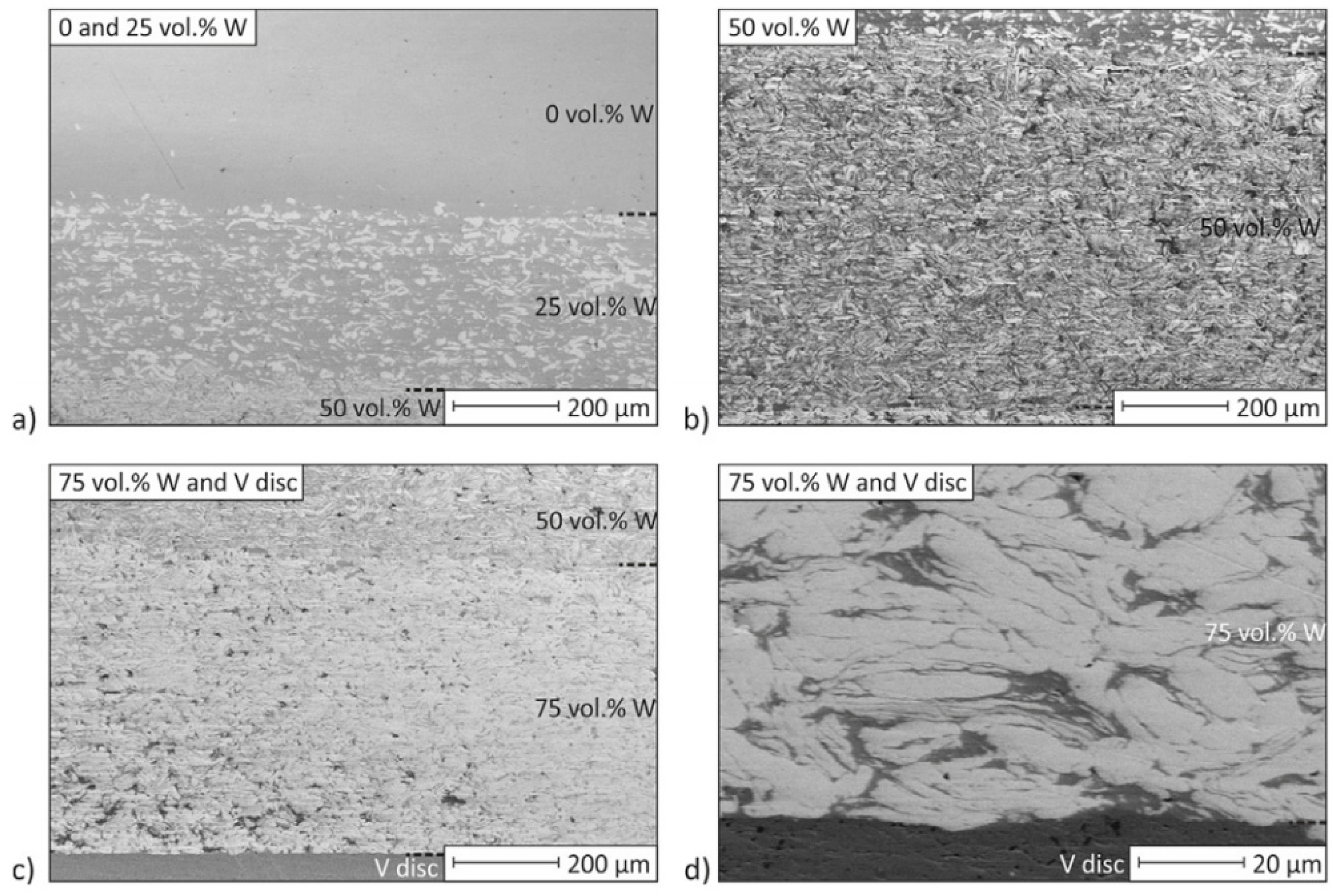
The study of hard metal processing has been carried out on WC-Co powders in China [50,124,125], and Russia [90]. Moreover, WC-TiC-Co powders were studied in Italy [126]. Pure W powders have been processed by EDC in Korea [123], alloys as W-6.93Ni-3.12Fe in Russia [84], and functionally graded Fe-W composites have been fabricated in Germany [88]. WCCo–diamond suspensions were treated by electrical discharges in Ukraine [80].
Finally, several other compositions have been processed by EDC. Some of these materials include the study of Sn and Zn elemental powders in India [26], and Au powders [92] and Mo powders as part of a general study [43] processed by CDS, in Italy. Other studies include processing Co-base amorphous alloys in Japan [69], Ag-Ni paste in Taiwan [78], Zr-1Nb alloy [127] and uranium nitride [97] in Russia, or Nd-Fe-B powders for permanent magnets in Germany [128]. Nanocrystalline MA Nb-23Al powders were studied in the US [71,129]. Diamond powder [130] and B4C powder suspensions [81] have been treated by electric pulses in Ukraine.

3.3. Materials Consolidation Conditions

Maybe the most important parameters to control EDC experiments are those of an electrical nature, although the mechanically applied pressure can also very much affect the processing results. The nature of the die, punches, powder characteristics and other factors in the process should not be forgotten.
Focusing on the electrical parameters, it is of paramount importance to achieve the necessary energy level for actually consolidating the powders. The energy stored in the capacitors and transferred linearly to the powders depends on the capacitance and in square form on the charging voltage. As aforementioned, not only the total energy affects the results, but also different results can be obtained for the same total energy depending on the capacitance and charging voltage. Table 1 gathers the usual ranges of energy, capacitances and voltages that several research centres have applied to consolidate powders.
According to the values gathered in Table 1, the stored energy used in experiments is quite different for different materials and conditions, ranging from about 0.5 to more than 50 kJ and a mean value in the order of 6 kJ. Values range per unit mass is narrower, from about 0.5 to 20 kJ/g, with a mean value of about 3 kJ/g. This energy is reached by using capacitances of a few hundreds μF although reaching up to 7500 μF, and charging voltages of a few kV, reaching values of up to 13.5 kV. The external applied pressure ranges from that to ensure a good contact between electrode and powders to values of hundreds of MPa. Finally, the process is usually studied with cylindrical dies from 3 to 19 mm in diameter. There are not however clear values ranges for particular compositions, which means that the optimal experimental conditions have to be attained by testing the studied material.
It should be finally noted the differences among authors when reporting the values of the process parameters. In order to reach a better understanding of the process, and make possible to narrow down the aforementioned mean values, it would be desirable to find or calculate specific energies instead of total energies. Moreover, an important parameter that is not always accessible is the current density passing through the powder column to reach the reported results.

4. Analysis of Literature Results

4.1. Iron-Base

The initial tests of the EDC technique in the UK were carried out with Fe powders, with the idea of producing iron metallic bars that should be further processed in swaging dies to increase density [36]. No external pressure but that necessary to have a good contact in the electric circuit was applied; nevertheless, the pinch effect caused by the discharge produced a density increase of up to 20%, reaching a relative density of 59% in a time of approximately 50 µs. It was checked that extreme conditions, i.e., current densities higher than 125 kA/cm2, caused the explosion of the powder column. This value has, however, been later clearly surpassed with Fe powders by other researchers, reaching for instance 234 kA/cm2 [28]. Depending on the applied pressure and energy set in the capacitor bank, the process can make part of the powder to reach critical viscosity values, being thrown out from the die apparently in liquid state and even causing the destruction of the die [43]. It has been shown [27] that there is a power law dependence between the applied pressure and the electrical conductivity of the Fe powder column, which undoubtedly affects this behaviour.
Initial studies [36] also included the effect of the electrical resistance of the powders, not taking into account the influence of the applied pressure but directly caused by the oxides covering the powder particles (indeed, experiments were carried out with different powder particle sizes to check the effect of the oxides, present in higher amount in small particles). It was found that the current flowing through smaller powders was lower. It was also checked that increasing the length of the column increases resistance, and therefore the current passing through the powders decreases, and the attained density decreases. Increasing the section of the powder column did not necessarily affect the density, because despite the fact that resistance decreased, the current density was smaller.
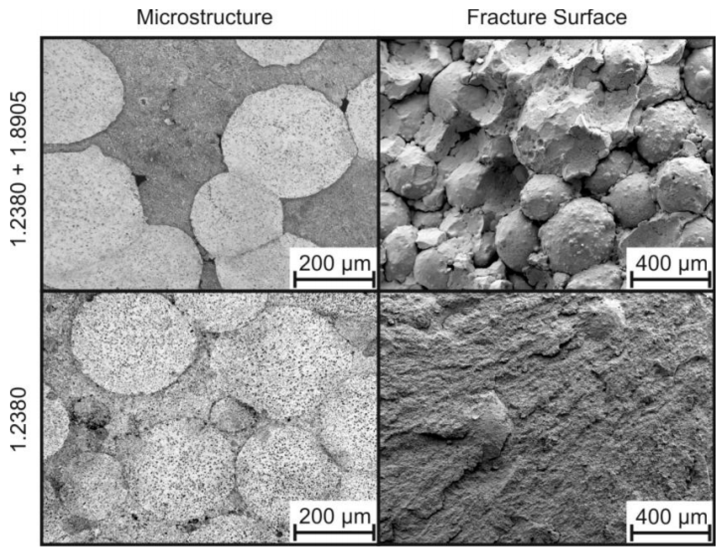
Regarding density distribution, a certain increase near the electrodes was measured, attributed to a higher temperature combined with the effect of the magnetic field [36]. Years later, higher porosity near the surface was reported by the same authors [131], attributing its aid in filling the interparticle pores to the higher pinch effect in the centre of the sample. A similar behaviour has been reported, with higher porosity in the whole specimen periphery, based on microhardness measurements in steel parts [54]. Similarly, for experiments conducted with high intensity and low voltage in steel powders [94], densification from the centre to the periphery of the compact is reported. In this later study, it has been found that when sintering powders of different composition, a dense microstructure higher than 99% is attained, but fracture surfaces showed weak adhesion in between the powder particles of dissimilar powders (Figure 8). The different strengths are responsible for finding a ductile fracture behaviour of 1.8905 steel and no failure of 1.2380 steel powder grains. It is also observed that powder particles of different composition have not been sintered.
Nevertheless, this technique can produce, under proper conditions, relatively homogeneous samples. In the uniformly consolidated area and for high consolidation energies, residual pores tend to be spherical, with uniform size and located at three point junctions [54]. Pressure is a key parameter to control the electrical resistance of the specimen, the densification process and the pore size and distribution, whereas discharge energy controls the oxide elimination at interparticle contacts and the grain growth [54]. For high intensity and low voltage discharges [94], it is also found that necks between particles become larger and density increases with discharge energy, being pores filled up with molten material from the particle boundaries, and that it is possible to reach fully dense parts.
The influence of ESF processing conditions on Fe–1.5% Cr–0.2% Mo alloy was studied in [102]. In particular, voltage and pressure were varied to study the energy released, the attained density, and mechanical properties as transverse rupture strength and Vickers hardness. Energies around 1.25 and 2.1 kJ/g, and pressures in the order of 245 and 185 MPa were used in cylindrical and rectangular specimens, respectively. A detailed statistical analysis was carried out to optimize the processing parameters. Higher density and mechanical properties were obtained by increasing the energy loaded in the capacitor banks, by lowering the inter-plunger distance at the end of the discharge, and by lowering the pressure before discharge. The resistance attained with the optimized parameters reach 1800 MPa, with fracture surfaces consisting of dimples homogeneously distributed throughout the entire surface, and no trace of the initial particles recognizable in the fracture surface.
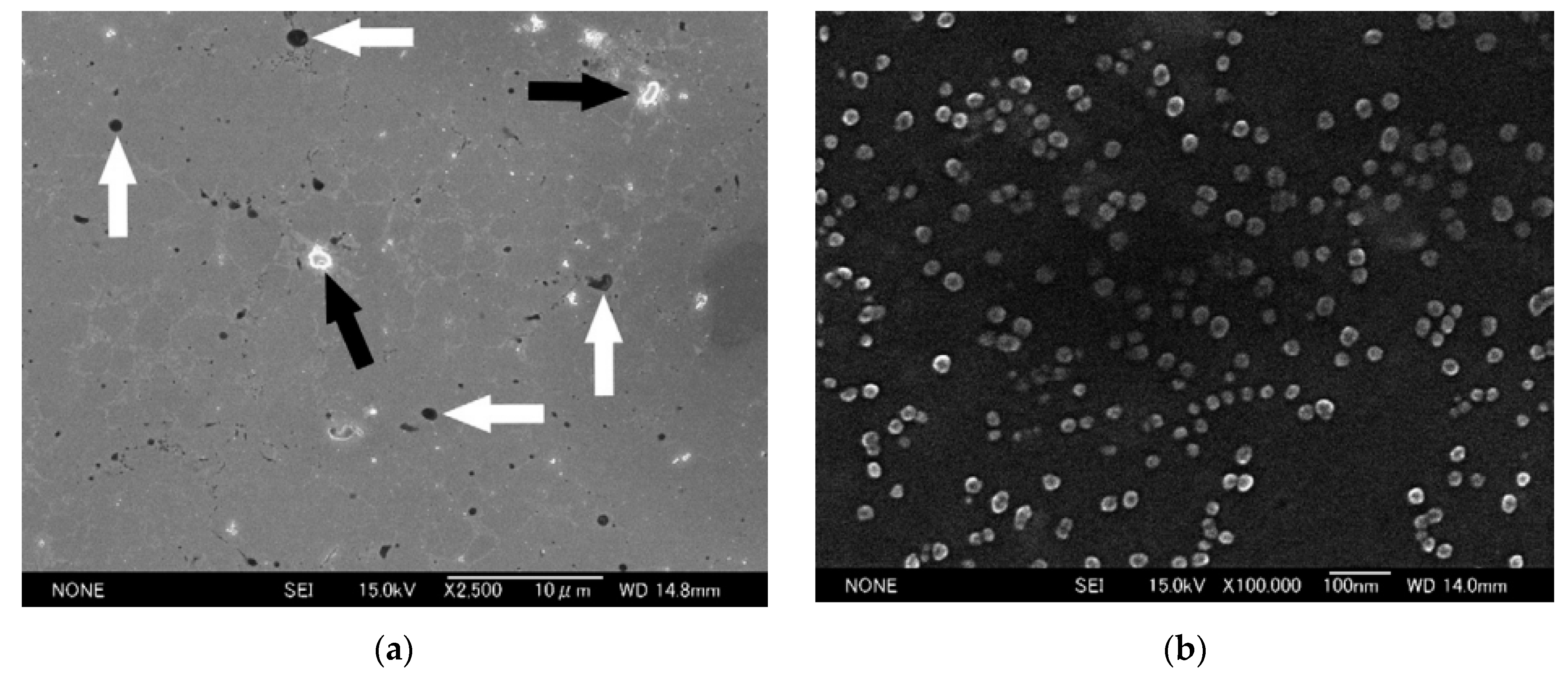
Since one of the main attractions of this technique is the very short heating period, early studies already focused on preserving the grain size of the material after the EDC process. Thus, mechanically ground Fe powders were tested [68], preserving a size of 50 nm after EDC consolidation. Recent studies have also deepened in this idea. MA AISI M2 powders were consolidated after pressed at 200–300 MPa with energies from 0.9 to 1.5 kJ/g [54]. Under optimal processing conditions, 300 MPa and 1.2 kJ/g, the final grain size was 10 nm, with hardness of 712 HV and density of 7.72 g/cm3 (95% relative density), reaching 1.5 kJ/g increased grain size to more than 100 nm, also increasing density up to 8.1 g/cm3 (99.75% relative density), but decreasing hardness to 516 HV. The attained microstructure consisted of ferrite and carbides. Large and complex carbides were present both in the starting powder and consolidated samples, and very fine carbides of about 10–15 nm, smaller than those usually found in conventionally processed M2 steels, were also found with a homogeneous distribution in the matrix (see Figure 9). The same authors have also processed ultra-fine ball-milled (96 h in a planetary ball mill and initial grain size of 17 ± 2 nm) powders of Fe–1.5% Mo alloy with 250 MPa and 3.1 kJ/g (energies below 1.25 kJ/g did not sinter these powders). These conditions allowed reaching a 97.5% density and a final grain size of around 330 nm. [43].
An extreme situation in the idea of preserving a particular microstructure after consolidation consists of working with amorphous materials. Thus, amorphous Fe-9Si-13B ribbons were joined by EDC [70], reaching relative densities between 93 and 98%. Depending on the discharge energy, the amorphous structure can be maintained. For 0.6 kJ/g, the partially melted interface among ribbons still maintains the amorphous structure after requenching, as studied by TEM, and a vein pattern of amorphous structures is observed at the tensile fracture surface. However, for energies above 1.5 kJ/g the structure of the melted region starts changing to crystalline, with the appearance of metastable phases. A brittle shell-pattern tensile fracture surface is clearly observed for 2.0 kJ/g. As expected, magnetic properties deteriorate for input energies above 1.5 kJ/g.
The processing of other Fe-base materials by EDC include working with oxide dispersion strengthened (ODS) steels with micro or nanoparticles, with high creep properties and possible use for nuclear applications [103]. In particular, material flakes of ferritic/martensitic 13Cr-2Mo special reactor steel were milled to obtain a powder of about 400 µm, and then mixed and MA with nanoscale Y2O3 powder of about 50 nm. EDC allows obtaining a homogeneous microstructure in high density compacts with low grain growth and without thermal phase transformations, therefore with adequate mechanical properties. Samples with 90 to 97.5% relative density were obtained, with better results when applying the appropriate pressure to get good inter-particle contacts without decreasing resistivity in excess, therefore allowing better sintering. 200 MPa and 4.2 kV were checked to be the best processing conditions, resulting a current of about 270 kA/cm2, a microhardness of about 650 HV and a relative density of 97.5% for a 0.3 wt.% of Y2O3. Microhardness resulted in some cases some higher at the specimen periphery, attributed to a higher degree of plastic deformation and higher heating and cooling rates that can provoke the appearance of a martensitic structure.
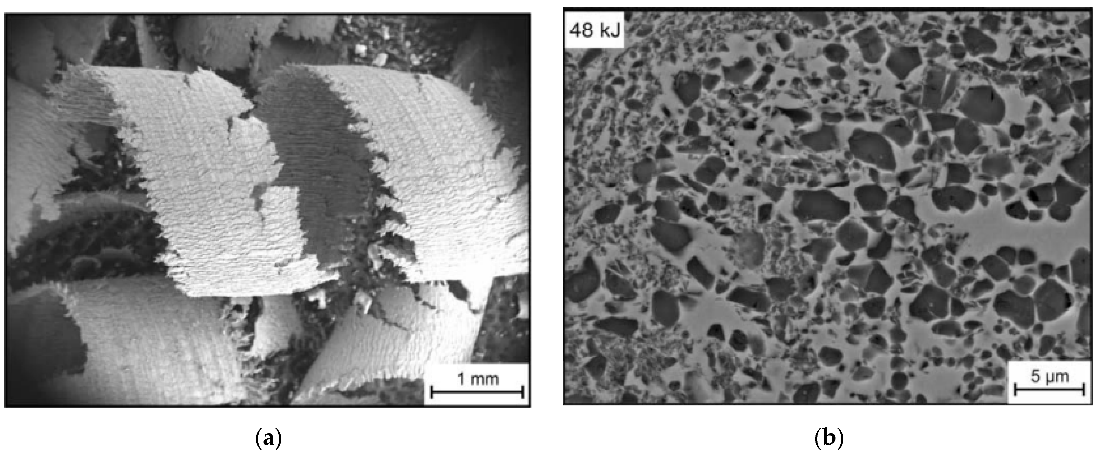
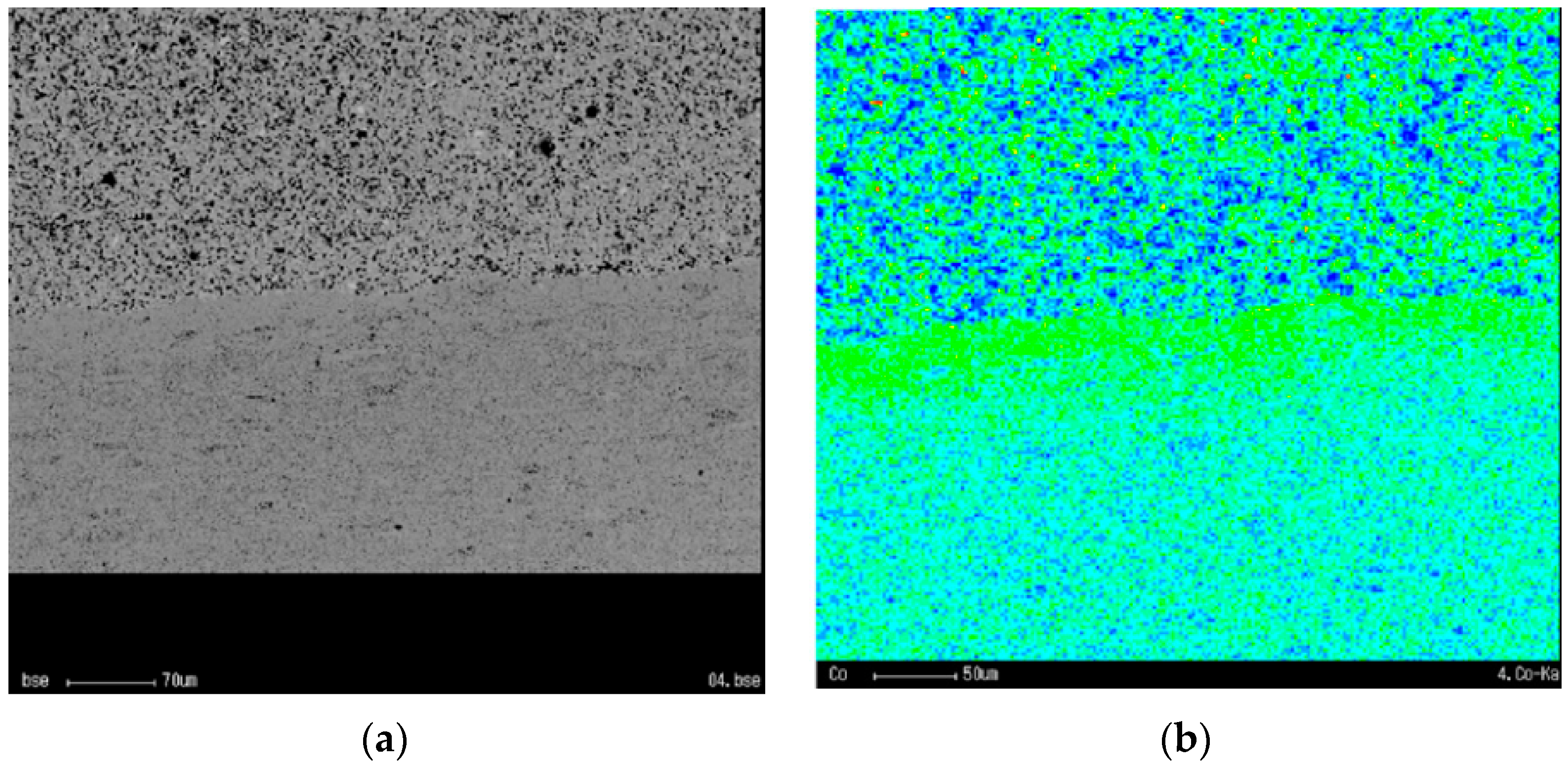
Another Fe-base material processed by EDC consists of the recycling of the expensive chips of machined annealed Ferro-Titanit®, consisting of a metallic matrix and approx. 50 vol.% of hard Ti-monocarbides. This material is used for wear and corrosion resistance applications. Chips can be converted to bulk form by EDC (see Figure 10). Resulting microstructure consists of TiC with a size of approximately 2 μm and hardness similar to the original material [104].
Fe-diamond tools for stone cutting applications have been processed by ESF [87]. Fe powders were alloyed with 0.8 wt.% C to improve properties and mixed with coated diamond at a concentration of 16. A 1.9 kJ/g energy pulse at 198 MPa, followed by a second pulse at 2.2 kJ/g, was used to sinter the powders. High densification can be achieved by repeating sintering pulses, allowing the use of lower force and energy. An average relative density of about 95% was measured. Tests were done on granite at a depth of cut of 1cm and a head speed of 400 cm/min. Results show that ESF blades can equal the results obtained with a high quality conventionally hot pressed saw blade in terms of cutting life.
However, not only maintaining a fine microstructure after EDC processing has been pursued, but also decreasing the grain size on bulk parts. Thus, electropulses can be used to prepare ultrafine grain samples from coarse grain materials. Using the ferrite to austenite solid-state phase transformation, low carbon steels were treated under controlled current density, heating, and cooling rates [106]. It was confirmed that the final grain size decreased for a higher current density and heating rate, obtaining a material free of porosity and contamination, and with no high microstrain, resulting in a greatly increased tensile strength and ductility which does not decrease with respect to the original coarse-grained material.
Another application of EDC, tested on austenized and water quenched X80 pipeline steel, consisted of reducing residual stressed through electrical discharges [58]. The martensite phase resulted in phase transition stresses, and the different cooling rate at different depths in thermal stresses, with a global result of tensile stress on the surface and compressive stress in the core. The idea of applying EDC is based on the electroplastic effect, which makes it possible to reduce the force parameters of the metal-forming process. Results showed that for a current density of 5562 kA/mm2, the residual stress was removed over 80%.
Finally, other applications of EDC consists of the treatment of powder suspensions, with the idea of reducing particles size. Both water and kerosene suspensions with Fe–20TiC powders [80] and Fe-20Ti-5B4C powder mixtures [101] were tested. The pressure in the discharge channel generates shock waves surpassing the tensile strength of the powder particles, therefore breaking them. Discharges of 200 kJ/dm3 for the kerosene Fe-20TiC powder suspension reduced the mean particles size to about 50 µm—one third of the original size—resulting a mixture of fine and coarse angular particles. Increasing energy to 600 kJ/dm3 resulted in a size decrease by almost one hundredth, to 1.5 µm. The effects of kerosene suspension were bigger on the microstructure of the powders, resulting acicular shapes because of a higher carbon content due to the decomposition of hydrocarbon molecules.
Fe powders were used to mathematically model the process [65,102]. Improvement of this model checked with Fe powders can be found in more recent studies, i.e., [28].

4.2. Aluminium-Base

The idea of preserving the microstructure present in powders has also been tested on Al-base materials. EDC was used with the objective of avoiding excessive precipitation of solute atoms and formation of undesirable amounts of too large compounds. Thus, rapidly solidified Al-11Fe-1V powders [107], and atomized [108] and both atomized and MA [71] Al-5Ni-2Cu-1.4Ti-0.4Zr-0.2Mm powders were subjected to EDC. Applied pressures of up to 450 MPa and input energies of up to 3.8 kJ/g were tested. An initial green density of about 80% allowed to reach densities of up to 99%. Even at the maximum input energy, it was checked that grain growth of neither Al nor of phases present in the as-received powders, mainly Al3Ni, occurred, with most of the alloying element remaining in a solid solution. It was also observed that powder particles appeared welded together without traces of oxide films. Moreover, the Joule heat made precipitates near particle boundaries turn to a solid solution, and the quick heat dissipation to the matrix avoided the appearance of new precipitates. In MA powders, an almost precipitation-free matrix was observed. This process resulted in true compressive mechanical properties exceeding strengths of 800 MPa and a ductility of 24%.
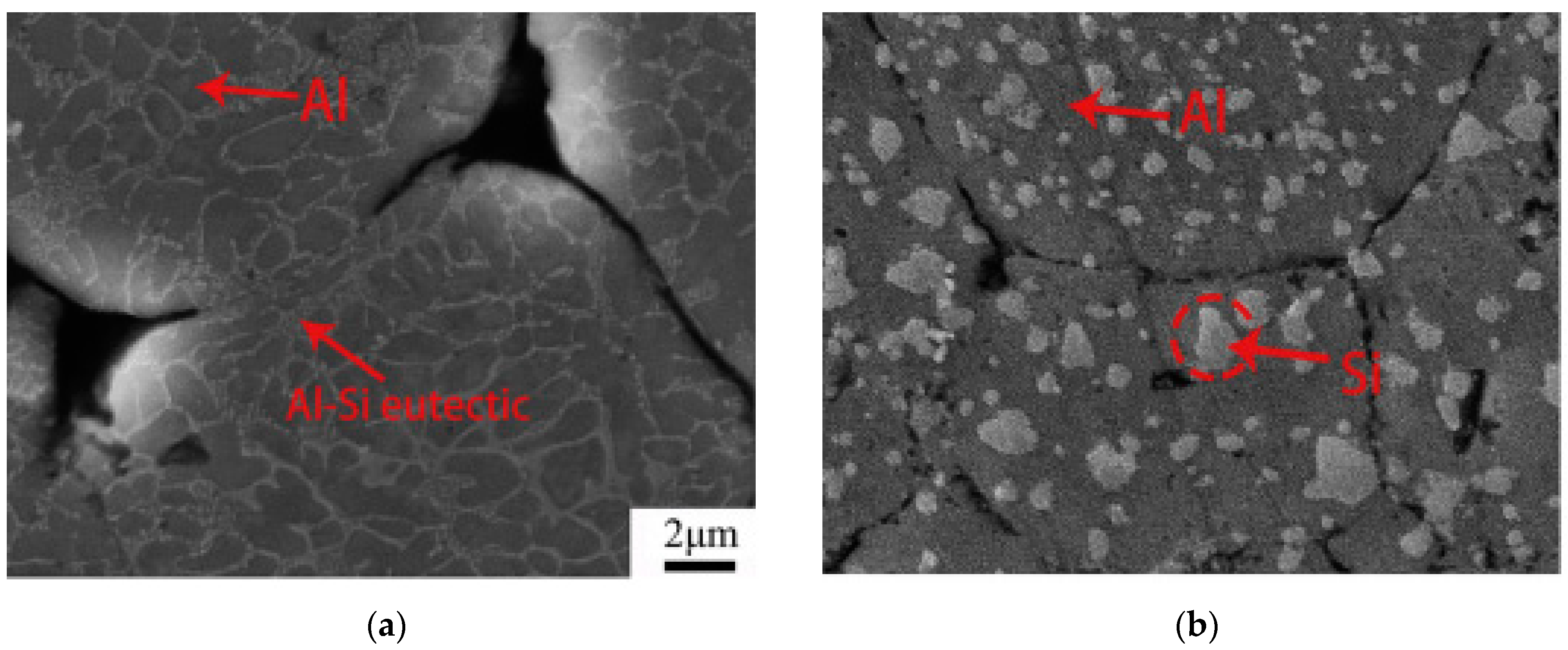
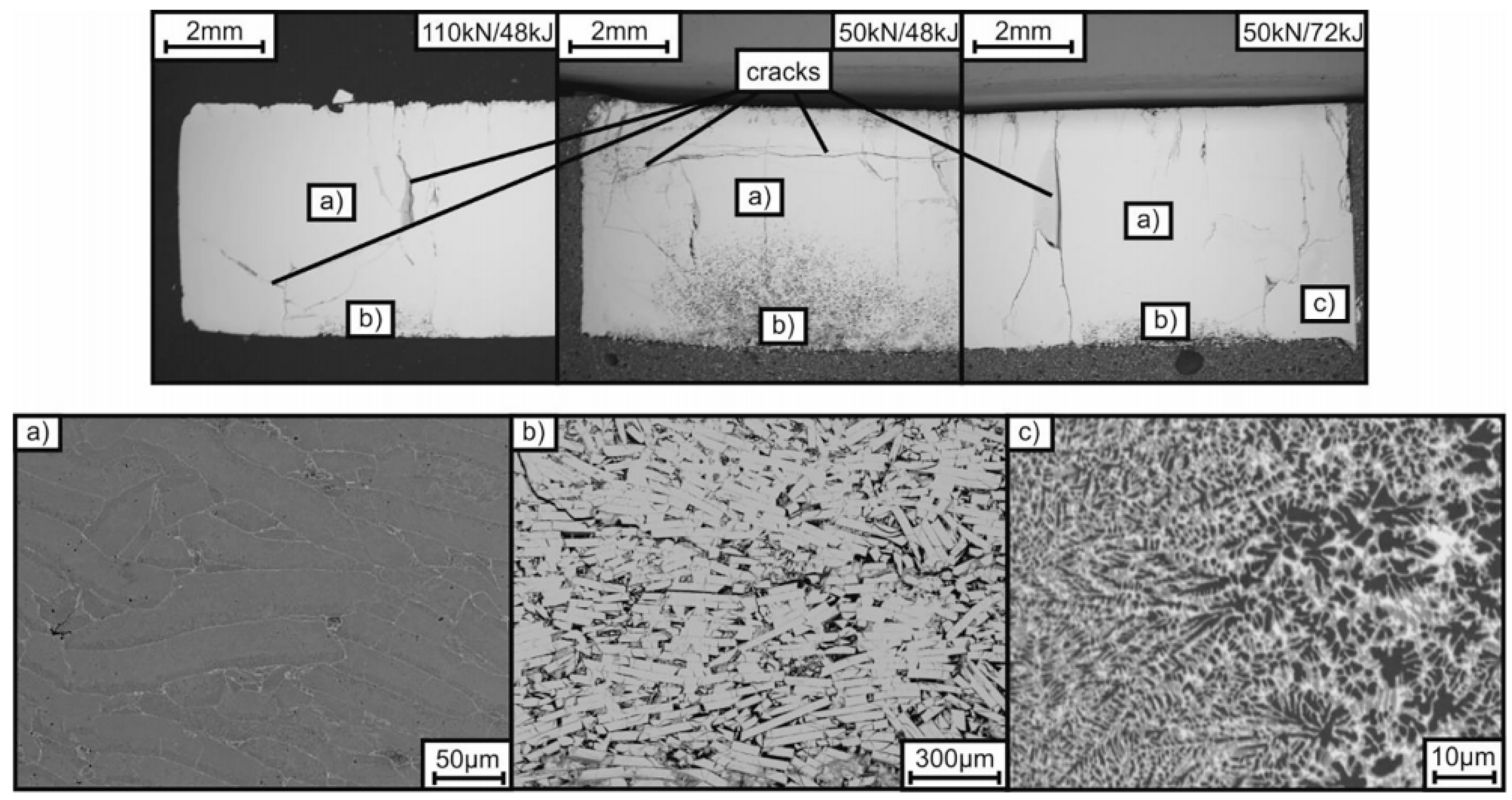
In a different study, Al-12Si powders were used [77]. Powders were processed after pressing at 550 MPa with an input energy of 3.15 kJ/g, achieving a relative density of 99.6%. The original microstructure, consisting of primary dendritic Al and eutectic Al-Si, could be maintained after EDC; for comparison, processing by SPS at 773 K for 10 min completely changed the original structure (See Figure 11). EDC compacts reached a hardness almost twice that of the SPS compacts, although a certain gradient was observed in radial direction. The centre of the compact presented lower hardness, then hardness increased in a ring, finally decreasing again in a small area near the die walls. The probable cause for this is the different work hardening caused by the inhomogeneous pressure field, and although the higher work hardening in the ring zone recovered during the EDC process, the hardness remained higher because of the precipitation strengthening effect of Si. Necking and grain boundaries were observed in the compact centre, whereas interlocking among particles resulting from integrated effects was observed in the high hardness ring.

4.3. Titanium-Base

Pure Ti powder has been processed by EDC after being pressed at 710 MPa (relative density of about 80%) with an energy of 2.04 kJ/g (400 V and 0.025 F), reaching a 90% relative density, which was not affected by using different powder particle sizes. The same final relative density was attained by pre-pressing at 425 MPa and discharging at 10 kV with 200 μF (5 kJ/g) [26]. Ti can however be consolidated with lower specific energy; as explained in [43], only 3.6 kJ/g were needed when pressure was applied at the time that the electric current passed through the compact.
For medical implants, pure Ti has also been consolidated. The use of 2.14 kJ/g under vacuum produced a solid core of deformed and welded particles and a porous layer of particles connected by necks, with a discharge time of about 122 µs. The process led to a compact where the original oxide layer breaks down, and a new very thin oxide layer is formed [55]. Different densities can be reached depending on the processing conditions, from fully porous parts to those with solid cores and porous periphery. The core size depends on the heat generated in the discharge, and the neck-joining particles can attain sizes in the order of 90 µm for particles of 200–250 µm, or 40 µm for particles of 50–100 µm (see Figure 1 and Figure 2). The obtained microstructure consisted of alpha prime, a non-equilibrium supersaturated structure produced by martensitic transformation from beta phase. Starting with a relative density of 39.7%, the process reached 72.8% after pressing the powders with a load of 10 kg (7.8 MPa) and sintering with 300 µF and 2.86 kJ/g [41]. The compressive strength can reach values as high as 280 MPa, greater than that of conventionally sintered Ti compacts, where the microstructure is clearly affected by grain growth and phase changes [37].
Ti porous parts have also been manufactured with spherical powders with sizes in the ranges of 160–200 µm and 315–400 µm (see Figure 12). The diameter of the particle necks was about 10–20% of the particle size, resulting in a porosity not less than 36–37%. Several parameters were analysed in this study. EDC with an energy of 1.8 J/mm3 showed that applied pressures in the range of 10–20 MPa provoke the destruction of the oxide films, making the resistivity to drop. The final porosity of the samples, the bending strength and the axial shrinkage behaves in a similar way, with minimum porosity and maximum strength and shrinkage in this pressure range. Higher pressures led to an increase of interparticle contacts, reducing resistivity and energy released for sintering. Regarding radial shrinkage, under low pressures of about 10 MPa, the pinch effect is dominating, producing a radial contraction of 5–9%, and higher for smaller particles. For pressures of 10–20 MPa, the contraction is reduced to 1–1.5% [42].
Despite the short discharge time, TiO2 surfaces transform to other titanium oxides during EDC, even during environmental discharges in a vacuum [55] or Ar atmosphere [37,41]. In addition, N2 atmosphere was used to intentionally change the powder’s surface composition, with the TiO2 surface of the as-received powders changing to TiN in the very short time that EDC lasts [109]. A similar effect is obtained when discharges are carried out in the air, revealing the formation of TiO2, and after a light etching, the presence of TiN and TiON [48].
Ti alloys have also been EDC-ed for medical purposes. Ti-6Al-4V has a similar behaviour to the previously described for pure Ti [39,72,107]. Dense cores of up to 2.37 mm in a 3.3 mm in diameter section were obtained by using 240 µF and 2.5 kJ/g in 1 g of sieved powder of 150–250 µm. In absence of axial pressure, the pinch effect is the only densification source, reaching an estimated value of 522 MPa in the column centre. Neck sizes between particles reached 55 µm and the pores were reduced to a mean value of 106 µm [39]. Studies by the same authors continued in South Korea with some different processing conditions regarding capacitance and input energy, and the use of vacuum [38] or argon atmosphere [45,112]. Results were similar regarding solid core size, neck size and maintaining the typical Widmanstätten alpha + beta microstructure.
The mechanical strength of Ti-6Al-4V parts was measured under different processing conditions, resulting in compressive yield strengths in the range of 328 to 523 MPa, and compressive ultimate strengths in the range of 420 to 600 MPa for powders processed in air with 1.5–2.5 kJ [110]. Yield strengths in the range of 18.5–435.6 MPa were measured for atomized powders (100–150 µm) subjected to discharges in argon of 1.07–2.86 kJ/g [114], therefore resulting in much higher values than the resistance of human teeth and conventionally sintered Ti dental implants [110]. A similar surface modification to that observed in pure Ti is observed in Ti-Al-V alloys, with the formation of TiO2, Ti2O3, TiN and TiC after sintering in air with 1.5 kJ [61], or just TiO2 and TiN for 1.43 kJ/g [113]. The use of vacuum atmosphere and 1.43 kJ/g only produced a light presence of TiO2 [111].
Other processed Ti alloys include the consolidation of MA Ti-Si37.5 powders, i.e., of intermetallic Ti5Si3 powders with interesting properties at high temperatures, trying to maintain the initial microstructure in the powders. Solid bulk materials with unaltered composition were consolidated without aid of external pressure by applying 17.5 or 20 kJ/g [115,116]. In addition, a mixture of Ti and Si powders at the stoichiometric ratio of Ti5Si3 were consolidated with 7.35 to 15.29 kJ/g. The process simultaneously alloyed and casted the original powders, obtaining the intermetallic compound with a relative density of 99% and a crystallite size of 120–151 µm. A calculated temperature of 5038 °C is likely to be enough to vaporize the powder mixture, but the short duration of the process, of about 129 µs, does only allow for the transformation into a liquid. On the other hand, the high pinch pressure, of up to 2900 MPa, pressurizes the liquid particles, eliminating porosity [40].
A similar study was carried out with 0.3 g of mixed [46] or MA [47] Ti-Al25 powders, processed under N2 atmosphere with 450 µF and input energies from 1.67 to 5 kJ/g. Both mixed and alloyed powders were completely transformed into bulk Ti3Al compacts. Mixed powders reached an estimated maximum temperature of 6192.8 °C, with a very fine microstructure (see Figure 13) leading to a hardness of 425 HV, versus typical values of 280 HV or 250 HV of casted and sintered compacts. Alloyed powders did not surpass the crystallite size of 100–350 nm. Processing under a N2 atmosphere transformed the TiO2 surface of both Ti3Al compacts into TiN.
Materials with prospective applications for hydrogen storage as the Ti-based quasicrystalline icosahedral phase in Ti-Ni-Zr alloys has also been processed by EDC, because of the shortness of the process and the metastability of this phase [117]. Processing Ti-28Zr-20Ni gas atomized powders, with two different particle size ranges, and input energies from 1.27 to 2.44 kJ/g, in vacuum, were studied. Powders in the range of 10–30 µm maintained the icosahedral phase only with 1.27 kJ/g, whereas bigger powder in the range of 30–50 µm withstood 1.55 kJ/g without phase evolution. This shows the heat generation dependence on the powder particle’s size, and the effect of the surface of the powder as a heat source.
An interesting study comparing EDC and SPS has been recently carried out with TiC-reinforced Ti composite [73]. Ti and up to 20 wt.% TiC powders were initially ball-milled, resulting TiC particles embedded on the Ti particles surface, with a crystallite size of about 40 and 55 nm for Ti and TiC, respectively. EDC was carried out with 0.7 g of powder, and specific energies of 2.14 to 3.57 kJ/g. Results showed compacts with a relative density of about 98.8%, where Ti particle boundaries were not identified and strip-like TiC particles were homogenously dispersed in the matrix. No reaction between matrix and reinforcement was observed. On the other hand, SPS compacts clearly showed Ti particles with TiC uniformly distributed along Ti particle boundaries (see Figure 14). Regarding mechanical properties, microhardness and nanoindentation increments of 653 HV and 6.5 GPa were measured with increasing TiC contents up to 20 wt.% in EDC compacts, whereas these values were about 67 HV and 0.7 GPa for SPS.

4.4. Nickel-Base

The first results on EDC of Ni powders can be found in [60]. These results served later to develop the equations governing the pinch pressure reached on the powder column or the temperature reached on particle contacts [35]. Experiments to confirm the calculated values were carried out on Ni powders oxidized at different levels, which allowed defining the different stages of the EDC process. Thus, with a capacitance of 240 μF and energies of up to 0.75 kJ/g, oxidized Ni powders of 100–150 μm with an oxide layer of 0.3 μm were consolidated. The oxide film was almost completely removed by EDC, and necks of about one tenth of the particle diameter were measured by electron microscopy. Pinch pressures were calculated between 11.8 and 26.5 MPa depending on the particle size, much lower than the yield strength of Ni of 138 MPa. The improvement in powder particle’s sintering came from the volume change due to the temperature increase and sublimation of Ni, which was calculated to generate pressures of approximately 4 GPa—enough to break the oxide layer. The analysis of compacted parts, however, showed almost no presence of nickel oxide, suggesting its dissociation into nickel and elemental oxygen. Some oxygen atoms can diffuse into metallic nickel particles to form small amounts of oxide particles in the particle boundaries.
Regarding Ni alloys, Ni-Ti shape memory alloys were processed by CDS, with pressure applied as a pulse superimposed on the electrical pulse [118,119]. The subjacent idea was avoiding the high reactivity and grain growth in casting methods of production, as well as avoiding modifying material properties in the post-casting processes. Input energies between 1.5 and 2.8 kJ/g were discharged on Nitinol powders with several end pressures between 200 and 360 MPa [118]. Measured relative densities were in the range of 94–100%, being higher for higher-applied energy and pressure during the sintering process. A porous external layer of 200–500 µm was found in consolidated parts because of the effect of cold electrodes and die, which can be removed by electropolishing. In its core, original particles were found after EDC with energies lower than 2 kJ/g; therefore, the liquid phase was not attained in the process. Higher energies led to a homogeneous and non-contaminated columnar oriented structure, with elongated band grains parallel to the loading axis. Moreover, the biocompatibility of the sintered materials was evaluated regarding Ni ions release, which is directly correlated to the biocompatibility of NiTi alloys. The amount of released Ni ions from sintered sample surfaces was almost negligible, with excellent cytocompatibility towards fibroblasts. The study of similarly processed Ni-Ti alloys was completed with microstructural analysis after heat treatment and annealing, at 800–900 °C for 1 h, and ageing, at 505–525 °C for 2 min [119]. Results showed a moderate grain growth, preserving the grain refinement effect of ESF.

4.5. Cooper-Base

Cu powders with different thicknesses of the oxide layer surrounding powder particles have been used to study the effect of EDC. Powder batches with different average sizes of 106, 60 and 43 µm were oxidized in air at temperatures of 150, 200 and 250 °C, and subjected to electrical discharges from 79.8 µF with energies of up to 5.75 kJ/g [62]. Oxide thickness reached up to 2.1 µm in the bigger Cu particles. Breakdown voltages for a 100 mm in length and 7.4 mm in diameter column were measured, resulting in values between 1 and 6 kV for the smaller batch, and some narrower values for bigger particles. Nevertheless, the interparticle breakdown voltage, computed by dividing the measured breakdown voltage by the number of particles necessary to reach the column height, was almost independent of the particle size, just depending on the oxide thickness.
The effect of consolidation on the microstructure was studied on ball-milled nanocrystalline Cu powders [120,121]. Milled powders had a plate like shape with a diameter of 30–40 µm and thickness of 5–15 µm [120], and estimated grain size of 38 nm [120], or a crystallite size of 28 nm measured by XRD, with a dislocation density of 1.8 × 10¹⁶ m−2 [121]. The study was intended to check the results observed in Fe-based alloys, where ultrafast processes such as EDC maintain the original structure even at the level of grain misorientation and dislocation interaction. Consolidation was carried out on 2 g of powder with 3.1 kJ/g under a pressure of 350 [120] or 300 MPa, with specimens subsequently deformed under compression of up to 650 MPa [121]. After sintering, 93% of theoretical density was measured. Vickers microhardness values around 182 ± 12 HV were measured, with limited change in the nanostructure: crystallite size well below 100 nm when starting from 38 nm [120], and a measured crystallite size of 38 nm when starting from 28 nm [121]. The dislocation density is halved, resulting close to 10 × 1016 m−2 [120], or slightly diminished, with absence of networks of strongly interacting dislocations [121].
A similar study was carried out on the Cu alloy Cu-37.5Zn. Cold worked bulk parts consisting of a single fcc α–Cu(Zn) coarse grained phase, with a lattice parameter of 0.3702 nm, were treated by EDC with 1200 µF at 1.8 kV, i.e., an energy of 1.9 kJ in a piece of 30.6 mm3. After discharging, coarse grains with an fcc structure were still observed, with most of the dislocation arrays becoming parallel, and fewer dislocation nodes. Moreover, nanostructured areas of about 11 nm accounting for about 5–10% of the material, with phases α –Cu(Zn) and β’–(CuZn), were observed. A temperature increase of up to 670 °C was estimated in areas with high density of defects, transforming the original non-equilibrium supersaturated solid solution [76].
Regarding studies with other Cu alloys, Cu-15Sn alloy obtained by mixing Cu-25Sn alloy and pure Cu, was poured in a die with a cross section of 3 × 4 mm2 until filling a high of 100 mm. After ESF processing, densities higher than 98% were attained, with coarser grains at the periphery and a centre with a much finer microstructure. Samples were subsequently cold rolled with a maximum thickness reduction of 61.33%. According to the Cu-Sn phase diagram, α-Cu and Sn rich ε-phase are present, together with grains of admixed Cu. Thus, the EDC process did not affect the chemical composition nor the microstructure of the constituents, resulting in a fine microstructure with higher mechanical properties than the obtained with conventional processing techniques. Bars could be cold rolled without breaking, although a significant strain hardening was detected [86].
Additionally, a powder blend of pure ball-milled Cu and 5 wt.% synthetic diamond coated with Ni film, with sizes of 3 and 350 µm, were processed with 4.12 kJ under a pressure of 125 MPa with a total duration of 150 ms. The goal was to avoid graphitization of diamond crystals with this short process and maintain the ultrafine structure of Cu, at the time that compressive residual stresses were generated in the compact. A complete FEM model was developed in this work to avoid the trial and error process [52].
The evolution of amorphous powders has also been studied in Cu based materials. Gas atomized amorphous powders of composition Cu-22Zr-18Ti-6Ni were consolidated with 0.22–1.55 kJ/g in vacuum. Compacts of 3 and 4 mm in diameter were EDC-ed without external applied pressure. The amorphous character was maintained up to 0.44 kJ/g in compacts of 3 mm in diameter, reaching a relative density of about 55% and forming necks between particles, with pores homogeneously distributed in the sample. Increasing energy to 0.66 kJ/g made the powders crystalize and relative density reached 80%, whereas 1.11 kJ/g made a dense sample with few pores appear (see Figure 15). Regarding samples with 4 mm, the amorphous character is maintained up to 1.1 kJ/g, whereas increasing to 1.55 kJ/g makes a crystalline pore-gradient structure appear [122]. Details on the microstructural evolution inside powder particles of similarly manufactured compacts can be found in [123]. Being in the energy limit for crystallization, crystalline phases are mainly observed in the outer layer of big particles, with the inner zone maintaining the amorphous structure. Small particles are completely crystallized. For higher energies, particles completely crystallize, with coarse grains in the inner areas and fine crystalline phases in the surface. This reveals a complete melt and a quicker quench at surfaces.
Sintering with applied pressures in the range 250–1000 MPa and a maximum energy of 40 kJ (3400 µF and up to 5 kV) were conducted on 10–30 µm Cu powder, Cu mechanically mixed with 40 vol.% TiB2 30–100 nm in size, and Cu containing Ti and B powder in the same proportion. Sintering succeeded with Cu powder for an integrated value of the square of the current density higher than 1.4 × 10¹⁵ A2·s/m4, a value lower than that corresponding to the copper transition to the liquid state, of 1.05 × 10¹⁷ A2·s/m4. The height of the sample decreased by 25–30%, and the transverse size remained unchanged, obtaining high-density materials. Sintering succeeded for Cu-TiB2 from 0.9 × 10¹⁵ A2·s/m4, and from 0.34 × 10¹⁴ A2·s/m4 for the Cu-Ti-B powder. This latter lower value can be explained by the additional heat due to an exothermal reaction of TiB2 synthesis as confirmed by XRD with a crystallite size smaller than 20 nm. Despite the porous structure of the Cu-TiB2 materials, their electric erosion resistance was four times higher than that of solid copper [64].

4.6. Hard Metals

Consolidation of hard metals by EDC has been tested by several researchers. WC-20Co powders with WC grain size <5 µm were successfully processed by applying an external pressure of 200 MPa and a current density of up to 95 kA/cm2 [90]. Relative density of up to 99% was attained at the time that maintaining the WC size and a hardness of 78 ± 2 HRA was measured (see Figure 16). Higher current densities caused the disintegration of the material, creating big pores and reducing hardness to 46 ± 6 HRA.
For certain applications, attaining a nanostructured WC is considered a key factor to obtain high hardness and fracture toughness. Nanocrystalline WC-10Co powders have been processed by EDC, showing that powders can be consolidated into ultrafine-grained WC-Co cemented carbides with outstanding mechanical properties [124]. Processing 2.5 g of WC-Co powders with particle size of about 200 nm and average grain size of 50 nm, under 300 MPa of external pressure and 360 µF at 3 kJ/g, reached 95% of theoretical density at the time that avoided the grain growth of WC.
Outstanding properties can also be obtained in graded hard metals, regarding both cobalt content and WC grain size. Graded materials are difficult to process by traditional liquid phase sintering, although good results can be obtained with quick enough processes to restrict Co migration and WC growth. Nanocrystalline and coarse-grained WC-10Co powders, 50 nm and 3 µm, respectively, were consolidated in a two-layer compact by EDC with 360 µF and current densities in the range 150 to 240 kA/cm2 [125]. Different WC grain sizes produce liquid channels of different size during conventional sintering, being smaller for finer grains, with preferential Co migrating to these areas due to the capillary force. During EDC experiments, an increase in Co content to about 14 wt.% was observed only in 15 µm of the fine-grained layer. On the other hand, grain growth is constrained with EDC since the densification mainly comes from particle rearrangement (see Figure 17). Regarding mechanical properties, the ultrafine grained layer showed higher hardness of about 18 GPa, whereas the coarse layer exhibited higher fracture toughness of about 14 MPa·m1/2, producing graded cemented carbides with excellent properties combination. The interfacial diffusion between sublayers in EDC has also been studied in WC-11Co/Fe/WC-11Co compacts [50]. The distance of Fe penetration reached 400 µm for a current density of 220 kA/cm2 attained with 6.48 kJ/g. This value agrees with estimations for the particle rearrangement densification mechanism, therefore being restricted the grain growth by solution-reprecipitation.
Additionally, graded Fe/W composites for future applications in fusion reactors have been processed by low voltage EDC [88]. Fine powders of Fe and W were mechanically mixed in different volume fractions until particles big enough to be used safely were attained. Powders containing different volume fractions of W, from 0 to 75%, were loaded into the die in different sublayers and consolidation was carried out with up to 388 MPa and 80 kJ (applied to a powder volume of 850 mm3). No differences were found with respect to compacts of homogeneous compositions, with little porosity, fine distribution of Fe and W volumes, and bond zones between sublayers not showing more defects than other locations of the microstructure. The compact’s thermal conductivity is higher than or equal to the conductivity of Eurofer—a promising property to remove heat. The Young’s modulus is somewhat lower than expected according to a linear interpolation model, as the yield and bending strengths are than predicted. Finally, the powdered structure was electrically sintered to a polished 1 mm thick vanadium disk (see Figure 18). Joining cemented carbide to bulk materials is usually carried out by the brazing and electron beam welding processes, but EDC has also been proved with bulk steel [90]. By using EDC with 200 MPa and a current density of 100 kA/cm2 joints resulted homogeneous, with high strength and low residual thermal stress, therefore resulting in an alternative joining process with high precision and low heat input.
Samples of W-6.93Ni-3.12Fe were prepared by EDC from mechanically mixed near spherical powders with an average size of 6.03 μm. Voltage varied from 4.5 to 5.8 kV and pressure from 100 to 250 MPa. Mechanical tests (Brazilian test) of the consolidated cylindrical samples showed that higher external pressures resulted in lower strengths, with samples consolidated at 250 MPa resulting in a brittle fracture. The maximum strength (500 MPa) of samples sintered at 200 MPa was reached by consolidating with 5.4 kV, decreasing for higher voltages. Even higher strength of 700 MPa was reached with 150 MPa at 5.5 kV [84].
The pore formation mechanism during EDC has been studied in W powders [123]. The surfaces of broken W compacts fabricated with spherical and smooth-surface powders revealed the presence of needle like shapes and rough powder surfaces. This means that melting, evaporation and quenching processes took place during EDC because of the joule heat produced by the current flow (see Figure 19). Moreover, the pinch pressure affected the interparticle necks, with unstable necks at 1.5 kJ/g and more stable necks for higher energies [123].
Discharge sintering of hard metal cutting tools, consisting of WC powders of 1 μm mixed with TiC powders of 2 μm and iron-nickel atomized or ball-milled powders, was carried out [126]. Obtained samples (WC-TiC26-43-60-100-Co14), and commercial grade P20 material (WC-TiC32.3-Co12.7) for comparison, were used to perform a finishing operation on an 18NiCrMo4 type steel in normalized state. EDC samples reached 95–97.3% relative density with hardness and indentation fracture toughness higher than the commercial material (the best combination 1780 HV30 and 21 MPa·m1/2 for WC and TiC contents of 43 vol.%). The sintering process did not alter the carbide’s size. Regarding wear results, an increase of 30% of contact time was obtained with a composition analogous to the commercial P20. Even an increase of 100% of contact time was obtained when using the tungsten free, pure TiC, cermet characterized by a hardness of 1613 HV30 and toughness of 18 MPa·m1/2.
Finally, electrical discharges were applied to powder suspensions of (WC-6Co)-1ASUD75 diamond composite powders to refine the powder’s structure [80]. Discharges in aqueous suspension with a total energy of 400 kJ/dm3 significantly influences the structure. Agglomerated diamond powders with sizes in the range from 1.8 to 21.31 µm changed to a bimodal distribution varying from 0.65 to 20 µm.

4.7. Other Compositions

Several other compositions have been consolidated by EDC. Regarding Co alloys, amorphous Co-4Fe-1Ni-14Si-15B alloy powders were initially pressed up to a relative density of 75%, and then processed with input energy bellow 0.53 kJ/g to maintain the amorphous structure. The relative density increased about 12% reaching a homogeneous amorphous structure [69].
High corrosion-resistant Zr-1Nb alloy powders with both flake and spherical shape were processed by EDC to form bulk samples and coatings. Different current densities were needed to reach the maximum density, depending on the applied pressure. For flake particles, about 180 kA/cm2 was the best condition for pressures of 165 and 190 MPa, whereas was 280 kA/cm2 for 307 MPa. For current densities above 340 kA/cm2, the final density decreases sharply. The microstructures for both flake and spherical particles were maintained after consolidation. Regarding coatings, a high-strength damage-free interface is obtained for coatings on both ceramic and metallic substrates [127].
Low melting temperature materials have also been consolidated with low energy conditions. In total, 1.5–2 g of Sn or Zn powders with different particle sizes were pressed at 70–710 MPa and discharged with 400 V and 0.025 F (0.90 kJ/g for Sn and 1.38 kJ/g for Zn). Density increased to high values by applying high pressure. Sn density increased from 7.2 to 7.3 g/cm3 after discharging. In general, no individual particles could be seen in the microstructures after consolidation. New discharges on the same compact did not improve densification [26].
Low energy discharges have also been applied to sinter Ag-Ni nanocomposite paste for thermoelectric element interconnections. The paste was prepared from 75 nm Ag and Ni particles and additives, and bridged two silver electrodes on Al2O3 substrate. After drying and compressing the paste at 2.4 MPa, a current from a capacitor 0.01 F charged to 10 V sinters the sample. The result is a resistance decrease by nearly 1–2 orders of magnitude [78].
The CDS process has also been applied to high karatage 24 and 18 k Au powders, even mixed with 15 vol.% nanodiamonds [92]. The underlying idea is attaining a high hardness material, easy to polish at the time that resistant to wear and scratch. Both 24 and 18 k powders reached a relative density over 98.5% after sintering, with microhardness of up to 80 HV and 180 HV, respectively, and reaching 220 HV when alloyed with nanodiamonds. Even 280 HV was attained in ball-milled nanostructured 18 k Au. These values resulted higher than 60 HV for microalloyed as-cast Au or 150 HV for 18 k Au in the soft-annealed state, mainly because of the effective dispersion of the alloying element and to the small grain size after electrical sintering.
UN for nuclear applications has been processed by EDC [97]. Pressures varied from 160 to 210 MPa and applied voltage from 2 to 3 kV, reaching a maximum relative density of 96% and maintaining the initial particles size.
Melt-spun Nd-Fe-B flakes, about 30 µm thick and size from a few µm to a few mm, with nanocrystalline microstructure, were processed with 4 to 7.2 kJ/g and 176 to 388 MPa. As shown in Figure 20 different microstructures were achieved depending on the processing parameter and compact zone, the latter because of the different temperature reached in different zones. The dense zone is formed through a liquid phase enriched in Nd that penetrates into gaps. The remelted zone is a dendritic microstructure formed by fast solidification after melting, mainly associated to high energy discharges or low compacted areas. Optimized magnets are obtained by using high pressures 317–388 MPa and moderate discharge energy of 4–4.8 kJ/g [128].
Nanocrystalline MA Nb-Al23 powders were consolidated with external pressures of up to 450 MPa [129] or 500 MPa [71]. The annealed powders at relative densities of up to 85% were discharged with input energies of 0.5, 0.75 and 1.0 kJ/g [129], or 1 and 2 kJ/g [71], from a 500 µF capacitor bank. The maximum achieved relative density was 99% for highest input energies. The microstructure for low energies remained without significant changes, with just a very small grain growth. Higher energies produced the transformation from Nb, Al, Nb2Al and Nb3Al to only the compound phases, and the increase in the latter one. Grain size grew from 5–8 to a maximum of 26–36 nm, with extremely high hardness values of 14.7–17.6 GPa.

5. Conclusions

According to the different studies reviewed in this manuscript, the electrical consolidation of powders by discharging the energy stored in a capacitor can be applied to a wide variety of metallic materials, from pure elemental powders to complex alloys. In general, the very short duration of the process allows for maintaining the microstructure of the original powders, even when working with nanostructured materials or amorphous structures.
The process is governed by several factors affecting the easiness of electricity to flow through the powder mass. A key factor regarding this flow is the electrical resistance of the powders, affected by the oxide layers surrounding the particles. Oxide layers can be eliminated by the appropriate combination of pressure (external or due to the electromagnetic forces of the process) and energy of the process, with a different effect of capacitance and voltage. Nevertheless, the presence of this oxide layer is mandatory for the process, and has to be eliminated during the process itself, not previously to the discharge. Thus, the necessary heat to join the powder particles is generated by Joule effect.
When using the proper parameters, a homogeneous microstructure can be attained, with densities near the theoretical ones, and just a small layer in contact with the electrodes and die being not properly consolidated. Nevertheless, graded materials regarding porosity can also be obtained, mainly when the pinch effect controls the pressure during the process. The processing conditions and the attained results very much depend on the studied materials, because the powder characteristics can be quite different, therefore being necessary different operating parameters.
On the other hand, electrical discharging is an uncontrolled process, with the current intensity not being regulated and varying during the process. This makes the temperature uncontrollable inside the specimen to be consolidated. Only the proper selection of the processing conditions (which must be found by trial and error) will drive to acceptable results. A detailed simulation of the process, in the line of the work in [51,52] (also statistical analysis of big amounts of results can help, as shown in [102]) is still lacking. Advances in this direction could help understanding of and finding the best processing conditions for a particular material, and the reason for the very different conditions which are adequate for different materials. Any progress in this line would help to order the large amount of experimental results obtained up to now. The basic problem is the difficulty in simulating a process in which mechanical, electrical and thermal problems are intimately coupled, with the added problem of the very short time that the process lasts.
The stored energy used in experiments is quite different for different materials, with a mean value of about 3 kJ/g. This energy is attained with capacitors of a few hundred μF and charging voltages of a few kV. The external applied pressure ranges from zero to hundreds of MPa. There are not however, as already commented, clear value ranges for particular compositions, making it necessary to look for the appropriate combination of the process parameters to find the optimal experimental conditions. The differences in reported values of the process parameters among different researchers does not help in defining the aforementioned optimal conditions for the different materials.
The process has usually been applied to cylindrical small pieces, with a maximum diameter of about 20 mm. In this scale, the process generates promising results in most experiences studied, with improved properties mainly associated with the final microstructure obtained in the consolidated pieces. For metallic materials, one of the main challenges of EDC is its application to bigger and complex shaped compacts. This challenge will require studies by trial and error. Only a better understanding of the physical phenomena taking place during the process, and a correct modelling without simplifications, considering a uniform porosity in the compact for each particular moment of the process, will help in a higher applicability of the technique.
The limited applicability to conductive materials should also be addressed by extending the use to semiconductors heated to increase their conductivity. This is the idea underlying at microwave or flash sintering processes. Nevertheless, increasing temperature could easily affect the final microstructures, and therefore each particular case should be analysed.

Author Contributions

Conceptualization, F.G.C., J.M.M. and S.L.-P.; investigation, R.M.A. and F.T.; writing—original draft preparation, R.M.A. and F.T.; writing—review and editing, F.G.C., J.M.M. and S.L.-P. All authors have read and agreed to the published version of the manuscript.

Funding

This research was funded by Ministerio de Economía y Competitividad (Spain) and Feder (EU) through the research projects DPI2015-69550-C2-1-P and DPI2015-69550-C2-2-P.

Conflicts of Interest

The authors declare no conflict of interest.

References

  1. Akinwamide, S.O.; Abe, B.T.; Akinribide, O.J.; Obadele, B.A.; Olubambi, P.A. Characterization of microstructure, mechanical properties and corrosion response of aluminium-based composites fabricated via casting—A review. Int. J. Adv. Manuf. Technol. 2020, 109, 975–991. [Google Scholar] [CrossRef]
  2. Weiler, J.P. A review of magnesium die-castings for closure applications. J. Magnes. Alloys 2019, 7, 297–304. [Google Scholar] [CrossRef]
  3. Chandrasekaran, M. Forging of metals and alloys for biomedical applications. In Metals for Biomedical Devices, 2nd ed.; Niinomi, M., Ed.; Woodhead Publishing Series in Biomaterials; Woodhead Publishing: Duxford, UK, 2019; pp. 293–310. [Google Scholar]
  4. Camacho, K.E.; Saavedra, J.J.; Salvatierra, Y.; Quispe, G.W. Lean manufacturing application in the laminating machine manufacturing process in a metalworking company. In Proceedings of the 5th Brazilian Technology Symposium, Campinas, Brazil, 22–24 October 2019; Iano, Y., Arthur, R., Saotome, O., Kemper, G., Padilha, R., Eds.; Springer: Cham, Switzerland, 2021; Volume 201. [Google Scholar]
  5. Henneberg, J.; Merklein, M. Investigation on extrusion processes in sheet-bulk metal forming from coil. Cirp J. Manuf. Sci. Technol. 2020, 31, 561–574. [Google Scholar] [CrossRef]
  6. Li, J.; Laghari, R.A. A review on machining and optimization of particle-reinforced metal matrix composites. Int. J. Adv. Manuf. Technol. 2019, 100, 2929–2943. [Google Scholar] [CrossRef]
  7. Rodriguez-Contreras, A.; Punset, M.; Calero, J.A.; Gil, F.J.; Ruperez, E.; Manero, J.M. Powder metallurgy with space holder for porous titanium implants: A review. J. Mater. Sci. Technol. 2021, 76, 129–149. [Google Scholar] [CrossRef]
  8. Childerhouse, T.; Jackson, M. Near net shape manufacture of titanium alloy components from powder and wire: A review of state-of-the-art process routes. Metals 2019, 9, 689. [Google Scholar] [CrossRef] [Green Version]
  9. Tan, Z.Q.; Engström, U.; Li, K.; Liu, Y. Effect of furnace atmosphere on sintering process of chromium-containing steel via powder metallurgy. J. Iron Steel Res. Int. 2021, in press. [Google Scholar] [CrossRef]
  10. Tuncer, N.; Bose, A. Solid-state metal additive manufacturing: A review. JOM 2020, 72, 3090–3111. [Google Scholar] [CrossRef]
  11. Lux, J. Improved Manufacture of Electric Incandescent Lamp Filaments from Tungsten or Molybdenum or an Alloy Thereof. GB Patent 27,002, 13 December 1906. [Google Scholar]
  12. Weintraub, G.; Rush, H. Process and Apparatus for Sintering Refractory Materials. U.S. Patent 1,071,488A, 26 August 1913. [Google Scholar]
  13. Taylor, G.F. Apparatus for Making Hard Metal Compositions. U.S. Patent 1,896,854, 7 February 1933. [Google Scholar]
  14. Lenel, F.V. Resistance sintering under pressure. JOM 1955, 7, 158–167. [Google Scholar] [CrossRef]
  15. Grasso, S.; Sakka, Y.; Maizza, G. Electric current activated/assisted sintering (ECAS): A review of patents 1906–-2008. Sci. Technol. Adv. Mater. 2009, 10, 1–24. [Google Scholar] [CrossRef]
  16. Olevsky, E.A.; Dudina, D.V. Field Assisted Sintering, Science and Applications; Springer Nature Switzerland AG: Cham, Switzerland, 2018. [Google Scholar]
  17. Almeida Costa Oliveira, F.; Granier, B.; Badie, J.M.; Cruz Fernandes, J.; Guerra Rosa, L.; Shohoji, N. Synthesis of tungsten sub-carbide W2C from graphite/tungsten powder mixtures by eruptive heating in a solar furnace. Int. J. Refract. Met. Hard Mater. 2007, 25, 351–357. [Google Scholar] [CrossRef]
  18. Mondal, A. Microwave Sintering of Metals: Modelling of Microwave Heating of Particulate Metals and Its Application in Sintering of Tungsten-Based Alloys; Lambert Academic Publishing GmbH & Co. KG: Saarbrücken, Germany, 2011. [Google Scholar]
  19. Guillon, O.; Gonzalez-Julian, J.; Dargatz, B.; Kessel, T.; Schierning, G.; Räthel, J.; Herrmann, M. Field-Assisted Sintering Technology/Spark Plasma Sintering: Mechanisms, Materials, and Technology Developments. Adv. Eng. Mater. 2014, 16, 830–849. [Google Scholar] [CrossRef]
  20. Ariane, M.; Balima, F.; Barthelemy, F. Spark Plasma Sintering: Current Status, New Developments and Challenges. A Review of the Current Trends in SPS; Cao, G., Estournès, C., Garay, J., Orrù, R., Eds.; Elsevier: Amsterdam, The Netherlands, 2019. [Google Scholar]
  21. Montes, J.M.; Cuevas, F.G.; Ternero, F.; Astacio, R.; Caballero, E.S.; Cintas, J. Medium-frequency electrical resistance sintering of oxidized C.P. iron powder. Metals 2018, 8, 426. [Google Scholar] [CrossRef] [Green Version]
  22. Montes, J.M.; Cuevas, F.G.; Cintas, J.; Urban, P. A One-Dimensional Model of the Electrical Resistance Sintering Process. Metall. Mater. Trans. A Phys. Metall. Mater. Sci. 2015, 46, 963–980. [Google Scholar] [CrossRef]
  23. Urban, P.; Ternero, F.; Caballero, E.S.; Nandyala, S.; Montes, J.M.; Cuevas, F.G. Amorphous Al-Ti powders prepared by mechanical alloying and consolidated by electrical resistance sintering. Metals 2019, 9, 1140. [Google Scholar] [CrossRef] [Green Version]
  24. Cuevas, F.G.; Andreouli, D.; Gallardo, J.M.; Oikonomou, V.; Cintas, J.; Torres, Y.; Montes, J.M. Ceramic dies selection for electrical resistance sintering of metallic materials. Ceram. Int. 2019, 45, 14555–14561. [Google Scholar] [CrossRef]
  25. Yurlova, M.S.; Demenyuk, V.D.; Lebedeva, L.Y.; Dudina, D.V.; Grigoryev, E.G.; Olevsky, E.A. Electric pulse consolidation: An alternative to spark plasma sintering. J. Mater. Sci. 2014, 49, 952–985. [Google Scholar] [CrossRef]
  26. Rajagopalan, P.K.; Desai, S.V.; Kalghatgi, R.S.; Krishnan, T.S.; Bose, D.K. Studies on the electric discharge compaction of metal powders. Mater. Sci. Eng. A 2000, 280, 289–293. [Google Scholar] [CrossRef]
  27. Grigoryev, E.G.; Olevsky, E.A. Thermal processes during high-voltage electric discharge consolidation of powder materials. Scr. Mater. 2012, 66, 662–665. [Google Scholar] [CrossRef]
  28. Grigoryev, E.G.; Olevsky, E.A.; Yudin, A.V.; Yurlova, M.S. Wave mode high voltage consolidation of powder materials. Comput. Mater. Sci. 2015, 100, 8–14. [Google Scholar] [CrossRef]
  29. Darvizeh, A.; Alitavoli, M.; Namazi, N. On the effects of circuit parameters on electrical behaviour of metallic powders subjected to high rate discharge compaction process. Powder Metall. 2020, 63, 94–103. [Google Scholar] [CrossRef]
  30. Evans, U.R. The Corrosion and Oxidation of Metals: First Supplementary Volume; Edward Arnold: London, UK, 1968. [Google Scholar]
  31. Montes, J.M.; Cuevas, F.G.; Cintas, J. Electrical resistivity of metal powder aggregates. Met. Mater. Trans. B 2007, 38, 957–964. [Google Scholar] [CrossRef]
  32. Garino, T.J. Electrical Behavior of Oxidized Metal Powders during and after Compaction. J. Mater. Res. 2002, 17, 2691–2697. [Google Scholar] [CrossRef]
  33. Montes, J.M.; Cuevas, F.G.; Cintas, J.; Gallardo, J.M. Electrical conductivity of metal powder aggregates and sintered compacts. J. Mater. Sci. 2016, 51, 822–835. [Google Scholar] [CrossRef]
  34. Montes, J.M.; Cuevas, F.G.; Cintas, J. Electrical resistivity of a titanium powder mass. Granul. Matter 2011, 13, 439–446. [Google Scholar] [CrossRef]
  35. Kim, D.K.; Pak, H.R.; Okazaki, K. Electrodischarge Compaction of Nickel Powders. Mater. Sci. Eng. A 1988, 104, 191–200. [Google Scholar] [CrossRef]
  36. Clyens, S.; Al-Hassini, S.T.S.; Johnson, W. The compaction of powder metallurgy bars using high voltage electrical discharges. Int. J. Mech. Sci. 1976, 18, 37–44. [Google Scholar] [CrossRef]
  37. Jo, Y.H.; Kim, Y.H.; Jo, Y.J.; Seong, J.G.; Chang, S.Y.; Reucroft, P.J.; Kim, S.B.; Lee, W.H. Self-Consolidation Mechanism of Porous-Surfaced Ti Implant Compacts Induced by Electro-Discharge-Sintering of Spherical Ti Powders. Met. Mater. Int. 2015, 21, 337–344. [Google Scholar] [CrossRef]
  38. Lee, W.H.; Hyun, C.Y. Fabrication of fully porous and porous-surfaced Ti-6Al-4V implants by electro-discharge-sintering of spherical Ti-6Al-4V powders in an one-step process. J. Mater. Process. Technol. 2007, 189, 219–223. [Google Scholar] [CrossRef]
  39. Lee, W.H.; Puleo, D.A. Mechanism of consolidation of a porous-surfaced Ti-6Al-4V implant formed by electrodischarge compaction. J. Mater. Sci. Lett. 1999, 18, 817–818. [Google Scholar] [CrossRef]
  40. Chang, S.Y.; Cheon, Y.W.; Yoon, Y.H.; Kim, Y.H.; Kim, J.Y.; Lee, Y.K.; Lee, W.H. Self-consolidation mechanism of Ti5Si3 compact obtained by electro-discharge-sintering directly from physically blended Ti-37.5 at.% Si powder mixture. Arch. Met. Mater. 2017, 62, 1299–1302. [Google Scholar] [CrossRef] [Green Version]
  41. An, Y.B.; Lee, W.H. Synthesis of porous titanium implants by environmental-electro-discharge-sintering process. Mater. Chem. Phys. 2006, 95, 242–247. [Google Scholar] [CrossRef]
  42. Dzmitry, M.; Klimenty, B. A porous materials production with an electric discharge sintering. Int. J. Refract. Met. Hard Mater. 2016, 59, 67–77. [Google Scholar] [CrossRef]
  43. Fais, A. Processing characteristics and parameters in capacitor discharge sintering. J. Mater. Process. Technol. 2010, 210, 2223–2230. [Google Scholar] [CrossRef]
  44. Fais, A. Fundamental Aspects of Capacitor Discharge Sintering: Theory and Applications. Ph.D. Thesis, Politecnico di Torino, Torino, Italy, 2008. [Google Scholar]
  45. Lee, W.H.; Jo, Y.J.; Kim, Y.H.; JO, Y.H.; Seong, J.G.; Van Tyne, C.J.; Chang, S.Y. Self-consolidation mechanism of porous Ti-6Al-4V implant prototypes produced by electro-discharge-sintering of spherical Ti-6Al-4V powders. Arch. Metall. Mater. 2015, 60, 1185–1189. [Google Scholar] [CrossRef] [Green Version]
  46. Jang, H.; Cho, Y.; Kang, T.; Kim, K.; Lee, W. A Study on the Synthesis and Consolidation of Ti3Al by Electro-Discharge. J. Kor. Inst. Met. Mater. 2009, 47, 488–493. [Google Scholar]
  47. Chang, S.Y.; Jang, H.S.; Yoon, Y.H.; Kim, Y.H.; Kim, J.Y.; Lee, Y.K.; Lee, W.H. Self-consolidation and surface modification of mechanical alloyed Ti-25.0 at.% Al powder mixture by using an electro-discharge technique. Arch. Met. Mater. 2017, 62, 1293–1297. [Google Scholar] [CrossRef] [Green Version]
  48. Jo, Y.J.; Yoon, Y.H.; Kim, Y.H.; Chang, S.Y.; Kim, J.Y.; Lee, Y.K.; Van Tyne, C.J.; Lee, W.H. Surface modification of self-consolidated microporous Ti implant compacts fabricated by electro-discharge-sintering in air. Arch. Met. Mater. 2017, 62, 1287–1291. [Google Scholar] [CrossRef] [Green Version]
  49. Belyavin, K.E.; Min’ko, D.V.; Kuznechik, O.O. Modeling of the process of electric-discharge sintering of metal powders. J. Eng. Phys. Thermophys. 2004, 77, 628–637. [Google Scholar] [CrossRef]
  50. Wu, X.; Guo, J. Effect of liquid phase on densification in electric-discharge compaction. J. Mater. Sci. 2007, 42, 7787–7793. [Google Scholar] [CrossRef]
  51. Maizza, G.; Tassinari, A. Modelling of Micro/Macro Densification Phenomena of Cu Powder during Capacitor Discharge Sintering. In Proceedings of the COMSOL Conference 2009, Milan, Italy, 14–16 October 2009; ISBN 9780982569702. [Google Scholar]
  52. Di Napoli, P.; Cagliero, R.; Maizza, G. Micro–Macro Analysis of capacitor discharge sintering in copper–diamond bead. J. Am. Ceram. Soc. 2015, 98, 3538–3546. [Google Scholar] [CrossRef]
  53. Kuznechik, O.O.; Minko, D.V.; Belyavin, K.E.; Grigoryev, E.G. Temperature variation with high voltage consolidation of titanium powder. In Proceedings of the International Powder Metallurgy Congress and Exhibition, Gothenburg, Sweden, 15–18 September 2013; Volume 2, pp. 329–332. [Google Scholar]
  54. Fais, A.; Maizza, G. Densification of AISI M2 high speed steel by means of capacitor discharge sintering (CDS). J. Mater. Process. Technol. 2008, 202, 70–75. [Google Scholar] [CrossRef]
  55. An, Y.B.; Oh, N.H.; Chun, Y.W.; Kim, Y.H.; Park, J.S.; Choi, K.O.; Eom, T.G.; Byun, T.H.; Kim, J.Y.; Hyun, C.Y.; et al. Surface characteristics of porous titanium implants fabricated by environmental electro-discharge sintering of spherical Ti powders in a vacuum atmosphere. Scr. Mater. 2005, 53, 905–908. [Google Scholar] [CrossRef]
  56. Calka, A.; Chowdhury, A.A.; Konstantinov, K. Rapid synthesis of functional oxides by electric discharge assisted mechanical milling method. J. Alloy. Compd. 2012, 536S, S3–S8. [Google Scholar] [CrossRef]
  57. Guo, J.D.; Wang, X.L.; Dai, W.B. Microstructure evolution in metals induced by high density electric current pulses. Mater. Sci. Technol. 2015, 31, 1545–1554. [Google Scholar] [CrossRef]
  58. Xiang, S.; Zhang, X. Residual stress removal under pulsed electric current. Acta Metall. Sin. (Engl. Lett.) 2020, 33, 281–289. [Google Scholar] [CrossRef] [Green Version]
  59. Ciupiński, Ł.; Siemiaszko, D.; Rosiński, M.; Michalski, A.; Kurzydłowski, K.J. Heat sink materials processing by pulse plasma sintering. Adv. Mater. Res. 2009, 59, 120–124. [Google Scholar] [CrossRef]
  60. Davies, T.J.; Al-Hassani, T.S. Preforming of metal powder components by direct electrical discharge. Tech. Pap. Reg. Tech. Conf. Soc. Plast. Eng. 1980, 2, 147–152. [Google Scholar]
  61. Lee, W.H.; Kim, S.J.; Lee, W.J.; Byun, C.S.; Kim, D.K.; Kim, J.Y.; Hyun, C.Y.; Lee, J.G.; Park, J.W. Mechanism of surface modification of a porous-coated Ti-6Al-4V implant fabricated by electrical resistance sintering. J. Mater. Sci. 2001, 36, 3573–3577. [Google Scholar] [CrossRef]
  62. Alitavoli, M.; Darvizeh, A. High rate electrical discharge compaction of powders under controlled oxidation. J. Mater. Process. Technol. 2009, 209, 3542–3549. [Google Scholar] [CrossRef]
  63. Zavodov, N.N.; Kozlov, A.V.; Luzganov, S.N.; Polishchuk, V.P.; Shurupov, A.V. Sintering of metal powders by a series of heavy current pulses. High. Temp. 1999, 37, 130–135. [Google Scholar]
  64. Anisimov, A.G.; Mali, V.I. Possibility of Electric-Pulse Sintering of Powder Nanostructural Composites. Combust. Explos. Shock Waves 2010, 46, 237–241. [Google Scholar] [CrossRef]
  65. Alp, T.; Can, M.; Al-Hassani, S.T.S. The Electroimpact Compaction of Powders: Mechanics, Structure and Properties. Mater. Manuf. Process. 1993, 8, 285–298. [Google Scholar] [CrossRef]
  66. Can, M.; Etemoglu, A.B. Porosity measurement of stainless steel filters produced by electrical discharge technique. Filtr. Sep. 2004, 41, 37–40. [Google Scholar] [CrossRef]
  67. Alp, T.; Darvizeh, A.F.; Al-Hassani, S.T.S. Preforming of metal—polymer composites by electrical discharge compaction of powders. Powder Metall. 1988, 31, 173–177. [Google Scholar] [CrossRef]
  68. Tagashira, K.; Ishihara, K.; Shingu, H.P. The consolidation of mechanically ground iron powders by electro discharge compaction. J. Jpn. Soc. Powder Metall. 1993, 40, 967–970. [Google Scholar] [CrossRef] [Green Version]
  69. Saida, J.; Izutalli, K.; Tanaka, Y. Consolidation of Co-base amorphous alloy powder by high voltage discharging method. J. Jpn. Inst. Met. 1996, 60, 1200–1206. [Google Scholar] [CrossRef] [Green Version]
  70. Saida, J.; Tanaka, Y.; Tanaka, Y. Joining of Fe-Base amorphous alloy ribbons using high voltage discharging. J. Jpn. Inst. Metals 1998, 62, 607–616. [Google Scholar] [CrossRef] [Green Version]
  71. Okazaki, K. Electro-discharge consolidation applied to nanocrystalline and RSP/MA powders. Mater. Sci. Eng. A 2000, 287, 189–197. [Google Scholar] [CrossRef]
  72. Okazaki, K.; Lee, W.H.; Kim, D.K.; Kopczyk, R.A. Physical characteristics of Ti-6Al-4V implants fabricated by electrodischarge compaction. J. Biomed. Mater. Res. 1991, 25, 1417–1429. [Google Scholar] [CrossRef]
  73. Lee, W.H.; Seong, J.G.; Yoon, Y.H.; Jeong, C.H.; Van Tyne, C.J.; Lee, H.G.; Chang, S.Y. Synthesis of TiC reinforced Ti matrix composites by spark plasma sintering and electric discharge sintering: A comparative assessment of microstructural and mechanical properties. Ceram. Int. 2019, 45, 8108–8114. [Google Scholar] [CrossRef]
  74. Kishore, N.K.; Sarma, E.S.; Somu, V.B.; Kar, S.; Srinivas, V. Investigations on pulsed power application for nano-material consolidation. In Proceedings of the Second International Conference on Industrial and Information Systems, ICIIS 2007, Kandy, Sri Lanka, 8–11 August 2007; pp. 316–365. [Google Scholar]
  75. Kar, S.; Sarma, E.S.; Somu, V.B.; Kishore, N.K.; Srinivas, V. Evaluation of different consolidation methods for nanomaterials. Indian J. Eng. Mater. Sci. 2008, 15, 343–346. [Google Scholar]
  76. Zhang, W.; Sui, M.L.; Hu, K.Y.; Li, D.X.; Guo, X.N.; He, G.H.; Zhou, B.L. Formation of nanophases in a Cu–Zn alloy under high current density electropulsing. J. Mater. Res. 2000, 15, 2065–2068. [Google Scholar] [CrossRef]
  77. Liang, Y.; Xiang, S.; Lib, T.; Zhang, X. Ultrafast fabrication of high-density Al–12Si compacts with gradient structure by electro-discharge sintering. J. Manuf. Process. 2020, 54, 301–308. [Google Scholar] [CrossRef]
  78. Lu, C.H.; Lin, Y.C.; Wang, K.; Dai, M.J.; Liu, C.K.; Liao, L.L.; Chien, H.C.; Chen, Y.S. Capacitor discharge sintering with silver-nickel nano-composite in the interconnection of thermoelectric generators. In Proceedings of the 9th IEEE International Conference on Nano/Micro Engineered and Molecular Systems, Waikiki Beach, HI, USA, 13–16 April 2014; pp. 370–373. [Google Scholar]
  79. Burenkov, G.L.; Istomina, T.I.; Raichenko, A.I. Comparative studies of the properties of tools made by electro-discharge sintering and hot pressing. Powder Metall. Met. Ceram. 2000, 39, 618–622. [Google Scholar]
  80. Sizonenko, O.N.; Baglyuk, G.A.; Raichenko, A.I.; Bogatyreva, G.P.; Oleinik, N.A.; Taftai, É.I.; Lipyan, E.V.; Torpakov, A.S. Effect of high-voltage discharge on the particle size of hard alloy powders. Powder Metall. Met. Ceram. 2011, 49, 630–636. [Google Scholar] [CrossRef]
  81. Sizonenko, O.M.; Loboda, P.I.; Zaichenko, A.D.; Solodkyi, Y.V.; Torpakov, A.S.; Prystash, M.S.; Trehub, V.O. The influence of high voltage electrical discharge on dispersion and structure of B4C powder. J. Superhard Mater. 2017, 39, 243–250. [Google Scholar] [CrossRef]
  82. Raichenko, A.I.; Burenkov, G.L.; Khrienko, A.F.; Litvinenko, V.P. Electric discharge sintering of binary powder mixtures. Sov. Powder Metall. Met. Ceram. 1976, 15, 602–606. [Google Scholar] [CrossRef]
  83. Grigoriev, E.G.; Rosliakov, A.V. Electro-discharge compaction of WC–Co and W–Ni–Fe–Co composite materials. J. Mater. Process. Technol. 2007, 191, 182–184. [Google Scholar] [CrossRef]
  84. Grigor’ev, E.G.; Gol’tsev, V.Y.; Gribov, N.A.; Osintsev, A.V.; Plotnikov, A.S.; Smirnov, K.L. Determination of the mechanical properties of the materials produced by electric pulse powder consolidation. Russ. Metall. (Met.) 2020, 4, 493–499. [Google Scholar] [CrossRef]
  85. Minko, D.; Belyavin, K.; Sheleg, V. Biomechanical properties of composite compact porous titanium produced by electric discharge sintering. Iop Conf. Ser. Mater. Sci. Eng. 2017, 218, 012008. [Google Scholar] [CrossRef] [Green Version]
  86. Gobber, F.S.; Bidulská, J.; Fais, A.; Franchini, F.; Bidulský, R.; Kvačkaj, T.; Actis Grande, M. Characterization of microstructural and mechanical properties after cold rolling of an electro-sinter-forged Cu-Sn alloy. Arch. Met. Mater. 2020, 65, 787–792. [Google Scholar]
  87. Egan, D.; Melody, S. EDS as a Method of Manufacturing Diamond Tools. Met. Powder Rep. 2009, 64, 10–13. [Google Scholar] [CrossRef]
  88. Heuer, S.; Lienig, T.; Mohr, A.; Weber, T.; Pintsuk, G.; Coenen, J.W.; Gormann, F.; Theisen, W.; Linsmeier, C. Ultra-fast sintered functionally graded Fe/W composites for the first wall of future fusion reactors. Compos. Part B 2019, 164, 205–214. [Google Scholar] [CrossRef]
  89. Theisen, W.; Schuermann, A. Electro discharge machining of nickel–titanium shape memory alloys. Mater. Sci. Eng. A 2004, 378, 200–204. [Google Scholar] [CrossRef]
  90. Grigoryev, E. Chapter 17. High Voltage Electric Discharge Consolidation of Tungsten Carbide—Cobalt Powder. In Nanocomposites with Unique Properties and Applications in Medicine and Industry; Cuppoletti, J., Ed.; IntechOpen Limited: London, UK, 2011; pp. 345–360. [Google Scholar]
  91. Knoss, W.; Schlemmer, M. Process for the Manufacture of High-Density Powder Compacts. U.S. Patent 5,529,746, 25 June 1996. [Google Scholar]
  92. Forno, I.; Actis Grande, M.; Fais, A. On the application of Electro-sinter-forging to the sintering of high-karatage gold powders. Gold Bull. 2015, 48, 127–133. [Google Scholar] [CrossRef] [Green Version]
  93. Fais, A. A faster FAST: Electro-Sinter-Forging. Mater. Today 2018, 73, 80–86. [Google Scholar] [CrossRef]
  94. Schütte, P.; Garcia, J.; Theisen, W. Electro discharge sintering as a process for rapid compaction in PM-technology. In Proceedings of the International Powder Metallurgy Congress and Exhibition, Euro PM 2009, Copenhagen, Denmark, 12–14 October 2009; Volume 3, pp. 91–96. [Google Scholar]
  95. Maggi SRL, Engineering, Planning and Realization Resistance Welding Machines. Available online: http://www.maggiwelding.com/home_eng.htm (accessed on 21 February 2021).
  96. EPoS, e.Forging the Future. Available online: https://www.eposintering.com/ (accessed on 21 February 2021).
  97. Yurlova, M.; Tarasov, B.; Shornikov, D.; Grigoryev, E.; Olevsky, E. Properties of UN sintered by high voltage discharge consolidation. Phys. Procedia 2015, 72, 378–381. [Google Scholar] [CrossRef] [Green Version]
  98. Williams, D.J.; Jonhnson, W. Heat generation in the high voltage discharge forming of sponge iron powders. In Proceedings of the Twenty-First International Machine Tool Design and Research Conference, Swansea, UK, 8–12 September 1980; Alexander, J.M., Ed.; pp. 183–190. [Google Scholar]
  99. Grigoryev, E.G.; Olevsky, E.A. Multiscale thermal processes in high voltage consolidation of powders. In Processing and Properties of Advanced Ceramics and Composites V. Ceramic Transactions Volume 240; Bansal, N.P., Singh, J.P., Ko, S.W., Castro, R.H.R., Pickrell, G., Manjooran, N.J., Nair, K.M., Singh, G., Eds.; John Wiley & Sons Inc.: Hoboken, NJ, USA, 2013; pp. 189–195. [Google Scholar]
  100. Sizonenko, O.N.; Baglyuk, G.A.; Raichenko, A.I.; Taftai, É.I.; Lipyan, E.V.; Zaichenko, A.D.; Torpakov, A.S.; Guseva, E.V. Theory, manufacturing technology, and properties of powders and fibers variation in the particle size of Fe–Ti–B4C powders induced by high-voltage electrical discharge. Powder Metall. Met. Ceram. 2012, 51, 129–136. [Google Scholar] [CrossRef]
  101. Al-Hassini, S.T.S.; Can, M.; Watson, E.J. A second order approximation to nonlinear circuit equations as applied to high energy electrical discharge processes. J. Comput. Appl. Math. 1986, 15, 175–189. [Google Scholar] [CrossRef] [Green Version]
  102. Fais, A.; Actis Grande, M.; Forno, I. Influence of processing parameters on the mechanical properties of Electro-Sinter-Forged iron based powders. Mater. Des. 2016, 93, 458–466. [Google Scholar] [CrossRef]
  103. Bogachev, I.; Yudin, A.; Grigoryev, E.; Chernov, I.; Staltsov, M.; Khasanov, O.; Olevsky, E. Microstructure investigation of 13Cr-2Mo ODS steel components obtained by high voltage electric discharge compaction technique. Materials 2015, 8, 7342–7353. [Google Scholar] [CrossRef] [Green Version]
  104. Mohr, A.; Röttger, A.; Windmann, M.; Theisen, W. Rezyklieren von metallischen spänen mittels electro-discharge sintering. Mater. Wiss. Werkst. 2014, 45, 552–560. [Google Scholar] [CrossRef]
  105. Scardi, P.; D’incau, M.; Leoni, M.; Fais, A. Dislocation Configurations in Nanocrystalline FeMo Sintered Components. Metall. Mater. Trans. A 2010, 41, 1196–1201. [Google Scholar] [CrossRef]
  106. Zhou, Y.; Zhang, W.; Wang, B.; He, G.; Guo, J. Grain refinement and formation of ultrafine-grained microstructure in a low-carbon steel under electropulsing. J. Mater. Res. 2002, 17, 2105–2111. [Google Scholar] [CrossRef]
  107. Pak, H.R.; Kim, D.K.; Okazaki, K. Interfaces of electro-discharged compacts. In Proceedings of the 1988 International Powder Metallurgy Conference, Orlando, FL, USA, 5–10 June 1988. [Google Scholar]
  108. Qiu, J.; Shibata, T.; Rock, C.; Okazaki, K. Electro-discharge consolidation of atomized high strength aluminum powders. Mater. Trans. JIM 1997, 38, 226–231. [Google Scholar] [CrossRef] [Green Version]
  109. An, Y.B.; Oh, N.H.; Chun, Y.W.; Kim, D.K.; Park, J.S.; Choi, K.O.; Eom, T.G.; Byun, T.H.; Kim, J.Y.; Byun, C.S.; et al. One-step process for the fabrication of Ti porous compact and its surface modification by environmental-electro-discharge-sintering of spherical Ti powders. Surf. Coat. Technol. 2006, 200, 4300–4304. [Google Scholar] [CrossRef]
  110. Lee, W.H.; Park, J.W. Evaluation of compressive yield and ultimate strengths of EDC porous-surfaced Ti-6Al-4V dental implants with solid core. J. Mater. Sci. Lett. 2000, 19, 925–927. [Google Scholar] [CrossRef]
  111. Lee, W.H.; Hyun, C.Y. XPS study of porous dental implants fabricated by electro-discharge-sintering of spherical Ti–6Al–4V powders in a vacuum atmosphere. Appl. Surf. Sci. 2006, 252, 4250–4256. [Google Scholar] [CrossRef]
  112. Kim, Y.H.; Cho, Y.J.; Lee, C.M.; Kim, S.J.; Lee, N.S.; Kim, K.B.; Jeon, E.C.; Sok, J.H.; Park, J.S.; Kwon, H.; et al. Self-assembled microporous Ti–6Al–4V implant compacts induced by electro-discharge-sintering. Scr. Mater. 2007, 56, 449–451. [Google Scholar] [CrossRef]
  113. Lee, W.H.; Hyun, C.Y. Surface characteristics of self-assembled microporous Ti-6Al-4V compacts fabricated by electro-discharge-sintering in air. Appl. Surf. Sci. 2007, 253, 4649–4651. [Google Scholar] [CrossRef]
  114. Jo, Y.J.; Lee, C.M.; Jang, H.S.; Lee, N.S.; Suk, J.H.; Lee, W.H. Mechanical properties of fully porous and porous-surfaced Ti–6Al–4V implants fabricated by electro-discharge-sintering. J. Mater. Process. Technol. 2007, 194, 121–125. [Google Scholar] [CrossRef]
  115. Cheon, Y.W.; Jo, Y.J.; Lee, C.M.; Jang, H.S.; Kim, K.B.; Lee, W.H. Consolidation of mechanical alloyed Ti–37.5 at.% Si powder mixture using an electro-discharge technique. Mater. Sci. Eng. A 2007, 467, 89–92. [Google Scholar] [CrossRef]
  116. Cheon, Y.W.; Cho, Y.J.; Kang, T.J.; Kim, J.Y.; Park, J.S.; Byun, C.S.; Lee, S.H.; Lee, W.H. Characteristic studies on electro-discharge-sintering of Ti5Si3 powder synthesized by mechanical alloying. J. Kor. Inst. Met. Mater. 2009, 47, 660–666. [Google Scholar]
  117. Song, G.A.; Shin, J.S.; Kang, T.J.; Choi, H.S.; Lee, J.K.; Lee, M.H.; Kim, T.S.; Fleury, E.; Prima, F.; Lee, W.H.; et al. Decomposition of icosahedral phase in Ti52Zr28Ni20 powder during electro-discharge sintering. J. Alloy. Compd. 2010, 504S, S302–S305. [Google Scholar] [CrossRef]
  118. Balagna, C.; Fais, A.; Brunelli, K.; Peruzzo, L.; Horynova, M.; Celko, L.; Spriano, S. Electro-sinter-forged Ni-Ti alloy. Intermetallics 2016, 68, 31–41. [Google Scholar] [CrossRef]
  119. Balagna, C.; Fais, A.; Brunelli, K.; Peruzzo, L.; Spriano, S. Effect of heat treatments on a Ni-Ti alloy sintered by Electro-Sinter-Forging. J. Alloy. Compd. 2017, 726, 338–347. [Google Scholar] [CrossRef]
  120. Fais, A.; Scardi, P. Capacitor discharge sintering of nanocrystalline copper. Z. Krist. Suppl. 2008, 27, 37–44. [Google Scholar] [CrossRef]
  121. Fais, A.; Leoni, M.; Scadi, P. Fast Sintering of Nanocrystalline Copper. Metall. Mater. Trans. A 2012, 43, 1517–1521. [Google Scholar] [CrossRef]
  122. Cho, J.Y.; Shin, J.S.; Jo, Y.J.; Lee, J.K.; Lee, M.H.; Lee, H.S.; Lee, W.H.; Kim, K.B. Formation of porous metallic glass compacts by electro-discharge sintering. J. Alloy. Compd. 2011, 509S, S184–S187. [Google Scholar] [CrossRef]
  123. Cho, J.Y.; Song, G.A.; Choi, H.S.; Kim, Y.H.; Kim, T.S.; Lee, M.H.; Lee, H.S.; Kim, H.J.; Lee, J.K.; Fleury, E.; et al. Necking mechanisms on porous metallic glass and W compacts using electro-discharge sintering. J. Alloy. Compd. 2012, 536S, S78–S82. [Google Scholar] [CrossRef]
  124. Wu, X.Y.; Zhang, W.; Wang, W.; Yang, F.; Min, J.Y.; Wang, B.Q.; Guo, J.D. Ultrafine WC-10Co cemented carbides fabricated by electric-discharge compaction. J. Mater. Res. 2004, 19, 2240–2244. [Google Scholar] [CrossRef]
  125. Wu, X.; Guo, J. Electric-discharge compaction of graded WC–Co composites. Int. J. Refract. Met. Hard Mater. 2008, 26, 28–32. [Google Scholar] [CrossRef]
  126. Fais, A. Discharge sintering of hard metal cutting tools. In Proceedings of the International Powder Metallurgy Congress and Exhibition, Euro PM 2013, Gothenburg, Sweden, 15–18 September 2013; Volume 1, pp. 13–18. [Google Scholar]
  127. Grigoryev, E.G.; Lebedeva, L.Y.; Khasanov, O.L.; Olevsky, E.A. Structure of zirconium alloy powder coatings processed by high voltage electric discharge consolidation. Adv. Eng. Mater. 2014, 16, 792–796. [Google Scholar] [CrossRef]
  128. Leich, L.; Röttger, A.; Theisen, W.; Krengel, M. Densification of nanocrystalline NdFeB magnets processed by electro-discharge sintering—Microstructure, magnetic, and mechanical properties. J. Magn. Magn. Mater. 2018, 460, 454–460. [Google Scholar] [CrossRef]
  129. Rock, C.; Qiu, J.; Okazaki, K. Electro-discharge consolidation of nanocrystalline Nb–Al powders produced by mechanical alloying. J. Mater. Sci. 1998, 33, 241–246. [Google Scholar] [CrossRef]
  130. Sizonenko, O.N.; Oleinik, N.A.; Petasyuk, G.A.; Il’nitskaya, G.D.; Bazalii, G.A.; Shamraeva, V.S.; Taftai, É.I.; Torpakov, A.S.; Zaichenko, A.D.; Lipyan, E.V. Effect of high-voltage electrical discharge treatment of diamond powders on their mechanical characteristics. Powder Metall. Met. Ceram. 2013, 52, 365–369. [Google Scholar] [CrossRef]
  131. Alp, T.; Can, M.; Al-Hassani, S.T.S. Electroimpact compaction of PM components. Powder Metall. 1987, 30, 29–36. [Google Scholar] [CrossRef]
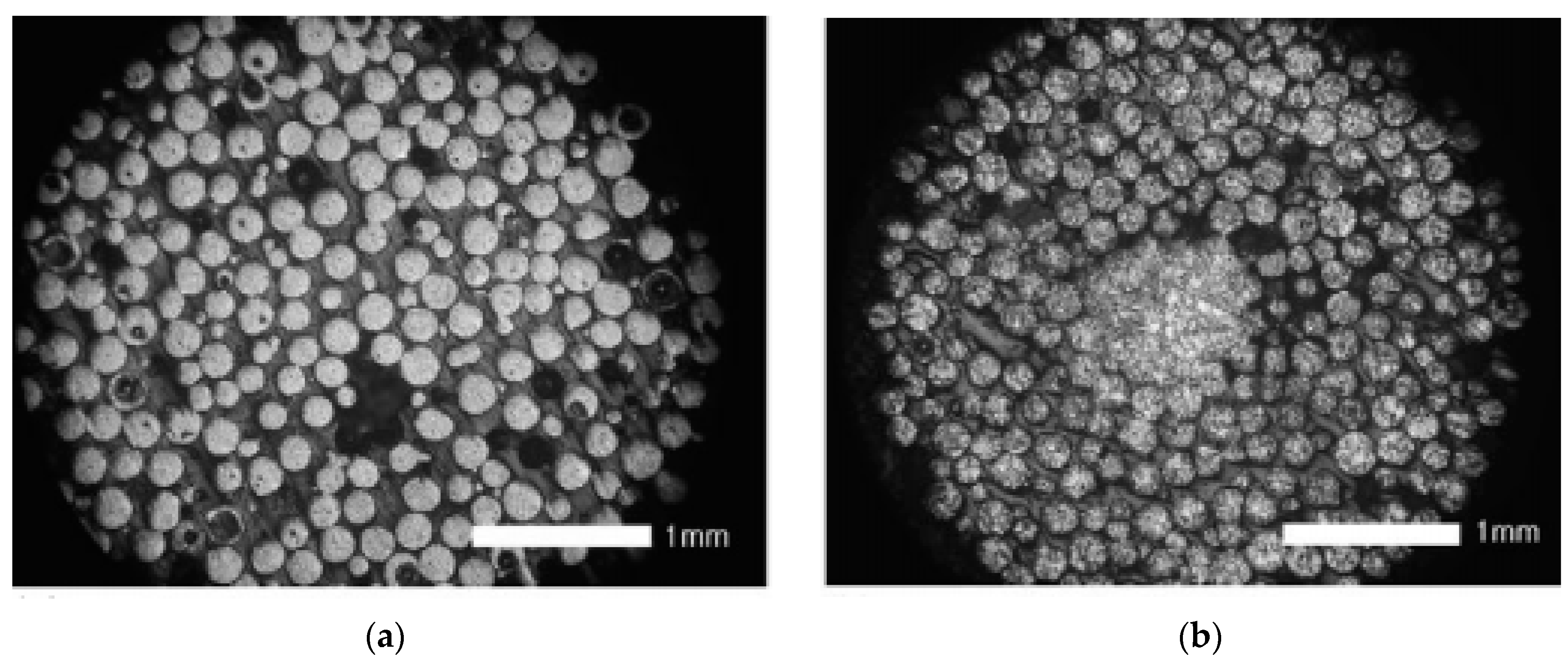
Figure 1. Effect of the pinch pressure under a low external applied pressure (7.8 MPa) on Ti powders: (a) powders joint at contact points with 1.07 kJ/g; (b) formation of a dense core with 1.43 kJ/g. Reprinted with permission from ref. [41], Copyright 2006 Elsevier.
Metals 11 00616 g001
Figure 2. Necks formation during electrical discharge consolidation (EDC) with 1.07 kJ/g and low external applied pressure (7.8 MPa) on Ti powders: (a) cross section of the compact; (b) detail of the necks formed. Reprinted with permission from ref. [48], Copyright 2017 Polska Akademia Nauk.
Metals 11 00616 g002
Figure 3. Finite elements method (FEM) simulation of the EDC process of a hollow cylindrical piece. Values of temperature, shrinkage and densification for different times during processing of Cu-diamond powders: (a) general overview; (b) detail of the zone near the powders. Reprinted with permission from ref. [52], Copyright 2015 John Wiley and Sons.
Metals 11 00616 g003
Figure 4. Evolution of the powder column electric resistance during EDC of metallic powders.
Metals 11 00616 g004
Figure 5. Effect of processing conditions on EDC: (a) similarly processed steel powders with different oxide thickness (from left to right, as received and annealed up to 60 min at 500 °C), reprinted with permission from ref. [62], Copyright 2009 Elsevier; (b) similar powders processed with 1.85 kV (top) and 5 kV (bottom), reprinted with permission from ref. [29], Copyright 2020 Taylor & Francis.
Metals 11 00616 g005
Figure 6. Configurations of the equipment used for EDC experiments: (a) direct discharge, reprinted from ref. [90]; (b) configuration for discharging after the use of a current transformer, reprinted with permission from ref. [43] Copyright 2010 Elsevier.
Metals 11 00616 g006
Figure 7. Typical current waveform for the cases of under-damped, critically-damped and over damped intensity functions in EDC process. Reprinted with permission from ref. [29] Copyright 2020 Taylor & Francis.
Metals 11 00616 g007
Figure 8. Comparison of the microstructure and the fracture surface of 1.2380/1.8905 mixture and pure 1.2380 steel, consolidated by capacitor discharge sintering (CDS) at 7500 µF and 24 V output voltage. Reprinted with permission from ref. [94] Copyright 2009 EPMA, ©Euro PM2009.
Metals 11 00616 g008
Figure 9. Scanning electron microscopy (SEM) images of EDC samples sintered with 300 MPa and 1.5 kJ/g showing the ferritic matrix and M6C carbides: (a) black arrows pointing to large and complex carbides (M6C with Fe, W, Cr, Mo and V) of 0.5–1.5 µm and white arrows pointing to residual pores; (b) extremely fine carbides (10–15 nm) homogenously dispersed in the ferritic matrix. Reprinted with permission from ref. [54] Copyright 2008 Elsevier.
Metals 11 00616 g009
Figure 10. Ferro-Titanit used in experiments: (a) chips obtained after machining the bulk materials; (b) microstructure of the chips consolidated by EDC. Reprinted with permission from ref. [104] Copyright 2014 John Wiley and Sons.
Metals 11 00616 g010
Figure 11. Consolidation of Al-12Si powders: (a) by EDC, with the original eutectic structure being maintained; (b) by spark plasma sintering (SPS), with the original microstructure being changed. Reprinted with permission from ref. [77] Copyright 2020 Elsevier.
Metals 11 00616 g011
Figure 12. Medical devices of porous titanium made by EDC: (a) dental implants; (b) vertebrae implant; (c) porous head endocardial electrode. Reprinted with permission from ref. [42] Copyright 2016 Elsevier.
Metals 11 00616 g012
Figure 13. SEM micrographs showing the consolidation of Al-Ti25 MA powders: (a) by EDS with 5 kJ/g, attaining a fine microstructure of bulk Ti3Al; (b) by conventional sintering at 1250 °C in a vacuum of 2 × 10⁻⁷ torr for 2.5 h, attaining a porous microstructure. Reprinted with permission from ref. [47] Copyright 2017 Polska Akademia Nauk.
Metals 11 00616 g013
Figure 14. Optical micrographs showing the consolidation of Ti-3TiC MA powders: (a) by EDS with 2.85 kJ/g, attaining crystallite sizes of about 40 and 54 nm for Ti and TiC, respectively; (b) by SPS, with TiC uniformly distributed only along the Ti particle boundary. Reprinted with permission from ref. [73] Copyright 2019 Elsevier.
Metals 11 00616 g014
Figure 15. EDC processing of amorphous Cu-based powders for different input energies: (a) XRD patterns; (b) DSC traces; and SEM micrographs of the compacts processed with (c) 0.44 kJ/g (0.2 kJ of total energy), (d) 0.66 kJ/g and (e) 1.11 kJ/g. Reprinted with permission from ref. [122] Copyright 2011 Elsevier.
Metals 11 00616 g015
Figure 16. SEM micrographs of WC-20Co material processed by EDC for input energies of: (a) 87 kA/cm2; (b) 95 kA/cm2. Reprinted from ref. [90]
Metals 11 00616 g016
Figure 17. Microstructure of the interface in nanocrystalline and coarse WC-10Co powders: (a) SEM image; (b) cobalt mapping showing a 15 µm thin layer with a higher cobalt content of about 14 wt.%. Reprinted with permission from ref. [125] Copyright 2008 Elsevier.
Metals 11 00616 g017
Figure 18. EDC processing of a graded Fe-W composite (0 to 75 vol.% W) joined to a V bulk disc: (a) sublayers with 0 and 25 vol.% W; (b) sublayer with 50 vol.% W; (c) sublayers with 50 and 75 vol.% W and V disc; and (d) magnification of the sublayer with 75 vol.% W and V disc. Reprinted with permission from ref. [88] Copyright 2019 Elsevier.
Metals 11 00616 g018
Figure 19. SEM micrographs of W compacts processed by EDC at (a) and (b) 1.5 kJ/g, and necks details for input energies of: (c) 1.5 kJ/g (total energy of 1.2 kJ), (d) 1.9 kJ/g and (e) 2.3 kJ/g. Reprinted with permission from ref. [123] Copyright 2012 Elsevier.
Metals 11 00616 g019
Figure 20. SEM micrographs of Nd-Fe-B compacts processed by EDC with different processing parameters. Details of fully compacted, insufficiently compacted and remelted zones are shown in detail. Reprinted with permission from ref. [128] Copyright 2018 Elsevier.
Metals 11 00616 g020
Table 1. Representative EDC processing parameters used by different researchers: mass M, capacitance C, voltage V, energy or specific energy E, current density J or peak intensity, and external pressure P. Values in italics are computed from other values in the table.
MaterialM, gC, μFV, kVE, kJ (kJ/g)J, kA/mm2 (kA)P, MPaDieRef.
Fe 79.8 3–120.36–5.750.23–0.980Pyrex, Ø 5.5–15 mm[36]
Fe 9.4 <75 (<7.98)1.56–2.34106–282Mullite, Ø 9 mm [28]
Fe 5.32–79.8 1.2–13.50.05–1.2 Pyrex[29]
Fe-1.5Mo 2 (1.3–3.4) 250Graphite, Ø 10 mm[105]
Fe-TiC 38400.0516–48 [104]
Steel 74.5 71.83 Ø 7.4 mm[102]
Steel (0.4–1.5) 50–300Graphite, Ø 10 mm[54]
Steel 5 1.5–4.4 0.75–2.85170–270Ø 10 mm[28]
Steel 1075000.024<40 (<4) Si3N4, Ø 16 mm[94]
Steel, Cu <79.8 12<5.750.16–0.58 Pyrex, Ø 7.6 mm [62]
Cu 2 (3.1) 300Ø 10 mm[121]
Cu-diam. 57201.24.12(68)125Øout 11, Øin 6 mm[52]
Cu-Zr-Ti-N; W 0.454500.7–1.5; 2.4–2.80.1–0.5 (0.22–1.11); 1.25–1.75 (2.8–3.9) 0Quartz, Ø 3–4 mm[123]
Ti0.73003.21.5 (2.14) 7.8Quartz, Ø 4 mm[55]
Ti0.7150–4503.20.75–2 (1.07–2.86)(13.5)7.8Quartz, Ø 4 mm[41]
Ti0.73002.61 (1.43) 7.8Quartz, Ø 4 mm[109]
Ti0.7150–4503.20.75–2 (1.07–2.86)149–276 (12–20.8)7.8Quartz, Ø 4 mm[37]
Ti; Sn; Zn1, 225,000, 2000.27–0.4, 10(0.9–2.04), (5) 70–710, 0Alumina, Ø 6.2 mm[26]
Ti; Nb; Ta <18001–5.90.9–31.3 0–30 [42]
Ti-6Al-4V 480–720 1.5–2.5 Ø 3.3 mm[110]
Ti-6Al-4V 4802.51.5 Ø 3.3 mm[61]
Ti-6Al-4V0.73002.61 (1.43) 7.8Quartz, Ø 4 mm[111]
Ti-6Al-4V0.7150–4501.8–5.20.75–2 (1.07–2.86)(17.5)7.8Quartz, Ø 4 mm[45,114]
Ti-6Al-4V0.7150–4501.8–5.20.75–2 (1.07–2.86)(21)7.8Pyrex, Ø 4 mm[38]
Ti-6Al-4V1240–720 (1–2.5) 0Pyrex, Ø 3.3 mm[72]
Ti-6Al-4V12402–4.6(0.5–2.5)(10.1–23.6)0Pyrex, Ø 3.3 mm[39]
Ti3Al0.34501.5–2.60.5–1.5 (1.67–5) 0Quartz, Ø 4 mm[47]
Ti5Si30.44505.58, 5.967, 8 (17.5, 20)(58.4, 60.8) Quartz, Ø 4 mm[115]
Ti5Si30.343004.1–5.82.5–5 (7.35–15.29)434–631 (33.6–48.8) Quartz, Ø 4 mm[40]
Ti-Zr-Ni0.454501.6–2.20.57–1.1 (1.27, 2.44) Quartz, Ø 4 mm[117]
Ti-TiC0.73003.16–4.08 1.5–2.5 (2.14–3.57) Quartz, Ø 4 mm[73]
Ni 42402.9–51–3 (0.25–0.75)4950 (12)0Pyrex, Ø 6 mm[35]
Ni-Ti (1.5–2.8) 155–360Ø 10 mm[118,119]
Al-12Si0.7906, 6.6, 7(2.31), (2.8), (3.15) 550Bakelite, Ø 8 mm[77]
Al alloy 25004–5.5(2–3.8) <450Ceramic 50 × 8 mm2[108]
Nb-Al7.35003.8–5.4(0.5–1) <450Alumina 50 × 8 mm2[129]
Nb-Al; Al alloy7; 510003.75–5.3; 5–6(1–2); (2.5–3.6) 500; 1170Ceramic, 50 × 8 mm2; Ø 8 mm[71]
Zr-1Nb 6000<6<1081.6–3.50–400Ø 13.7 mm[127]
WC-10Co2.53606.5(3) 300 [124]
WC-10Co 360 1.5–2.4300Ø 5.5 mm[125]
WC-20Co 6000<6<1080.75–1120–300Ceramic, Ø 10 mm[90]
WC-11Co; W-Ni-Fe13604.8–6(4.15–6.48)1.8–2.8300Ø 5.5 mm[50]
UN 2–3 160–210 [97]
Nd-Fe-B 10 40–72 (4–7.2) 176–388Si3N4, Ø 19 mm[128]
Publisher’s Note: MDPI stays neutral with regard to jurisdictional claims in published maps and institutional affiliations.