Abstract
The present contribution is the first research reporting full penetration HLAW joints in 15 mm thick EH36 steel butt T-welds with square grooves on 2F welding position by single-sided welding. The effects of welding parameters were investigated to increase the quality of the joints. Conditions leading to defect-free full penetration welds fulfilling naval regulations includes a laser power of 12.5 kW, a welding speed of 1.6 m/min and the vertical laser offset distance from the flange of 1 mm. Advanced characterization of selected welds included a microstructural identification by optical microscopy, SEM, and XRD, revealing the presence of acicular, polygonal and Widmanstätten ferrite, lath martensite, and some retained austenite at FZ. Hardness and microhardness mapping tests showed values of 155 HV at base metal and 200 to 380 HV at the fusion zone connecting the web to the flange.
1. Introduction
Hybrid Laser Arc Welding (HLAW) is an attractive joining method used as a single pass welding technique covering a wide range of thicknesses, with plates of up to 35 mm [1,2,3,4]. It provides good quality joints, minimal thermal distortions and improved productivity in comparison with conventional arc welding. HLAW uses high energy processes to ensure a great penetration depth and high welding speeds, which is achieved thanks to the combination of laser and electric arc welding processes [5,6].
In addition to the technical benefits of HLAW, numerous researches confirm that this technology provides a series of synergic effects and economic advantages that make it a profitable welding process for its implementation in many industrial fields demanding high quality welds of thick sheet metal parts, such as naval and offshore industries [7].
A remarkable advance for the application of HLAW in the offshore industry is exemplified in the work carried out by Üstündağ et al. [8], where 15 mm thick pipe segments were welded in 2G position using the defocusing of the laser beam technique. This new discovery avoided crater imperfections at the ends during the closure of the circumferential sleeves, demonstrating the industrial applicability of this welding process [8].
Hybrid technology is nowadays bypassing some traditional technologies in the manufacturing processes of 2D panels and 3D reinforced panels in shipbuilding. Cerwenka [9] reported the importance of the knowledge of materials, welding, and machining processes, equipment, and panel fabrication in butt and T-joints. Yoo et al. [10] mentioned that the allowed gap width is highly influenced by the morphology of the edges, the welding speed, the energy contribution per unit of length, and the welding process used. Therefore, to achieve high quality welded joints, the overall welding parameters have to be adapted to working conditions. Based on this, there is a need to have a system for automatic welding of fillet joints in the grillage assembling in ship structures, such as that designed by Yoo et al. [10]. Yoo et al. solved this using laser range sensors to guide a moving platform and a vision sensor to guide the manipulator’s end effector to the weld seam line by means of the development of a path planning algorithm and a control algorithm. On the other hand, Udin et al. proposed the use of an application to estimate the process parameters in complex welded constructions. This can be used for quick preliminary estimation of the result of HLAW welding [11].
Full penetration in butt T-joint HLAW is a demanding case for the shipbuilding industry, which is primarily supported by the driving force of distortion reduction. These local distortions are influenced by the welding procedure and the assembly sequence, affecting the final distortion of the whole structure [12]. This distortion in a stiffened panel is further exemplified in [13], using FEM simulation where several welding sequences are analyzed on a semi-industrial scale. The sequence leading to less distortion involved a variation of direction in the middle of the welding path on the reinforced panel, in addition to alternating trajectories between two following stiffeners.
Outstanding researches [14,15,16] also support the hypothesis that HLAW technology provides greater strength on T-joints compared to other naval joining technologies, such as hybrid plasma welding, friction welding, and explosive welding methods. For example, Guo et al. [14] show that hybrid plasma welding exhibits excellent all-round performance on aluminum alloys, especially high corrosion resistance, toughness, and weldability, widely used in shipbuilding and rail transportation, machinery manufacturing, and the chemical industry. Both hybrid plasma-MIG and HLAW processes combine the advantages of high energy density, deep penetration, good filling capacity, improving welding efficiency, and reducing welding defects.
HLAW is gradually progressing in the effectiveness of the joining between dissimilar materials, as demonstrated in [17] for the case of a steel to aluminium joint. One of the most consolidated technologies in shipbuilding for joining steel and aluminium is explosive cladded transition joining, in which coated materials are required to acquire high quality welds. Mechanical behaviour and fatigue life estimation of dissimilar explosive transition joints are studied by [15,18]. It should be reminded that knowing the fatigue behaviour of welded marine structures is of key importance, as they are subjected to variable loads over time due to waves and workloads of different amplitude values, provided that the most sensitive points of marine structures are the welded zones. Fatigue behaviour of marine structures welded with different technologies are studied in [19,20]. However, the literature regarding HLAW welded structures still misses a more in-depth study regarding the fatigue behaviour.
The evidence presented by fusion welding processes to easily weld high strength low alloy (HSLA) steels is widely demonstrated. Ragu Nathan et al. [16] carried out a comparative evaluation of the mechanical properties (tensile, impact, hardness) and microstructural characteristics of HSLA steel joints of shielded metal arc (SMA), gas metal arc (GMA), and friction stir welding (FSW). Fusion welding of these steels have been claimed to lead to problems such as cold cracking, residual stress, deformation and fatigue damage. Friction stir welding (FSW) seems to relieve some of these problems [16]. In this context, HLAW processes with a laser source seem to be a promising technology to join HSLA steels in shipbuilding [2,21].
The application of HLAW technology to T-joints is still limited, especially on thick plates. One of the most commonly adopted configurations for researchers to weld T-joints is a flat position (1F/PA) with 8 mm thickness [22,23,24]. These experiments showed sound full penetration welds when flange plates were at a fixed setting and an inclination angle with respect to the horizontal plane between 30° and 45°. For instance, the effectiveness to weld in the 1F position has been exemplified by Unt et al. [24], who focused their study on the effect of the initial sealing welding pass, run with defocused laser beam, on the quality of T-joint fillet welding. The quality of welds improves with this initial sealing welding pass, as the defects of the root side are minimized, such as irregular fusion and lack of penetration, but the production slows down. However, full penetration was not obtained in 10 mm thickness. Tsibulskiy et al. [25] followed a similar approach to weld T-joints by HLAW with 1F position but on thicker plates of 12.5 mm using a welding speed of 1.2 m/min. Angular welds and T-joints in one pass and in two passes, respectively, were carried out immediately after laser cutting without further edge preparation. Gaps between flange and web were fixed from 0.1 to 1 mm, working with an angle of incidence of the laser with respect to the flange of 5° [25]. This study revealed that a gap of 0.1 mm is optimal for welding T-joints. One of the problems presented by the 1F fillet welding position is that it is not reproducible at industrial scale within the shipyard since flat panels are formed in the 2F position.
It has also been reported by Bunaziv et al. [26] that the presence of a gap between welded plates increases the deep penetration in the root zone. This may be related to a more favorable melt flow, which allows the filler wire to be transported more effectively to the root because it requires less volume of base metal to be melted [26]. The authors indicate that the gap improves the entry of the laser beam into the joint and increases the multiple reflections within it, causing greater absorption of the beam and more efficient fusion. It should also be noted that an increase in the gap has a negative effect on the productivity, as higher materials need to be added at higher deposition rates, requiring lower welding rates to ensure the stable fusion of both base metal and filler wire. Thus, the wire feed rate must be increased when the gap is widened, taking care of keeping the welding process stable.
Limitations of laser power make double-sided welding more common, with single-sided welding usually being restricted to thinner welds. The key to apply double-sided welding is to ensure that the weld on the back side completely penetrates and melts the joint and the filler material deposited on the front side. In most cases, full penetration is guaranteed by sealing before welding the second side (rear welding). It is worth mentioning that the square grooves (straight edges) reduce the volume of filler material necessary to fill the rear face in butt T-joint welds if it is compared with beveled grooves. Several studied cases confirm the importance of edge preparation, which is also a key experimental parameter to be considered in the hybrid welding of T-joints. Both Bunaziv et al. [26] and Olschok [27] propose the realization of a small beveling on the edge of the stiffener (web), maintaining an opening angle with the flange, which boosts the entry of the laser beam to the root. Complex edge preparation (bevel groove), such as chamfering, improves the HLAW process efficiency, but would also slow down production. In fact, the machining of plates with straight edges simplifies and speeds up the takt time of the flat panel lines of the shipyards, making it a more feasible option.
Most structural T-joints require full penetration to fulfil the acceptance criteria of the evaluation rules and standards, as well as to ensure adequate performance. Table 1 shows a summary of the most employed shipbuilding standards. It includes the welding analysis methodology according to ISO 15614-14: 2013 standard [28] and the requirements entailed by Classification Societies, such as: Bureau Veritas [29], Lloyd’s Register [30] or Det Norske Veritas (DNVGL) [31], for the evaluation of T-joints EH36-TM material welded with the hybrid laser welding process.

Table 1.
Summary of standards and tests for the evaluation of HLAW T-joints according to shipbuilding regulation.
As indicated in Table 1, some discontinuities such as porosity, cracks, undercuts, or humps can be detected in macrographic tests of a representative section of the bead. Nevertheless, even though some imperfections may be found in macrographs, ISO 12932 standard [33] considers that different types of imperfections can be accepted if defects are below the established quality levels required for each weld. Three quality levels are classified to allow for the application of a wide range of welded manufacturing. They are designated by B, C, and D, where B level corresponds to the highest requirements.
The research presented here focuses on the shipbuilding assembling stage of joining stiffeners to horizontal flat panels, where the working area is long and narrow. Based on this industrial configuration, it is intended to reproduce the welding position PB (UNE-EN ISO 6947 [42]) or 2F (AWS A3.0. [43]), during the manufacture of reinforced flat panels, with the final objective of getting full penetration, guaranteeing the weld quality and achieving greater productivity.
As far as the authors are concerned, this is the first study reporting full penetration in 15 mm thick samples using straight edges without a gap in the PB/2F position. Likewise, the influence of the different parameters on the welding quality of T-joints has also been analyzed. Different processing parameters have been considered, such as the laser power, welding speed, heat input, and the vertical laser offset distance from the flange. To evaluate the welds quality, visual inspection, metallographic and microstructural analysis of cross-sections (by optical and electron microscopy), phases identification by X-ray diffraction, hardness measurements, and microhardness mapping tests were performed.
2. Materials and Methods
The material used was 15 mm thick EH36 thermomechanical naval steel plates, cut to 300 mm × 100 mm (length × width) pieces, with square grooves and grid blasted edges (Figure 1). Single-sided welding was performed using WDI 16 SG filler wire (according to AWS called ER70 S-6) with a diameter of 1.2 mm (WDI, Hamm, Germany). The chemical compositions of the base material (BM) and the filler wire were measured with an arc spark spectrometer, model OES-Spektrometer Spectrotest (Kleve, Germany). The results are shown in Table 2. Mechanical properties, provided by the manufacturer, of BM and the filler wire are included in Table 3.
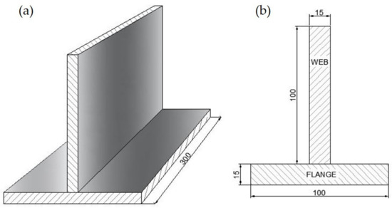
Figure 1.
Dimensions of the plates to be butt welded on T-joint: (a) overview, (b) side view, unit: mm.
Table 2.
Chemical compositions of base material and filler wire (wt %).
Table 3.
Mechanical properties of base metal and filler wire.
In the present research, samples were one side joined by HLAW in the T configuration with the aim of achieving full penetration in a single step. Figure 2 shows a general disposition of a sample during the welding test. In all welding experiments, the web was fixed to the flange by means of tack welds only on one side at each end of the welding path.
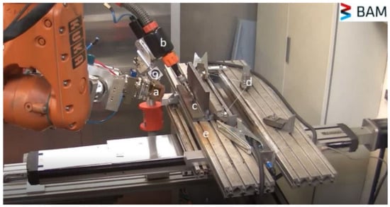
Figure 2.
General disposition of hybrid welding process: (a) laser head, (b) GMA torch, (c) workpieces, (d) clamps, and (e) working table.
All welding experiments were run on the 2F horizontal position using a 16 kW disk laser TruDisk 16002 (TRUMPF, Farmington, NM, USA) with a wavelength emission of 1030 nm and a beam parameter product of 8 mm × mrad. The laser source was used in conjunction with a Qineo Pulse 600 GMA (Gas Metal Arc) welder with a maximum current of 600 A (CLOOS, Haiger, Germany). Both power sources are integrated into a combined welding head that includes a laser beam transmitted by an optical fiber with a 200 μm diameter core and a GMAW torch. The scheme of the welding configuration is shown in Figure 3. The shielding gas used was a mixture of 18% CO2 in Argon at 20 L min−1, which flowed directly through the GMAW torch.
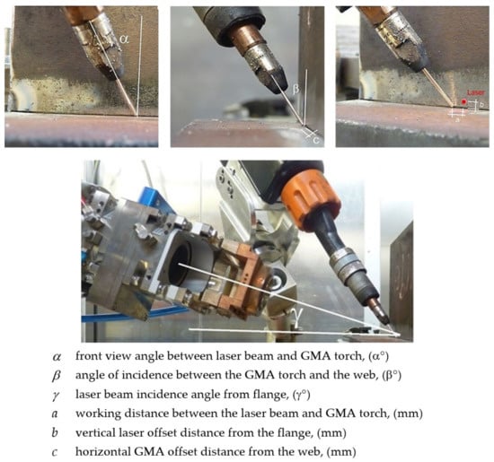
Figure 3.
Geometric configuration of the laser and GMA sources to workpiece.
A series of six single-pass welding tests were carried out in laser leading configuration. The welding parameters used for this investigation are given in Table 4. The axis of the laser source (γ) was tilted at an angle of 6°, with respect to the surface of the flange. The arc welding torch (β) was tilted at an angle of 31°, with respect to the surface of the web, and the torch kept a travel angle (α) of 26° to the welding direction, which is orthogonal to the normal of both planes (web and flange). The distance from the laser focus to the arc torch was 3.5 mm. The focal point position was set at a value of −5 mm. The wire feed rate remained constant at a value of 13 m/min, as well as the stick-out wire whose value was set at 16 mm and the GMA displacement away from the joint (c) also remained constant in all tests without any distance (0 mm). Besides, the arc mode was pulsed for all welding experiments. All these fixed parameters were experimentally fitted according to previous experience of the authors and some preliminary welding tests.
Table 4.
Welding variables and parameters of hybrid head for T-joints on single sided.
Welded samples were tested following the guidelines referenced in ISO 15614-14: 2013 standard [28]. These tests include visual inspection, metallographic evaluation of cross-sections, microhardness mapping by means of the UCI (Ultrasonic Contact Impedance) Hardness Scanner device, model UT200 (BAQ, Braunschweig, Germany), and experimental HV10 hardness measurements performed with a CENTAUR Hardness tester, model RB2-200DA (CENTAUR, London, UK) following the ISO 9015-1: 2011 standard [41] as a guideline.
Cross-sections of single-sided welds were analyzed to study the shape of the welds. They were cut halfway through the weld and were subsequently prepared according to the standard procedures of grinding, sanding, and polishing. Polished samples were etched using a 2% Nital HNO3 solution to reveal the microstructure, shape, and size of the beads, and the weld quality. These cross-sections were deeply analyzed with an optical microscope.
Despite the high complexity of the hybrid process, its remarkable characteristics not only affect geometric and mechanical matters, but also metallurgical properties. After metallographic preparation, the geometric profiles of the specimens were evaluated, evidencing the possible presence of imperfections considered by ISO 12932 [33] for hybrid laser-arc welding of steels.
In order to analyze the effect of hybridization on the best results of one pass welds, microhardness maps were generated. Additionally, the microstructure in all regions of selected welds was examined using the Perfect Image V8.01 software of the optics microscope. This study allowed for the correlation of metallurgical transformations undergoing the dissimilar thermal cycles during the HLAW process. Likewise, the penetration/width ratio of the weld beads, and the magnitude of the found defects were measured.
Further investigation was developed to observe the microstructure of the T-joint in the laser zone, arc zone, and base metal. The detailed analysis of the microstructural characteristics in the different areas was carried out using a FEI (Thermo Fisher, Hillsboro, Oregon, USA) Nova NanoSEM 450 Scanning Electron Microscope (SEM) coupled to an Energy Dispersive Spectrum (EDS) detector. Both optical and electron microscopy studies allowed the analyses of the depth-width relationship and the microstructure of the laser and arc fusion zones.
Energy dispersive X-ray fluorescence (XRF) spectroscopy was used to analyze the type and content of the elements of different HLAW weld zones. Thus, welds were locally irradiated at the base metal, the root laser fusion zone, and the throat arc fusion zone. These 2D area scans (element mapping) measurements were taken with a Bruker (Bruker Optics Inc, Billerica, Massachusetts, USA) M4 Tornado spectrometer (50 kV, 600 μA), using a vacuum of 19 mBar.
Different sections of the HLAW welds were extracted to be analyzed by X-ray diffraction (XRD). Thus, representative samples of base metal, root laser fusion zone and throat arc fusion zone were cut and studied by XRD to identify phases, using a Bruker (Bruker Optics Inc, Billerica, Massachusetts, USA) instrument, model D8 ADVANCE A25, with LYNXEYE detector (silicon strip detectors). The diffractograms were recorded under the following conditions: CuKα radiation, scan range from 2θ = 10° up to 120°, with a step size of 0.04° and a time per step of 1 s.
3. Results and Discussion
3.1. Effect of Process Parameters
Figure 4 reports macrographic images of the HLAW welds encoded as A–F in Table 4. Cross-sections of the weld beads of samples A–F have been included in Figure 5. All macrographs had a typical high aspect ratio configuration with a greater volume of weld metal on the face side of the T-joint (arc-zone) compared to the root side (laser-zone). This first part of the research carried out on single-sided T-joint welding analyses the influence of some experimental variables, such as laser power, welding speed, heat input, and the laser beam offset “b”.
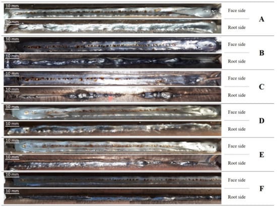
Figure 4.
Top view macrographic images of face and root sides at A–F weld beads, as indicated in Table 4.
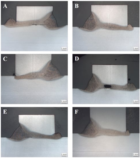
Figure 5.
Cross-sections of one side HLAW T-joints welded under conditions (A–F), as indicated in Table 4.
As shown in Table 4, the laser power selected for the initial welding test A was 14.5 kW, which generated a profound input energy. The most likely consequence of this high laser power was the displacement of a considerable amount of molten material driven towards the root. Additionally, other imperfections appeared in this A sample, such as: lack of fusion, asymmetric shape of the root with a higher percentage of material attached to the flange, as well as slight undercuts both in the connection with the flange as with the web. Based on experiment A, it was decided to reduce the power to a value of 12.5 kW. It should be mentioned that the metal volume coming out from the weld root was reduced when less laser power was used. This effect also decreased as the welding speed increased. Bunaziv et al. [26] conducted a similar welding study on one side the HLAW butt T-joints in 15 mm thickness with 10 kW, keeping the flange at a vertical position but without reporting full penetration.
Lack of fusion was detected in A, C, D, and E specimens. This defect was in the central area of A, D, and E joints. In specimen C, the lack of fusion appeared at the root due to low laser beam offset.
The evidence of an empty cavity inside the joint can be clearly seen in specimen D. The finding indicates the collapse of the keyhole. The cavity formation observed in sample D is avoided in sample E, most likely because of the higher welding speed used in this latter weld, leading to a reduced supplied energy. Provided the positive influence of increasing the welding speed up to 1.6 m/min, this variable was kept in F condition. This welding speed was slightly higher than that used in [26] (1.5 m/min).
An important experimental variable in this welding configuration is the offset of the laser beam. The laser offset varied between the values of 0.7 mm (sample C), 1 mm (sample B), and 1.3 mm (sample D), showing the best results with a value of 1 mm, which produced the complete fusion of the joint. As expected, a change in “b” (vertical laser offset distance from the flange) drastically affects the results. The best vertical laser beam offset distance from the flange of 1 mm was kept for sample F, which was generated with a lower heat input with respect to the other samples (as the welding speed was higher). Therefore, it can be concluded from the overall results that welds with “b” equal to 1 mm provided the best output (samples B and F), in which the electric arc is hardly altered and tends to be more stable. Sample F presented better results than sample B for the higher welding speed, avoiding the bulge effect observed in the center of this latter sample, which led to the crack formation.
According to previously discussed results, some welds suffered from some relevant defects; welds A, C, D, and E showed lack of fusion, while seams B and C presented humps, as in [44]. Thus, as condition F presented better results than the other welds, A-–E, weld F was subsequently analyzed in detail. This advanced study focused on the verification of quality results, on the deep analysis of the microstructure by optical and electron (SEM/EDS) microscopy, on phases identification by X-ray diffraction, and on the hardness measurements.
3.2. Quality Verification and Deep Analysis of Best Weld (F)
Standard UNE-EN ISO 12932:2013 [33] has been followed in the present paper to verify the quality of specimen F. Table 1 indicates the tests required by this standard.
3.2.1. Evaluation of Imperfections
An exhaustive macrographic analysis was carried out on specimen F to evaluate the quality level of defects (Figure 5F), not finding relevant internal imperfections or those related to the geometry of this T-joint, such as misalignment or imperfect root. The depth-width aspect ratios of the laser zone and arc zone at specimen F were 9.4 and 0.7, respectively. The average penetration of the laser zone was more than two times larger than that of the arc zone. The average width of the laser zone was 1/6 of the average of the arc zone.
From a superficial visual inspection, no cracks, pores, or lack of fusion were appreciated. A very slight undercut was observed throughout the toe, which connected with the flange. The undercut depth was measured to be 0.13 mm, a value significantly lower than 0.5 mm, the maximum limit required for quality level B for this thickness, according to ISO 12932:2013 [33]. A gradual transition of the seam between the flange and the web was produced without revealing over convexity. The excess penetration appreciated in the root was measured, verifying that its value is below the limits established for quality level B. The lengths of the weld toes are also within the limits of this type of imperfection for quality level B, without presenting excess asymmetry in the throat of the T weld. Besides, no projections or spatters were originated on the surface of the plates. Therefore, conformity in the imperfection assessment seems to predict a good weld quality. Similarly, a quality level B according to ISO 12932 [33] in the evaluation of internal and external defects was obtained by Tsibulskiy [25] on one side HLAW T-joints with 12.5 mm thickness welded on the flat position 1F. The experimental tests reported in [4] allowed authors to obtain weld seams on 14 mm T-joints from steel E36 using 14.5 kW laser power. Unfortunately, authors did not provide key experimental parameters to reproduce the welds, such as welding position, head angles, or edge preparation.
To ensure that the internal imperfections are not relevant and fulfil the standard requirements, the complete section was analyzed in detail with the optical microscope and SEM. An isolated pore in the laser fusion zone was found (Figure 6). The pore diameter (0.069 mm) was much lower than the limits of an isolated pore for B quality level (0.819 mm) established in the standard UNE-EN ISO 12932: 2013 [33]. Additionally, weld F does not present the solid inclusions of oxide, slag, flux, or copper. Very low porosity formation is also reported in the work of Üstündağ et al. [45]. In order to prevent porosity, Üstündağ et al. ascertain that using an oscillating magnetic and electric field (EMF) and its influence on the welding depth favor the stability of the keyhole on a butt configuration of a 25 mm thick structural steel plate (S355J2).
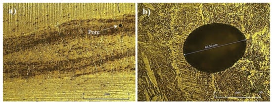
Figure 6.
Pore observed at laser fusion zone: (a) 50× magnification (b) 1000× magnification.
3.2.2. Microstructural Analysis at Fusion Zone
Figure 7 shows optical metallographic images of cross-sections of sample F. Figure 7a, taken at 20×, depicts the full view of this weld, in which the arc fusion zone has been highlighted in yellow and the laser fusion zone in blue. Figure 7b–d, obtained at 1000×, show the representative microstructure of the base metal, GMA fusion zone and laser fusion zone, respectively. The base metal (Figure 7b) is characterized by thin layers of pearlite which were distributed with thicker ferrite layers. These bands in the microstructure result from the thermomechanical controlled rolling process, which involves the strict control of both the temperature and the rolling reduction. Images c and d of Figure 7 show that both arc and laser fusion zones presented a similar microstructural pattern, with needle-shaped acicular ferrite, appearing with light tones, and some dark small spherical particles that can be due to a chemical attack. The acicular ferrite microstructure has also been previously identified in [46] at HLAW fusion zone of DH 36 naval steel. In addition to acicular ferrite, the microstructure of GMA FZ (Figure 7c) presents polygonal and Widmanstätten ferrite. Detailed analysis revealed evidence of lath martensite formation and some retained austenite. Martensite phase has been previously identified by Wei Liu et al. [23] in fusion zone of 8 mm HLAW T-joints of AHSS steel. Additionally, bainitic microconstituents can also be present, provided that the filler wire used (ER70 S-6) can promote bainite formation in HLAW [23,47,48]. The mixture of all these microconstituents is also reported in [49].
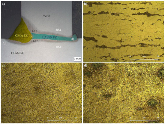
Figure 7.
Optical metallographic images of cross-sections of the HLAW F sample (a) image at 20× with fusion zones highlighted (arc in yellow and laser in blue); (b) image of base metal at 1000×; (c) image of GMA fusion zone at 1000×; (d) image of laser fusion zone at 1000×.
Laser FZ (Figure 7d) reveals similar microstructure than GMA FZ, although presenting a finer microstructure due to the higher cooling rate. This can lead to a higher percentage of lath martensite, and a reduced amount of ferrite and bainite based microconstituents.
It should be considered that the GMA fusion zone is affected by both laser and arc heat sources, while the laser zone is generated mainly by the laser heat source. In the arc zone of specimen F, the higher heat input (total hybrid heat input = 805.28 J/mm) leads to a relatively wide and large fusion zone. In contrast, the laser zone is much narrower (as shown in the aspect ratio), due to the highly focused laser source (laser heat input = 468.75 J/mm). Therefore, the arc region (Figure 7c) undertakes a slower cooling rate, and consequently, leads to softer microstructural components. The laser fusion zone (Figure 7d) displays a finer microstructure than the GMA fusion zone (Figure 7c), surely related to the higher cooling rate at the root of the weld compared to the face side. In regard to the microstructural constituents of the Laser FZ (Figure 7d), more lath martensite content than in GMA FZ was observed. Similar results are reported by [50] where the total hybrid heat input in the FZ cross-section was 775 J/mm [51].
It can be reminded that the microstructure of the fusion zone depends on how quickly the solidification takes place from the austenitic phase region. As the cooling rate is relatively fast in a HLAW process, ferrite side-plates protrude from the proeutectoid ferrite and project into the austenite grains. These side-plates, called Widmanstätten ferrite plates, have a wedge like shape, and their broad faces comprise flat areas separated by ledges. The growth process involves the nucleation and sideways migration of the ledges that separate the flats [52]. Considering this and the deep analysis of images (c) and (d) of Figure 7, Widmanstätten ferrite plates and lath martensite can be identified in both weld zones.
The thickness of these microstructure ledges is related to the cooling rate. Thus, the laser zone presented a lower ledge thickness than the arc zone, as a consequence of the higher cooling rate. The average ledges thickness (distance between flats) have been studied by SEM. Analysis and measurement of the microstructure by SEM confirmed a greater microstructure refinement in the laser zone, as shown in Figure 8a,b. The distances between plates have been measured in both laser and GMA fusion zones, being the average distance between plates of 1.114 μm at the arc zone (Figure 8a) and 0.595 μm at the laser zone (Figure 8b).
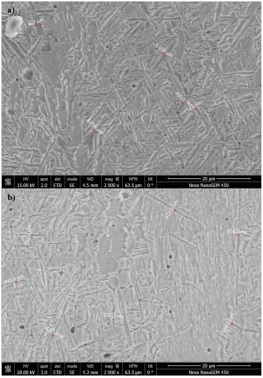
Figure 8.
SEM images of both fusion zones with measurements of microstructure ledges thickness: (a) GMA FZ and (b) laser FZ.
EDS were carried out in representative areas of the weld to analyze the chemical composition. No significant changes in the composition were detected neither at the laser nor at the arc fusion zones (Figure 9). Thus, the formation of carbides or intermetallic compounds containing alloying elements of base metal and filler (such as Carbon, Silicon and Manganese) could not be detected. These results are not surprising because of the low concentration of alloying elements in the base metal and filler wire. In any case, as widely known, the EDS technique is not especially sensitive to the quantitative detection of low atomic weight elements, such as carbon.
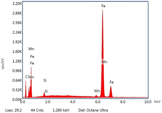
Figure 9.
Representative EDS spectra at the laser zone.
X-ray fluorescence analysis was undertaken to determine the chemical composition of the different areas of the welded samples. Figure 10 shows the different areas analyzed by XRF: base metal, Laser FZ (root), and GMA FZ (throat). Results are provided in Table 5. The chemical composition of FZs did not differ much from the base metal zone. Alloying elements and % weight of detected elements were in good agreement with the initial characterization analysis of EH36 steel and filler wire listed in Table 1. Only a slight increase in silicon (and manganese at a lower extent) coming from the filler wire stood out in the throat GMA FZ.
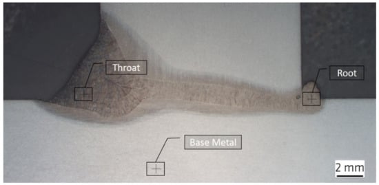
Figure 10.
Interest areas of the welded sample where X-ray fluorescence analysis took place.
Table 5.
Chemical composition measured as weight percent (weight %) by X-ray fluorescence analysis.
Figure 11 presents the X-ray diffractograms of base metal (BM), root laser fusion zone (Laser FZ), and throat arc fusion zone (GMA FZ). The figure includes the peaks assignation to present phases and the planes providing each peak. Three main phases are clearly identified: Ferrite (α), Martensite (M), and Retained Austenite (γ). As the cementite fraction is very low at this steel, BM only presented peaks associated to the ferrite phase, at the following 2θ angles: 44.7°, related to α plane (110); 65.0°, related to α (200); 82.3°, related to α (211); 98.9°, related to α (220); and 116.3°, related to α (310). Diffractograms of GMA and Laser FZ presented peaks associated to Ferrite (α), Martensite (M) and Retained Austenite (γ). The peak appearing at 2θ = 44.5° of both FZs is mainly due to α (110), although martensite also provided signals at this angle: M (101) and M (110). In GMA and the Laser FZ samples, the peaks at 2θ = 65.0°, 82.3°, and 98.9° are less intense than in base metal, revealing that ferrite is still present at the fusion zones, but at a lower percentage than in base metal. Both FZ samples presented clear martensite peaks at 2θ = 80.8° (112) and 97.5° M (202), and retained a austenite peak at 2θ = 76° (220) [53]. Laser FZ provides slightly higher martensite peaks and lower ferrite peaks than the GMA zone, indicating that the laser zone presents a higher martensite percentage than the GMA zone. This result is expected, due to the higher cooling rate of the laser FZ.
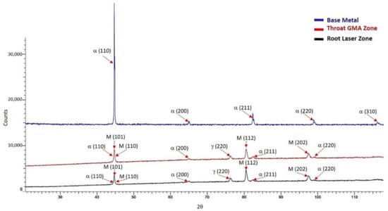
Figure 11.
X-ray diffractograms, including phases identification, of base metal, root laser fusion zone, and throat arc fusion zone.
3.2.3. Hardness
A microhardness map results of specimen F is illustrated in Figure 12a where a different color scheme is used. The redder regions are the zones of greater hardness; the gradual decrease in overall hardness is obvious as the color changes on the scale to blue in base metal. Figure 12b shows experimental HV10 hardness results obtained for the same sample.
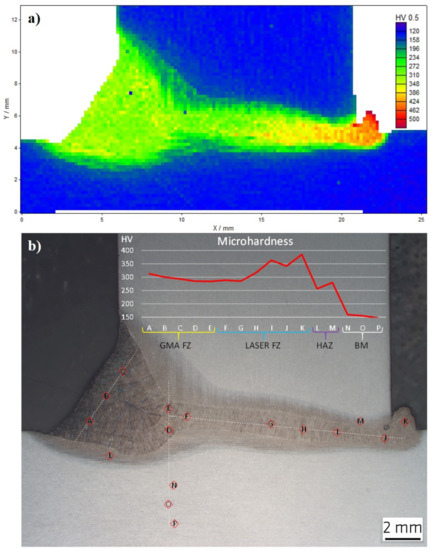
Figure 12.
(a) Microhardness map of the F specimen on one side weld; (b) hardness variations within the T-joint hybrid weld sample.
The base metal presents the lowest hardness values, around 155 HV. These results are related to the soft ferritic and perlitic microstructure previously discussed. The connecting fusion zone between web and flange show harder values, between 200 and 380 HV. The average hardness of the weld metal showed a slight increase when passing from the arc zone towards the laser zone, as in [54]. The slightly higher hardness of the laser zone, in comparison with the arc zone, is related to the higher martensite formation and the lower distance between the plates in the developed lathy microstructure. This microstructural change is generated due to the slower cooling rate of arc zone during the solidification process. In general, the intermediate hardness values of macro-section F represented in Figure 12a in green and yellow fulfil the maximum hardness required by standards (380 HV, according to UNE-EN ISO 9015-1 [41]). Note that, although higher hardness values were measured at the protruding melt of the root, this leftover zone is not relevant, as it is usually removed after welding. The overall obtained hardness values are due to the martensite formation at the fusion zone, with a higher extent in the root zone. To conclude, the hardness measurements of 15 mm thick EH36 steel single-sided hybrid T-joint weld presented values within the limits of the applicable regulation.
The experimental approach that was followed allowed us to obtain full penetration in sample F and welding on single sided by means of adjusting process variables. Resultingly, sample F presented acceptable quality for shipbuilding using the HLAW process on 15 mm thick T-joints plates of EH36-TM material.
This study reveals the need for further research on panels of larger dimensions than those of the laboratory, where the fatigue behavior and resistance of the structure can be studied on a semi-industrial scale.
4. Conclusions
The present study developed the HLAW process to perform single sided butt T-joints on 15 mm thickness EH36-TM plates welded in the 2F position. The influence of some HLAW parameters such as laser power, welding speed, and the vertical laser offset distance from the flange was analyzed. The adjusted combination of welding variables allowed authors to obtain high quality full penetration joints.
To avoid the appearance of welding imperfections such as lack of fusion (sometimes leading to an empty cavity formation inside the joint), asymmetric weld shape, and slight undercuts, appropriate HLAW experimental variables were carefully fitted. Conditions avoiding these defects involve a laser power of 12.5 kW, a welding speed of 1.6 m/min and the vertical laser offset distance from the flange of 1 mm. The weld performed under these conditions (F specimen) was analyzed in detail, by means of advance studies including quality verification, deep analysis of microstructure by optical and electron microscopy, phases identification by X-ray diffraction, chemical analyses by EDS and XRD, and hardness measurements.
The evaluation of the internal imperfections carried out on the selected specimen (F) agreed with the most restrictive quality level (B level), according to ISO 12932 [33]. The microstructure analyzed at FZ mainly consisted of a mixture of different ferrite morphologies (acicular, polygonal and Widmanstätten), bainite, lath martensite, and some retained austenite. X-ray diffraction confirmed the presence of the ferrite, martensite, and austenite phases. Optical and SEM studies (together with X-ray diffraction) revealed a greater refinement in the laser zone, compared to the arc zone. This finding is related to the higher cooling rate of the laser zone, leading to a higher percentage of lath martensite, and reduced amount of ferrite and bainite based microconstituents. A deep analysis of the optical and SEM images have allowed the identification of Widmanstätten ferrite plates and lath martensite in both weld zones. The thickness of these microstructure ledges (average distance measured between ledges) was related to the cooling rate. The thickness at arc zone was 1.114 μm and 0.595 μm at the laser zone. EDS studies did not detect significant chemical composition changes between laser and arc fusion zones. X-ray fluorescence analyses of different weld zones indicated a similar chemical composition to EH36 steel and filler wire. Only a slight increase in silicon (and manganese at a lower extent) coming from the filler wire stands out in the throat GMA FZ.
Microhardness mapping performed by Ultrasonic Contact Impedance and experimental hardness values confirmed the microstructure developed at different zones. Base metal presents the lowest hardness values, around 155 HV, while the fusion zone connecting web to flange show harder values, between 200 and 380 HV. Admissible hardness values according to the applicable regulations of the naval sector were obtained within the fusion zone connecting the web to the flange.
The present contribution is the first research reporting full penetration in single sided butt T-joints HLAW process in 15 mm thick steel samples using straight edges without gap in PB/2F position.
5. Future Research
The present study reveals that the HLAW process can be successfully employed to obtain high quality T-joints of 15 mm thick steel samples using industrial configuration (straight edges without gap in PB/2F position). Future research should focus on:
- -
- Application of this technology to weld panels of larger dimensions than those of the laboratory, including both semi-industrial (1–2 m long welds) and industrial scales (10–20 m long welds). The analyses of welding distortion and residual stresses of these industrial T-joints are of great interest.
- -
- Analyses of the fatigue behavior and resistance of the structure on a semi-industrial scale. These mechanical studies are missing at the reported literature. The lack of knowledge regarding fatigue behavior of HLAW joints is especially relevant.
Author Contributions
Methodology and validation, C.C.; investigation, C.C., A.G.; conceptualization, J.M.S.-A., A.G. and M.R.; data curation, C.C. and J.M.S.-A.; visualization, C.C.; resources and funding acquisition, M.P.-L., A.G. and M.R.; supervision, J.M.S.-A., A.G. and M.R.; project administration, J.M.S.-A., A.G. and M.R.; writing—original draft, C.C. and J.M.S.-A.; writing—review and editing, C.C., J.M.S.-A., A.G. and M.R. All authors have read and agreed to the published version of the manuscript.
Funding
The present paper belongs to C. Churiaque’s PhD. She would like to thank to the Vicerrectorado de Política Científica y Económica of the University of Cádiz and Navantia S.A. S.M.E. for the financial support of her industrial doctoral thesis (grant reference TDI-2-18). In addition, the fellowship covering her stay in Division 9.3 of BAM is acknowledged to the Campus of Global International Excellence of the Sea CEI • MAR.
Acknowledgments
C. Churiaque would like to thank to BAM for providing facilities and technical support (specially to Ömer Üstündağ and Marco Lammers) to conduct the experiments included in the present contribution.
Conflicts of Interest
The authors declare no conflict of interest.
References
- Egerland, S.; Staufer, H.; Ruehrnoessl, M.; Schorn, M. Investigation of advanced laser-MAG tandem hybrid welding for joining gap-flawed thin sheet metal parts. Weld. World 2018, 62, 95–104. [Google Scholar] [CrossRef]
- Üstündaǧ, O.; Gook, S.; Gumenyuk, A.; Rethmeier, M. Mechanical properties of single-pass hybrid laser arc welded 25 mm thick-walled structures made of fine-grained structural steel. Procedia Manuf. 2019, 36, 112–120. [Google Scholar] [CrossRef]
- Ustündag, O.; Avilov, V.; Gumenyuk, A.; Rethmeier, M. Full penetration hybrid laser arc welding of up to 28 mm thick S355 plates using electromagnetic weld pool support. J. Phys. 2018, 1109, 12015. [Google Scholar] [CrossRef]
- Turichin, G.; Kuznetwov, M.; Tsibulskiy, I.; Firsova, A. Hybrid Laser-Arc Welding of the High-Strength Shipbuilding Steels: Equipment and Technology. Phys. Procedia 2017, 89, 156–163. [Google Scholar] [CrossRef]
- Churiaque, C.; Chludzinski, M.; Porrua-Lara, M.; Dominguez-Abecia, A.; Abad-Fraga, F.; Sánchez-Amaya, J.M. Laser Hybrid Butt Welding of Large Thickness Naval Steel. Metals 2019, 9, 100. [Google Scholar] [CrossRef]
- Churiaque, C.; Chludzinski, M.; Dos Santos, R.E.; Sánchez-Amaya, J.M.; Porrua-Lara, M.; Abad-Fraga, F. Laser hybrid welding in shipbuilding. In Proceedings of the RINA (Royal Institution of Naval Architects) International Conference Marine Design, Cádiz, Spain, 15–16 January 2020; pp. 65–73. [Google Scholar]
- Gao, M.; Zeng, X.Y.; Hu, Q.W. Effects of welding parameters on melting energy of CO2 laser-GMA hybrid welding. Sci. Technol. Weld. Join. 2006, 11, 517–522. [Google Scholar] [CrossRef]
- Üstündağ, Ö.; Gook, S.; Gumenyuk, A.; Rethmeier, M. Hybrid laser arc welding of thick high-strength pipeline steels of grade X120 with adapted heat input. J. Mater. Process. Technol. 2020, 275, 116358. [Google Scholar] [CrossRef]
- Cerwenka, G.; Steinmeier, O.; Petronis, E.; Keßler, T.; Fisher, H.W.A.; Fiedler, W.; Schulze, F.; Emmelmann, C. Development of a flexible low laser power hybrid (LLPH) technology for shipbuilding including additive manufactured semi-automated hand-held unit. Procedia CIRP 2018, 74, 770–774. [Google Scholar] [CrossRef]
- Yoo, W.-S.; Kim, J.-D.; Na, S.-J. Study of a mobile platform-manipulator welding system for horizontal fillet joints. Mechatronics 2001, 11, 853–868. [Google Scholar] [CrossRef]
- Udin, I.N.; Voropaev, A.A.; Unt, A. Application Development for the Evaluation of Penetration in Laser and Laser-Arc Hybrid Welding of Tee and Corner Joints. Key Eng. Mater. 2019, 822, 381–388. [Google Scholar] [CrossRef]
- Deng, D.; Murakawa, H.; Ma, N. Predicting welding deformation in thin plate panel structure by means of inherent strain and interface element. Sci. Technol. Weld. Join. 2012, 17, 13–21. [Google Scholar] [CrossRef]
- Hammad, A.; Churiaque, C.; Sánchez-Amaya, J.M.; Abdel-Nasser, Y. Experimental and numerical investigation of hybrid laser arc welding process and the influence of welding sequence on the manufacture of stiffened flat panels. J. Manuf. Process. 2021, 61, 527–538. [Google Scholar] [CrossRef]
- Guo, Y.; Pan, H.; Ren, L.; Quan, G. An investigation on plasma-MIG hybrid welding of 5083 aluminum alloy. Int. J. Adv. Manuf. Technol. 2018, 98, 1433–1440. [Google Scholar] [CrossRef]
- Böhm, M.; Kowalski, M. Fatigue life estimation of explosive cladded transition joints with the use of the spectral method for the case of a random sea state. Mar. Struct. 2020, 71, 102739. [Google Scholar] [CrossRef]
- Ragu Nathan, S.; Balasubramanian, V.; Malarvizhi, S.; Rao, A.G. Effect of welding processes on mechanical and microstructural characteristics of high strength low alloy naval grade steel joints. Def. Technol. 2015, 11, 308–317. [Google Scholar] [CrossRef]
- Mazar Atabaki, J.; Ma, W.; Kovacevic, L.R. Hybrid laser/arc welding of advanced high strength steel to aluminum alloy by using structural transition insert. Mat. Des. 2015, 75, 120–135. [Google Scholar] [CrossRef]
- Kowalski, M. Identification of fatigue and mechanical characteristics of explosively welded steel—Titanium composite. Frattura ed Integrità Strutturale 2017, 11, 85–92. [Google Scholar] [CrossRef]
- Erny, C.; Thevenet, D.; Cognard, J.-Y.; Korner, M. Fatigue life prediction of welded ship details. Mar. Struct. 2012, 251, 13–32. [Google Scholar] [CrossRef]
- Xing, S.; Dong, P.; Threstha, A. Analysis of fatigue failure mode transition in load-carrying fillet-welded connections. Mar. Struct. 2016, 46, 102–126. [Google Scholar] [CrossRef]
- Üstündaǧ, O.; Avilov, V.; Gumenyuk, A.; Rethmeier, M. Improvement of Filler Wire Dilution Using External Oscillating Magnetic Field at Full Penetration Hybrid Laser-Arc Welding of Thick Materials. Metals 2019, 9, 594. [Google Scholar] [CrossRef]
- Mazar Atabaki, M.; Yazdian, N.; Kovacevic, R. Hybrid laser/arc welding of thick high-strength steel in different configurations. Adv. Manuf. 2018, 6, 176–188. [Google Scholar] [CrossRef]
- Liu, W.; Ma, J.; Yang, G.; Kovacevic, R. Hybrid laser-arc welding of advanced high-strength steel. J. Mater. Process. Technol. 2014, 214, 2823–2833. [Google Scholar] [CrossRef]
- Unt, A.; Lappalainen, E.; Salminen, A. Autogeneous laser and hybrid laser arc welding of T-joint low alloy steel with fiber laser systems. Phys. Procedia 2013, 41, 140–143. [Google Scholar] [CrossRef][Green Version]
- Tsibulskiy, I.A.; Akhmetov, A.D.; Korsmik, R.S.; Voropaev, A.A.; Mendagaliyev, R.V.; Eremeev, A.D. The influence of the gap size on the formation of a welded joint in hybrid laser-arc welding of angular joints and T-joints. J. Phys. Conf. Ser. 2018, 1109, 12033. [Google Scholar] [CrossRef]
- Bunaziv, I.; Dørum, C.; Ren, X.; Eriksson, M.; Akselsen, O.M. Application of LBW and LAHW for fillet welds of 12 and 15 mm structural steel. Procedia Manuf. 2019, 36, 121–130. [Google Scholar] [CrossRef]
- Olschok, S. Laserstrahl-Lichtbogen Hybridschweißen von Stahl im Dickblechbereich; Shaker Verlag: Aachen, Germany, 2008. [Google Scholar]
- UNE-EN ISO 15614-14. Specification and Qualification of Welding Procedures for Metallic Materials—Welding Procedure Test—Part 14: Laser-Arc Hybrid Welding of Steels, Nickel and Nickel Alloys; ISO: Geneva, Switzerland, 2014. [Google Scholar]
- BV NR 216 DT R07 E. BV Rules on Materials and Welding for the Classification of Marine Units; Bureau Veritas: Paris, France, 2018; Volume 33. [Google Scholar]
- Lloyd’s Register Group. Rules for the Manufacture, Testing and Certification of Materials; Lloyd’s Register: London, UK, 2017. [Google Scholar]
- DNVGL-CG-0287. Hybrid Laser-Arc Welding; DNVGL: Oslo, Norway, 2015. [Google Scholar]
- UNE-EN ISO 17637. Non-Destructive Testing of Welds—Visual Testing of Fusion-Welded Joints; ISO: Geneva, Switzerland, 2017. [Google Scholar]
- UNE-EN ISO 12932. Welding—Laser-Arc Hybrid Welding of Steels, Nickel and Nickel Alloys—Quality Levels for Imperfections; ISO: Geneva, Switzerland, 2013. [Google Scholar]
- UNE-EN ISO 5817. Welding—Fusion-Welded Joints in Steel, Nickel, Titanium and Their Alloys (Beam Welding Excluded)—Quality Levels for Imperfections; ISO: Geneva, Switzerland, 2014. [Google Scholar]
- UNE EN ISO 13919-1. Electron and Laser-Beam Welded Joints—Requirements and Recommendations on Quality Levels for Imperfections—Part 1: Steel, Nickel, Titanium and Their Alloys; ISO: Geneva, Switzerland, 1997. [Google Scholar]
- UNE-EN ISO 17639. Destructive Tests on Welds in Metallic Materials—Macroscopic and Microscopic Examination of Welds; ISO: Geneva, Switzerland, 2013. [Google Scholar]
- UNE-EN ISO 17638. Non-Destructive Testing of Welds—Magnetic Particle Testing; ISO: Geneva, Switzerland, 2017. [Google Scholar]
- UNE-EN ISO 3452-1. Non-Destructive Testing—Penetrant Testing—Part 1: General Principles; ISO: Geneva, Switzerland, 2014. [Google Scholar]
- UNE-EN ISO 17636-2. Non-Destructive Testing of Welds—Radiographic Testing—Part 2: X- and γ-Ray Techniques with Digital Detectors; ISO: Geneva, Switzerland, 2013. [Google Scholar]
- UNE EN ISO 17640. Non-Destructive Testing of Welds—Ultrasonic Testing—Techniques, Testing Levels, and Assessment; ISO: Geneva, Switzerland, 2011. [Google Scholar]
- UNE-EN ISO 9015-1. Destructive Tests on Welds in Metallic Materials—Hardness Testing—Part 1: Hardness Test on Arc Welded Joints; ISO: Geneva, Switzerland, 2011. [Google Scholar]
- UNE-EN ISO 6947. Welding and Allied Processes—Welding Positions; ISO: Geneva, Switzerland, 2020. [Google Scholar]
- AWS A3.0M /A3.0. Standard Welding Terms and Definitions; American Welding Society: Miami, FL, USA, 2020. [Google Scholar]
- Tang, G.; Zhao, X.; Li, R.; Liang, Y.; Jiang, Y.; Chen, H. The effect of arc position on laser-arc hybrid welding of 12-mm-thick high strength bainitic steel. Optics Laser Technol. 2020, 121, 105780. [Google Scholar] [CrossRef]
- Üstündağ, Ö.; Bakir, N.; Gumenyuk, A.; Rethmeier, M. Influence of oscillating magnetic field on the keyhole stability in deep penetration laser beam welding. Optics Laser Technol. 2021, 135, 106715. [Google Scholar] [CrossRef]
- McPherson, N.A.; Suarez-Fernandez, N.; Moon, D.W.; Tan, C.P.H.; Lee, C.K.; Baker, T.N. Laser and laser assisted arc welding processes for DH 36 microalloyed steel ship plate. Sci. Technol. Weld. Join. 2005, 10, 460–467. [Google Scholar] [CrossRef]
- Thewlis, G. Materials perspective: Classification and quantification of microstructures in steels. Mater. Sci. Technol. 2004, 20, 143–160. [Google Scholar] [CrossRef]
- Cao, X.; Wanjara, P.; Huang, J.; Munro, C.; Nolting, A. Hybrid fiber laser—Arc welding of thick section high strength low alloy steel. Mater. Des. 2011, 32, 3399–3413. [Google Scholar] [CrossRef]
- Gosavi, P.D.; Sarkar, K.K.; Khunte, S.K.; Pawar, V.R.; Basu, B. Microstructure and mechanical properties correlation of the weld joints of a high strength naval grade steel. Struct. Integr. Procedia 2019, 14, 304–313. [Google Scholar] [CrossRef]
- Wang, X.-N.; Zhang, S.-H.; Zhou, J.; Zhang, M.; Chen, C.-J.; Misra, R.D.K. Effect of heat input on microstructure and properties of hybrid fiber laser- arc weld joints of the 800 MPa hot-rolled Nb-Ti-Mo microalloyed steels. Optics Lasers Eng. 2017, 91, 86–96. [Google Scholar] [CrossRef]
- Krauss, G. STEELS: Processing, Structure, and Performance; ASM International: Novelty, OH, USA, 2005. [Google Scholar]
- Campbell, F.C. Elements of Metallurgy and Engineering Alloys; Chapter 10; ASM International: Novelty, OH, USA, 2008; pp. 153–176. [Google Scholar]
- Cao, F.; Zhang, Y.; Shen, Y.; Jinb, Y.; Lia, J.; Hou, W. Effects of beam offset on the macro defects, microstructure and mechanical behaviors in dissimilar laser beam welds of SDSS2507 and Q235. J. Manuf. Process. 2020, 55, 335–347. [Google Scholar] [CrossRef]
- Zhang, X.; Mi, G.; Wang, C. Microstructure and performance of hybrid laser-arc welded high-strength low alloy steel and austenitic stainless steel dissimilar joint. Optics Laser Technol. 2020, 122, 105878. [Google Scholar] [CrossRef]


Publisher’s Note: MDPI stays neutral with regard to jurisdictional claims in published maps and institutional affiliations. |
© 2021 by the authors. Licensee MDPI, Basel, Switzerland. This article is an open access article distributed under the terms and conditions of the Creative Commons Attribution (CC BY) license (https://creativecommons.org/licenses/by/4.0/).