Abstract
The paper presents the results of a numerical simulation of the distortions in drawpieces, generated during the production of the drawpieces using the hot stamping method. A division of the distortions is proposed depending on their shape and based on the industrial experience of the author of this publication, i.e., concerning flexure and torsion (skewing). Numerical simulations of the hot stamping process were performed for the representative drawpieces, in which the hardening distortions can be assigned to the above specified forms. A numerical compensation of the hardening distortions was proposed to obtain, after the compensation process, a drawpiece complying with the requirements concerning shape and dimensional tolerances. The results of the simulations have been confirmed in the course of the experimental studies. Conclusions and recommendations for the analysis of the process were also elaborated.
1. Introduction
In the development stage, the reduction of the mass of the modern passenger car is one of the main objectives faced by the designers of the passenger cars’ body structure. [1,2]. Such an objective enforces the usage of new engineering materials and new technologies for their processing. Some selected components of the car body structure are produced from 22MnB5 steel [3,4]. The 22MnB5 steel belongs to easily hardened steels, used in hot stamping operations, in which the forming and hardening of the drawpiece occurs simultaneously [5]. The hot stamping technology can be divided into two methods: direct method and indirect method [6,7,8]. In the case of the direct method (Figure 1a), after heating the blank in the furnace (950 °C) it is transported to the press, where the shaping and quenching of the drawpiece occurs in a closed tool, which is cooled by water. In the case of the indirect method (Figure 1b), the already pre-shaped drawpiece is heated in the furnace (950 °C), and next, is transported to the press, where the final calibration of the shape and its quenching occur. It is important to assure a suitable selection of thermal and mechanical parameters for this process, such as: austenitizing temperature, transfer time of the blank from the furnace to the press, cooling rate in the press, quenching time. All these factors are critical for the final properties of the product [8].
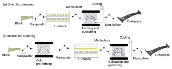
Figure 1.
Hot stamping methods. (a) Direct hot stamping, (b) indirect hot stamping.
During the process of the hot stamping, the structure of the material is transformed from ferritic–perlitic into martensitic. A high cooling rate of at least 27 K/s is required for such transformations [9]. For this purpose, tools with specially designed cooling channels are used [10].
The material of the drawpiece after the process of the hot stamping can reach the tensile strength within limits of 1500–1900 MPa. This technology also allows the production of the drawpieces with variable mechanical parameters. In such cases a special tool, in which we can separate a heated-up zone and a cooled zone is used. In the heated-up zone of the tool, non-martensitic transformation occurs in the shaped drawpiece, and the material features lower-mechanical parameters comparing to the ones in the water cooled zone [11].
When analyzing the technological process of the hot stamping, it has been noticed that the drawpieces (especially having more complicated shape), after removing them from the stamping die, have a tendency to uncontrolled distortions. This belongs to one from the reasons of lacking conformance of shape-dimensional accuracy with the design documentation of produced drawpieces. This non-conformance can be observed when the final stamping die was already produced and a batch of prototype drawpieces was produced as well. Within industrial practice, to compensate for these non-conformances it is necessary to change the shape of the working surfaces of the stamping die. To do this, a locksmith’s operations such as hardfacing, milling, grinding, slurring, etc., are performed. The obtaining of such a shape of the working surfaces of prototype tools, in order to be able to produce a final drawpiece complying with the design documentation with respect to shape and dimensions, is the final objective of these operations. Such an approach generates high costs (locksmithing work, many times repeated tests and attempts). The results of the research presented in this paper are aimed at the evaluation of the value and shape of the hardening distortions in the drawpieces produced with the use of the hot stamping method, and compensated for with the use of computer simulations. The compensation consists in a suitable modification of the shape of the working surfaces of the tools in such a way that the produced drawpiece complies with the expected shape and dimensional accuracy.
The presented paper constitutes a new approach to solving problem of compensation of the hardening deformations. With use of numerical simulations, it has been checked whether the phenomenon of the hardening deformations would appear in a given hot stamping process; the value of the deformations was calculated and compensated for by modifying the shape of the forming surfaces of the stamping die.
Based on industrial experience of the author of this publication, the following proprietary division of the distortions due to their shape was proposed:
- Flexure—flexure of the drawpiece after removal from the stamping die belongs to dominant form of the distortion;
- Torsion (skewing)—torsion of the drawpiece around imaginable axis of the drawpiece, after removal from the stamping die also belongs to dominant form of the distortion.
Numerical simulations of the hot stamping process were performed for representative drawpieces featuring hardening distortions, which can be allocated to two the above specified types.
2. Hardening Distortions—Source of Origin
The hardening distortions result from action of internal stresses generated during heat treatment operations, especially during cooling down [11,12,13]. It is possible to isolate two phenomena that occur inside hardened machinery parts when they are cooled down. The first phenomenon consists in the growth of volume, caused by the transformation of the crystalline structure from the thick packing of atoms (austenite) into a crystalline structure with a more thin packing of the atoms (ferrite, cementite and martensite). The second phenomenon consists in generation of internal stresses inside heat treated machinery parts, being the result of big thermal shrinkage during the cooling process. Increasing volume, caused by transformation of austenite into martensite during the cooling process, is the dominant phenomenon having an effect on the generation of the internal stresses [14,15]. The change of volume gets bigger as the the cooling rate increases, when the material loses its ability to adapt to change of the volume. At the same time the thermal shrinkage is generated. Both phenomena, as their final effect, cause distortions and dimensional changes of the hardened element [12,16].
3. Torsional Form of the Hardening Distortions
A beam from a car’s door panel was selected to analysis of the hardening distortions having form of the torsion.
3.1. FEA Models and Materials
The stamping die, the punch, the die and blankholder were discretized with rigid finite elements of superficial type. The blank was discretized with 2D finite elements of the EPS 11 (elasto-plastic shell) type. These elements have the shape of a triangle with five degrees of freedom (two translations along tangent vector, one along normal vector, and two rotations along tangent vectors). The elements have got eleven integration points along its thickness. These elements are consistent with the Reissner–Mindlin theory [17]. The model of the blank was assigned the material properties of 22MnB5 steel. The card of the material model is presented in Figure 2.
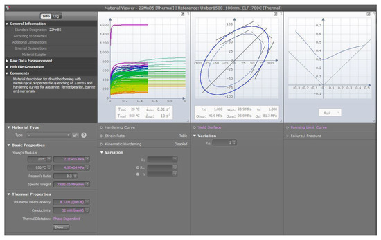
Figure 2.
Card of the 22MnB steel, the material model.
The model comprises data about strengthening curves of the material, investigated in various deformation speeds ( = 0.01 s−1–10 s−1), and various temperatures (t = 20 °C–900 °C), it also contains data on the dependency: temperature—time—transformation. It allows depicting all phenomena connected with transformation of metallurgical phases and shrinkage, occurring in the material during the hot stamping.
Interaction between the working surface of the tool and the blank was modeled using the contact type finite elements (solved by the Penalty algorithm) with friction having friction coefficient equal to 0.5 [18].
The structural design of the selected beam is shown in the Figure 3a. It is the beam with the following dimensions: length 1000 mm, width 150 mm, thickness 1 mm. The analysis of the hardening distortions during the press forming process was performed with use of the AutoForm v 8 system (AutoForm Engineering GmbH, Switzerland). In the first succession, one selected the shape of the blank and developed CAD (Computer Aided Design) models of the working surfaces of the tools, i.e., stamping die, punches and die clamps, which in the next step were used to construction of discrete models of the tool and the blank (Figure 3b).
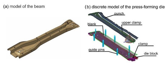
Figure 3.
(a) The CAD (Computer Aided Design) model of the beam, (b) discrete model of the stamping die.
For the developed model of the stamping die and the blank, the kinematics of the stamping process were defined along with the thermal and mechanical parameters. The values of these parameters were as follows:
- –
- Stamping speed 80 mm/s,
- –
- Ambient temperature 20 °C,
- –
- Thermal conductivity coefficient from the blank to the stamping die 3.5 , this coefficient was scaled depending on value of the pressure between the punch, the stamping die, and the blank,
- –
- Thermal conductivity coefficient from the blank, the punch, and the stamping die to the environment, linearly variable and dependent on temperature of the blank and the stamping die (for 20 °C equal to 0.02 ), for 950 °C equal to 0.075 ),
- –
- Temperature of the stamping die—150 °C,
- –
- Pressure force to the drawpiece during quenching 1500 kN,
- –
- Quenching time 8 s.
The above specified values of the thermo-mechanical parameters are recommended and confirmed in practice by the producer of the Autoform software, and such values should be taken to simulation of the hot stamping processes.
The model built in such a way underwent an analysis of the stamping and quenching process. It was coupled with a thermo-mechanical analysis of an implicit type.
3.2. Analysis Results
Figure 4 presents the most important results of the simulation.
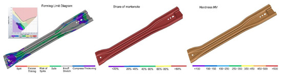
Figure 4.
Results of the simulation of the hot stamped door beam.
Making an analysis of results of the simulations presented in the Figure 4, it is possible to ascertain that the proposed technological process of the hot stamping fulfills the technical requirements. There was no risk of the occurrence of zones with wrinkles or cracks on the drawpiece, as confirmed. Only the allowable thinning of the drawpiece (15%) was found. The drawpiece obtained the required hardness (above 450 HV) and martensitic structure (above 80%).
Analyzing the hardening distortions of the drawpiece, the distortions were compared to the reference model, fitting them in the reference points system (RPS) [19,20] points, in which the distance of the reference model from deformed model equals to zero. In the Figure 5 is shown distortion of the model determined in relation to the reference model, which was fitted in the RPS points.
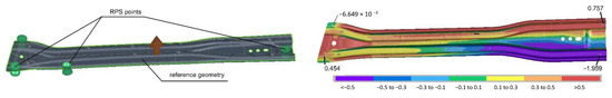
Figure 5.
Distortion of the beam evaluated in the reference points system (RPS).
The values of the hardening distortions exceed allowable values of the shape-dimensional tolerances (−1.959 mm) which were defined in the design documentation of the analyzed beam (±0.3 mm). The question arises: how to rectify shaping surfaces of the tools (punches, stamping dies and die clamps) to compensate the hardening distortions of the drawpiece? The Autoform Compensator tool was used for this purpose [21].
This tool automatically deforms shape of surface of the tools (the punch and the stamping die). The deformation direction of the surface of the tools is opposite to the direction of the hardening deformations of the drawpiece. The process is iterative, so as to obtain, after a few iterations, the drawpiece with compensated hardening deformations. The process of compensation can be controlled during each iteration by use of the compensation factor, which is responsible for the deformation force of surface of the tools. The higher the compensation factor, the lower the number of compensating iterations that need to be performed to compensate the hardening deformations of the drawpiece. It is recommended to select this factor so that the hardening deformations are compensated in 4–5 iterations. Figure 6 presents the method of operation of the Autoform Compensator tool.
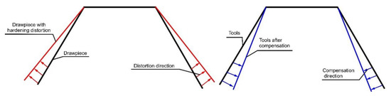
Figure 6.
Method of operation of the Autoform Compensator tool.
To compensate the hardening deformations of the drawpiece, it defines the surfaces of the tools, of which the shape will be corrected in the course of compensation. To make the compensation, a geometrical model of the stamping die with the punch, upper and lower die clamp was selected.
Figure 7a presents the results of the hardening distortions after compensation of the shaping surfaces of the tools, measured against the reference model, and fitted in the RPS points, while Figure 7b shows the CAD models of the punch before and after the compensation.
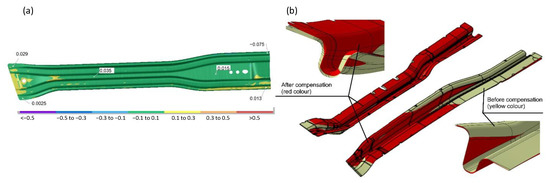
Figure 7.
(a) Hardening distortions of the beam after the compensation, (b) CAD models before and after the compensation.
4. Hardening Distortions Having Form of Flexure
For analyses of the hardening distortions with the flexure as their dominant form, the inner panel of the B pillar of a car body structure was chosen. This is element with the following dimensions: length 1000 mm, maximal width 200 mm. Furthermore, the inner panel of the B pillar was reinforced with the patch. The CAD model of the B pillar is presented in the Figure 8a. For the needs of the FEM analysis of the stamping process it has been developed using CAD models and discrete FEM models of the stamping die, the punch and the die clamps (Figure 8b). Additionally, we defined the position of the datum guiding pins, and defined the friction ratios between the elements of the tool and the blank. The kinematics of the stamping process was also defined.
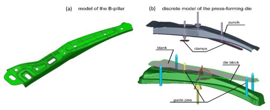
Figure 8.
(a) CAD model of the B pillar, (b) discrete model of the stamping die.
As shown above, the model has been calculated using the thermosolver module of the Autoform system. Analyzing the results of the simulation it is possible to ascertain that proposed technological process of the hot stamping complies with the technical requirements. No risk of occurrence of zones with wrinkles or cracks was confirmed in the drawpiece. Allowable thinning (15%) of the drawpiece was also not exceeded. The drawpiece obtained required hardness and structure. The hardening distortions of the B pillar were analyzed in a similar way as in the case of the door’s beam of a car body structure. In the Figure 9 are presented distortions of the model of inner panel of the B pillar against the reference model.
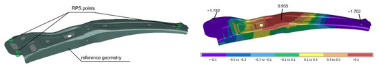
Figure 9.
Distortion of the model of inner panel of the B pillar evaluated in the RPS points.
The character of the hardening distortions depicted in Figure 9 indicates the flexure as the dominant form of the distortion. Figure 10 presents the most important results of the simulation: the forming limit diagram, martensite share and the hardness.
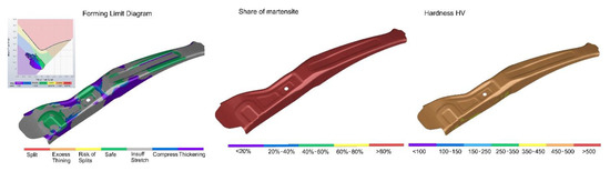
Figure 10.
Simulation results of the hot stamping of inner panel of the B pillar.
Analyzing the results shown in the Figure 10, it can be said that there was no risk of the occurrence of zones with wrinkles or cracks, as confirmed in the drawpiece. The allowable thinning of the drawpiece (15%) was confirmed. The drawpiece obtained the required hardness (above 450 HV) and martensitic structure (above 80%).
The center of the model was moved upwards, while its end was downwards. The values of the hardening distortions surpass allowable values of the shape-dimensional tolerances as defined by the technical documentation. The procedure was similar to the one as described in the case of the hardening distortions of the door’s beam was implemented. The geometrical models of the stamping die, the punch, upper and lower die clamp, were selected to the compensation. A new set of the models of working surfaces of the die block (stamping dies, punch, upper and lower die clamps) was obtained as a result of the performed analysis of the compensation. The simulation of the hot stamping process was repeated for the new model. In the Figure 11a are presented values of the hardening distortions after the compensation, measured in relation to the reference model, fitted in the RPS points, while in Figure 11b shows the CAD models of the stamping die before and after the compensation.
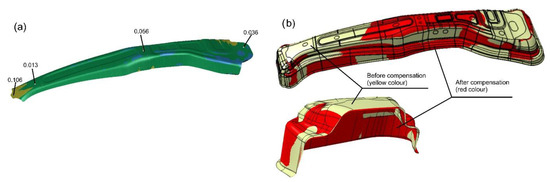
Figure 11.
(a) Hardening distortions after the compensation, (b) CAD model of the punch before and after the compensation.
Making an analysis of the obtained results of the hardening distortions shown in the Figure 11a, it can be noticed that the distortions are considerably lower, assuring production of the drawpieces with the assumed shape and dimensional tolerance.
5. Experimental Verification of Results of the Analysis and Discussion
In order to verify the proposed compensation method of the hardening distortions, we developed and manufactured stamping dies for the production of the door beam and the inner panel of the B pillar. In the shaping of the surfaces of the drawpiece in the stamping die and punches, surfaces with compensated hardening distortions were used that were determined in the course of computer simulations described in this paper. In the Figure 12a is shown the photo of the punch of the stamping die to the production of the door beam, while in the Figure 12b the photo of punch of the stamping die to production of the inner panel of the B pillar.
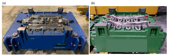
Figure 12.
(a) Photo of punch of the stamping die to production of door beam, (b) photo of punch of the stamping die to production of inner panel of the B pillar.
For testing purposes of the shape-dimensional accuracy and testing of the mechanical parameters, 50 pieces of the door beams and 50 pcs. of the inner panels of the B pillar were produced. The Figure 13a shows the photo of the door beam, and in the Figure 13b is shown the photo of the inner panel of the B pillar, which was produced for verification purposes of shape and dimensional accuracy and verification of the mechanical parameters.
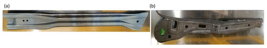
Figure 13.
(a) Photo of the door beam, (b) photo of inner panel of the B pillar.
5.1. Testing of the Shape-Dimensional Accuracy
Commencing verification of the shape and dimensional accuracy of produced drawpieces, at the beginning we analyzed the metrological requirements defined in the technical documentation of the drawpieces. Based on this analysis, tolerances for production of the both kinds of the drawpieces were divided into 3 groups, depending on the size of the tolerance field. For the inner panel of the B-pillar, these were: (−0.5 +0.5); (−0.7 +0.7) (−0.2 −0.7), while for the door beam (−0.3 +0.3); (−0.5 +0.5) (−0.2 −0.5). This was the base to prepare the measurement plan on the coordinate measuring machine, aimed at the selection of the number and location of the measurement points, and it was the base to define guidelines and recommendations for analysis of the measurement data. The measurements were made on the Zeiss Accura II coordinate measuring machine. Making an analysis of the shape and dimensional accuracy of the drawpieces, they were compared to the reference model by fitting them at the RPS reference points. Location of the RPS points in course of the measurements was the same as the one taken during analysis of the hardening distortions, which was described in the chapters 3 and 4.
The measurement of the door beam was carried out in 198 points, while the inner panel of the B pillar was measured in 160 points. Fifty pieces of each type of produced drawpiece have been measured (50 pieces of the inner panels of the B pillar and 50 piecess of the door beams). Figure 14a presents the exemplary results of the inner panel of the B pillar, whilst in Figure 14b the exemplary results of the door beam are shown.
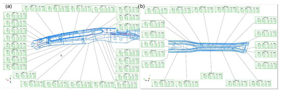
Figure 14.
(a) Measurement results of the inner panel of the B pillar, (b) the door beam.
Table 1 specifies the maximal values, minimal values and standard deviation of the measurement points of the door beam and the inner panel of the B pillar

Table 1.
The maximal values, minimal values and standard deviation the measurement points of the door beam and the inner panel of the B pillar.
Making an analysis of the measurement reports, it can be stated that the assumed manufacturing tolerances for the drawpiece were not exceeded from the measured points. The shape and dimensional accuracy of the both drawpieces is at the level required by design engineers. This means that the developed compensation strategy of the hardening distortion has brought good results.
5.2. Testing of the Mechanical Parameters
The mechanical parameters of the steel after process of stamping and hardening are very important in the case of hot-stamped drawpieces. It is assumed that the steel should have the following mechanical properties: yield strength Rp0.2 = 950 ÷ 1200 MPa, tensile strength Rm = 1300 ÷ 1650 MPa, and hardness HV = 400 ÷ 550. The hardness, the tensile strength and the yield strength were checked in 10 selected measurement points. Such points were selected bearing in mind the results of temperature measurements of the punches and the stamping dies in course of the production. In the vicinity of these points the punches and the stamping dies have shown the highest temperature (about 180 °C), which could result in worsened conditions of quenching and with the possibility of not having obtained the required mechanical parameters. Figure 15a shows the measurement points of the inner panel of the B pillar, while Figure 15b presents the measurement points of the door beam.
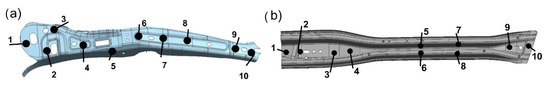
Figure 15.
The measurement points of (a) the inner panel of the B pillar, and (b) the door beam.
To test the mechanical parameters, the non-destructive method was implemented using the 3MA device made by the Franchoufer Institution [22]. This device measures the mechanical parameters of ferromagnetic steels and was calibrated to steel of the 22nB5 grade after the hardening treatment. Table 2 presents the maximal values, minimal values and standard deviations from all performed measurements of hardness, tensile strength and strength limit of the beam and the inner panel of the B pillar.
Table 2.
The maximal values, minimal values and standard deviations from all performed measurements of hardness, tensile strength and strength limit of the beam and the inner panel of the B pillar.
Analyzing the measurement data, it is possible to ascertain that:
- From the measurement points in each, the material of the both drawpieces has reached its required hardness, which was within assumed range from 400 to 550 HV;
- The yield strength in each from the measurement points has the required values, from 950 to 1200 MPa;
- The tensile strength has also reached the required value in range of 1300–1650 MPa in each from the measurement points.
5.3. Testing of the Mechanical Parameters
In order to check microstructure of the steel after the hardening, the test pieces were taken from appropriate zones of the drawpieces (Figure 16a,b). The location of these zones was selected based on the results of the FEM simulation of the hot stamping process. The results of the simulation have shown that a problem with martensitic structure may appear in these areas.
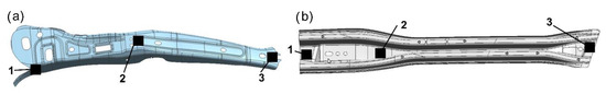
Figure 16.
Areas of the test pieces were taken to the tests of microstructure of (a) the inner panel of the B pillar, and (b) the door beam.
After suitable preparation of the test pieces, they were observed using an AmScope ME1200TC-5M microscope (Irvine, CA, USA). Figure 17 presents photos of image from the microscope, which show the structure of the test pieces taken from the measurement point no. 1.
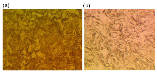
Figure 17.
Microstructure of the steel, (a) from point no. 1 at inner panel of the B pillar, and (b) from point no. 2 at the door beam.
Analyzing the photos presented in the Figure 17 it can be stated that they show the martensitic structure. This is expected structure of the steel for the drawpieces formed in the hot stamping process.
6. Conclusions
Making use of advanced CAE systems, it is possible to analyze and solve the complex problem of compensation of the hardening distortions, occurring during production of a drawpieces with the use of hot stamping technology.
To correctly solve this task, the following steps need to be taken:
- -
- The defining requirements for the dimensional and shape tolerances of the analyzed drawpieces;
- -
- Verifying if the shape of the drawpiece is technologically feasible—i.e., is possible to be produced in process of the hot stamping;
- -
- Developing a plan of technological process to produce the drawpiece, considering all requirements and restrictions of integrated processes of plastic forming and heat treatment;
- -
- Developing a method how to set datum positions of the drawpiece in the tool;
- -
- Constructing superficial CAD models of the working tools (stamping dies, die clamps, punches);
- -
- Elaborating technical assumptions of the hot stamping technology (temperature of the blank, time of transfer of the blank from furnace to press, time of stamping operation, course of speed motion of ram of the press, time of hardening, temperature of the tools, required hardness of the drawpiece, model of the material for specified thickness of drawpiece);
- -
- Defining the shape of the blank, which assures obtaining finished drawpiece in required manufacturing tolerance of external outline of the blank;
- -
- Constructing FEM models of the blank and working surfaces of stamping die, defining all its components, kinetic and thermal parameters;
- -
- Carrying out simulation and analyzing results of the simulation in view of the characteristic, which would ensure correct plastic working (FLD diagrams and thinning) and the heat treatment (distribution of the hardness and martensite);
- -
- Analyzing the results of the simulation in view of the values of the hardening distortions in the drawpiece, in relation to the requirements of the shape-dimensional tolerances specified in the technical documentation.
In cases where the hardening distortions have values higher than required, analysis of compensation of these distortions needs to be performed. Such analysis is performed in the following steps:
- -
- Creating a model to calculate the compensation of the hardening distortions and executing analysis of the hardening compensation at assumed parameters of the compensator;
- -
- Analyzing the obtained compensation results of the tool in view of the hardening distortions of the drawpiece; in the case when the hardening distortions are still too high, carrying out the next loop of the calculations. The loops are repeated till obtaining the drawpieces having the hardening distortions within the assumed field of the tolerances;
- -
- Memorizing compensated superficial CAD models of the tools, which in the course of the next steps are to be used by tool design engineers as the base surfaces to develop the manufacturing tools.
Figure 18 presents a scheme of the process during analysis of the compensation of the hardening distortions.
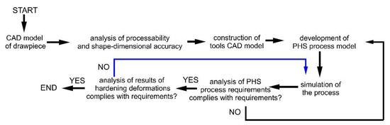
Figure 18.
Scheme of the process when analyzing compensation of the hardening distortions.
The author’s proprietary method of compensation of the hardening deformations using numerical calculations, as presented in Figure 18, is a new approach to solving problems of the shape and dimensional inaccuracies of drawpieces produced by hot stamping. The method has given very good results for the two tested typical car body elements: the inner panel of the B-pillar and the door beam. This method allows the prediction and compensation of the hardening deformations of stamped elements, produced in the hot stamping technology, as early as at the designing stage of the process, and with a significant reduction of the high manufacturing costs of tools (dies). The proposed compensation methodology of the hardening distortions has given good results for two tested typical car body elements: the inner panel of the B pillar and the door beam. Results of numerical compensation of the hardening distortions were verified experimentally. The shape and dimensional accuracy, mechanical parameters and microstructure of the steel for the test batch of produced drawpieces complied with the requirements for such type of the products.
Funding
This research received no external funding
Institutional Review Board Statement
Not applicable.
Informed Consent Statement
Not applicable.
Data Availability Statement
The data is available on reasonable request from the corresponding author.
Conflicts of Interest
The author declares no conflict of interest.
References
- Mori, K.; Bariani, P.F.; Behrens, B.A.; Brosius, A.; Bruschi, S.; Maeno, T.; Merklein, M.; Yanagimoto, J. Hot stamping of ultra-high strength steel parts. CIRP Ann. Manuf. Technol. 2017, 66, 755–777. [Google Scholar] [CrossRef]
- Miyanishi, M. Manufacturing of Light Weight Cars. In Proceedings of the 13th International Conference on Metal Forming, Toyohashi, Japan, 19–22 September 2010. [Google Scholar]
- Ping, H.; Dongyong, S.; Liang, Y.; Guozhe, S.; Wenquan, L. The finite element analysis of ductile damage during hot stamping of 22MnB5 steel. Mater. Des. 2015, 69, 141–152. [Google Scholar]
- Cui, J.; Lei, V.; Xing, Z.; Li, C. Microstructure distribution and mechanical properties, prediction of boron alloy during hot forming using FE simulation. Mater. Sci. Eng. 2012, 535, 121–132. [Google Scholar] [CrossRef]
- Feuser, P.; Schweiker, T.; Merklein, M. Partially Hot-Formed Parts from 22MnB5 – Process Window, Material Characteristics and Component Test Results. In Proceedings of the 10th International Conference on Technology of Plasticity 2011, Aachen, Germany, 25–30 September 2011; pp. 408–413. [Google Scholar]
- Karbasian, H.; Tekkaya, A.E. A review on hot stamping. Mater. Process Technol. 2010, 210, 2103–2118. [Google Scholar] [CrossRef]
- Ping, H.; Liang, Y.; Bin, H. Hot Stamping Advanced Manufacturing Technology of Lightweight Car Body; Springer: Berlin/Heidelberg, Germany, 2017. [Google Scholar]
- Gronostajski, Z.; Pater, Z.; Madej, L.; Gontarz, A.; Lisiecki, L.; Lukaszek-Solek, A.; Luksza, J.; Mróz, S.; Muskalski, Z.; Muzykiewicz, W.; et al. Recent development trends in metal forming. Arch. Civ. Mech. Eng. 2019, 19, 898–941. [Google Scholar] [CrossRef]
- Neugebauer, R.; Schieck, F.; Polster, S.; Mosel, A.; Rautenstrauch, A. Press hardening-An innovative and challenging technolog. Arch. Civ. Mech. Eng. 2012, 12, 113–118. [Google Scholar] [CrossRef]
- Chen, J.; Gong, P.; Liu, Y.; Zheng, X.; Ren, F. Optimization of hot stamping cooling system using segmented model. Int. J. Adv. Manuf. Technol. 2017, 93, 1357–1365. [Google Scholar] [CrossRef]
- Merklein, M.; Lechler, J.; Stoehr, T. Investigations on the thermal behavior of ultra high strength boron manganese steels within hot stamping. Int. J. Mater. Form 2009, 2, 259–262. [Google Scholar] [CrossRef]
- Nakagawa, Y.; Mori, K.; Maeno, T. Springback-free mechanism in hot stamping of ultra-high-strength steel parts and deformation behaviour and quenchability for thin sheet. Int. J. Adv. Manuf. Technol. 2018, 95, 459–467. [Google Scholar] [CrossRef]
- Liu, H.; Liu, W.; Bao, J.; Xing, Z.; Song, B.; Lei, C. Numerical and Experimental Investigation into Hot Forming of Ultra High Strength Steel Sheet. ASM Int. 2011, 20, 1–10. [Google Scholar] [CrossRef]
- Dunwen, Z.; Chuanzhen, H.; Ming Ch Jun, L.; Guo, J. Hot Forming Springback and Control of 22MnB5 Boron and Magnesium Alloy Sheet. Key Eng. Mater. 2012, 499, 96–101. [Google Scholar]
- Hongsheng, L.; Jun, B.; Zhongwen, X.; Baoyu, S.; Yuying, Y. Analysis of Mechanism of Springback in 22MnB5 Super-high Strength Steel Forming. Acta Aeronaut. Austronautica Sin. 2010, 31, 865–870. [Google Scholar]
- Bao, J.; Liu, H.; Xing, Z.; Song, B.; Yang, Y. Springback of hot stamping and die quenching with ultra-high-strength boron steel. Eng. Rev. 2013, 3, 151–156. [Google Scholar]
- Yu, W.; Hodges, D.H.; Volovoi, V.V. Asymptotic generalization of Reissner–Mindlin theory: Accurate three-dimensional recovery for composite shells. Comput. Methods Appl. Mech. Eng. 2002, 191, 5087–5510. [Google Scholar] [CrossRef]
- Yanagida, A.; Azushima, A. Evaluation of coefficients of friction in hot stamping by hot flat drawing test. CIRP Ann. Manuf. Technol. 2009, 58, 247–250. [Google Scholar] [CrossRef]
- Bibek, R.; Shenglan, L. RPS Alignment of Automotive Body Parts in Virtual Assembly and Deviation Analyses. Int. J. Sci. Eng. Res. 2016, 7, 562–570. [Google Scholar]
- Arámbula, K.; Siller, H.R.; De Chiffre, L.; Rodríguez, C.A.; Cantatore, A. Evaluation of metrology technologies for free form surfaces. Int. J. Metrol. Qual. Eng. 2012, 3, 55–62. [Google Scholar] [CrossRef][Green Version]
- Autoform. In Autoform Built-In Help System; Olivier Leteurtre: Zurich, Swiss, 2021.
- Available online: https://www.izfp.fraunhofer.de/content/dam/izfp/de/documents/aktuelles/2015/Themenflyer/3MA-presshaerten-en.pdf (accessed on 1 February 2021).
Publisher’s Note: MDPI stays neutral with regard to jurisdictional claims in published maps and institutional affiliations. |
© 2021 by the author. Licensee MDPI, Basel, Switzerland. This article is an open access article distributed under the terms and conditions of the Creative Commons Attribution (CC BY) license (http://creativecommons.org/licenses/by/4.0/).