Abstract
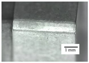
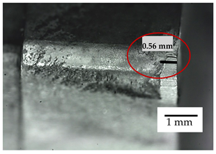
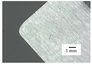
In recent years, coated cemented carbides have often been the first choice for a wide variety of tool inserts and applications. Its success as a cutting tool material arises from the unique combination of wear resistance and toughness, and its ability to be formed into complex shapes. The structure obtained by sintering nanoparticle powders provides a significant improvement in product properties, such as higher cutting speeds, lower tool tolerances, and longer service life. In this study, a multi-layered gradient coating, deposited on nanostructured cemented carbides by plasma-assisted chemical vapor deposition (PACVD) was investigated with emphasis on its wear and exploitation properties. TiBN coating was deposited on nanostructured cemented carbide samples with the addition of 5 wt% Co, 10 wt% Co and 15 wt% Co. The samples were consolidated by one cycle hot isostatic pressing (HIP) technique. Complex architecture built of TiN and TiB2 gradient multilayer sequence block was deposited on each type of substrate. Wear resistance of the obtained samples was determined by erosion wear testing and dry sliding wear testing (ball-on-flat test). The friction coefficients of ~0.22 obtained for coated samples by the ball-on-flat test show a decrease in friction when compared to uncoated samples values of ~0.32. The absence of coating rupture was confirmed by wear track depth measurements showing a wear trace depth of ~1.2 μm. Exploitation properties i.e., tool life determination of samples was obtained using single-point turning tool test and compared to commercial cutting tool insert type K10 tested under the same conditions. All the conducted tests show excellent wear and exploitation properties of the newly developed TiBN coating under chosen conditions, including cutting speed, vc = 200 m/min, depth of cut, ap = 1 mm, and feed, fn = 0.2 mm. Coated WC-Co samples with 15 wt% Co, having withstood 15 min of machining with flank wear trace size less than 0.3 mm, suggest significant improvement when compared to trace size of 0.56 mm obtained for K10 commercial cutting insert.
1. Introduction
The development of new cutting tool materials with superior characteristics and performance, including prolonged tool service life, higher cutting speeds and loads, and lower production costs is one of the most researched areas of cemented carbides application. Tooling cost is not only derived by the initial material and energy input, but also strongly depends on cycle time, i.e., cutting tool replacement time [1]. Coated tools have been shown to meet the high demands of different cutting processes. Cemented carbides are currently one of the major representatives of cutting tools materials for machining different metallic alloys [2]. One of the main issues concerning coated tool materials is achieving proper adhesion between substrate and coating since it has shown to have a major impact on the cutting tool wear resistance and its service lifetime [2,3,4]. Among many types of coatings (Ti,Al)N systems have exhibited excellent properties while being relatively easily deposited on cemented carbide substrates [5]. Besides coating adhesion quality, the content of cemented carbide binder is another critical factor influencing wear and exploitation characteristics of the tool material. Co binder used during sintering has been shown to promote the toughness of the tool material, but at the same time reduces coating adhesion [6,7]. Therefore, finding an optimum Co binder content is a major step in designing a cemented carbide substrate composition. To minimize the negative impact of Co binder on coating adhesion, chemical etching and other types of surface treatments before coating, are often applied [8].
In the recent years plasma-assisted chemical vapor deposition (PACVD)process was used for tool coating, allowing high-quality coating without decarbonization or other types of cemented carbide defects. PACVD has also been shown to promote toughness and wear resistance of cemented carbide tool materials. TiN, TiCN, and (Ti,Al)N coating deposited on tools provide excellent performance in interrupted cutting processes, such as grooving and milling. PACVD process combines advantages of coatings obtained by the chemical vapor deposition (CVD) process, with low substrate temperatures characteristic of the physical vapor deposition (PVD) process [9]. As nanostructured cemented carbide substrates are very reactive, both in the sintering phase and in the coating phase, chemical vapor phase evaporation (CVD) conducted at about 1000 °C causes microstructural defects that disrupt one of their most important properties, i.e., toughness. The PACVD process, using plasma, lowers that coating temperature to approximately 500 °C eliminating such mechanical property degradation.
Due to the high temperatures that develop during cutting processes (>700 °C), the required properties of tool materials are primarily related to high hardness, high wear resistance and thermal stability of the properties, giving them an advantage over high-speed steel tools [10]. Thin hard coatings on a softer and tougher substrate have proven to be a good combination in extending the performance characteristics of tools. Nowadays, the use of hard coatings has only one significant limitation, i.e., high stresses in the coatings themselves and at the substrate/coating interface [11]. Internal stresses are most likely to occur when the coating temperature is higher than the working temperature of the tool [12]. Titanium nitride (TiN) and titanium carbide (TiC) coatings have proven to be particularly suitable for applications involving cutting tools, and for some other abrasive and erosive purposes [13]. However, the limitation of these coatings is the high friction coefficient compared to, for example, titanium carbonitride coating (TiCN) [14]. When considering multilayer coatings, the goal is to create such a coating architecture in which each layer, with its specific properties, would contribute to the characteristics of the coating itself. Multilayer coatings can provide higher hardness and toughness along with higher strength and better resistance to adhesion and abrasion [15]. The reason for such properties and behavior of coatings is scarcely investigated, but it is assumed that an increase in the number of obstacles to the movement of dislocations in the interlayers is crucial [16]. Structural and chemical compatibility of the coating and substrate or of different types of layers in multilayer coating results in low energy levels at the transition surface, thus, promoting high adhesion as is the case with TiN/VC and TiC/TiB2 systems [17]. The architecture of such coatings can range from simple single layer to complex multilayer, gradient, or composite, as schematically shown in Table 1.

Table 1.
Different coating structures [18].
Cutting tools present the most demanding applications of cemented carbides. Depending on the cutting method, operating conditions, and machined material, these tools show several characteristic wear patterns. They are common to turning, milling, cutting, reaming, occurring on both coated and uncoated tools. During cutting, the material layer is removed from the workpiece surface with a wedge-shaped tool with local blade pressure of up to 2000 MPa and a maximum temperature of up to 1000 °C. The result is a separated particle that is guided over the rake face of the tool. The heat developed in the tool/workpiece contact during cutting can cause hardness decrease and originates from several processes [19]:
- 80% generated by the deformation of the separated particle,
- 18% generated by friction between the separated particle and the rake face of the tool,
- 2% generated due to the cutting blade deformation.
During operation, the surface layers of tools are exposed to high mechanical stresses. To withstand those stresses and secure wear resistance, cutting materials should exhibit both high hardness and high fracture toughness [20]. Despite the general opinion that hardness and toughness being at the opposite side of the properties range [21,22], some studies show different correlation, especially for materials of lower hardness values, where using higher content of binder along with smaller carbide grain, did not result in a toughness increase [23]. Alternatively, improvement of toughness with increasing binder content has been confirmed for cemented carbides of higher hardness at assigned to the breaking of carbide network via binder phase. For ultrafine and nanostructured cemented carbides, an increase in hardness had a less pronounced toughness lowering effect [24]. The strong correlation between the fracture toughness and wear mechanism to the microstructure of cemented carbides has been detected in many studies [25,26]. Grain size, carbide content and the type of binder have a crucial influence on cemented carbides wear resistance [27,28,29]. Analysis of microstructure as one of the wear-governing aspects detected higher resistance of fine carbide structure compared to coarse microstructure, regardless of hardness values, explained by greater crack resistance of each grain with their size reduction [30,31,32]. Brittle fracture, plastic deformation and fatigue were detected as key contributors to the cemented carbides wear.
As tool wear cannot be prevented but only slowed down, the aim is to establish such a tool/workpiece/machining relationship in which controlled wear occurs. Controlling wear, which includes flank wear, crater appearance, blade tip wear, and plastic blade deformation, is the only way to achieve planned production rates and cost. Coating of fine-grained cemented carbides with a thin coating of superior wear properties presents a rather interesting field of research, aimed at obtaining material systems with a specific combination of high hardness, improved fracture toughness and superior wear and friction properties [33,34].
In this study, three types of nanostructured cemented carbide samples with the addition of 5, 10 and 15 wt% Co were produced by the sinter HIP process. Substrates of cemented WC-Co were subsequently coated with complex gradient TiBN coating. Quantification of how this newly developed complex coating affects the properties and durability of cemented carbide samples was conducted by erosion wear testing (particle erosion) and determination of friction and sliding wear factors (pin on disc test). To test these samples in real machining conditions, in which the cutting blade is simultaneously exposed to different wear mechanisms, a single-point turning test was performed. The results obtained for produced WC-Co samples were compared to those of Group K cutting material samples, which were tested under the same turning parameters.
2. Materials and Methods
The geometry of commercially available cutting tool inserts, described in Widia Products Group catalog, code SNGN120408, was chosen as the sample shape. Samples of nanostructured cemented carbides were obtained from the sinter-HIP process, conducted in vacuum by single-cycle hot isostatic pressing described in detail in the literature [35]. With the sinter-HIP process, mixtures of nanopowder tungsten carbide (WC) powder, (H.C. Starck, Goslar, Germany) and cobalt powder (Co) (Umicore, Markham, ON, Canada) with the addition of vanadium carbide (VC) (Umicore, Markham, ON, Canada) and chromium carbide (Cr2C3) (H.C. Starck, Goslar, Germany) as grain growth inhibitors, were consolidated. Three different mixture compositions were produced, with 5, 10, and 15 wt% Co, respectively. The sintering was conducted at a temperature of 1350 °C at an inert argon gas pressure of 10 mbar for 30 min, followed by warm isostatic pressing for 45 min at a pressure of 100 bar, which resulted in theoretical sample densities without porosity.
Electron microscopy was performed on a field emission scanning electron microscope (FESEM, Ultra 55, Carl Zeiss AG, Munich, Germany). The mean value of WC grain size was determined by the line method on FESEM micrographs.
The PACVD coating of cemented carbide substrates was performed by system manufactured by Rübig GmbH (Marchtrenk, Austria), type PC 70/90. The surfaces of the samples were treated prior to coating to achieve better adhesion of the applied layer and possibility of subsequent coating quality analysis with emphasis on two tool surfaces: smooth and polished surface, and rough surface untreated after sintering (as-sintered). The coated polished surface was intended for coating characterization, while other tool surfaces were not grounded and polished. Parameters of sample preparation and testing methods which resulted in data shown in Table 2 and Table 3 are presented in detail in the literature [35].

Table 2.
Properties of WC-Co substrates [35].

Table 3.
Complex TiBN coating process [35].
The coating on this surface was expected to exhibit better adhesion, thus better exploitation properties. Complex architecture built of TiN and TiB2 layers, was deposited on four samples of each type of substrate with TiN as the backing layer, TiCN layer (using CH4 precursor) followed by a block composed of thirty graded TiN/TiB2 sequences, ending with a TiBC, TiN and TiB2 layers on top. During TiN/TiB2 sequence application, deposition time of the TiN layer was decreased with each step, while the application time of the TiB2 layer was increased. The flow of N2 was gradually reduced and at the same time the flow of BCl3, the precursor in charge of releasing boron, was increased accordingly. A gradual transition of layers was achieved so that a gradient multilayer coating deposition is ensured. TiCl4 was used as a titanium precursor. Parameters used to achieve described multilayer system with gradient transition between altering layers are given in Table 3 and steps of the PACVD process including structure of obtained coating are shown in Figure 1. The properties of obtained samples are presented in Table 4.
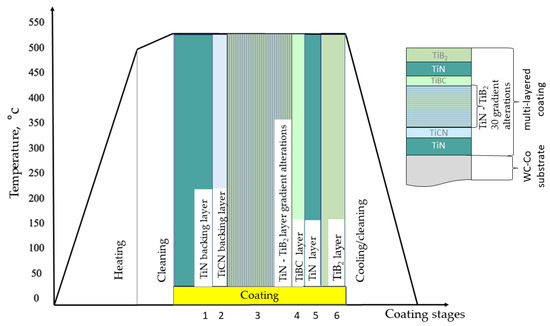
Figure 1.
Coating process stages and architecture.

Table 4.
Properties of coating/substrate systems [35].
The x-ray diffraction (XRD) analysis of all three types of coated samples was conducted using the XRD6000 diffractometer (Shimadzu Corporation, Tokyo, Japan) with CuKα radiation. Acceleration voltage of 40 kV and 30 mA current, in the 2θ range of 2 to 120° with a step of 0.02° and acquisition time of 0.6 s was applied. The obtained results indicated the hexagonal P-6m2 tungsten carbide (WC, ICDD PDF#51-0939) as major phase, Figure 2. Weak peak at 44° 2θ suggest presence of hexagonal P6/mmm titanium boride (TiB2, ICDD PDF#65-8698) in trace amounts. Cubic Fm-m3 titanium nitride (TiN, ICDD PDF#38-1420) weak and broader peak was obtained at 42° 2θ. This broader peak could indicate an additional phase present or titanium boronitride (Ti4N3B2, ICDD PDF#87-3790) overlapping with titanium nitride. Establishing a definite distinction of the titanium nitride and titanium boronitride phases was difficult since they have very similar diffraction patterns arising from them being isostructural phases [35].
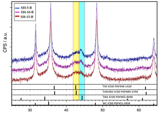
Figure 2.
XRD patterns of coated samples: SH-5-B, SH-10-B and SH-15-B [35].
Quantitative Depth Profile (QDP) analysis of the coating chemical composition was also performed by the GDOES method (GDOES—glow discharge optical emission spectroscopy) using a LECO SPECTRUMAT 750 GDS device (St. Joseph, MI, USA). Figure 3 shows the results of TiBN coatings on all three types of WC-Co substrate.
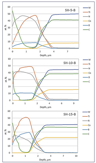
Figure 3.
Distribution of elements by depth for S-H-5-B, SH-10-B and SH-15-B.
Different distribution of chemical elements at different depths has been detected for all samples. TiBN coating consists of alternating layers of TiN and TiB2, ending with a layer of TiB2, as expected. However, due to the insufficient resolution of the device on which the GDOES analysis was performed, i.e., too thin layers of the coating, the device could not record abrupt changes in the chemical composition due to the gradient sequence of TiN and TiB2 layers along the entire depth of the coating. The presence of C and N in the top surface layer can be attributed to their diffusion originating from CH4 precursor and N2 used during TiN/TiB2 gradient sequence coating.
2.1. Erosion Wear Resistance Test
Particle erosion is the loss of material or coating from the surface of a solid body due to the relative motion (flow) of the fluid in which the solid particles are located. Particle erosion is a realistic phenomenon in any system where solid particles are present in a gaseous or liquid medium that collides with another solid body at a velocity greater than 1 m/s. The mechanism of erosion wear largely depends on the angle of incidence of the particles; therefore, two types of erosion occur:
- abrasive erosion (at a small impact angle)
- impact erosion (impact angle: 90°).
The erosion resistance of thin hard coating on different substrates was determined using the device shown in Figure 4. The sample rotates in a given path and hits the jet of erodent (SiO2; particles diameter: 0.063–0.355 mm) at a constant flow rate falling through the nozzle. Parameters used during erosion testing are presented in Table 5.
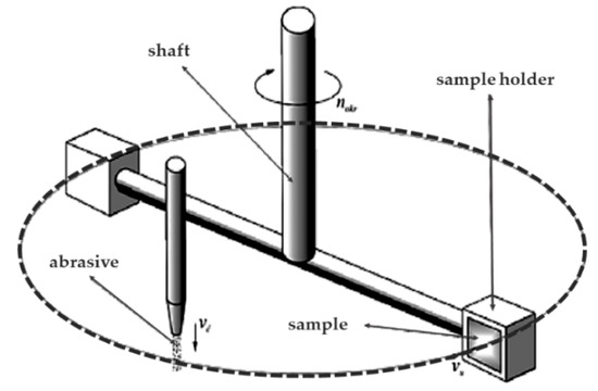
Figure 4.
Erosion resistance testing setup.

Table 5.
Parameters of erosion testing.
The quantification of erosion wear was obtained by measuring the loss of sample mass by sample weighing before and after erosion testing on a E. Mettler laboratory balance scale, type D5 #1262 (Zürich, Switzerland). These measurements performed with three repetitions on uncoated cemented carbides with 5, 10 and 15 wt.% Co and sample with 10 wt.% Co coated with TiBN coating. Traces of erosion were analyzed by scanning electron microscope, SEM (Tescan Vega TS 5136 MM, Brno-Kohoutovice; Czech Republic).
The 30° and 90° erodent impact angles were chosen to simulate two different erosion mechanisms, abrasive erosion for lower angle and impact erosion for the higher angle of impact. Although the 30° angle corresponds better to the machining conditions, i.e., chip movement, the 90° angle of erodent impact was chosen as an extreme case, in order to investigate the behavior of this coating in impact erosion conditions, thus, providing valuable data on the application of this novel material for purposes other than turning.
2.2. Friction and Sliding Wear Testing
The tribology properties of both the base material and coated samples in terms of resistance to dry sliding wear were tested by the ball-on-flat method using Oscillating tribotester manufactured by TRIBOtechnik (Clichy, France). The values of the friction coefficient without lubrication were determined by alternately sliding the ball Ø 6 mm, made of alumina (Al2O3) on the surface of the sample. The normal force of 10 N was applied, and the sliding distance was 60 m. This test was performed with three repetitions on the unpolished (as-sintered) surface of each sample, with roughness values presented in Table 6 to simulate real conditions during the operation. The testing parameters are given in Table 7.

Table 6.
Roughness parameters of coated samples [35].

Table 7.
Sliding wear test parameters.
After dry sliding wear testing, a wear trace profile was recorded on a VHX-2000 digital microscope manufactured by Keyence Corporation (Osaka, Japan). The wear track section area was measured to determine the wear factor K describing the sliding wear resistance according to the equation:
where: A—wear track section area, mm2; e—motion amplitude, mm; FN—normal force, N; s—sliding distance, m.
As a method for detecting possible full penetration through the coating during the ball-on-flat testing, wear trace depth was determined after friction testing. Depths of wear traces were obtained using Stylus instrument Perthometer S8P manufactured by Mahr Perthen (Göttingen, Germany).
2.3. Single-Point Turning Test
A single point cutting tool machinability test (turning test) was performed on produced samples with the aim of reproducing real machining conditions in which several wear mechanisms act on the cutting blade. The test was performed in accordance with ISO 3685:1993(R2017) [36] on a SBL 500 turning center manufactured by Trens SK, a.s. (Trenčín, Slovakia). The standard recommends a procedure for tool-life testing of high-speed steel, cemented carbides and ceramic single-point turning tools used on steel and cast-iron workpieces with defined cutting parameters, equipment, workpiece material, coolant, and method of tool wear assessment.
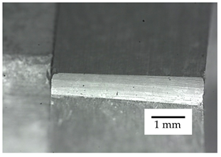
All types of cemented carbide substrates were tested, and the obtained results were compared with those for the uncoated substrate with 15 wt.% Co binder (SH-15) with hardness most similar to commercially available Group K materials. Steel grade C45E was selected as the workpiece material. For the wear behavior testing of the cutting tool, lubricant free machining was used. Processing was conducted with parameters identical to those for commercial tools of this type: Cutting speed, vc = 200 m/min; cutting depth, ap = 1 mm; offset, f = 0.2 mm. The tests were performed according to the guidelines given in Table 8. Prior to the test, the geometry of the cutting blade as a key feature of tool wear was controlled, and the uniformity of all cutting blades was confirmed. As no unambiguous criteria for assessing the tool blade wear were defined, the flank wear trace size greater than 0.3 mm after 15 min of machining was taken as the limit value. The tool sample geometry and its mounting in the tool holder are shown in Figure 5.

Table 8.
Turning Test Setup.
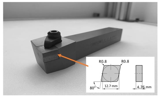
Figure 5.
Test specimen mounted in the tool holder.
Cutting process parameters, such as the workpiece material and insert style were selected to achieve plastic deformation as the main wear mode. The testing of tool wear was performed on a special tool positioning device with the recording optical system shown in Figure 6. Based on the desired resolution, the OEDG Opto Engineering (Grünwald, Germany) RT-mvBF3-2124a USB3 Vision camera with the TC4M009-C (OEDG Opto Engineering, Grünwald, Germany) telecentric lens, was selected for visual wear recording.
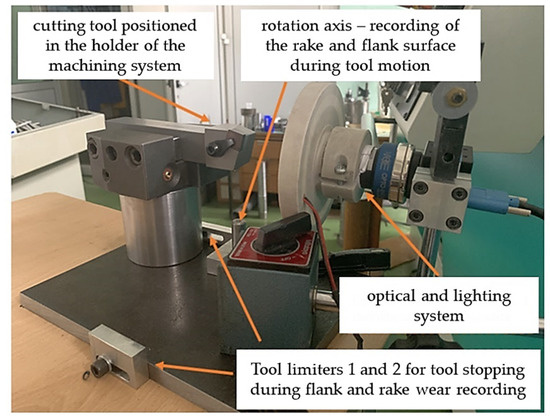
Figure 6.
Tool wear recording system setup.
3. Results
3.1. Results of Erosion Wear Resistance Test
The results obtained from erosion testing with erodent impact angle of 30° indicate more pronounce wear occurring for cemented carbide samples with higher Co binder, expressed as higher loss of sample mass. For an impact angle of 90° higher loss of mass is detected for samples with lower Co content. Figure 7 shows the surface of the SH-10 sample before and after erosion wear at an erodent intrusion angle of 90°. Significant surface roughening caused by the impact of erosive particles is detected. Impact erosion governed by plowing of hard erodent through the softer binder phase along with fractures and pulling out of brittle WC phase is the main contributor for the mentioned surface roughening. It should be noted that smearing of the extruded softer Co binder during erosion, also has a positive effect on surface wear, decreasing the friction at erodent/surface interface.
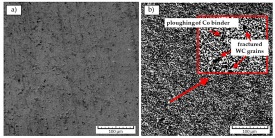
Figure 7.
SEM micrographs of the SH-10 sample before; and (a) after erosion wear; (b) at an angle of 90°.
In relation to the resistance of coatings to erosion wear, the test results showed excellent resistance of the multilayer coating. Coated samples generally performed better at a small particle intrusion angle where abrasive erosion is dominant. Visual traces of wear recorded on the TiBN layer are shown in Figure 8. Impact erosion prevailing at higher particle impact angles caused more pronounced wear of coatings and substrates. The coatings were completely stripped after 60 min of testing, nevertheless, showed better resistance than uncoated carbide base.
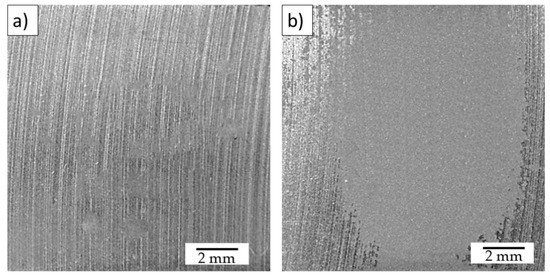
Figure 8.
Surface of the sample SH-10-B after erosion wear at an angle of 30°; and (a) 90° angle (b).
The results of erosion wear considering the loss of sample mass are shown in Table 9.

Table 9.
Results of erosion testing.
3.2. Results of Friction and Sliding Wear Testing
Figure 9 and Figure 10 show the mean values of the friction factors for the tested substrate/coating systems. Three tests were performed on each sample.
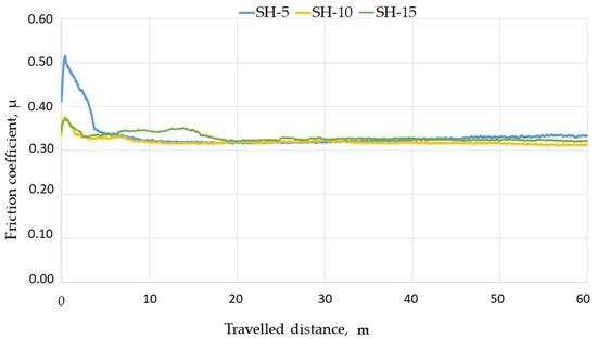
Figure 9.
Mean values of friction coefficients for uncoated samples.
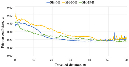
Figure 10.
Mean values of friction coefficients for coated samples.
A comparison of the obtained curves shows a higher friction factor for uncoated samples. It is obvious that the considered TiBN coating on cemented carbide samples greatly reduces friction, thus, increasing the resistance to dry sliding wear. The stronger variations of friction factors in TiBN coating at distances between 50 and 60 m, as shown in Figure 10, can be attributed to the coating entering and passing through different layers. The differences of the friction coefficient variations in a long running-in period involving 2/3 of the traveled distance should not be attributed to the coating architecture since it is the same in all tested samples. In that running-in period, the values of friction coefficients fall significantly as a result of sample surface smoothing, which is characteristic of all curves obtained by the ball-on-flat testing. The friction coefficient decrease observed for all three sample types during first 2/3 of test duration can be attributed to different initial roughness parameters of coated samples. The sharpest decrease in the friction coefficient can be observed for the SH-5-B, sample of the highest initial roughness. The smallest reduction of the friction coefficient was detected for the sample with the lowest roughness, the SH-15-B sample. Although, friction coefficient variations after 50 m of traveled distance imply entering the coating and its layers, the absence of coating rupture was confirmed by wear track depth measurements indicating depths between 1.18 μm and 1.21 μm, i.e., less than measured coating thicknesses of 1.61 μm to 1.65 μm.
Table 10 presents the results of individual measurements of the friction factors and volume loss determined by the “ball on plate” test, and Figure 11 shows the wear factor (K) values calculated according to equation 1.

Table 10.
Mean values of friction coefficient and volume loss in “ball on plate” test.
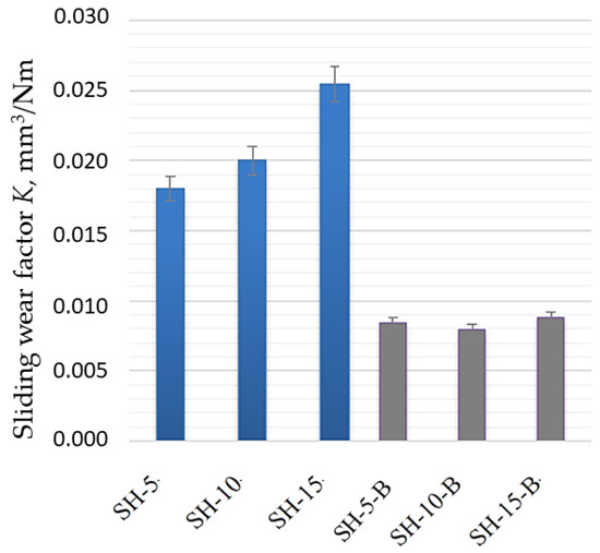
Figure 11.
Mean values of sliding wear factor for uncoated and TiBN coated samples.
No significant difference between the values of friction coefficient can be detected for uncoated samples with different Co content. When these results are compared with coated samples decrease in friction coefficient of approximately 0.1 was detected for all samples regardless of the substrate Co content. This is not the case with sliding wear factor. Significantly higher wear factor can be observed for uncoated samples. By comparing dry sliding wear factor for these uncoated substrates, higher factor values and volume loss were detected for samples with higher Co content, i.e., lower hardness values. A significant decrease in dry sliding wear was observed after coating for all types of substrates since harder surface layer results in less volume loss. The analysis of wear factors for coated samples suggests no significant differences regardless of the substrate Co content, which also confirms stable coating behaviour in dry sliding wear conditions.
The average friction coefficient of 0.2 obtained for all coated samples during dry sliding wear conditions is in accordance to results found in literature [37]. Low friction coefficient of TiBN layer can be attributed to two aspects of the specific coating structure and properties. One being specific hardness/Young’s modulus ratio (HV/E), and other arising from potential self-lubricating behavior of TiBN coating [38].
The HV/E ratio is associated with the resistance to plastic deformation which significantly impacts wear behavior. High HV/E ratio characteristic for TiBN coating systems has been shown to provide good support for energy absorption during deformation resulting with good tribological behavior [39,40]. The tribochemical mechanism of TiBN self-lubricating behavior has been investigated and attributed to the formation of the lubricious rutile layer at the sliding surfaces interface generated by specific environmental conditions, humidity in particular [41,42].
3.3. Results of the Single Point Turning Test
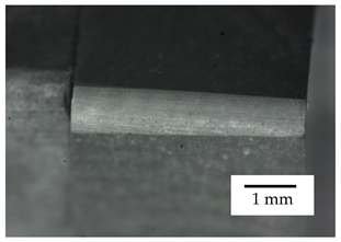
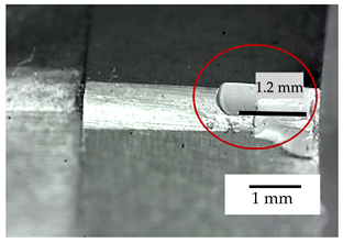
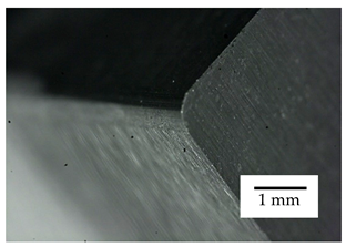
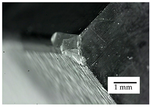
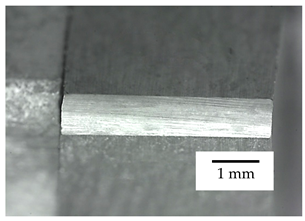
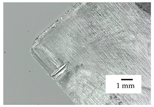
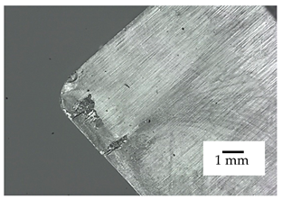
Table 11 presents the results for the sample of the SH-5 series. For this cemented carbide sample, the blade fracture occurred during tool/workpiece contact, which can be attributed to a large content of the fragile WC phase of high hardness that promoted brittle behavior, making this type of cemented carbide unsuitable for operation in real machining conditions.

Table 11.
Wear of sample SH-5 after turning test.
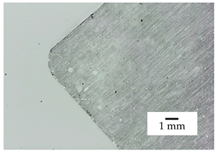
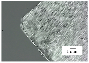
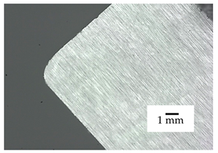
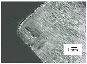
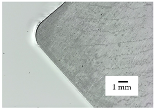
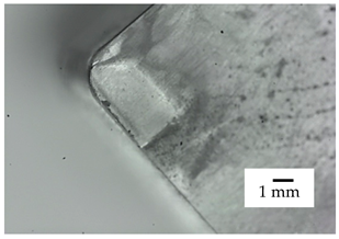
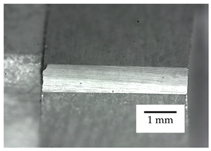
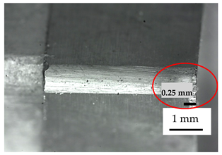
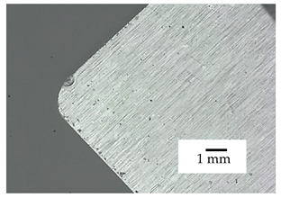
Table 12 gives a comparison of the wear pattern of the SH-15 sample and the commercial K10 cutting insert under the same machining modes. By comparing the SH-15 and K10 inserts, a similar tribological behavior was observed during turning.

Table 12.
Wear of sample SH-15 and reference K10 cutting insert after 15 min turning test.
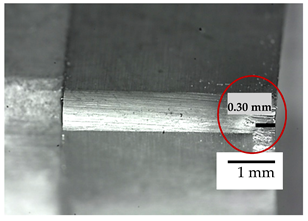
A small wear crater is visible on the rake face of the SH-15 cutting insert, while that on the commercial insert corresponds to the tool feed. The wear on the flank of the SH-15 insert was approximately 0.3 mm in length, which is the limit criterion of allowable wear. Commercially K10 insert did not meet the wear criteria after turning test due to trace size larger than 0.3 mm. Furthermore, a comparison of the inserts coated with TiBN coating was made, Table 13.

Table 13.
Wear of samples SH-10-B and SH-15-B after 15 min turning test.
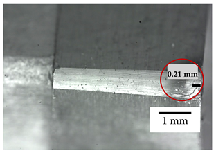
Samples SH-10-B and SH-15-B show an improvement in exploitation behavior. The cutting insert of the sample SH-10-B shows a wear trace of 0.25 mm, and for the sample SH-15-B, it is approximately 0.21 mm. Both coated cemented carbide samples withstood 15 min of processing with wear trace size at the flank less than 0.3 mm. This presents the additional confirmation that cemented carbide cutting tools should be coated with TiBN coating since they show better wear resistance than uncoated tools and even commercially available cutting inserts.
4. Conclusions
The conducted research presents analyses of completely novel type of tool material. In this article, the exploitation and wear behaviour of the three types of nanostructured cemented carbide tools with 5 wt% Co, 10 wt% Co and 15 wt% Co, produced by the sinter HIP process and additionally coated with a complex gradient TiBN coating, were investigated. This kind of coated nanostructured WC-Co material has not yet been presented or investigated as conventional machining, i.e., cutting tool material. In previous studies regarding TiBN coating of WC-Co substrates, PVD or CVD method was used, showing certain issues. The CVD method has proven to be unsuitable for nanostructured cemented carbide substrates since grain coarsening occurs, arising from high temperatures used during coating deposition. In addition, formation of etha carbides in the surface layers of the cemented carbides often occurred. Despite enabling coating at lower temperatures, PVD process requires continuous rotation of the substrates during coating by using expensive devices for sample positioning.
In this article, all the WC-Co substrate specific properties and nanoscale structure were preserved by utilizing the PACVD method which enabled lower temperatures during deposition and lower costs when compared to the PVD method. Material obtained in this study, therefore shows great potential as novel cutting tool material for which analysis of wear and exploitation behaviour in general cutting applications has not yet been investigated.
Based on the analysis of the properties and durability of developed substrate/coating systems characterized by erosion wear testing, sliding wear testing and single-point turning test, the following conclusions can be drawn from the conducted research:
- (i)
- Resistance to abrasive erosion, at a small angle of erodent particles impact, rises with the decrease of Co content in cemented carbides. In the case of impact erosion (at a higher angle of erodent incidence), the softest SH-15 sample with the highest Co binder content, showed the best resistance. This can be attributed to the positive effect of the Co binder on the toughness of the material, which enables more efficient damping of the erodent impact energy, preserving the brittle carbide phase from fracturing.
- (ii)
- Complex TiBN coating significantly improves erosion resistance, which is attributed to the damping effect of the coating to the substrate, relying on coating toughness being superior to that of the WC-Co substrate.
- (iii)
- The application of the TiBN coating via PACVD procedure, contributes both to the friction coefficient and dry sliding wear factor reduction. Variations of the friction coefficient for coated samples are attributed to the multilayered/gradient coating structure.
- (iv)
- The substrate Co content does not affect the magnitude of the friction coefficient both before and after coating but has a significant effect on the dry sliding wear factor. The harder cemented carbides with a higher WC phase content are characterized by a higher sliding wear resistance. Deposition of the TiBN coating resulted with the friction coefficient reduction to ~0.2 regardless of the Co binder content. Low friction coefficient of TiBN layer can be attributed to its specific hardness/Young’s modulus ratio (HV/E), and to self-lubricating behavior of TiBN coating arising from rutile formation on the interface surface during sliding.
- (v)
- The uncoated nanostructured SH-15 group cutting sample exhibited superior behavior in real-like operation compared to the commercial cutting K group material. However, the uncoated samples with a higher carbide content (95 wt% WC) were shown to be unsuitable for cutting applications due to excessive brittleness of the carbide phase.
- (vi)
- Further significant improvement in the operational behavior of the nanostructured tool was achieved by TiBN coating, which provided better durability of tool samples during machining at a speed of 200 m/min, cutting depth of 1 mm and an offset of 0.2 mm.
- (vii)
- The optimum substrate/coating system that showed improved wear resistance and superior behavior during real-life cutting conditions was the nanostructured WC-Co material with 15 wt.% Co, coated with multilayered TiBN coating.
All the obtained data confirmed the potential of expanding nanostructured cemented carbides application in the field of cutting tool materials.
Author Contributions
Conceptualization, M.Š.M., M.S. and D.Ć.; data curation, M.S.; formal analysis, M.Š.M. and T.A.F.; investigation, M.S.; methodology, D.Ć.; supervision, D.Ć.; writing—original draft, M.Š.M.; writing—review and editing, M.Š.M., D.Ć. All authors have read and agreed to the published version of the manuscript.
Funding
This research received no external funding.
Data Availability Statement
Sakoman, M. (2020). Development of PACVD coatings on nanostructured hardmetals; doctoral thesis; Repository of the Faculty of Mechanical Engineering and Naval Architecture, University of Zagreb; https://urn.nsk.hr/urn:nbn:hr:235:951787.
Acknowledgments
This work is supported in part by the Croatian Science Foundation under the Project Number UIP-2017-05-6538 Nanostructured hardmetals—New challenges for Powder Metallurgy.
Conflicts of Interest
The authors declare no conflict of interest.
References
- Rosa, M.M. Hardmetals. Comprehensive Hard Materials; Sarin, V.K., Mari, D., Nebel, C.E., Eds.; Elsevier: Amsterdam, The Netherlands, 2014; Volume 1, pp. 527–538. [Google Scholar]
- Rizzo, A.; Goel, S.; Grilli, M.L.; Iglesias, R.; Jaworska, L.; Lapkovskis, V.; Novak, P.; Postolnyi, B.O.; Valerini, D. The Critical Raw Materials in Cutting Tools for Machining Applications: A Review. Materials 2020, 13, 1377. [Google Scholar] [CrossRef]
- Alves, S.M.; Albano, W.; de Oliveira, A.J. Improvement of coating adhesion on cemented carbide tools by plasma etching. J. Braz. Soc. Mech. Sci. Eng. 2017, 39, 845–856. [Google Scholar] [CrossRef]
- Sheikh-Ahmad, J. On the wear of cemented carbide tools in the continuous and interrupted cutting of particleboard. In Proceedings of the 14th International Wood Machining Seminar, Paris, France, 12–19 September 1999. [Google Scholar]
- Bouzakis, K.D.; Skordaris, G.; Gerardis, S.; Katirtzoglou, G.; Makrimallakis, S.; Pappa, M.; Lili, E.; M’Saoubi, R. Ambient and elevated temperature properties of TiN, TiAlN and TiSiN PVD films and their impact on the cutting performance of coated carbide tools. Surf. Coat. Technol. 2009, 204, 1061–1065. [Google Scholar] [CrossRef]
- Neves, D.; Diniz, A.E.; Lima, M.S.F. Microstructural analyses and wear behavior of the cemented carbide tools after laser surface treatment and PVD coating. Appl. Surf. Sci. 2013, 282, 680–688. [Google Scholar] [CrossRef]
- Haubner, R.; Kalss, W. Diamond deposition on hardmetal substrates—Comparison of substrate pre-treatments and industrial applications. Int. J. Refract. Met. Hard Mater. 2010, 28, 475–483. [Google Scholar] [CrossRef]
- Xu, F.; Xu, J.H.; Yuen, M.F.; Zheng, L.; Lu, W.Z.; Zuo, D.W. Adhesion improvement of diamond coatings on cemented carbide with high cobalt content using PVD interlayer. Diam. Relat. Mater. 2013, 34, 70–75. [Google Scholar] [CrossRef]
- Kathrein, M.; Heiss, M.; Rofner, R.; Schleinkofer, U.; Schintlmeister, W.; Schatte, J.; Mitterer, C. Wear protection in cutting tool applications by PACVD (Ti,Al)N and Al2O3 coatings. Powder metallurgical high-performance materials. In Proceedings of the 15th International PLANSEE Seminar, Loeben, Austria, 30 May–3 June 2001. [Google Scholar]
- Sousa, V.F.C.; Silva, F.J.G. Recent Advances on Coated Milling Tool Technology—A Comprehensive Review. Coatings 2020, 10, 235. [Google Scholar]
- Tillmann, W.; Grisales, D.; Stangier, D.; Butzke, T. Tribomechanical Behaviour of TiAlN and CrAlN Coatings Deposited onto AISI H11 with Different Pre-Treatments. Coatings 2019, 9, 519. [Google Scholar] [CrossRef]
- Abadias, G. Stress in thin films and coatings: Current status, challenges, and prospects featured. J. Vac. Sci. Technol. 2018, 36, 020801. [Google Scholar] [CrossRef]
- Mitterer, C.; Holler, F.; Reitberger, D.; Badisch, E.; Stoiber, M.; Lugmair, C.; Nöbauer, R.; Müller, T.H.; Kullmer, R. Industrial applications of PACVD hard coatings. Surf. Coat. Technol. 2003, 163, 716–722. [Google Scholar] [CrossRef]
- Polcar, T.; Kubart, T.; Novak, R.; Kopecky, L.; Široký, P. Comparison of tribological behaviour of TiN, TiCN and CrN at elevated temperatures. Surf. Coat. Technol. 2005, 193, 192–199. [Google Scholar] [CrossRef]
- Heim, D.; Holler, F.; Mitterer, C. Hard coatings produced by PACVD applied to aluminium die casting. Surf. Coat. Technol. 1999, 116, 530–536. [Google Scholar] [CrossRef]
- Nordin, M.; Larsson, M.; Hogmark, S. Mechanical and tribological properties of multilayered PVD TiN/CrN, TiN/MoN, TiN/NbN and TiN/TaN coatings on cemented carbide. Surf. Coat. Technol. 1998, 106, 234–241. [Google Scholar]
- Bunshah, R.F. Handbook of Hard Coatings. Tribol. Int. 2001, 34, 203–205. [Google Scholar]
- Kovačić, S. Influence of Nitriding and Coatings on Properties of Hot Work Tool Steels. Ph.D. Thesis, University of Zagreb, Zagreb, Croatia, 2015. [Google Scholar]
- Holmberg, K. Coatings Tribology. Igarss 2014, 28, 1–5. [Google Scholar]
- Gyula, B.; Enikő, B. Some Aspects of Damage Management for Cutting Tool Materials. Műszaki Tud. Közlemények. 2020, 12, 15–22. [Google Scholar]
- Chermant, J.L.; Osterstck, F. Fracture toughness and fracture of WC-Co composites. J. Mater. Sci. 1976, 11, 1939–1951. [Google Scholar] [CrossRef]
- Warren, R.; Johannesson, B. The fracture toughness of hard metals. Int. J. Refract. Hard Met. 1984, 3, 187–191. [Google Scholar]
- Schubert, W.D.; Bock, A.; Lux, B. General aspects and limits of conventional ultrafine WC powder manufacture and hardmetal production. Int. J. Refract. Hard Met. 1995, 13, 281–296. [Google Scholar] [CrossRef]
- Jia, K. The Effect of Fine Microstructure on the Wear and Relevant Mechanical Properties of Cemented Carbide. Ph.D. Thesis, Stevens Institute of Technology, Hoboken, NJ, USA, 1996. [Google Scholar]
- Rabinowicz, E. Penetration hardness and toughness indicators of wear resistance. Mater. Sci. 1987, 22, 197–201. [Google Scholar]
- Larsen-Basse, J. Binder extrusion in sliding wear of WC-Co Alloys. Wear 1985, 105, 247–256. [Google Scholar] [CrossRef]
- Larsen-Basse, J. Effect of composition, microstructure, and service conditions on the wear of cemented carbides. JOM 1983, 35, 35–42. [Google Scholar] [CrossRef]
- Exner, H.E.; Gurland, J. A review of parameters influencing some mechanical properties of tungsten carbide cobalt alloys. Powder Met. 1970, 13, 13–31. [Google Scholar] [CrossRef]
- Lee, H.C.; Gurland, J. Hardness and deformation of cemented tungsten carbide. Mater. Sci. Eng. 1978, 33, 125–133. [Google Scholar] [CrossRef]
- Exner, H.E. Qualitative and quantitative interpretation of microstructures in cemented carbides. In Science of Hard Materials; Springer: Boston, MA, USA, 1983; pp. 233–262. [Google Scholar]
- O’Quigley, D.F.G.; Luyckx, S.; James, M.N. An empirical ranking of a wide range of WC-Co grades in terms of their abrasion resistance measured by the ASTM standard B 611-85 test. Int. J. Refract. Hard Met. 1997, 15, 73–79. [Google Scholar] [CrossRef]
- Antonov, M.; Veinthal, R.; Yung, D.L.; Katušin, D.; Hussainova, I. Mapping of impact-abrasive wear performance of WC–Co cemented carbides. Wear 2015, 332, 971–978. [Google Scholar] [CrossRef]
- Zhou, X.; Wang, K.; Li, C.; Wang, Q.; Wu, S.; Liu, J. Effect of ultrafine gradient cemented carbides substrate on the performance of coating tools for titanium alloy high speed cutting. Int. J. Refract. Hard Met. 2019, 84, 105024. [Google Scholar] [CrossRef]
- Fang, S.; Marro, F.G.; Salan, N.; Cruz, M.; Colominas, C.; Bähre, D.; Llanes, L. Surface integrity assessment of laser treated and subsequently coated cemented carbides. Int. J. Refract. Hard Met. 2019, 83, 104982. [Google Scholar]
- Sakoman, M.; Ćorić, D.; Šnajdar Musa, M. Plasma-assisted chemical vapor deposition of TiBN coatings on nanostructured cemented WC-Co. Metals 2020, 10, 1680. [Google Scholar] [CrossRef]
- International Organization for Standardization. Tool-Life Testing with Single-Point Turning Tools; ISO: Geneva, Switzerland, 1993. [Google Scholar]
- Asempah, I.; Xu, J.; Yu, L.; Ju, H.; Wu, F.; Luo, H. Microstructure, mechanical and tribological properties of magnetron sputtered Ti-B-N films. Surf. Eng. 2019, 35, 1–9. [Google Scholar] [CrossRef]
- Dreiling, I.; Raisch, C.; Glaser, J.; Stiens, D.; Chassé, T. Temperature dependent tribooxidation of Ti–B–N coatings studied by Raman spectroscopy. Wear 2012, 288, 62–71. [Google Scholar] [CrossRef]
- Matthews, A.; Franklin, S.; Holmberg, K. Tribological coatings: Contact mechanisms and se-lection. J. Phys. D 2007, 40, 5463–5475. [Google Scholar] [CrossRef]
- Erdemir, A. A crystal chemical approach to the formulation of self-lubricating nanocom-posite coatings. Surf. Coat. Technol. 2005, 200, 1792–1796. [Google Scholar] [CrossRef]
- Badisch, E.; Mitterer, C.; Mayrhofer, P.H.; Mori, G.; Bakker, R.J.; Brenner, J.; Störi, H. Characterization of tribo-layers on self-lubricating plasma-assisted chemical-vapor-deposited TiN coatings. Thin Solid Films 2004, 460, 125. [Google Scholar] [CrossRef]
- Kutschej, K.; Mayerhofer, P.H.; Kathrein, M.; Polcik, P.; Tessadri, R.; Mitterer, C. Structure, mechanical and tribological properties of sputtered Ti1–xAlxN coatings with 0.5≤x≤0.75. Surf. Coat. Technol. 2005, 200, 2358. [Google Scholar] [CrossRef]
Publisher’s Note: MDPI stays neutral with regard to jurisdictional claims in published maps and institutional affiliations. |
© 2021 by the authors. Licensee MDPI, Basel, Switzerland. This article is an open access article distributed under the terms and conditions of the Creative Commons Attribution (CC BY) license (http://creativecommons.org/licenses/by/4.0/).


