Abstract
The plasma-assisted chemical vapor deposition (PACVD) technique has shown many advantages in applications, where thin coatings with superior wear properties are demanded, especially for geometrically complex parts. In this study, multilayered gradient TiBN coatings that were deposited on nanostructured cemented carbides by the PACVD method were investigated. Nanostructured samples of cemented carbides with the addition of 5 and 15 wt.% Co were sintered by the hot isostatic pressing, sinter-HIP technique. Surface preparation was conducted on samples in order to enable maximum coating adhesion. Tests that were conducted on produced samples aimed to investigate the mechanical and physical properties of coated samples. These tests included nanoindentation, surface layer characterization, and coating adhesion evaluation while using the Rockwell and scratch test. The obtained results confirmed that the PACVD process can be utilized for applying thin hard coatings to nanostructured cemented carbides that are produced by the sinter HIP process, resulting in a base material/ coating system that exhibits excellent physical and mechanical properties. The results presented in this paper give a valuable contribution to the research of TiBN coating systems and their potential for application under heavy wear conditions.
1. Introduction
Cemented carbides are among the most researched and most developed representatives of materials that were obtained by powder metallurgy. Their main constituents, hard and brittle tungsten carbides (WC), and the softer and tougher cobalt (Co) matrix, are key for their specific properties. The field of cemented carbides application is continuously expanding due to high market demands and their favorable properties, such as: high hardness, wear resistance, high flexural and compressive strength, high modulus of elasticity, resistance to elevated temperatures, high corrosion resistance, etc. The development of cemented carbides in recent years is based on the application of ultrafine and nanoparticle powders that enable significant material properties improvement especially for applications such as cutting [1]. Requirements for increasing cutting speeds in order to achieve a sustainable level of production are continuously increasing [2]. Therefore, the materials are required to have high-temperature dimensional stability and reduced friction coefficient [3], high strength, and high hardness [4]. The most common wear mechanisms that affect cutting tool lifetime are abrasion and adhesion wear [4], delamination wear [5], and wear caused by tools and workpiece chemical incompatibility, which includes diffusion wear, wear that is caused by dissolution, and electrochemical wear. Cemented carbide has proven to be the optimal material for cutting tools in terms of properties, price, and durability [6].
Numerous studies [7] (p.9), [8] (p.3), have proven that the use of nano-sized cemented carbides results in relatively high flexural strength and fracture toughness, while also showing high hardness values; therefore, contributing to the crack propagation resistance [9]. All of the mentioned advantages of nanostructured cemented carbides can only be fully utilized if the carbide grain remains on the nanoscale after the consolidation process [10]. Grain growth, which inevitably occurs in the sintering process, can be reduced by adding grain growth inhibitors (GGIs), such as carbides of vanadium, chromium, tantalum, and niobium [11], and by sintering time and temperature optimization. Vanadium carbide (VC) has a positive effect on the hardness at elevated temperatures, while chromium carbide (Cr3C2) increases toughness. The combination of VC–Cr3C2 (TaC) yields an optimum ratio of hardness and toughness [12]. Earlier studies have also shown that Co binder particles do not have to be nano-sized, since their primary function is filling the pores between carbides and enabling sintering at lower temperatures with shorter bonding times. This improves the microstructural characteristics of the sintered product [13], indirectly preventing grain growth [14].
By surface processing (modification and/or coating), it is possible to form a surface layer/base material (substrate) system with properties that can meet the modern expectations that are placed on these materials at an acceptable production cost.
Research of nanostructured cemented carbides with TiN, TiCN, TiBN, or TiB2 coatings is a very interesting research area, due to specific, so far, unsolved issues regarding high reactivity of nano-sized cemented carbides, both in the sintering and coating phase. High-temperature coating processes, such as chemical vapor deposition (CVD), can cause microstructural defects in the surface layers, dependent on the Co content [15]. On the one hand, eta (η)-phase, occurring at temperatures that are below 800 °C in the form of metal carbides (M6C), and unbound carbon are the most common microstructural defects often significantly deteriorating fracture toughness and strength as well as the adhesiveness of the applied coating [16]. On the other hand, vapor phase physical coating (PVD) processes that were carried out at lower temperatures result in thicker coatings, ultimately reducing their stability and adhesiveness [17] while making the coating process more complex. In PVD procedures, the coating is directly applied to the sample surface (line of sight), so there is a need for sample rotation. Titanium nitride (TiN), titanium carbide (TiC), titanium carbonitride (TiCN), titanium boron nitride (TiBN), and alumina (Al2O3) are commonly used coatings available on the market. Recent studies have indicated the need for the development of complex architecture coatings, primarily of multilayer and gradient type, which were shown to have a significant effect on heat dissipation during tool heating [18]. Multilayer gradient coatings are usually formed through three layers. The first is a thin layer, the main role of which is adhesion to the substrate. The middle layer gradually changes from the adhesion layer to the surface, creating a bond between the layers of lower and higher hardness. Besides increasing the wear resistance, the role of the top layer is to achieve high-temperature coating stability [19,20]. Plasma-assisted chemical vapor deposition (PACVD) is a process that combines most of the advantages of CVD coating with the PVD coating technique, which can result in coating formation at significantly lower temperatures. Nevertheless, the full range of its possibilities is still insufficiently explored.
This article presents an investigation of nanostructured cemented carbides and the possibility of applying the PACVD as coating process of hard thin coatings and the development of a new, innovative coating with improved properties.
For the purpose of investigating properties, microstructure and quality of the substrate/coating interface tests were performed on both uncoated and coated samples. The characterization of the uncoated substrate cemented carbide material included density measurement, specific magnetization saturation test, hardness and fracture toughness determination, modulus of elasticity determination by nanoindentation method, microstructural analysis aimed at investigating the presence of the porosity, structural constituents, and possible irregularities. Microstructure analysis, surface roughness, coating adhesion, thickness, and microhardness were tested in order to give insight into complex multilayered coating properties, obtained by the described PACVD process.
For the actual validation of the superiority of this material in applications, such as cutting, it is necessary to conduct additional research in the form of abrasion and erosion resistance testing, dry sliding wear, and friction factor testing, along with exploitation tests in real turning conditions. Because of the demanding implementation and complexity of such testing, that type of testing is not included in this paper, since the research presented here is exclusively focused on the process of obtaining valuable data on the basic characteristics of both substrate and coated cemented carbide, and not the final product such as a removable cutting blade. Because data on this type of PACVD coated nanostructured WC-Co material have not been found in the recent literature, the key interest of this research was to create a basis for an overall understanding of material capability in order to answer all of the demands opposed on future products.
2. Materials and Methods
2.1. Powder Mixing and Sintering
Through the application of sinter-HIP process, samples of nanostructured cemented carbide were consolidated while using mixtures of nano powder of tungsten carbide (WC), manufacturer: H.C. Starck, Germany and cobalt powder (Co), manufacturer: Umicore, Canada with that characteristics shown in Table 1.

Table 1.
Starting powders.
The specific surface area of powders was measured by the BET (Brunauer, Emmett, and Teller) method.
Vanadium carbide (VC) and chromium carbide (Cr2C3) were also added as grain growth inhibitors (GGIs). Two different mixtures of 5 wt.% and 15 wt.% Co were produced. Table 2 presents the mixture compositions.

Table 2.
Mixtures compositions.
To obtain insight into the physical properties of powders, a microstructural analysis was conducted while using field emission scanning electron microscope (FESEM, Tescan MIRA//LMU, Brno-Kohoutovice; Czech Republic) on WC powder, as in Figure 1a, and scanning electron microscope (SEM, Tescan Vega TS 5136 MM, Brno-Kohoutovice, Czech Republic) used on Co powder, as in Figure 1b.
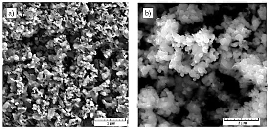
Figure 1.
Micrographs of starting powders: (a) field emission scanning electron microscope (FESEM) micrograph of tungsten carbide (WC) DN 4-0; (b) scanning electron microscope (SEM) micrograph of Co powder [21].
Particles of WC powder tend to agglomerate and available sieving techniques were unable to isolate individual particles of powder, as visible from Figure 1a. Nevertheless, microstructure analysis shows powder particles marked WC DN 4-0 to be of rounded three-dimensional shape, indicating powder production by atomization or chemical decomposition process. The Co particles of uniform grain size are of three-dimensional spherical shape, which indicates production by the atomization process.
After mixing and milling of WC and Co powders in a horizontal ball mill (Netzsch FMT, Selb, Germany), 2 wt.% of plasticizer in the form of paraffin was added to the powder mixture in order to assure good formability of the raw material during the compaction process. Sieving was carried out for the purpose of acquiring the desired powder flow properties. The last stage of sample compaction included hot isostatic pressing, along with sintering by the sinter-HIP process. In order to minimize material cost, the geometry of a commercially available cutting tool (from the Widia Products Group catalog: code SNGN120408) shown in Figure 2 was chosen for the initial shape of the specimens, so that the same specimens could later be used for future in-service turning tests of cutting tools in realistic machining conditions and, therefore, make a comparison with commercially available cutting inserts on the market possible.
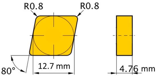
Figure 2.
Sample geometry.
Pre-sintering and sintering were carried out in an FCT Anlagenbau GmbH furnace, type: FPW 280 / 600-3-2200-100-PS (Sonneberg, Germany). After the pre-sintering, and prior to sintering itself, the sample weight was determined in order to ensure the complete removal of the binder. The GGIs content and carbon content of the sintering atmosphere was individually adjusted for each powder mixture in order to avoid the formation of an unwanted η-phase and unbound carbon. Carbon content that originates from starting powder mixtures, rather than an addition to the sintering atmosphere, was 0.275 wt.% for SH-5 mixture and 0.150 wt.% C for SH-15 mixture. Binder removal during the pre-sintering phase was performed, as shown in Figure 3.
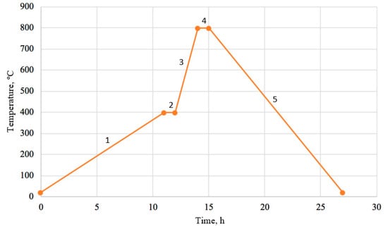
Figure 3.
Scheme of pre-sintering process: 1—Heating with rate of 1 K/min. in H2 up to 400 °C; 2—Holding at 400 °C for 60 min. in the Ar atmosphere; 3—Heating with rate of 5 K/min. in Ar up to 800 °C; 4—Holding at 800 °C for 60 min.; and, 5—Cooling to the room temperature.
The selected heating rates ensured that the sample was completely warmed up, while the presence of argon prevented the influence of the external atmosphere on the microstructural changes. Sample sintering was carried out by the sinter-HIP process, which included vacuum sintering, followed by one cycle of hot isostatic pressing in the second phase of sintering, as in Figure 4.
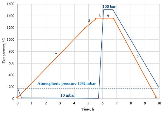
Figure 4.
Scheme of sinter-HIP process: 1—Heating with rate of 5 K/min. up to 1200 °C at 10 mbar Ar pressure; 2—Heating with rate of 10 K/min. from 1200 °C to 1350 °C at 10 mbar Ar pressure; 3—Holding at 1350 °C for 30 min.; 4—Increasing of Ar pressure up to 100 bar and holding at 1350 °C for 45 min.; and, 5—Reducing pressure, degassing Ar and cooling to the room temperature.
2.2. Coating Process
The coating process was performed in a PACVD system that was manufactured by Rübig (RÜBIG GmbH & Co KG, Marchtrenk, Austria), type: PC 70/90, Figure 5. The samples were positioned in the coating cartridge at the same height and equidistant from the center of the chamber in order to achieve the same conditions allowing for the formation of identical layers on samples. The surface of some substrates was polished prior to coating to allow for the possibility of later testing and coating analysis. A three-step polishing process was performed on samples: (1) 9 μm particle size diamond paste at a speed of 150 rpm and force of 210 N for 5 min.; (2) 6 μm diamond paste for 10 min. with equal force; and, (3) 3 μm particle size diamond paste at a force of 150 N for 8 min. The samples were also ultrasonically treated by immersion in a bath of 99.8% isopropyl alcohol for 5 min. and dried. Prior to coating, the samples were cleaned by the ionic method for 2.5 h at 490 to 530 °C. The cleaning was carried out in a standard gas mixture of 15% N2, 5 % Ar, and 85% H2 with a voltage of 540 V and plasma power ranging from 900 to 1800 W at a pressure of 2 bar. The deposition of a coating of complex architecture built of TiN and TiB2 layers was carried out on four samples from each substrate with the parameters that are shown in Table 3.
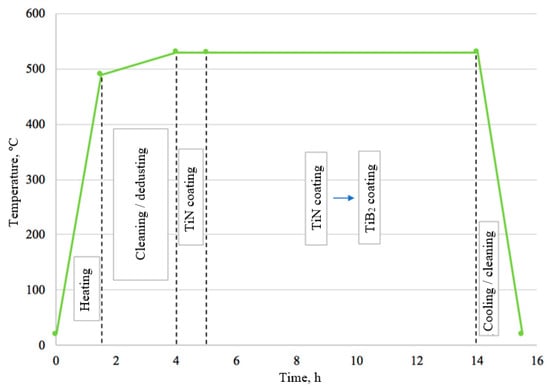
Figure 5.
Scheme of plasma-assisted chemical vapor deposition (PACVD) coating.

Table 3.
The characteristics of titanium boron nitride (TiBN) coating by PACVD process.
In order to achieve a gradual transition between layers, the flow of N2 was gradually reduced (step by step) to release BCl3, a precursor in charge of releasing boron. TiN as the backing layer was followed by TiB2 and their 30 alterations, and the upper final layer was TiB2. TiCl4 was used as a titanium precursor.
2.3. Characterization Methods
2.3.1. Base Material
The density of sintered samples was determined by the comparative method by weighing the samples in both air and distilled water according to the standard HRN EN ISO 3369: 2011 [22]. The density measuring was performed at a temperature of 23.6 °C on a density determination kit that was manufactured by Mettler Toledo, type MS DNY 43 (Giessen, Germany). Three measured densities per sample were compared with the theoretical density ρth, which was calculated according to the proportions of individual components (xi) in the initial mixtures and their densities (ρi), as follows from Equation (1):
Magnetic measurements that generally allow for the detection of very subtle metallurgic events were conducted in order to determine specific saturation magnetization (σs) of material. This parameter characterizes the ferromagnetic Co phase, and it is independent of the structure and shape of the sample. When a ferromagnetic compound is positioned in a magnetic field, it becomes magnetized. The value of its magnetization increases with the field and then reaches a maximum. The specific saturation magnetization is the ratio of the magnetic moment maximum to the mass of the material. Magnetic measurements were aimed at detecting the presence of eta phase and unbound carbon. These measurements were performed on a sigmameter D6025 (Setaram Instrumentation, Caluire et Cuire, France) in accordance with DIN ISO 3326: 2013 [23]. Approximate values of WC grain size were obtained by obtaining the coercivity measurements on a Foerster device (type 1.096).
For the microstructure analysis and determination of mechanical properties, sintered samples were metallographically prepared according to the recommendations for this type of material. Surface roughness measurements were performed before and after metallographic preparation on an unprepared (as-sintered) surface and on polished surface with a polishing procedure that is equal to the one used for substrate preparation prior to coating. The measurements were carried out on a three-dimensional (3D) micro-coordinate measuring device InfiniteFocus XL200 G5 manufactured by Bruker Alicon, Mannheim, Germany.
Hardness measurements of cemented carbide substrates were performed on the reference hardness tester, manufactured by Indentec (Brierley Hill, UK), type: 5030 TKV. The measurements were carried out by the Vickers method with a load of 30 kgf (294.2 N), which corresponds to the method HV30, in accordance with the requirements of the standard HRN EN ISO 6507-1: 2018 [24].
The Palmqvist indentation method was applied for determining fracture toughness, based on measuring the length of cracks l1, l2, l3, l4 extending from the corners of the Vickers indentation. The values of fracture toughness according to Palmqvist (WK) were determined in accordance with ISO 28079: 2009 [25] and Equations (2) and (3):
where: WG—Palmqvist toughness, N/mm, which is equivalent to J/m2, P—applied load, N; T—total crack length, T = l1 + l2 + l3 + l4 mm; WK—Palmqvist fracture toughness, MN/m3/2, which is equivalent to MPa·m1/2; A—is an empirical constant with a value of 0.0028; and, H—is the hardness in N/mm2 at a load of 30 kgf (294.2 N).
Because nanostructured cemented carbides with very homogeneous microstructure and very small grain size were investigated, the nanoindentation was used to probe the mechanical response of the consolidated samples. The measurements were carried out in order to determine the Young modulus of elasticity (E). A new Berkovich diamond indenter in the form of a triangular pyramid was used on Shimadzu hardness tester, type DUH 211S. During nanoindentation, with the maximum load of 1500 mN, in accordance with the standard HRN EN ISO 14577-1: 2015 [26], load and displacement were continuously monitored. A force of 1500 mN was chosen in order to avoid undesirable effects, such as sink-in or pile-up, and to ensure an indenter penetration depth greater than 1/20 of the roughness parameter Ra. The maximum load (Pmax), the maximum displacement (hmax), the final depth (hf), and the elastic unloading stiffness (S) were determined, as shown in Figure 6.
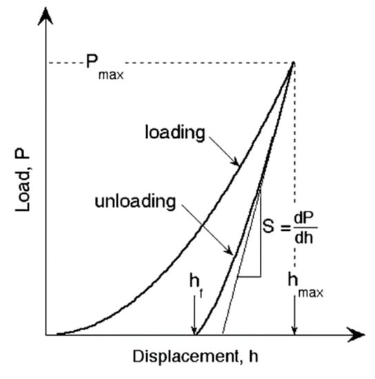
Figure 6.
Schematic load-displacement diagram [27].
Elastic unloading stiffness or contact stiffness (S) is defined as the slope of the initial stage of the unloading curve and it is calculated according to Equation (4) [27]:
In order to calculate reduced (effective) elastic modulus (Er), the contact depth (hc), as a function of final displacement hf and indenter’s tip geometry, was calculated while using the following expression [27]:
where ε is a constant dependent on indenter geometry that, for a Berkovich indenter, has a value of 0.75.
From contact stiffness, the reduced elastic modulus Er is obtained using Oliver and Pharr equation [27]:
where hc is the contact depth and A(hc) is the projected contact indentation area determined as function of contact depth hc.
A reduced modulus of elasticity (Er) can also be described as a function of Young’s modulus, E and Poisson’s ratio, of both indenter and testing sample material, as shown in following expression [27,28]:
where: νi—Poisson’s ratio of indenter; Ei—indenter modulus of elasticity, N/mm2; νs—Poisson’s ratio of sample; Es—sample modulus of elasticity, N/mm2.
Substrate surface analysis was performed in order to determine porosity and unbound carbon presence. The polished surface of the consolidated samples was observed at 100× and 200× magnification while using Olympus (Zagreb, Croatia) GX51F-5M optical microscope. The amounts of porosity and unbound carbon were determined by comparing the polished surface of the sample with the photomicrographs that were specified in ISO 4505:2011 [29].
Analysis of the microstructure by scanning electron microscopy was performed to determine the microstructural homogeneity, detect structural constituents, their size, and possible irregularities, such as carbide clustering or abnormal WC grain growth. Because carbide clusters tend to form at higher temperatures, these defects can be generated by using inappropriate sintering parameters. Abnormal grain growth can also occur due to pronounced diffusion during prolonged holding at sintering temperature or if the chosen temperature is too high. The sample surface was etched for the purpose of microstructure analysis. Etching was conducted for 5 min. with Murakami solution. Electron microscopy was carried out on a field emission scanning electron microscope (FESEM, Ultra 55, Carl Zeiss AG (Munich, Germany) at Fraunhofer IKTS. The WC grain size was determined by the line method in accordance with the HRN EN ISO 4499-2:2008 standard [30]. The quantitative analysis consisted of processing the micrograph that was obtained under 20,000× magnification with the drawn 10 parallel lines, while using the software package Image J. The mean value of WC grain size (dWC) was calculated according to Equation (8):
where li is total length of sectioned grains nz.
The X-ray diffraction (XRD) method was used to investigate the content of phase constituents (Co, WC). This analysis was performed on Bruker AXS GmbH (Karlsruhe, Germany) X-ray diffractometer, type D8 Advance
2.3.2. Coating
The characterization of the obtained coating surface layers was performed by microstructural analysis while using light and electron microscopy, surface roughness determination, coating adhesion testing by scratch test and Rockwell C indenter indentation method, coating thickness measurement by calotest method, and microhardness testing. The surface roughness examination after the coating is an indirect method of coating quality control, since uneven growth indicates an inadequate coating process. Roughness measurements were performed on a Form Talysurf Series 2 device that was manufactured by Taylor-Hobson GmbH. Three measurements per sample were made.
The thickness of the coating is one of the most influential factors that characterizes the wear behavior of the coating and affects its adhesiveness. The thickness was determined on TRIBOtechnik Calotester in accordance with EN 1071-2: 2003. The steel ball Ø 25 mm was rotating with 500 rpm for 45 s. The coating thickness (e) was determined according to the equation:
where: D—outer diameter of impression, μm; d—inner diameter of impression, μm; and, R—radius of the ball, μm.
X-ray diffraction was also performed on coated samples to determine the microstructural phases and crystallographic structures of the coated layer. The XRD6000 diffractometer (Shimadzu Corporation, Tokyo, Japan) with CuKα radiation was used. The acceleration voltage of 40 kV and a current of 30 mA, in the 2θ range of 2 to 120° with a step of 0.02° and retention time of 0.6 s were applied.
The microhardness and elasticity modulus of the coating were determined by the indentation method on a Fischerscope microhardness tester (Helmut Fischer GmbH, Sindelfingen, Germany). Five indentations were made on each sample while using a Berkovich indenter with an indentation force of 50 mN. This force was chosen, so that the maximum indentation depth hmax is 1/10 of the coating thickness and higher than 1/20 of roughness parameter Ra.
The coating adhesion, being one of the most important properties in the wear protection, was tested by two methods: Rockwell indentation method, according to EN 1071-8: 2004 standard and scratch test in accordance with HRN EN 1071-3: 2008 standard. The standard EN 1071-8 refers to the Rockwell C method, in which a diamond cone is indented in the surface of the sample with the load of 1471 N, which can result in coating delamination or cracking.
The Rockwell test was carried out on VEB Werkstoffprüfmaschinen hardness tester. The indentations were analyzed on an Olympus GX51F-5 optical microscope. The scratch test was performed by linearly increasing the force (up to the maximum value of 50 N) acting on the Rockwell diamond indenter, which is simultaneously moving along the sample, as in Figure 7.
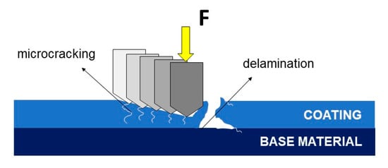
Figure 7.
Coating adhesion failure during scratch test.
Induced surface stresses result in the occurrence of one or more coating delaminations, crack initiation and propagation, and, ultimately, cracking. Accordingly, the critical loads are defined, as follows: Lc1—the appearance of the first cracks in the coating; Lc2—occurrence of coating delamination; and, Lc3—the appearance of complete coating separation and its penetration. The scratch test was carried out on a Macro Scratch Tester that was manufactured by Revetest CSM Instruments SA, France. The test was performed with three repetitions per sample.
3. Results and Discussion
3.1. Base Material
The density of sintered cemented carbides dependent on the content and density of constituents: WC, Co, and grain growth inhibitors, was determined. Table 4 shows the bulk density values of individual mixture constituents provided by the manufacturer.

Table 4.
Starting powders bulk densities.
The theoretical density ρth was calculated in accordance with component contents and densities. By comparing the theoretical and measured density, the degree of porosity of the sintered sample was determined, as shown in Table 5.

Table 5.
Sintered samples density.
The obtained post sintering density values indicate the formation of non-porous structures, since density values correlate to the theoretical values. In addition, in the case of the η-phase presence, it is also possible to measure densities higher than theoretical density since W6Co6C or W3Co3C possess higher densities than WC and Co constituents. Table 6 presents the results of magnetic and coercivity properties testing.

Table 6.
Magnetic and coercivity characteristics.
Magnetic properties analysis showed a specific saturation magnetization of 7.97 µTm³/kg for samples with 5 wt.% Co and 22.10 µTm³/kg for those with 15 wt.% Co. These results indicate the proper adjustment of the atmosphere during sintering, thus preventing microstructural defects, such as η-phase or unbound carbon formations, as in Figure 8.
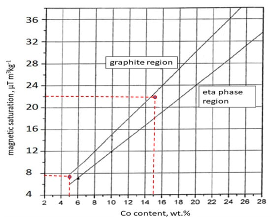
Figure 8.
Influence of magnetic saturation and Co content on the appearance of graphite and eta phase in quality control of cemented carbides [31].
The analysis of coercive properties of the substrate was performed for the purpose of indirect confirmation of nano grain size after sintering. The average value of the coercive force was 51.81 kA/m for the sample with 5wt.% Co and 37.23 kA/m for the sample with 15 wt.% Co. Although the results of this method cannot be taken with absolute certainty, they indicate the nano WC grain size achieved by the proper selection of VC and Cr2C3 GGIs and their content adjusted to the WC and Co powder content in the mixture, as in Figure 9.
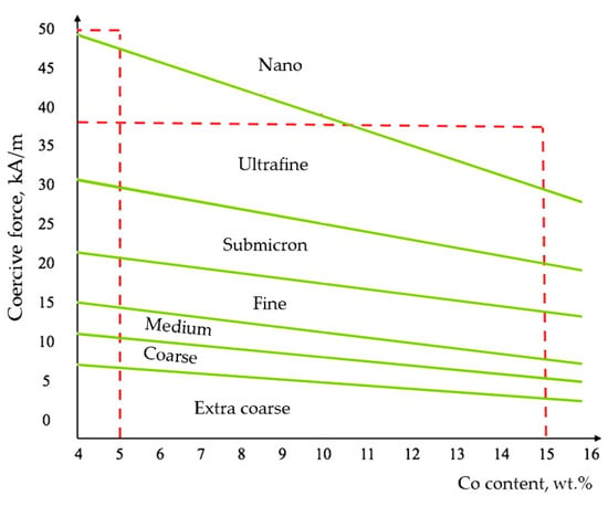
Figure 9.
Influence of coercive force and Co content on the WC grain size in quality control of cemented carbides [32].
Surface roughness parameters Ra and Rz were measured on sintered samples before and after metallographic preparation, as in Table 7. Figure 10 shows the topography of 1 mm × 1 mm surface area after polishing. The recorded profiles were filtered while using a Gaussian filter with a cut-off value of 0.8 mm for Ra results from 0.124 um to 0.194 μm and a cut-off value of 0.25 mm for Ra of 0.069 μm.

Table 7.
Surface roughness parameters of substrates.
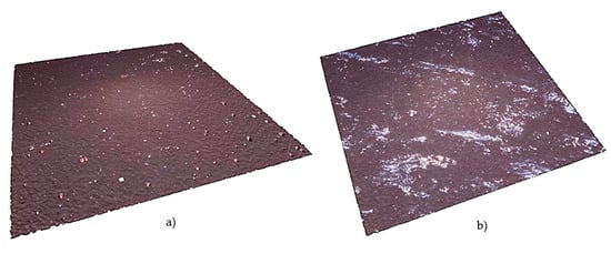
Figure 10.
Surface topography of the substrates: (a) SH-5; (b) SH-15.
When comparing these images as well as roughness parameters values, it is evident that a decrease in the Co content correlates with a roughness increase, which is associated with a higher content of harder carbide phase and difficult metallographic preparation.
Analysis of the measured hardness (mean values of nine measurements) of the samples SH-5 and SH-15 indicates the formation of very hard metal-ceramic composites, as in Table 8. The results show a decrease in hardness with an increase in the content of the softer Co phase.

Table 8.
Hardness and fracture toughness of substrate.
The measured hardness values show very little scatter, which indirectly implies the formation of a homogeneous microstructure. When comparing the hardness values with the literature data [33] (pp. 43, 46), (for a given Co content) it can be seen that they are similar, indirectly confirming an extremely small WC grain size in the range from ultrafine to nanoscale. As expected, the fracture toughness decreases with increasing content of the harder carbide phase, and its change is inversely proportional to hardness. Figure 11 presents the characteristic cracks emanating from the four corners of a Vickers indentation.
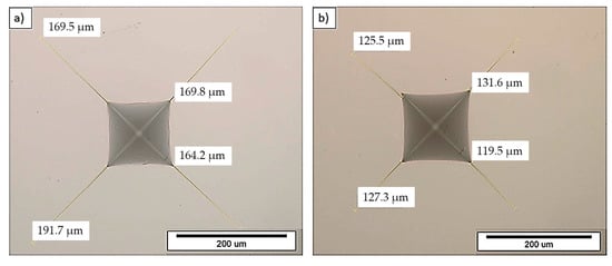
Figure 11.
Vickers indentation and cracks on the substrate: (a) SH-5; (b) SH-15.
The fracture toughness results also correspond to the literature data [34] (p.3) for nanostructured cemented carbides with similar Co content.
Figure 12 and Figure 13 refer to the characteristic force-displacement curves that were obtained by nanoindentation measurements, by which the modulus of elasticity of the sintered samples was determined.
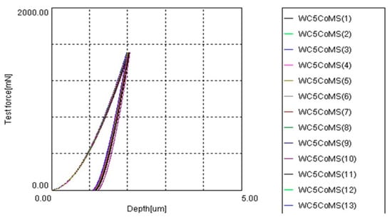
Figure 12.
The force-indentation depth curves of the substrate SH-5.
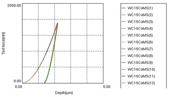
Figure 13.
The force-indentation depth curves of substrate SH-15.
Analysis of the measured hardness and fracture toughness of sintered samples SH-5 and SH-15 indicates the formation of very hard metal-ceramic composites, the hardness of which by 5% Co is as much as 2267.5 HV30 and 1781.2 HV30 for the one with 15% Co. When comparing the hardness values of tested samples with literature data for commercially available cutting materials of similar chemical composition, superior hardness values are detected for samples that were obtained in this study while showing satisfactory fracture toughness [35,36].
A greater depth of indentation was obtained for samples with lower WC content and higher Co content. In order to determine the reduced modulus (Er) of elasticity, the following data was used: νi = 0.075—Poisson’s ratio of the indenter, Ei = 890 GPa—modulus of elasticity of indenter, and νs—Poisson’s ratio of sample dependent of cobalt content, as in Table 9 [37,38,39,40]. The values of Er were calculated from ten measurements by applying the test force Pmax = 1500 mN while using Berkovich indenter and maximum penetration depth of around 2 µm. The sample modulus of elasticity (Es) was calculated with respect to Er values according to Equation (7).

Table 9.
Young’s modulus of substrate.
The higher Young’s modulus of 554.2 GPa was recorded for the harder sample SH-5. With increasing Co binder content, the elasticity modulus decreased to 475.6 for the sample with 15 wt. % Co. The values of the elasticity modulus are in accordance with the available stiffness data of nanostructured cemented carbides [41].
By comparing the optical micrographs of the samples SH-5 and SH-15 (Figure 14) with the photomicrographs that are specified in ISO 4499-4:2016 [42], the absence of microstructural defects in the form of pores, cracks, or unbound carbon was confirmed, i.e., not visible, since obviously on the submicron level.

Figure 14.
Optical micrograph of polished surface of the substrates, 500× magnification: (a) SH-5; (b) SH-15.
The degree of porosity A00 (cemented carbide without pores) and the class C00 were determined for both of the samples indicating the absence of unbound carbon. Therefore, these results coincide with density measurements and magnetization saturation values. Figure 15 shows electron micrographs of the samples SH-5 and SH-15 that were obtained on field emission scanning electron microscope at 5000× magnification.
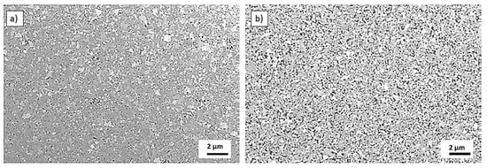
Figure 15.
FESEM micrographs of the substrate: (a) SH-5; (b) SH-15.
The FESEM micrographs of both samples indicate a homogeneous microstructure without the appearance of microstructural irregularities, such as carbide phase grouping and abnormal grain growth. The microstructure consists of very fine carbide grains that were uniformly dispersed in the Co binder. The average WC grain size was determined by the line intercept method on FESEM micrographs, as presented in Figure 16.
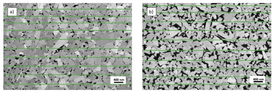
Figure 16.
Line intercept method grain size determination of the substrate at 20,000× magnification: (a) SH-5; (b) SH-15.
The mean values of carbide grain size were 187.71 ± 1.17 nm for the sample with 5 wt.% Co (SH-5) and 191.59 ± 0.82 nm for the sample with 15 wt.% Co (SH-15) was determined. The results of the quantitative analysis have shown that both of the samples contain grains that are smaller than 200 nm, which can be classified as nanograins. Thus, it is obvious that the sintering process did not lead to significant growth of the starting powders particles. This analysis also confirmed the results of coercive measurements.
Analysis of the samples by XRD method (Figure 17 and Figure 18) showed the presence of two crystal phases: WC phase with a hexagonal structure (HCP) and Co phase with a face-centered cubic (FCC) lattice. These tests, once again, confirmed the absence of unwanted eta phase and unbound carbon.
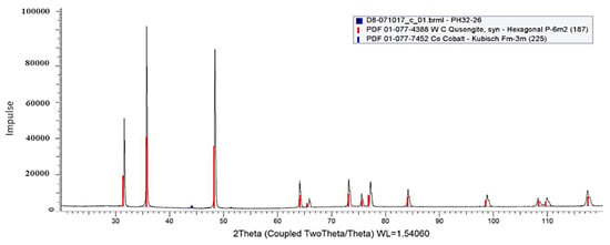
Figure 17.
X-ray diffraction (XRD) pattern of substrate SH-5.
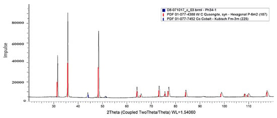
Figure 18.
XRD pattern of substrate SH-15.
Overall, the characterization results of sintered cemented carbides implied that all of the prerequisites for successfully applying thin hard PACVD coatings on these substrates are met.
3.2. Coating
The coating of metallographically unprepared (as-sintered) surface with a slightly higher surface roughness than the polished surface sought to mimic the industrial coating process and, thus, further bring the PACVD process closer to further commercialization. Table 10 presents the results of coating roughness on the unpolished (as-sintered) surface of tested samples.

Table 10.
Roughness parameters and coating thickness.
The results of coating roughness analysis showed minimal increase of characteristic parameters after coating (see Table 7). The surface roughness parameter Ra is similar before and after coating. This indicates the uniform growth of the coating over the entire surface of the substrate. It should be mentioned that slightly higher values are detected for both groups of samples, especially for the SH-15-TiBN sample. This increase could have been expected and it is attributed to the dedusting of the samples prior to coating. During dedusting, inert gas ions struck the sample surface for a few hours, which most likely caused the removal of the soft Co binder from the surface, causing an increase of surface roughness in the coated state.
The values of coating thickness determined by the Calotest method (Figure 19) implicated that Co content did not play a significant role in the growth of the coating, since both of the tested samples showed similar coating thickness.
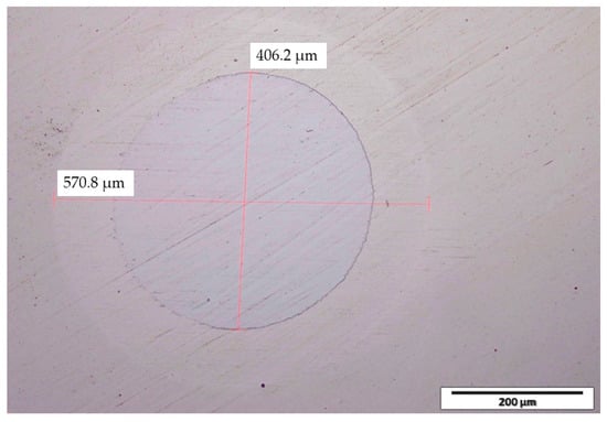
Figure 19.
Calotte on sample SH-15 after Calotest testing.
Figure 20 presents the results of XRD analysis performed on two coated samples with different Co content. Samples of WC-Co metals SH-5-B and SH-15-B are coated to yield roughly 200 mm of uniform coating consisting of interchanging titanium nitride and boron titanium layers. The major phase is the hexagonal P-6m2 tungsten carbide (WC, ICDD PDF#51-0939). The weak peak at 44° 2θ suggests the presence of hexagonal P6/mmm titanium boride (TiB2, ICDD PDF#65-8698) in trace amounts. Additionally, a weak and much broader peak at 42° 2θ suggests the presence of cubic Fm-m3 titanium nitride (TiN, ICDD PDF#38-1420). The broadness of the peak at 42° 2θ may indicate the presence of an additional phase, instead of titanium nitride, or overlapping with titanium nitride; the titanium boronitride (Ti4N3B2, ICDD PDF#87-3790). Namely, the titanium nitride and titanium boronitride phases are almost isostructural, showing very similar diffraction patterns, which does not allow a definite assignation.
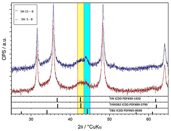
Figure 20.
XRD pattern of coated sample: SH-5-TiBN and SH-15-TiBN.
The values of the indentation modulus of elasticity (EIT) of the coating were determined based on the force (F)—indentation depth (h) curves (Figure 21) that were recorded by nanoindentation measurements and using Equations (4)–(6). Table 11 summarizes the values of EIT and TiBN coating microhardness.
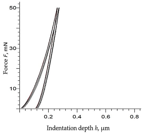
Figure 21.
The force-indentation depth curves of coated sample SH-15-TiBN.

Table 11.
Microhardness and Young’s modulus of coating.
The analysis of microhardness as one of the most important mechanical properties of the coated layer indicated a very high hardness of TiBN layer in the range from 3631 HV0.005 to 3732 HV0.005. Indentation depth during testing is significantly smaller than the thickness of the coating being ~1.6 μm (Table 10), so the possible influence of the substrate material on the test results can be discarded, as seen in Figure 21. The scatterings of the measured hardness values are not as large as could be expected due to the applied low indentation load and the high sensitivity of the method. Because quite similar hardness values were obtained for both types of coated cemented carbide substrate, regardless of the Co content and showing a significant difference in hardness obtained prior to coating, it can be concluded that the hardness of the substrate does not have a significant effect on the hardness of the coated layer.
However, it should be emphasized that the microhardness of multilayer gradient coating largely depends on the depth of indentation. Changing the indentation depth leads to changes in the layer, in which the indenter is pressed and, thus, affects the measured hardness value.
The coating adhesion testing by the Rockwell method is a simple and quick “check” of the adhesiveness of the coating. It is most often performed immediately after coating. The appearance of cracks and delamination of the coating around the indentation, due to large local stresses and pronounced plastic deformation, is visually assessed. According to VDI 3198 [43], these phenomena are classified into several classes that represent different coating adhesion, as in Table 12.

Table 12.
Classification of the coating adhesion by the Rockwell method.
The adhesion testing was carried out with three indentations per each sample. Both of the tested samples (SH-5-TiBN, SH-15-TiBN) are of the best HF1 adhesion class, since only a small number of cracks are visible on the coated surface around the indentation, as in Figure 22.
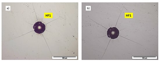
Figure 22.
Coating surface around indentation and corresponding adhesion class of coated sample: (a) SH-5-TiBN; (b) SH-15-TiBN.
The scratch test allows for the quantification of the coating adhesion by registering the characteristic delamination forces during pulling a diamond cone at a constant speed with a linear increase of force. As expected, the TiBN coated samples showed excellent properties in terms of coating adhesiveness. Both of the tested samples, regardless of the cobalt content, withstood a maximum force of 50 N without the appearance of cracks and separation of the coating (Figure 23); hence, the characteristic forces Lc1 Lc2 and Lc3 could not even be measured. Therefore, this type of coating and coating process can be considered to be very successful.

Figure 23.
Scratch after testing of the SH-15-TiBN sample.
4. Conclusions
A detailed study of cemented carbide substrates characteristics and developed surface layers produced by innovative PACVD technology was conducted. This paper provides a description of the powder mixture preparation, nano-grain WC-Co sintering process, PACVD coating process, and investigation of various properties of described substrate/complex coating systems.
The following conclusions can be drawn from the conducted research:
Using sinter-HIP process cemented carbides nano grain size samples of homogeneous microstructure, without the presence of pores, η-phases, or unbound carbon can be successfully consolidated.
- (i)
- For mixtures with higher Co content, it is necessary to increase the content of grain growth inhibitors (VC, Cr2C3) in order to maintain carbide grain size in the nano range.
- (ii)
- Utilizing nano grain size substrate allows for the achievement of higher hardness values with satisfactory fracture toughness.
- (iii)
- The Co content in the cemented carbide has a certain effect on the adhesion of the coating. The samples with a higher content of Co binder showed better adhesion, which is associated with easier cleaning of the surface and its activation in the process of dedusting before coating.
- (iv)
- A slight increase in surface roughness of coated samples when compared to the substrate material arises from ionic dedusting of the samples prior to coating due to soft Co phase ripped from the sample surface, thus yielding higher roughness parameters after coating. This is confirmed by the comparison of roughness increase for SH-15 and SH-5 samples, with a more pronounced increment of roughness being detected for the substrate with higher Co content, the SH-15 sample.
- (v)
- The cemented carbide substrate/TiBN coating system exhibited excellent physical properties and mechanical resistance, as confirmed by the obtained values of density measurements, microstructure analysis, coating adhesion tests, hardness, and fracture toughness testing.
Author Contributions
M.S. and D.Ć. conceived and designed the experiments. D.Ć. supervised the entire research, experiments and writing of the manuscript. M.S. wrote the paper, supervised sample production, and conducted mechanical, physical and adhesion properties testing. M.Š.M. supervised metallographic sample preparation, conducted scanning electron microscopy and microstructure analysis, and was involved in writing of paper, draft preparation, and visualization. All authors have read and agreed to the published version of the manuscript.
Funding
This research received no external funding.
Acknowledgments
This work is supported in part by the Croatian Science Foundation under the Project Number UIP-2017-05-6538 Nanostructured hardmetals—New challenges for Powder Metallurgy.
Conflicts of Interest
The authors declare no conflict of interest.
References
- Guo, J.; Fan, P.; Wang, X.; Fang, Z.Z. A novel approach for manufacturing functionally graded cemented tungsten carbide composites. Int. J. Powder Metall. 2011, 47, 55–62. [Google Scholar]
- Rajabi, A.; Ghazali, M.J.; Syarif, J.; Daud, A.R. Development and application of tool wear: A review of the characterization of TiC-based cermets with different binders. Chem. Eng. J. 2014, 255, 445–452. [Google Scholar] [CrossRef]
- Raihanuzzaman, R.M.; Xie, Z.; Hong, S.J.; Ghomashchi, R. Powder refinement, consolidation and mechanical properties of cemented carbides—An overview. Powder Technol. 2014, 261, 1–3. [Google Scholar] [CrossRef]
- Kübarsepp, J.; Pirso, J.; Juhani, K.; Viljus, M. Developments in cermet design, technology and performance. Int. J. Mater. Prod. Technol. 2014, 49, 160–179. [Google Scholar]
- Raoufi, M.; Mirdamadi, S.; Mahboubi, F.; Ahangarani, S.; Mahdipoor, M.S.; Elmkhah, H. Correlation between the surface characteristics and the duty cycle for the PACVD-derived TiN nanostructured films. Surf. Coat. Technol. 2011, 205, 4980–4984. [Google Scholar] [CrossRef]
- Bose, A. A perspective on the earliest commercial PM metal-ceramic composite: Cemented tungsten carbide. Int. J. Powder Metall. 2011, 47, 31–50. [Google Scholar]
- Naughton-Duszová, A.; Csanádi, T.; Sedlák, R.; Hvizdoš, P.; Dusza, J. Small-Scale Mechanical Testing of Cemented Carbides from the Micro- to the Nano-Level: A Review. Metals 2019, 9, 502. [Google Scholar] [CrossRef]
- Siewen, T.; Liu, D.; Jiang, L.; Liu, W.; Chen, Y.; Niu, Q. Microstructure and mechanical properties of functionally gradient cemented carbides fabricated by microwave heating nitriding sintering. Int. J. Refract. Hard Met. 2016, 58, 137–142. [Google Scholar]
- Kieback, B.; Dressler, M.; Jurisch, M.; Reuter, K.; Riecker, S. Micro Parts Manufacturing by Powder Metallurgy. In Proceedings of the World PM 2016, Hamburg, Germany, 9–13 October 2016; EDPMA: McLean, VA, USA, 2016. [Google Scholar]
- Pötschke, J.; Richter, V.; Mayer, M. Manufacturing and Properties of Polycrystalline WC-Co Based Cemented Carbides. In Proceedings of the World PM 2016, Hamburg, Germany, 9–13 October 2016; EDPMA: McLean, VA, USA, 2016. [Google Scholar]
- Pellan, M.; Lay, S.; Missiaen, J.M.; Norgren, S.; Angseryd, J.; Coronel, E.; Persson, T. EBSD study to analyse mechanisms of phase boundary and grain boundary development in WC-Co cemented carbides. Powder Metall. 2017, 60, 1–8. [Google Scholar] [CrossRef]
- Xie, H.; Song, X.; Yin, F.; Zhang, Y. Effect of WC/Co coherency phase boundaries on Fracture toughness of the nanocrystalline cemented carbides. Sci. Rep. 2016, 6, 31047. [Google Scholar] [CrossRef]
- Poetschke, J.; Richter, V.; Gestrich, T.; Michaelis, A. Grain growth during sintering of tungsten carbide ceramics. Int. J. Refract. Met. Hard Mater. 2014, 43, 309–316. [Google Scholar] [CrossRef]
- Lay, S.; Guyon, A.; Chaix, J.M.; Carry, C. Grain Boundary Segregation in Sintered Materials: Effect on Densification and Grain Growth. In European PM Conference Proceedings 2016; EPMA: Shrewsbury, UK, 2016. [Google Scholar]
- Klocke, F. Cutting materials, tools and coolants for machining with geometrically defined cutting edges. WZL/Fraunhofer-Inst. Prod. IPT 2013, 4, 1–60. [Google Scholar]
- Fernandes, C.M.; Senos, A.M. Cemented carbide phase diagrams: A review. Int. J. Refract. Met. Hard Mater. 2011, 29, 405–418. [Google Scholar] [CrossRef]
- e Silva, C.W.M.; Alves, E.; Ramos, A.R.; Sandu, C.S.; Cavaleiro, A. Adhesion failures on hard coatings induced by interface anomalies. Vacuum 2009, 83, 1213–1217. [Google Scholar] [CrossRef]
- Yan, P.; Rong, Y.; Wang, G. The effect of cutting fluids applied in metal cutting process. Proc. Inst. Mech. Eng. Part B J. Eng. Manuf. 2016, 230, 19–37. [Google Scholar] [CrossRef]
- Bewilogua, K.; Bialuch, I.; Ruske, H.; Weigel, K. Preparation of a-C:H/a-C:H:Si:O and a-C:H/a-C:H:Si multilayer coatings by PACVD. Surf. Coat. Technol. 2011, 206, 623–629. [Google Scholar] [CrossRef]
- Zarchi, M.; Ahangarani, S.; Sanjari, M.Z. The Role of Pecvd Hard Coatings on the Performance. Assoc. Metall. Eng. Serbia AMES 2014, 20, 15–22. [Google Scholar]
- Fabijanić, T.A.; Alar, Ž.; Ćorić, D. Influence of Consolidation Process and Sintering Temperature on Microstructure and Mechanical properties of Near Nano- and Nanostructured WC-Co Cemented Carbides. Int. J. Refract. Met. Hard Mater. 2016, 54, 82–89. [Google Scholar] [CrossRef]
- International Organization for Standardization. ISO 3369:2011. Impermeable Sintered Metal Materials and Hardmetals—Determination of Density; ISO: Geneva, Switzerland, 2011. [Google Scholar]
- International Organization for Standardization. ISO 3326:2013. Hardmetals—Determination of (the Magnetization) Coercivity; ISO: Geneva, Switzerland, 2013. [Google Scholar]
- International Organization for Standardization. ISO 6507-1:2018. Metallic Materials—Vickers Hardness Test—Part 1: Test Method; ISO: Geneva, Switzerland, 2018. [Google Scholar]
- International Organization for Standardization. ISO 28079:2009. Hardmetals—Palmqvist Toughness Test; ISO: Geneva, Switzerland, 2009. [Google Scholar]
- International Organization for Standardization. ISO 14577-1:2015. Metallic Materials—Instrumented Indentation Test for Hardness and Materials Parameters—Part 1: Test Method; ISO: Geneva, Switzerland, 2015. [Google Scholar]
- Oliver, W.C.; Pharr, G.M. Measurement of hardness and elastic modulus by instrumented indentation: Advances in understanding and refinements to methodology. J. Mater. Res. 2004, 19, 3–20. [Google Scholar] [CrossRef]
- Fabijanić, T.A.; Ćorić, D.; Musa, M.Š.; Sakoman, M. Vickers indentation fracture toughness of near-nano and nanostructured WC-Co cemented carbides. Metals 2017, 7, 143. [Google Scholar] [CrossRef]
- International Organization for Standardization. ISO 4505:2011. Hardmetals—Metallographic Determination of Porosity and Uncombined Carbon; ISO: Geneva, Switzerland, 2011. [Google Scholar]
- International Organization for Standardization. ISO 4499-2:2008. Hardmetals—Metallographic Determination of Microstructure—Part 2: Measurement of WC Grain Size; ISO: Geneva, Switzerland, 2008. [Google Scholar]
- Roebuck, B.; Gee, M.; Bennett, E.G.; Morrell, R. A National Measurement Good Practice Guide No. 20—Mechanical Tests for Hardmetals NPL. Ceramics 1999, 20, 1–74. [Google Scholar]
- WIDIA. WIDIA Master Catalog 2017, Metric; WIDIA: Fort Mill, SC, USA, 2017. [Google Scholar]
- García, J.; Ciprés, V.C.; Blomqvist, A.; Kaplan, B. Cemented carbide microstructures: A review. Int. J. Refract. Hard Met. 2019, 80, 40–68. [Google Scholar] [CrossRef]
- Oladapo ESO. Cemented Carbide with Cobalt-Molybdenum Alloy Binder. U.S. Patent US20170057878A1, 2 July 2019. [Google Scholar]
- Jia, K.; Fischer, T.E.; Gallois, B. Microstructure, hardness and toughness of nanostructured and conventional WC-Co composites. Nanostruct. Mater. 1998, 10, 875–891. [Google Scholar] [CrossRef]
- Fang, Z.; Koopman, M.; Wang, H. Cemented Tungsten Carbide Hardmetal—An Introduction. Comprehensive Hard Materials; Sarin, V.K., Ed.; Elsevier: Amsterdam, The Netherlands, 2014; pp. 123–137. [Google Scholar] [CrossRef]
- Sergejev, F.; Antonov, M. Comparative study on indentation fracture toughness measurements on cemented carbides. Proc. Estonian Acad. Sci. Eng. 2006, 12, 388–398. [Google Scholar]
- Hess, P. The mechanical properties of various chemical vapor deposition diamond structures compared to the ideal single crystal. J. Appl. Phys. 2012, 111, 051101. [Google Scholar] [CrossRef]
- Wentorf, R.H.; DeVries, R.C.; Bundy, F.P. Sintered Superhard. Mater. Sci. 1980, 208, 873–890. [Google Scholar]
- Lin, J.D.; Duh, J.G. Fracture toughness and hardness of ceria and yttria-doped tetragonal zirconia ceramics. Mater. Chem. Phys. 2002, 78, 253–261. [Google Scholar] [CrossRef]
- Weidow, J.; Andrén, H.O. APT analysis of WC-Co based cemented carbides. Ultramicroscopy 2011, 111, 595–599. [Google Scholar] [CrossRef]
- International Organization for Standardization. ISO 4499-4:2016. Hardmetals—Metallographic Determination of Microstructure—Part 4: Characterisation of Porosity, Carbon Defects and Eta-Phase Content; ISO: Geneva, Switzerland, 2016. [Google Scholar]
- VDI-Verlag. Verein Deutscher Ingenieure Normen; VDI 3198; VDI-Verlag: Dusseldorf, Germany, 1991. [Google Scholar]
Publisher’s Note: MDPI stays neutral with regard to jurisdictional claims in published maps and institutional affiliations. |
© 2020 by the authors. Licensee MDPI, Basel, Switzerland. This article is an open access article distributed under the terms and conditions of the Creative Commons Attribution (CC BY) license (http://creativecommons.org/licenses/by/4.0/).


