Article

The Effect of Wire Feeding Speed on Solidification Cracking of CMT Welding for Al-Si Alloys

1
Institute of Laser and Optoelectronic Intelligent Manufacturing, Wenzhou University, Wenzhou 325024, China
2
Department of Metals Technology and Aviation Materials, Samara National Research University, 443086 Samara, Russia
3
Suzhou Fanglin Technology Co., Ltd., High-tech Zone, Suzhou 215151, China
4
Department of Mechanical Engineering, Jamia Millia Islamia, New Delhi 110025, India
*
Author to whom correspondence should be addressed.
Metals 2021, 11(2), 267; https://doi.org/10.3390/met11020267
Submission received: 13 January 2021 / Revised: 30 January 2021 / Accepted: 1 February 2021 / Published: 4 February 2021
(This article belongs to the Special Issue High-Productivity Welding of Metals and Alloys)

Abstract

:
In this work, a welding solidification crack sensitivity test platform was established to study the effect of wire feeding speed (WFS) on solidification crack sensitivity during cold metal transfer (CMT) welding for AA6061 aluminum alloy. The test results show that as the WFS increased from 4 m/min to 5.5 m/min, the sensitivity of the solidification cracks also increased. With a further increase in the value of the WFS, the crack sensitivity decreased and eventually ceased to exist. A new perspective of the microstructure and crack propagation mechanics model was applied to understand the effect of WFS on solidification cracks. With the use of scanning electron microscopy (SEM) and a high-speed camera, it was found that as the WFS increased from 4 m/min to 5.5 m/min, the microstructure of the grain size changed from bigger to smaller, and the stability of the crystal microstructure was reduced. The crack propagation mechanics model was changed, which promotes crack propagation, increasing by 233%. When the WFS continued to increase beyond 5.5 m/min, the size of the crystal structure changed from small to big, the stability of the crystal microstructure was increased, the crack generation was suppressed, and the cracking rate was significantly reduced.

1. Introduction

The conservation of resources and energy are the key enablers of sustainable development, and the design of lightweight structures and manufacturing are directed to fulfill this aim [1,2]. High-quality and high-strength aluminum alloys are the materials of choice in developing lightweight structures. Consequently, these materials are increasingly used in the manufacture of the main structures of carrier rockets, aircraft bodies, interior, and the exterior parts of automobiles [3]. The scientific solutions to problems and technical difficulties related to the connection and joining of components such as weld cracks made from such materials have become increasingly important [4,5]. Hot crack is one of the most critical problems in welds and the manufacturing of aluminum alloy parts [6,7]. In severe cases, the cracks are so serious that the structure may crack open at the weld on solidification or break during operation. The presence of cracks severely restricts the manufacture and application of high-strength aluminum alloy welded structures [5,8]. The cold metal transfer (CMT) technology combines droplet transfer and periodic wire retraction, which can greatly reduce the welding heat input [9,10,11]. The CMT technology has a distinction in that it works on extremely low heat input and has a very stable arc. This characteristic makes CMT very suitable for the welding of aluminum alloys in bulk [11]. However, despite the advantages of solving the hot cracking problem, this problem is still the bottleneck of welding aluminum alloys through CMT technology.
Cracks in metals, especially aluminum alloys, have been investigated for their effect on the mechanisms of fatigue crack initiation and propagation [12,13,14] and to understand the relationship between processing parameters and solidification cracks [15,16]. Lin et al. [15] found that defects such as coarse secondary phases, welding porosities, and incomplete fusion can cause discontinuities such as cracks. These discontinuities caused localized stress concentrators, which initiate fatigue cracks, accelerate the crack propagation rate, and eventually result in premature fracture at the weld zone (WZ). McCullough et al. [16] employed and combined synergistic experimental and computational approaches to elucidate the underlying mechanisms of fatigue crack nucleation and crack propagation in AA6061-T6. It was demonstrated that the alloys AA6061-T6, in annealed conditions, failed in a similar number of cycles despite quantified differences in the cyclic stress–strain response. Soysal et al. [16] studied the effect of fillers on the susceptibility to solidification cracking of AA2024. The filler metal ER4145 was highly effective against solidification cracking. The ER4043 filler was less effective, and ER2319 was the least effective. Thus, in situations where solidification cracking in AA2024 welds was a major concern, ER4043 and ER4145 can be considered as filler metals.
The microstructural characterization and effect of microstructural changes on the mechanical properties of aluminum alloys have been well investigated [17,18,19,20]. A prominent microstructural feature, which affects the crack initiation in cast aluminum alloys, includes intermetallic compounds [21,22], the formation of solidification cracks, and metallurgical and mechanical factors [23,24]. The literature demonstrates that the joint microstructure closely depends on the process parameters, which in turn affect the fracture resistance significantly. The microstructural changes rely on element migration and diffusion. The investigations and results reported in the literature are helpful in understanding fatigue behavior involving crack initiation and propagation, but they do not suffice to provide insights into the relationship between macroforming and the microstructure of solidification cracks as far as wire feeding speed and solidification crack rate are concerned.

2. Materials and Methods

2.1. Materials

The base material (BM) was AA6061 aluminum alloy in an initial T6 condition with a thickness of 4 mm, as shown in Table 1. AA6061-T6 alloy is mainly composed of the elements Al-Mg-Si, with excellent formability, high strength, good weldability, and strong corrosion resistance. The typical mechanical properties of AA6061-T6 are shown in Table 2. ER4043 was used as a filler layer (FL) with a diameter of 1.2 mm, which was composed of AlSi5-ER4043 wire (ESAB, Milan, Italy), with medium strength, good corrosion resistance, and weldability.

2.2. Equipment

Figure 1 shows that the experiment was carried out by the ABB robot-assisted CMT welding system, which consists of the TPS5000 CMT digital welding system (Fronius, Pettenbach, Austria) and ABB robotic (Switzerland, Zurich). The welding machine has a rated current of 500A, and the ABB robotic is an IRB1520 robot produced by ABB, Stockholm, Switzerland. The welding machine and the robot communicated through the DeviceNet bus protocol. A scanning electron microscope (SEM) (TESCAN VEGA, Brno, Czech Republic) was used to analyze the effect of wire feeding speed on the microstructure, and a high-speed camera (CR600X2, Optronis GmbH, Kehl, Germany) was utilized to study the effect of wire feeding speed on crack propagation mechanics. The system is an integrated device, and the parameters of the experiment are composed of the WFS, welding speed, genuine length of wire, shield gas, arc length correction, and welding speed. Additionally, WFS is the crucial parameter that decides the heat input, which affects the quality of welded joints [24,25].
Table 3 gives the preconditions of the experimental process parameters for CMT welding, which were set to be the same for all experiments. For WFS, 4 m/min to 7 m/min was selected as the research object since cracks would occur in this interval during the experiment. Subsequently, the 7 sets of experiments were conducted, and then the specimens were etched with Keller’s reagent (95 mL water, 2.5 mL HNO3, 1.5 mL HCl, and 1.0 mL HF).

2.3. Characterization and Test Methods

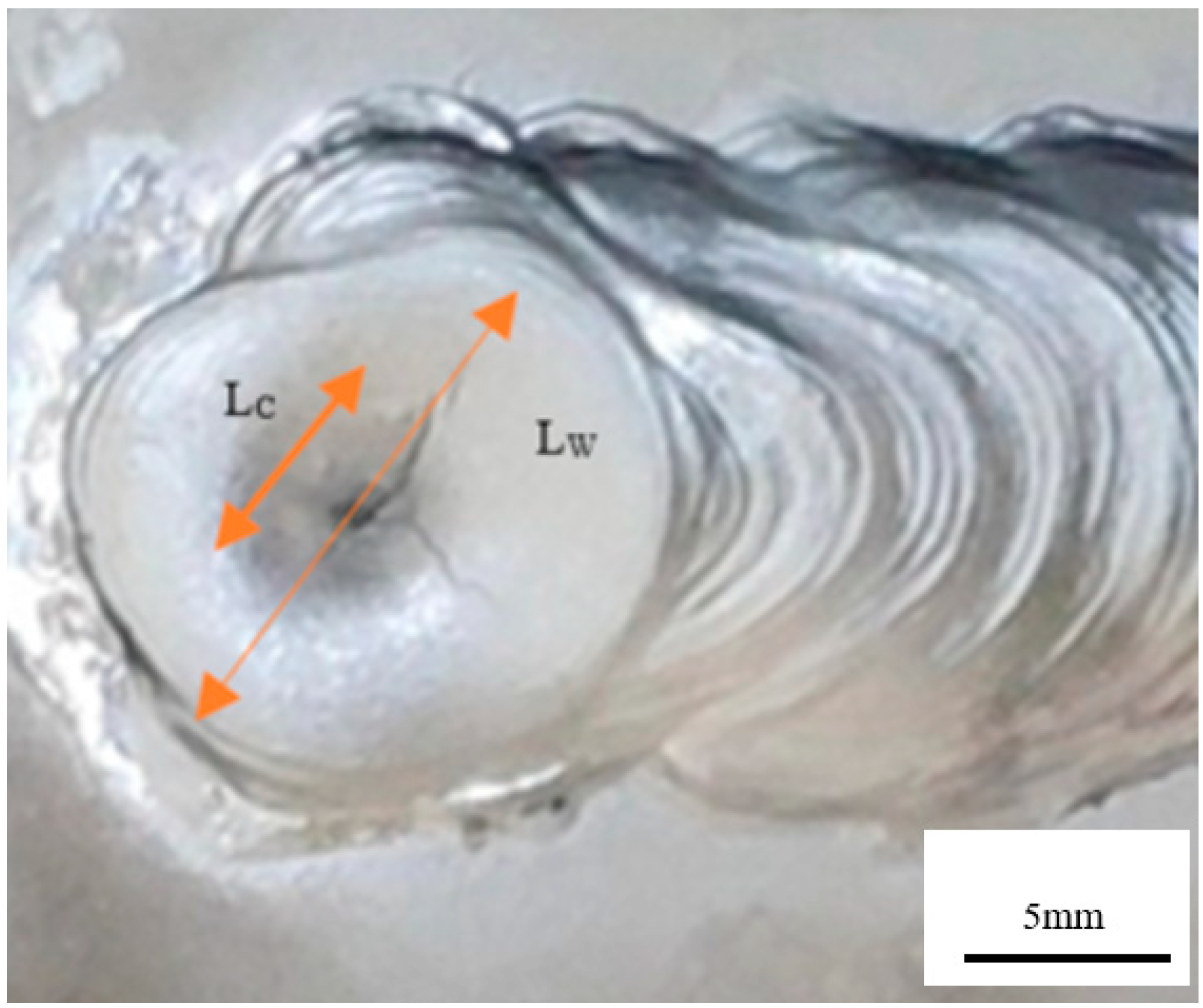
The characterization of the susceptibility to solidification cracks was carried out by measuring the length of the central crack in the weld with an optical microscope (Figure 2). The researchers estimated the solidification crack rate under different parameter combinations through the relationship given by Equation (1), where Lc is the length of the central crack, Lw is the total length of the weld, and Hc is the crack rate of the central solidified crack. The larger the value of crack rate, the higher the sensitivity of solidification cracks, and the greater the possibility of solidification cracks initiation and propagation [26]. This is Example 1 of Equation (1):
H c = L c Lw   ×   100 %
Heat input is generated in CMT welding, which is provided by the arc. In order to compare the size of the heat input reasonably and simply, the following equation (Equation (2)) is used as the calculation formula of the heat input.
E = U I V  
where, I, U, and V are the welding current, welding voltage, and welding speed, respectively.

3. Results and Discussion

3.1. Effect of Wire Feeding Speed on the Solidification Crack Rate of Aluminum Alloy

The WFS determines the amount of welding heat input and is one of the main process parameters of CMT arc welding [27]. To study the effect of the WFS on the solidification cracking of aluminum alloys, the cracks formed at varied WFSs were observed by keeping other process parameters unchanged. A WFS range from 4 m/min to 7 m/min was chosen to study since the cracks were concentrated in this interval; therefore, five equidistant discrete values, including two typical crack-free parameters in this range, were selected. The final WFSs were 4 m/min, 4.5 m/min, 5 m/min, 5.5 m/min, 6 m/min, 6.5 m/min, and 7 m/min, respectively, and the welding speed was kept constant at 8 mm/s.
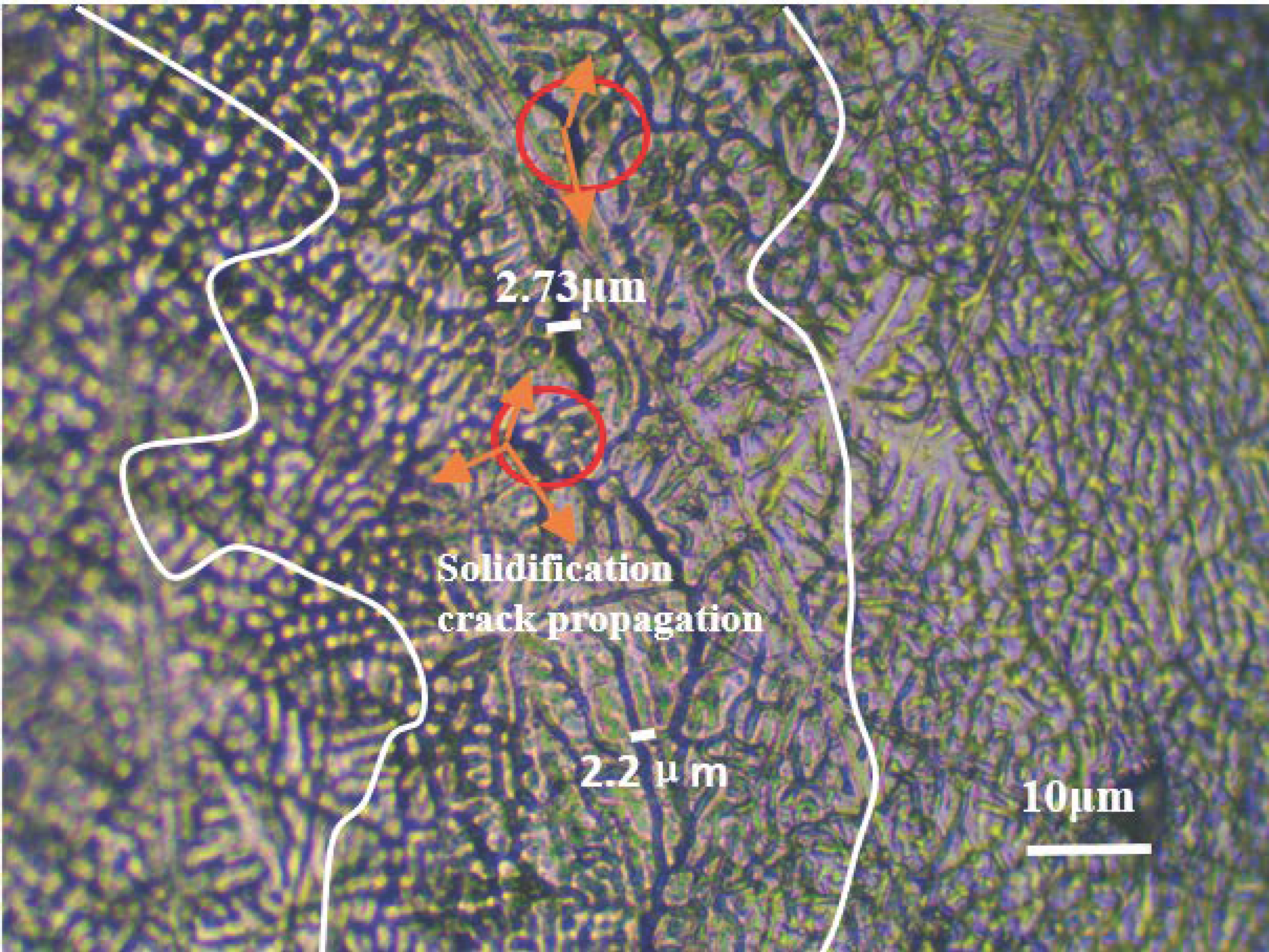
Figure 3 and Figure 4 reveal the topography of the solidification and the effect of the WFS on the central solidification crack. Figure 3 gives the topography of the solidified cracks, which provides microstructure information about the uncorroded cracks in the welding joint, and this sample corresponds to Figure 5b when the WFS is 4.5 m/min.
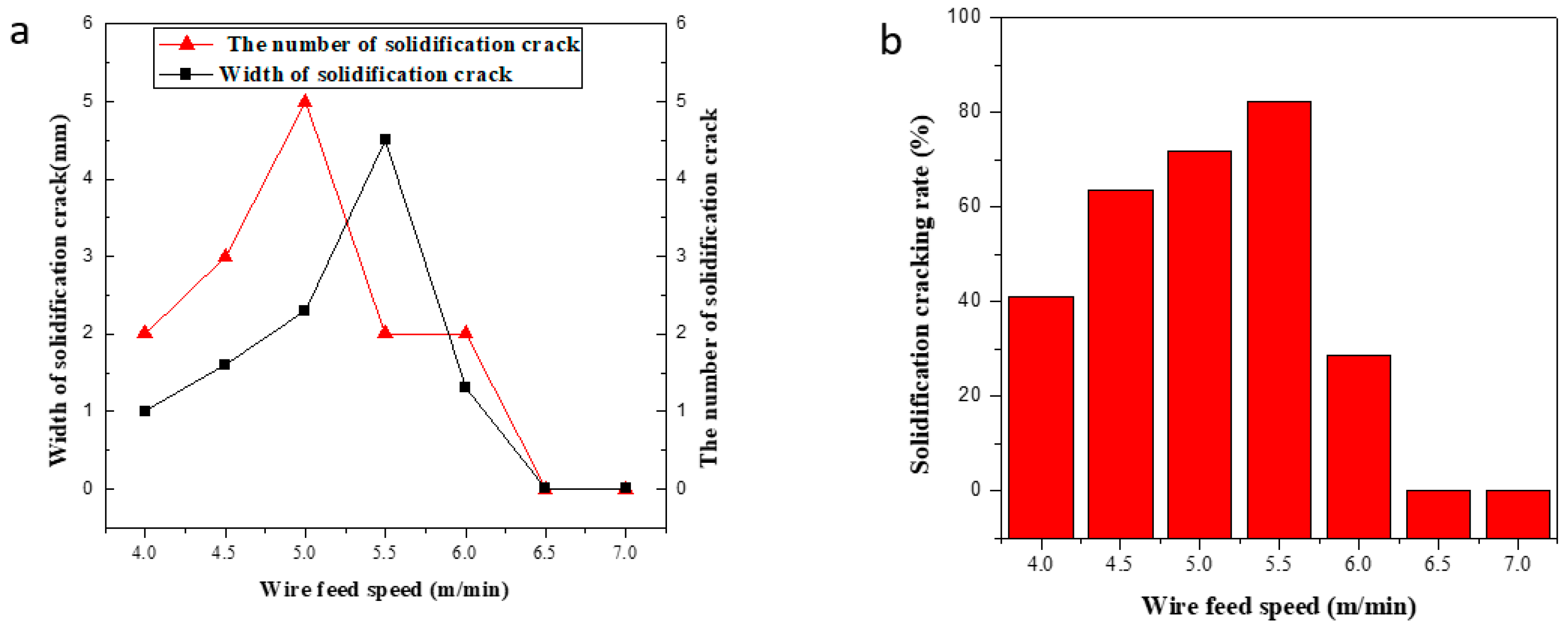
Table 4 provides the process parameters and crack rate. The measured values of the solidification crack rate are plotted against the WFS and are given in Figure 5a. The plot in Figure 5b reveals that with the increase of the WFS, the central solidification crack rate initially increases and then decreases to eventually become zero. When the WFS is less than 5.5 m/min, it is observed that the number of solidification cracks increases with the WFS and reaches a peak at 5.5 m/min. When the WFS exceeds 5.5 m/min, the crack rate begins to decrease and becomes zero at 6.5 m/min. When the WFS increases from 5.5 m/min to 6.5 m/min, the crack width and length both decrease, and the solidification rate falls rapidly to a lower value. As the WFS further increases to 6.5 m/min, the solidification cracks reduce to zero.
The analysis showed that the cracks were significantly sensitive to the WFS. When the WFS was small, the crack began to initiate and propagate, and the crack rate increased. When the WFS was increased to 5.5 m/min, the crack propagation reached the maximum value, and the maximum crack rate was found to be 82.5%. When the WFS was further increased, the crack sensitivity decreased sharply. To understand the influence of wire feeding speed on cracks from a new perspective, the microstructure and mechanical properties near the cracks were analyzed.

3.2. Effect of WFS on Microstructure

3.2.1. Effect of the WFS on the Microstructure near Cracks

As the WFS increases, the stability of the crack microstructure changes greatly. The WFS has a great influence on the stability of the microstructure caused by the formation of solidification cracks. The stability of the microstructure can be studied through the crystal structure [28,29].
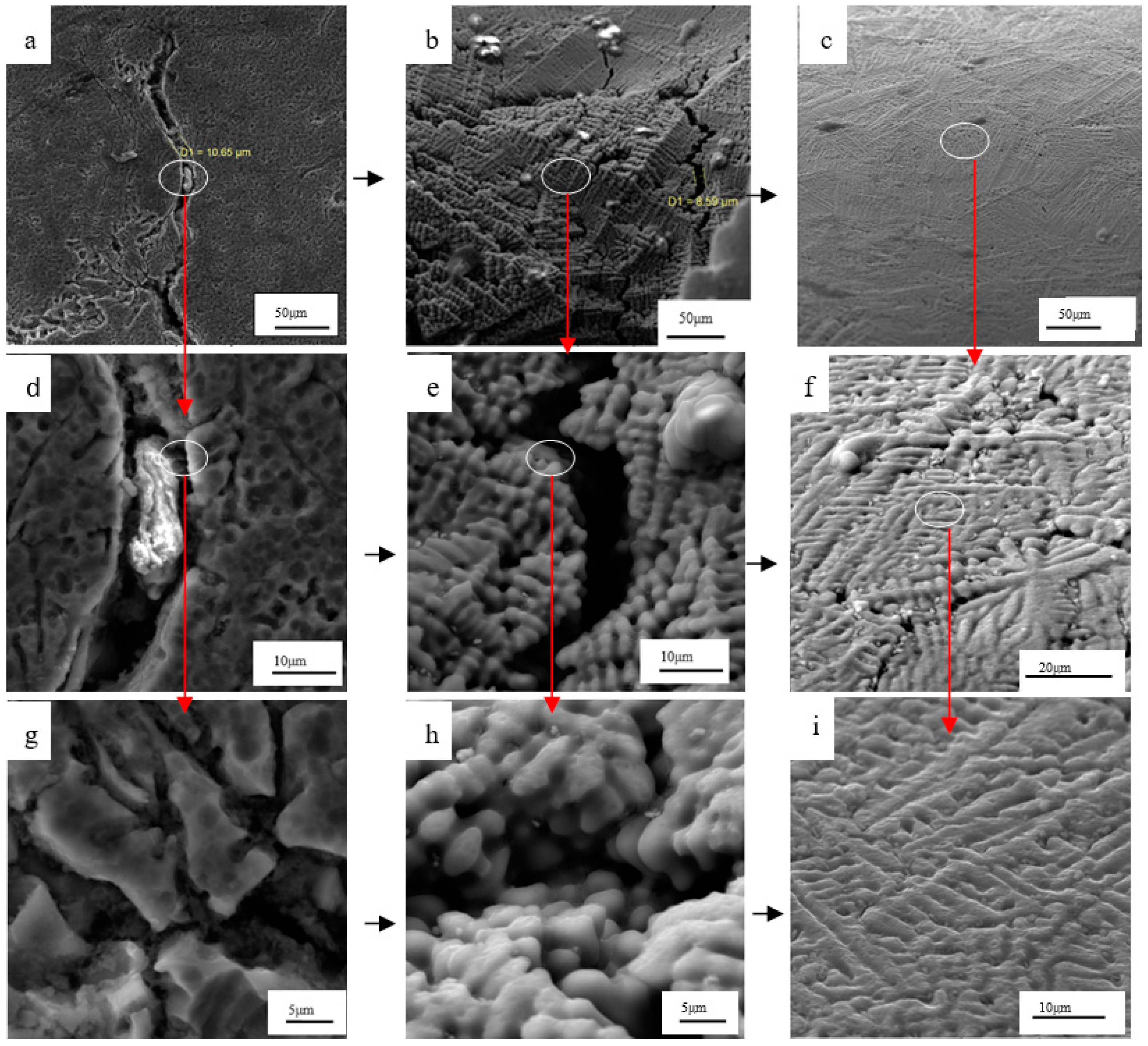
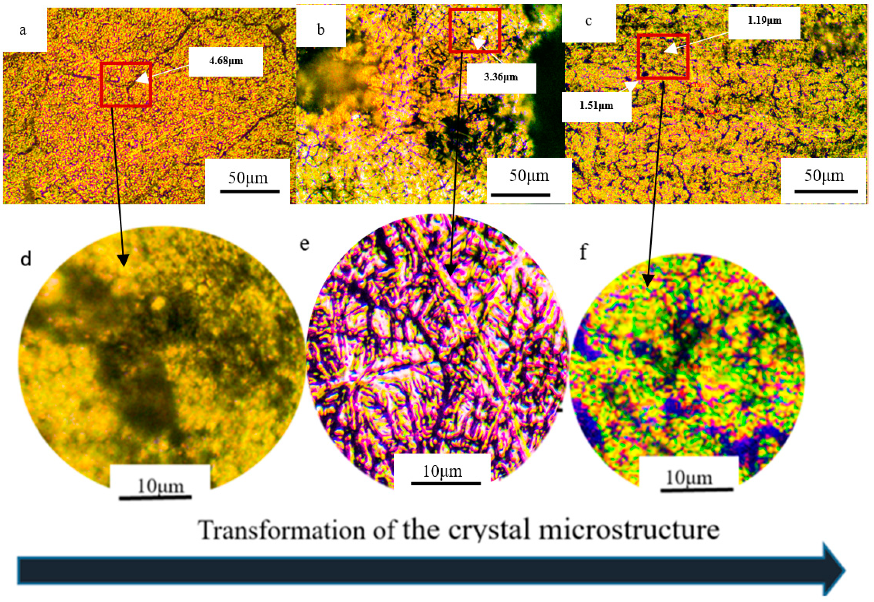
Figure 6 shows the effect of the WFS on the microstructure around the solidification cracks. When the WFS increased from 4.0 m/min to 7.0 m/min, the three most typical WFSs were selected as the research objects: 4.5 m/min, 6 m/min, and 7 m/min. The WFS of 4.5 m/min caused the increase of cracks during the experiments, and its microstructure could reflect the change in the microstructure during the crack increase process. When the WFS is 6 m/min, cracks are decreased during crack formation, which can reflect the microstructure state during the crack reduction process. When the WFS is 7 m/min, there is no crack, which can also reflect the no-crack state of the microstructure. When the WFS increases from 4.5 m/min to 6 m/min, the width of the cracks decreases, and the size of the grains also decreases. When the WFS increases from 6 m/min to 7 m/min, the cracks gradually disappear, the grains become more regular, and the microstructure is uniform.
Figure 7 shows the change in the microcrystalline structure according to the WFS near the solidification cracks. When the WFS increases from 4.0 m/min to 5.5 m/min, the consequent heat input changes from small to large; therefore, the porosity near the cracks also increases. The porosity is found to vary from smaller to larger. The results showed that as the WFS increased, the microstructure changed from simple to complex. The crack rate reached its maximum values at 5.5 m/min, and the structure near the crack consisted of more porosity. With a further increase in the WFS, the porosity decreased, and the microstructure was found to accompany protrusion. When the WFS increased beyond 5.5 m/min, the input heat increased further, and the size of the weld pool also increased.
The size and orientation of the crystal microstructure near the cracks were found to significantly change as the WFS increased from 4 m/min to 7 m/min. When the WFS increased from 4 m/min to 5.5 m/min, the crystal microstructure transformed from regular to irregular, and the size of the crystal ranged from bigger to smaller. The stability of the microstructure of the crystal was reduced. When the WFS maximized further, the size of the crystal microstructure changed from small to big, and the stability of the crystal’s microstructure increased.

3.2.2. Effect of WFS on the Crack Propagation Mechanics near Cracks

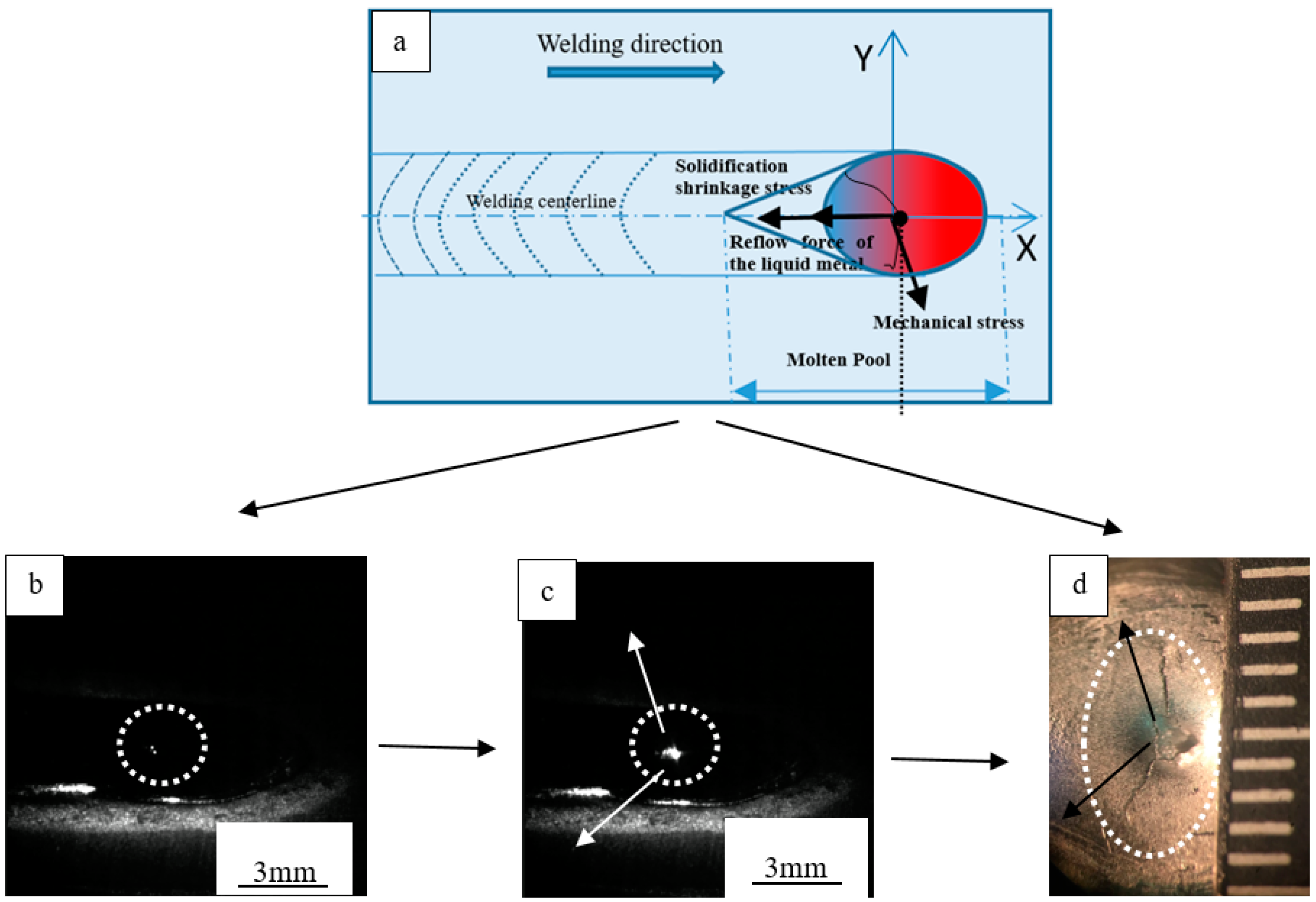
The WFS is seen to significantly affect the propagation of cracks and in turn the properties of the welding joint. The propagation of cracks is caused by mechanical stress, forces associated with the reflow of the liquid metal, and stress due to shrinkage during solidification [30,31,32]. A set of experiments were performed at various WFSs to confirm that WFS significantly affects the microstructure around the crack.
Figure 8 presents schematic diagrams showing the force analysis and the process of solidification crack formation through high-speed imaging when solidification cracks were propagated. It can be seen from Figure 8 that the molten pool is affected by three forces, namely the mechanical stress, reflow force of the liquid metal, and the solidification shrinkage stress. Through crack propagation, the influence of the WFS on solidification cracks was studied, and it was found to be related to joint quality. Experiments conducted on various WFSs confirmed that WFS will significantly affect the microstructure around the crack. Ploshikhin et al. proposed the displacement criterion to judge the propagation of solidification cracks: when the cumulative displacement of the tail of the molten pool exceeds the critical displacement of the propagating crack, the crack propagates forward [31].
In this work, the magnitude of the displacement of the grain boundary can reflect the magnitude of the resultant force. Figure 6 and Figure 7 reflect the actual change of the grain boundary of the crystal near the crack with the change of the WFS. When the WFS is small (WFS < 6.5 m/min), the weld pool’s temperature gradient is high, and the solidification speed is fast, resulting in strain at the grain boundary, the direction of which is from the tail of the molten pool at a high temperature to the center of the weld pool at a lower temperature. Therefore, the grain boundaries are expanded, and the cracks also propagate forward. Local stress has been released in the crack initiation, and it is not the dominant force; hence, in that situation, the mechanical stress had little effect on grain boundaries. When the WFS increases further (WFS ≥ 6.5 m/min), the input energy also increases, and the temperature gradient of the molten pool is small, and the solidification time is longer, so the solidification shrinkage strain on the grain boundary is small, and the mechanical stress can balance the solidification shrinkage stress. Additionally, the reflow time of the molten pool is longer, resulting in a liquid metal back to fill the crack that has been propagated; therefore, at this time, the crack propagation will not occur.
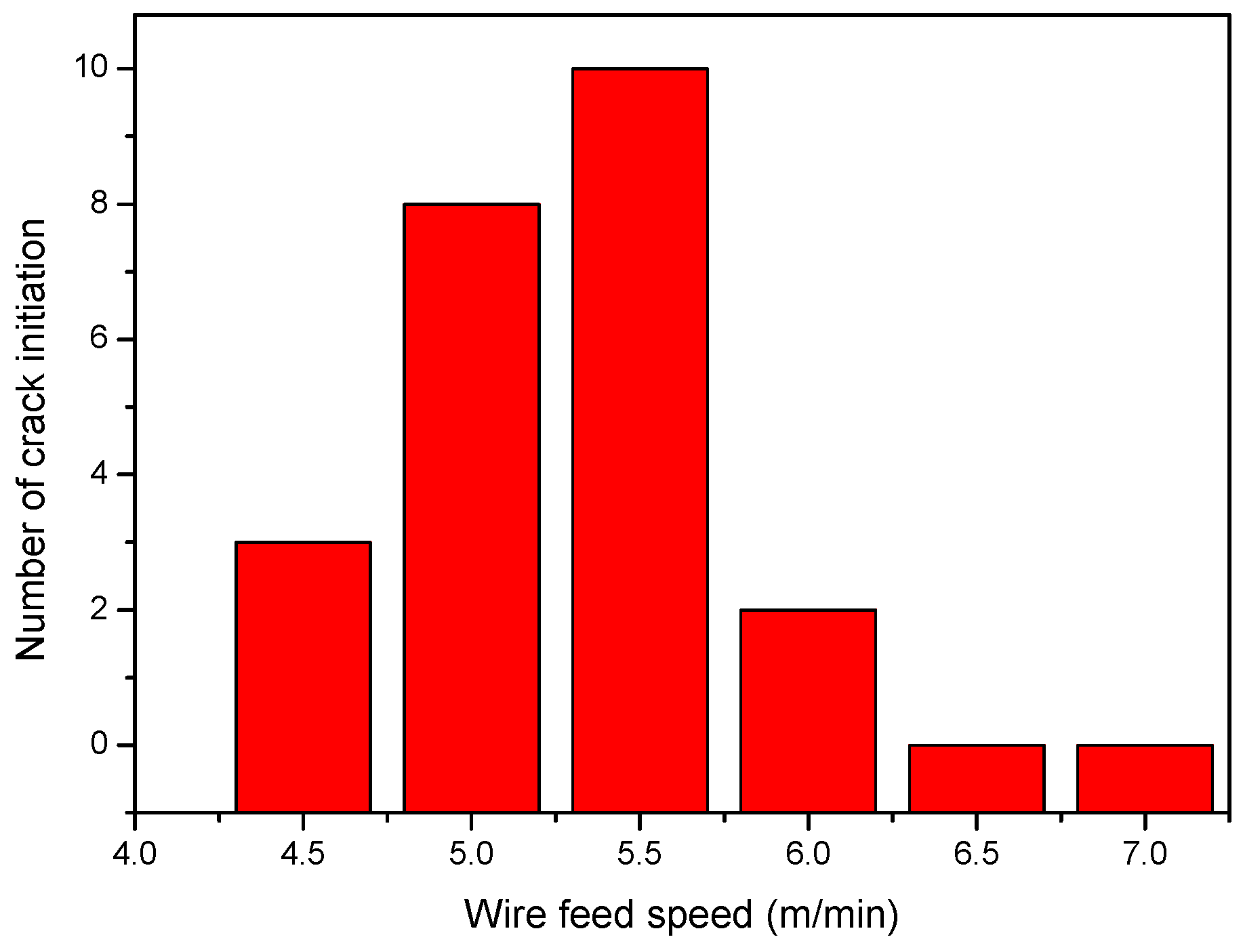
Figure 9 reveals the microstructure of the solidification crack when the crack propagates when the WFS increases from 4 m/min to 7.0 m/min, according to the crack propagation path, the red arrows represent the direction of the crack propagation. The effect of each WFS on the propagation of the solidification was analyzed. At this point, we regarded the crack that grew as a crack, selected a region randomly through SEM, and counted the number of crack propagations.
The analysis shows that a smaller WFS leads to less heat input, which leads to a smaller molten pool. The solidification crack initiation occurs at the same time as the solid and liquid phases. At this time, the strength of the grain boundary is low, and large local stress can cause the grain boundary to crack initiation [32]. An increase in the WFS caused the heat input to increase, and the strain at the tail of the molten pool also increased rapidly [33,34]. As the WFS continues to increase, the heat input also increases, so the molten pool increases, and the crack initiation area also increases. In this case, an increasing area of the molten pool with insufficient liquid metal will have more access to cause crack initiation in the grain boundaries. When the WFS increases further (WFS ≥ 6.5 m/min), the heat input also increases, but the area of the molten pool will not increase too much; in this case, the temperature gradient is small, and the solidification time is longer, causing more liquid metal to flow into the cracks that have already formed to prevent crack propagation. In such a situation, cracks will not occur.
With the above analysis, the crack propagation was found to have a significant change as the WFS increased from 4 m/min to 7 m/min. The results in Figure 10 show that when the WFS increased from 4.5 m/min to 5.5 m/min, the crack propagation mechanism was unbalanced, and the propagation of crack was promoted, with a growth rate of 233%. When the WFS was further, the crack propagation mechanics model remained in balance, the crack generation was suppressed, and the cracking rate was significantly reduced.

4. Conclusions

Through the study of the effect of wire feeding speed on solidification cracks during CMT welding for Al-Si alloys, a new perspective of the crystal microstructure and crack propagation mechanics model was applied to understand the effect of the WFS on the solidification crack. The conclusions are summarized as follows:
1. As the WFS increases from 4 m/min to 5.5 m/min, the susceptibility to solidification cracks also increases. A further increase in the WSF leads to a decrease in the susceptibility to solidification cracks and eventually ceases to exist.
2. As the WFS increases from 4m/min to 5.5 m/min, the size of the crystal microstructure changes from larger to smaller; simultaneously, the stability of the microstructure decreases. When the WFS continues to increase by 5.5 m/min, the size of the crystal microstructure changes from smaller to larger, and the stability of the crystal microstructure increases.
3. When the WFS increases from 4 m/min to 5.5 m/min, the force state of the molten pool is changed, causing crack propagation to be promoted, with a growth rate of 233%. When the WFS continues to increase at a speed of 5.5 m/min, the mechanical state is stable, which suppresses the occurrence of cracks, resulting in a significant decrease in the crack rate.

Author Contributions

Conceptualization, L.H., X.C. and S.K.; methodology, L.H., X.C., and S.K.; software, L.H. and G.L.; validation, L.H. and G.L.; formal analysis, L.H., X.C., and S.K.; investigation, L.H.; resources, X.P.; data curation, L.H. and G.L.; writing—original draft preparation, L.H.; writing—review and editing, L.H., A.N.S., X.C., and S.K.; visualization, L.H.; supervision, S.K.; project administration, X.C.; funding acquisition, X.C. All authors have read and agreed to the published version of the manuscript.

Funding

This project is supported by the Natural Science Foundation of China (Grant No. 51975419), Zhejiang Provincial Natural Science Foundation of China under Grant No. LY20E050027, Key Research and Development Project Zhejiang Province (2021C04022), and China Scholarship Council.

Data Availability Statement

The data presented in this study are available on request from the corresponding author.

Acknowledgments

The authors would like to thank Melnikov A. (Samara National Research University) for his support in the OM-SEM-EDS analysis of the samples.

Conflicts of Interest

The authors declare no conflict of interest.

References

  1. Raabe, D.; Tasan, C.C.; Olivetti, E.A. Strategies for improving the sustainability of structural metals. Nature 2019, 575, 64–74. [Google Scholar] [CrossRef] [Green Version]
  2. Nobrega, J.H.C.; Pio, P.G.C.; Fernandes, G.L.; Botêlho, S.T.; Araujo, T.C.; Anholon, R.; Ordóñez, R.E.C.; Rampasso, I.S.; Leal Filho, W.; Quelhas, O.L.G. Sustainability in manufacturing processes: Practices performed in metal forming, casting, heat treatment, welding and electrostatic painting. Int. J. Sustain. Dev. World Ecol. 2019, 26, 684–697. [Google Scholar] [CrossRef]
  3. Imran, M.; Khan, A.R.A. Characterization of Al-7075 metal matrix composites: A review. J. Mater. Res. Technol. 2019, 8, 3347–3356. [Google Scholar] [CrossRef]
  4. Zhang, J.; Song, B.; Wei, Q.; Bourell, D.; Shi, Y. A review of selective laser melting of aluminum alloys: Processing, microstructure, property and developing trends. J. Mater. Sci. Technol. 2019, 35, 270–284. [Google Scholar] [CrossRef]
  5. Chen, L.; Wang, C.; Xiong, L.; Zhang, X.; Mi, G. Microstructural, porosity and mechanical properties of lap joint laser welding for 5182 and 6061 dissimilar aluminum alloys under different place configurations. Mater. Des. 2020, 191, 108625. [Google Scholar] [CrossRef]
  6. Filin, V.Y.; Ilyin, A.V. On the fracture mechanics based development of cleavage fracture resistance criteria for the materials of large-size welded structures. Procedia Struct. Integr. 2019, 14, 758–773. [Google Scholar] [CrossRef]
  7. Marazani, T.; Madyira, D.M.; Akinlabi, E.T. Repair of Cracks in Metals: A Review. Procedia Manuf. 2017, 8, 673–679. [Google Scholar] [CrossRef]
  8. Li, R.; Wang, M.; Li, Z.; Cao, P.; Yuan, T.; Zhu, H. Developing a high-strength Al-Mg-Si-Sc-Zr alloy for selective laser melting: Crack-inhibiting and multiple strengthening mechanisms. Acta Mater. 2020, 193, 83–98. [Google Scholar] [CrossRef]
  9. Ortega, A.G.; Corona Galvan, L.; Salem, M.; Moussaoui, K.; Segonds, S.; Rouquette, S.; Deschaux-Beaume, F. Characterisation of 4043 aluminium alloy deposits obtained by wire and arc additive manufacturing using a Cold Metal Transfer process. Sci. Technol. Weld. Join. 2019, 24, 538–547. [Google Scholar] [CrossRef] [Green Version]
  10. Wojdat, T.; Kustroń, P.; Margielewska, A.; Stachowicz, M. Microstructure and mechanical properties of braze welded joints of copper with austenitic steel made by CMT method. Arch. Metall. Mater. 2019, 64, 1411–1420. [Google Scholar] [CrossRef]
  11. Chen, X.; Su, C.; Wang, Y.; Siddiquee, A.N.; Sergey, K.; Jayalakshmi, S.; Singh, R.A. Cold Metal Transfer (CMT) Based Wire and Arc Additive Manufacture (WAAM) System. J. Surf. Investig. X-ray Synchrotron Neutron Tech. 2018, 12, 1278–1284. [Google Scholar] [CrossRef]
  12. Zerbst, U.; Klinger, C. Material defects as cause for the fatigue failure of metallic components. Int. J. Fatigue 2019, 127, 312–323. [Google Scholar] [CrossRef]
  13. Maruschak, P.O.; Chausov, M.G.; Konovalenko, I.V.; Yasnii, O.P.; Panin, S.V.; Vlasov, I.V. Effect of Shock and Vibration Loading on the Fracture Mechanisms of a VT23 Titanium Alloy. Strength Mater. 2020, 52, 252–261. [Google Scholar] [CrossRef]
  14. Lin, S.; Deng, Y.-L.; Tang, J.-G.; Deng, S.-H.; Lin, H.-Q.; Ye, L.-Y.; Zhang, X.-M. Microstructures and fatigue behavior of metal-inert-gas-welded joints for extruded Al-Mg-Si alloy. Mater. Sci. Eng. A 2019, 745, 63–73. [Google Scholar] [CrossRef]
  15. McCullough, R.R.; Jordon, J.B.; Allison, P.G.; Rushing, T.; Garcia, L. Fatigue crack nucleation and small crack growth in an extruded 6061 aluminum alloy. Int. J. Fatigue 2019, 119, 52–61. [Google Scholar] [CrossRef]
  16. Soysal, T.; Kou, S. Effect of filler metals on solidification cracking susceptibility of Al alloys 2024 and 6061. J. Mater. Process. Technol. 2019, 266, 421–428. [Google Scholar] [CrossRef]
  17. Borsato, T.; Ferro, P.; Berto, F.; Carollo, C. Effect of Solidification Time on Microstructural, Mechanical and Fatigue Properties of Solution Strengthened Ferritic Ductile Iron. Metals 2018, 9, 24. [Google Scholar] [CrossRef] [Green Version]
  18. Liu, K.; Chen, X.; Shen, Q.; Pan, Z.; Singh, R.A.; Jayalakshmi, S.; Konovalov, S. Microstructural evolution and mechanical properties of deep cryogenic treated Cu–Al–Si alloy fabricated by Cold Metal Transfer (CMT) process. Mater. Charact. 2020, 159, 110011. [Google Scholar] [CrossRef]
  19. Balachandramurthi, A.R.; Moverare, J.; Dixit, N.; Deng, D.; Pederson, R. Microstructural influence on fatigue crack propagation during high cycle fatigue testing of additively manufactured Alloy 718. Mater. Charact. 2019, 149, 82–94. [Google Scholar] [CrossRef]
  20. Zhang, J.; Zhao, Z.; Kong, Y.; Zhang, Z.; Zhong, Q. Crack initiation and propagation mechanisms during thermal fatigue in directionally solidified superalloy DZ125. Int. J. Fatigue 2019, 119, 355–366. [Google Scholar] [CrossRef]
  21. Wang, X.; Lu, F.; Wang, H.-P.; Qu, Z.; Xia, L. Micro-scale model based study of solidification cracking formation mechanism in Al fiber laser welds. J. Mater. Process. Technol. 2016, 231, 18–26. [Google Scholar] [CrossRef]
  22. Tian, X.; Shi, Q. Preventing welding hot cracking by welding with an intensive trailing cooler. J. Mater. Process. Technol. 2000, 97, 30–34. [Google Scholar] [CrossRef]
  23. Tomków, J.; Fydrych, D.; Rogalski, G. Dissimilar underwater wet welding of HSLA steels. Int. J. Adv. Manuf. Technol. 2020, 109, 717–725. [Google Scholar] [CrossRef]
  24. Tomków, J.; Sobota, K.; Krajewski, S. Influence of tack welds distribution and welding sequence on the angular distortion of tig welded joint. Facta Univ. Ser. Mech. Eng. 2020, 18, 611–621. [Google Scholar] [CrossRef]
  25. Bellet, M.; Cerri, O.; Bobadilla, M.; Chastel, Y. Modeling Hot Tearing during Solidification of Steels: Assessment and Improvement of Macroscopic Criteria through the Analysis of Two Experimental Tests. Metall. Mater. Trans. A 2009, 40, 2705–2717. [Google Scholar] [CrossRef] [Green Version]
  26. Wang, P.; Hu, S.; Shen, J.; Liang, Y. Characterization the contribution and limitation of the characteristic processing parameters in cold metal transfer deposition of an Al alloy. J. Mater. Process. Technol. 2017, 245, 122–133. [Google Scholar] [CrossRef]
  27. Kumar, P.; Ramamurty, U. Microstructural optimization through heat treatment for enhancing the fracture toughness and fatigue crack growth resistance of selective laser melted Ti 6Al 4V alloy. Acta Mater. 2019, 169, 45–59. [Google Scholar] [CrossRef]
  28. Dong, T.; Gao, C.; Li, L.; Pei, Y.; Li, S.; Gong, S. Effect of substrate orientations on microstructure evolution and stability for single crystal superalloys in rapid solidification process. Mater. Des. 2017, 128, 218–230. [Google Scholar] [CrossRef]
  29. Xu, J.; Lin, X.; Guo, P.; Dong, H.; Wen, X.; Li, Q.; Xue, L.; Huang, W. The initiation and propagation mechanism of the overlapping zone cracking during laser solid forming of IN-738LC superalloy. J. Alloys Compd. 2018, 749, 859–870. [Google Scholar] [CrossRef]
  30. Scutelnicu, E.; Rusu, C.C. Assessment of cooling rate in longitudinal welded pipelines performed by submerged double-arc welding. Int. J. Mech. 2014, 8, 144–149. [Google Scholar]
  31. Ploshikhin, V.; Prikhodovski, A.; Ilin, A.; Heimerdinger, C.; Palm, F. Computer Aided Development of the Crack-Free Laser Welding Processes. Key Eng. Mater. 2007, 1984–1994. [Google Scholar] [CrossRef]
  32. Kou, S. A criterion for cracking during solidification. Acta Mater. 2015, 88, 366–374. [Google Scholar] [CrossRef]
  33. Agarwal, G.; Kumar, A.; Richardson, I.M.; Hermans, M.J.M. Evaluation of solidification cracking susceptibility during laser welding in advanced high strength automotive steels. Mater. Des. 2019, 183, 108104. [Google Scholar] [CrossRef]
  34. Boettinger, W.J.; Banerjee, D.K. Solidification. In Physical Metallurgy; Elsevier: Amsterdam, The Netherlands, 2014; pp. 639–850. ISBN 9780444537713. [Google Scholar]
Figure 1. Cold metal transfer (CMT) processing experimental equipment and process. (a) CMT welding solidification crack test platform; (b) CMT welding processing; (c) research process.
Metals 11 00267 g001
Figure 2. Processing sample map of the crack rate measurement experiment.
Metals 11 00267 g002
Figure 3. Topography of the solidified cracks.
Metals 11 00267 g003
Figure 4. Effect of wire feeding speed on the solidification cracking of the aluminum alloy: (a) 4 m/min; (b) 4.5 m/min; (c) 5 m/min; (d) 5.5 m/min; (e) 6 m/min; (f) 6.5 m/min; (g) 7.0 mm/min.
Metals 11 00267 g004
Figure 5. (a) Effect of wire feeding speed on the width and number of cracks; (b) effect of wire the feeding speed on the crack rate.
Metals 11 00267 g005
Figure 6. Influence of wire feeding speed on the microstructure near the solidification cracks: (a,d,g) 4.5 m/min; (b,e,h) 6 m/min; (c,f,i) 7 m/min.
Metals 11 00267 g006
Figure 7. Transformation of the microstructure of crystals under different wire feeding speeds: (a,d) 5 m/min; (b,e) 5.5 m/min; (c,f) 6.5 m/min.
Metals 11 00267 g007
Figure 8. Crack propagation and force analysis: (a) schematic diagram of the force analysis during crack propagation; (b) early stage of the propagation; (c) middle stage of the propagation; (d) actual crack forming.
Metals 11 00267 g008
Figure 9. Microscopic image of solidification crack propagation: (a) 4 m/min; (b) 4.5 m/min; (c) 5.0 m/min; (d) 5.5 m/min; (e) 6 m/min; (f) 6.5 m/min; (g) 7.0 m/min.
Metals 11 00267 g009
Figure 10. Number of solidification crack propagations.
Metals 11 00267 g010
Table 1. Chemical composition of 6061 and 4043 aluminum alloy (wt%).
CompositionSiMgFeCuZnAl
AA6063 (BM)0.4–0.80.8–1.2<0.70.15–0.40.25Bal.
ER4043 (FL)5.000.10.040.050.1Bal.
Table 2. Typical mechanical properties of AA6061-T6.
Material Yield Strength (MPa)Ultimate Tensile Strength (MPa)Elongation (%)
AA6061-T6 331.5358.513
Table 3. Preconditions of the experimental process parameters for CMT welding.
Process ParametersExperimental Conditions
Genuine length of the wire8 mm
Shield gas 8 L/min, 100% Argon
Arc length correction0%
Welding speed 8 mm/s
Table 4. Process parameters and the crack rate of CMT welding processing.
SampleWire Feeding Speed
(m/min)
Current
(A)
Voltage
(V)
Heat Input
(J/mm)
Crack Rate
(%)
148816.6182.640.91
24.510016.9211.2563.64
3511317.2242.9572.00
45.512517.5273.4382.5
5613618.1307.728.67
66.514818.6344.10
7715819.2379.20
Publisher’s Note: MDPI stays neutral with regard to jurisdictional claims in published maps and institutional affiliations.