Article

Effect of MgO Content on the Viscosity, Foaming Life, and Bonding in Liquid and Liquid/Solid CaO-SiO2-MgO-5Al2O3-30FeO Slags

Department of Materials Science and Engineering, National Chung Hsing University, 145 Xingda Rd., South Dist., Taichung City 40227, Taiwan
*
Author to whom correspondence should be addressed.
Metals 2021, 11(2), 249; https://doi.org/10.3390/met11020249
Submission received: 29 December 2020 / Revised: 28 January 2021 / Accepted: 30 January 2021 / Published: 2 February 2021

Abstract

:
The CaO-SiO2-MgO-5Al2O3-30FeO five (oxide) components slag system was studied by varying the magnesium oxide (MgO) content (5.7–13.6 wt.%.% MgO) and keeping the basicity constant). The data were analyzed using the FactSage software. It was observed that the liquid network structure and precipitation of solid particles had an impact on high-temperature viscosity and foaming life. Under the same basicity (mass ratio CaO/SiO2 = 1.5) and at a temperature of 1500 °C, the MgO content was varied as 5.7 wt.%, 7.4 wt.%, 9.6 wt.%, 11.5 wt.%, and 13.6 wt.% in A0~A5. The solid fractions of different samples were estimated with FactSage software and found to be A0–A2 (0 wt.%), A3 (2.77 wt.%), A4 (6.92 wt.%), A5 (11.7 wt.%). The viscosities of A0–A5 measured at 1500 ·C were 22, 47, 40, 76, 363, and 1088 mPa×s, respectively, and the foaming life was 2.0 min, 7.7 min, 6.2 min, 13.4 min, 16.8 min, and 18.0 min, respectively. It was found that A5 exhibits the best effective foaming life under these environmental conditions because it can ex-hibit a double foaming effect formed by the precipitation of solid particles. The Si-O-Si network in liquid slag also contributed to foaming life, when there was only liquid slag bonding in the slag, the effective foaming life was 7.7 min. In the absence of these factors, the foaming life was only 2 min.

1. Introduction

The advancement of the electric arc furnace smelting technology has reduced the average smelting time from 3 h to 45 min [1]. The generation of foamed slag, formed after the scrap is melted, significantly affects the quality of steel grades and helps in saving energy [1]. Literature reports suggest that foaming slag in an electric arc furnace can effectively improve the efficiency of the process and reduce the cost of the method. Pan et al. [2] reported the formation of heat-insulating foamed slag. Liang [3] reported that the foaming process could reduce power consumption, resulting in the cost-efficiency of the process. He pointed out that the oxidation of the graphite electrode can be inhibited if a high-temperature graphite electrode coated with foam slag is used. Thus, the rate of graphite consumption is lowered. These results confirm that the use of foamed slag reduces the cost of the electric arc furnace steelmaking process.
The slag foaming process can be optimized in two ways. The supersaturated solid-phase particles can be precipitated [4]. The presence of solidified phase particles in the slag can increase its viscosity [5]. The higher the solidified phase fraction is, the higher the dynamic viscosity of the solid–liquid phase would be [6]. This helps to optimize the foaming process. Some studies report that the solidified phase particles can increase the viscosity and promotes the formation and stabilization of the foam of the slag. In the absence of a solidified phase, the viscosity is too low and is not conducive to foam formation [7]. Therefore, it is important to identify the slag composition that can be used to achieve optimum viscosity.
The network bonding in liquid slag also affects the optimization process. According to previous experiments [8,9], in a basic slag environment, SiO2 tends to form a network and is known as the Network former (NWF). MgO and CaO tend to break the network bonds and are known as the Network modifiers (NWMs). SiO4 exhibits a tetrahedral structure. Depending on the nature of the coordinated oxygen ions, the oxygen units are labeled as non-bridging oxygen (NBO) (oxygen ion state: O) where the terminal oxygen is connected to Si at one side or the bridging oxygen (BO) units (oxygen ion state: O0) where the non-terminal oxygen ion is connected to Si on both sides. The free oxygen ion (Free oxygen, FO; oxygen ion state: O2−) is an independent oxygen ion where both sides are not connected to Si. The free oxygen ions are found in MgO and CaO. The viscosity of the liquid slag increases with increasing NWF in the slag [10]. This research aims to investigate if the foaming life can be prolonged by employing a combination of the silica network formation and solid precipitation mechanisms in the electric furnace steelmaking process. We also aimed to study if a modified slag, possessing the properties of the solidified phase precipitates and liquid slag bonding, can be formed.

2. Materials and Methods

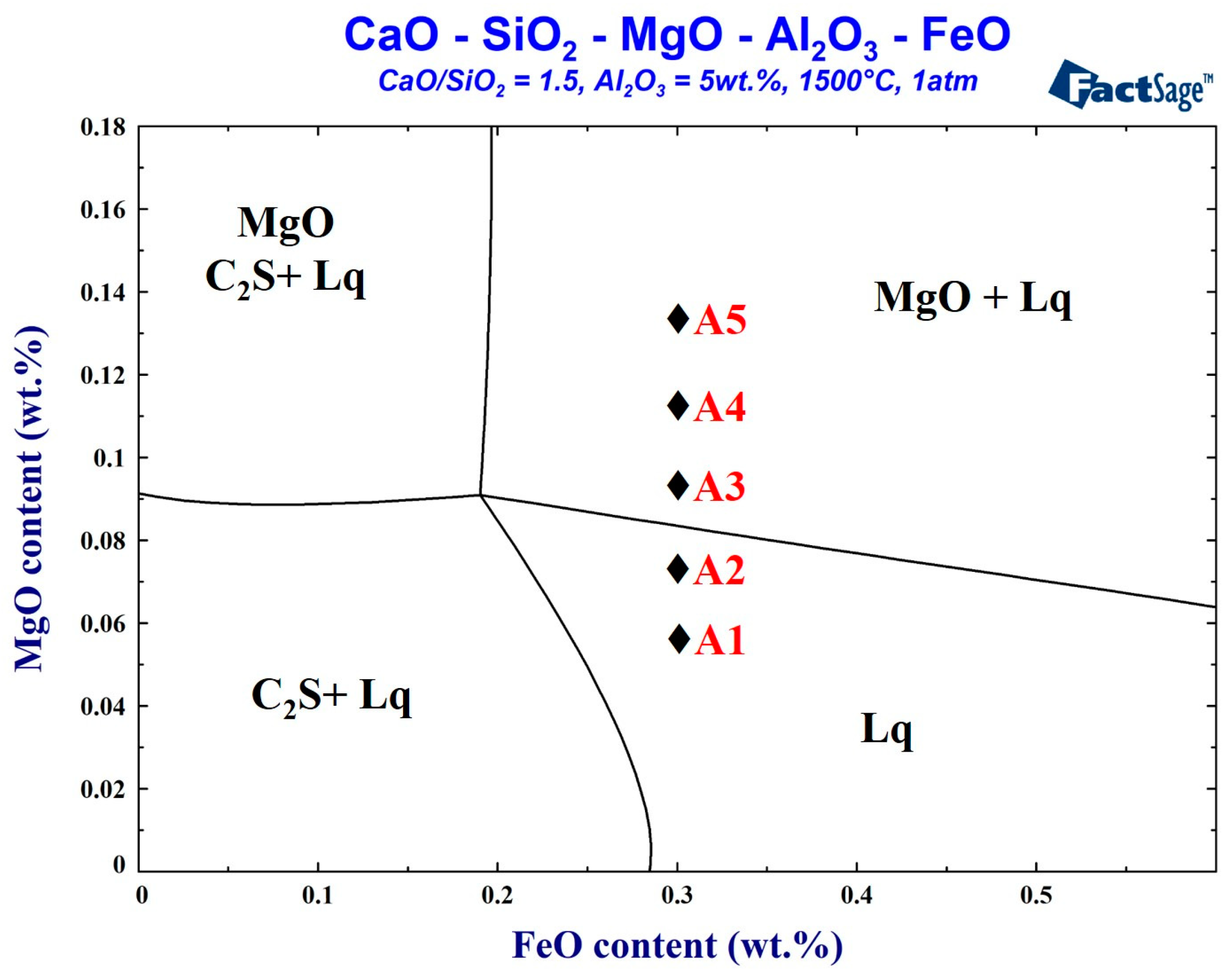
2.1. Slag Sampling and Characterization

This study is based on the actual slag obtained during the smelting period during a real steelmaking process. The FactSage thermodynamics software (version 7.3, Thermfact Ltd, Quebec QC, Canada) was used to simulate the change in the MgO content at 1500 °C. Its influence on the foaming performance was evaluated. The control sample A0 was the foaming slag (C/S = 2.8, FeO = 29 wt.%) used in the steel plant. The five samples of foaming slags were studied, respectively, the total liquid phase composition slag, and the MgO supersaturated precipitation slag. The five samples of the foaming slags were simulated and designed using the FactSage software. The samples were melted and transformed into their liquid state using a high-frequency furnace (Five Powers Electric Machinery Mfg Co., Ltd., Taipei, Taiwan). Following this, the samples were water quenched. The wavelength-dispersive X-ray Fluorescence (WDS-XRF) technique (Rigaku, Tokyo, Japan) was used to analyze the slag composition. Therefore, the redox titration method is used to confirm the Fe2+ concentration of the slag, and the FeO content is obtained by conversion. The six samples of the foaming slag compositions are shown in Table 1. The FactSage simulated foaming slag phase diagram is shown in Figure 1. The basicity was fixed at 1.5, and the alumina content was 5 wt.%. When the FeO content was 30 wt.%, MgO reached saturation in the slag system (8.3 wt.%, Table 1). The aim was to determine the influence of varying amounts of MgO on the foaming properties under conditions of unsaturation or at different levels of supersaturation.

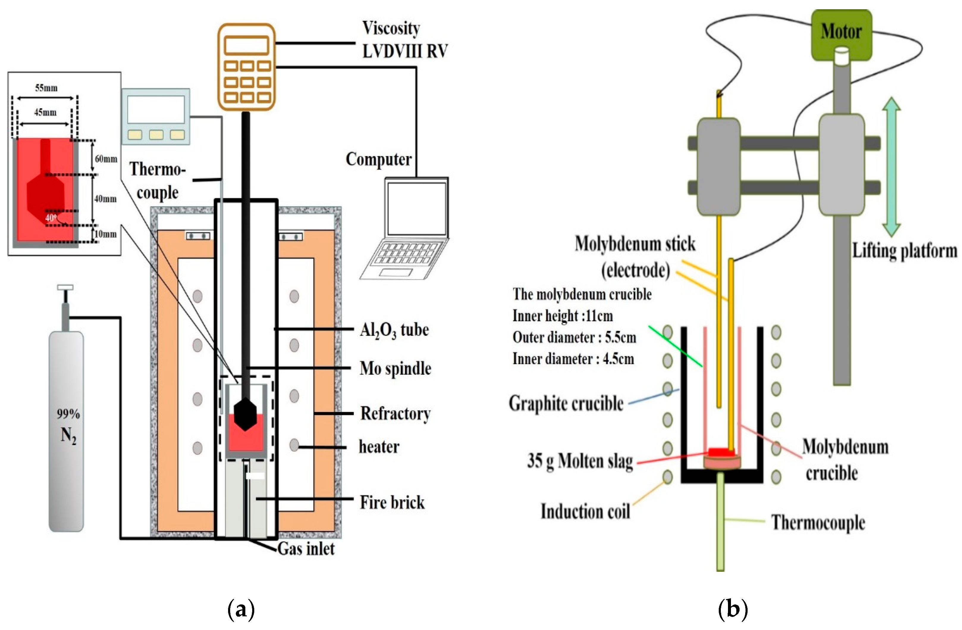
2.2. Viscosity and Foaming Life

The Brookfield LVDVIII RV (AMETEK Brookfield, Middleboro MA, USA), equipped with a high-temperature furnace system with a maximum temperature limit of 1640 °C. Thermocouples were used in Pt-10%Rh/Pt monitoring instruments, as shown in Figure 2a, and the system was used for the experiments. Before the viscosity measurement, standard silicone oil samples with the viscosity of 0.0986, 0.476, and 0.973 Pa·s were used to calibrate the spindle at room temperature. When starting the experiment, the temperature increased in two stages: Initially, the rate of increase was 10 °C/min (from room temperature to 1300 °C). The rate of increase was 2 °C/min (from 1300 °C to 1640 °C) in the next stage. The sample (140 g) was placed in a molybdenum crucible. When the slag temperature rose and the viscosity reached the test range of the instrument, the molybdenum rotor was gradually lowered to a distance of 10 mm from the bottom. The rotation speed was set to 20 rpm, and continued heating while measuring the viscosity. In order to avoid the oxidation of Mo crucible and Mo spindle, and to prevent changes in the iron oxide content, the nitrogen gas (99.0%) was used at a flow rate of 0.5 NL/min. Viscosity data are a continuous curve that changes with temperature. In order to confirm the reproducibility of viscosity measurements, this study repeats the experiment for slags A3 and A5, and take the average data at each temperature.
The schematic diagram of the foaming life test device (Jia Shing Electricity Construction Co, Kaohsiung, Taiwan) is shown in Figure 2b. The schematic diagram in Figure 2b illustrates the method of measuring the height of the foaming slag. The slag sample was kept in the molybdenum crucible, and the graphite crucible was used as the heating medium. The sample was heated in a high-temperature furnace system at a temperature of 1500 °C. The graphite powder was reacted with the slag to produce a fixed amount of carbon monoxide gas. The fixed molybdenum electrode was inserted into the molten slag, and the electrode was moved in an up and down direction. When the moving molybdenum electrode came into contact with the slag, it formed a conduction loop to generate current and resistance. Thus, the position of the moving molybdenum electrode could be recorded when it was turned on for the first time to determine the current foaming height.
The foam life test is similar to the study of Corbari et al. [11]. In this study, the fixed electrode is inserted into the slag. When the moving electrode descends into the slag, a current loop is formed to measure the voltage value, and the current position is the slag height. The experimental method is to put 35 g of foaming slag into the molybdenum crucible (inner height 11 cm, outer diameter 5.5 cm, inner diameter 4.5 cm), and placed the molybdenum crucible in the graphite crucible. After reaching the target temperature (1500 °C), the original height of the slag was measured first, and then 1.2 g of carbon powder was added to the bottom of the slag through a molybdenum blowpipe. Then, the reaction produces CO bubbles (the reaction is completed in about 1.5–2 min) and replenishes the consumed FeO. After the measurement of foam life and viscosity, the molten slag was water quenched and the composition analysis was performed to confirm that the FeO composition was unchanged.
The foaming life has been defined as the time taken for the foaming height to drop back to the original height. The time required for this reaction process is defined as foaming life. The foaming property is usually taken as the height of the foaming level. When the same volume of gas is produced, the longer the foaming time, the longer the foam can last without breaking, improving the insulation effect. Therefore, each sample under study uses the same amount of carbon powder to produce the same amount of CO gas. The produced gas was used to create foaming slag to observe the foaming life and height in the different samples under study.

2.3. Slag Solid Phase Fraction and Liquid Bonding

In this study, the FactSage software was used to simulate the solid phase fraction of the different samples (A1–A5) at 1500 °C (Figure 3). It can be seen that A1 and A2 are liquid at 1500 °C. It was observed that the fraction of the solid phase increased (in A3, A4, and A5) when the amount of magnesium oxide in the slag was increased at a temperature of 1500 °C. When the magnesium oxide content increased from 9.6 wt.% to 13.6 wt.%, the fraction of the solid phase increased from 2.77 wt.% to 11.7 wt.%.
The five samples of foaming slags simulated and designed by the FactSage software were melted and transformed into their liquid states using a high-frequency furnace. Following this, the molten slags were removed from the furnace and rapidly quenched by water to produce the glass phase of the samples. XRD (Bruker, Billerica, MA, USA) analysis revealed the amorphous nature of the glass phase of the samples (Figure 4a). A1 and A2 are liquid slags, and A3 has very little solid phase fraction, so there is no obvious solid phase peak in the XRD pattern. Thus, the XRD analyses confirm the amorphous state of the samples. Figure 4b shows the XRD patterns of A4 and A5. As the A4 and A5 samples contain more amounts of the solid fractions, the XRD profiles exhibit peaks corresponding to (Mg,Fe)O.
A laser confocal Raman spectrometer, JY-HR800 (HORIBA Jobin Yvon, Paris, France), was used to record the corresponding Raman spectra. The experiments were performed at room temperature, at a frequency band in the range of 100 cm−1–2000 cm−1.

3. Results and Discussion

3.1. The Effect of Increasing MgO Content on the Viscosity and Foaming Life

The effect of viscosity on the foaming properties is given by Σ = k∙µ/√(ρ∙σ) [12], where k is the characteristic constant of slag, (ρ) is the density, (σ) is the surface tension, and (µ) is the viscosity. This formula reveals that a change in viscosity has a greater effect (compared to relatively similar changes in density and surface tension) on foaming. Viscosity is directly proportional to the foaming index. Therefore, an increase in viscosity helps with improving the foaming properties of the slag.
It can be seen from Figure 5 that the viscosity curve initially shows a rapid decline. Following the decline, a turning point is reached, and, finally, a smooth horizontal line is observed. With the increase of magnesium oxide (MgO) content, the overall curve shifts to high temperature. Compared with low-magnesium foaming slag, slag with high magnesium oxide content can retain higher viscosity at high temperature, so high magnesium foaming slag is more suitable for foaming at high temperatures (when the viscosity range below 1000 mPa·s).
Figure 5 shows that, as the temperature increases, the slope of the viscosity curve changes from a negative value to approach zero. This can be explained by the solid phase in slag disappears and transforms into a fully liquid slag. At low temperatures, solid and liquid states coexist in the slag. The dominant viscosity mechanism is the solidification phase fraction. However, as the temperature increases, the fraction of the solidified phase decreases until the slag is completely converted to its liquid state. The bonding strength dictates the viscosity in the liquid phase. The profiles of the two different viscosity mechanisms exhibit different slopes. As the temperature transition occurs, the mechanism of temperature transition is defined by the “critical viscosity temperature” (Tcv), which is the viscosity turning point in Figure 5. When the temperature is higher than this temperature, the liquidus temperature is reached. The viscosity at a specific temperature (in the A0–A5 samples) and the Tcv of each sample are presented in Table 2. It can be seen from Table 2 that only A0, A2, A3, and A4 exhibit Tcv. This is because the Tcv of A1 is lower than 1280 °C, which is significantly lower than the minimum measurement temperature during viscosity measurement (1300 °C). The addition of excess amounts of magnesium oxide (MgO) (13.6 wt.%) results in the failure of A5 to reach Tcv even at a temperature of 1600 °C.
The foaming slag under investigation is characterized by precipitated solid particles that can enhance the foaming ability. After the peak period of foaming has been reached, the foaming slag gradually falls back to the original height. The foaming index often defines the foaming performance. The foaming index is a function of time and is proportional to the foaming height [13]. This study explores the effect of introducing the same carbon content (to produce the same amount of CO gas) on the height of the foaming slag with time. The foaming height and foaming life were determined. In this study, the foaming life is defined as the time taken to return to the original foaming height (starting from the time of carbon input—time 0 min).
At 1500 °C, A0, A1, and A2 form liquid slags, and A3, A4, and A5 form slags where solids and liquids coexist (Figure 6). The foaming slag used in steel plants A0 exhibits a foaming life of approximately 2 min. The foaming lives of A1 and A2 are 7.7 min and 6.2 min, respectively. The silicon oxide content in A1 and A2 is approximately 23 wt.%, while the slag A0 is the 1.5CaO/SiO2-30FeO-xMgO-5Al2O3 slag system, which exhibits a more complex network structure than the slag A0 used in steel plants, contains approximately 16 wt.% of silicon oxide. Therefore, it is speculated that A1 and A2 contain more amounts of Si-O-Si network bonds. This increases the time of stay of the bubbles in the slag, improving the foaming efficiency.
The foaming times for A3, A4, and A5 are much longer than the foaming time for A0, A1, and A2. The solidified phase fractions of these three samples, as determined by FactSage simulation studies, are 2.77 wt.%, 6.92 wt.%, and 11.7 wt.%, respectively. With the increase in the MgO content, the time taken for the appearance of the foaming peak increases. Because the foaming slag modified by magnesia will delay the rupture of bubbles, the foaming height will slowly decrease after passing the highest peak. Considering that the foaming height is too low to save energy, therefore, one-quarter of the highest foaming height (after passing the highest peak) is defined as the effective foaming height. The time from 0 min to the effective foaming height is the effective foaming life. The solidified phase particles in the slag can delay the appearance of the foaming peak and foam burst time, thereby extending the foaming life. The SiO2 contents in A1–A5 are as high as 20.3–23.6 wt.% (higher than the SiO2 content in the slag A0 used in steel plants), respectively. Si-O-Si network bonds are potentially present in the systems. It is reasonable to speculate that the three samples (A3–A5) of slags possess the advantageous properties of both the solidification phase precipitation and liquid slag bonding, leading to the effective foaming lives of 13.4, 16.8, and 18.0 min, respectively.

3.2. Slag Liquid Bonding

From the analysis of viscosity and foaming, it is known that A1–A5 samples may exhibit a liquid slag network structure. The Raman spectroscopy technique was used to further confirm the bonding type in the slag sample. Raman spectroscopy is a semi-quantitative analytical method. In this method, the peak position is detected using the Raman spectroscopy technique. The peak splitting process of peaks corresponding to the different bonding types is performed. The area under each peak is obtained, and the network bonding can be analyzed.
The analysis of the Raman spectral profiles of each sample is conducted according to the Qn Raman shift values presented in Table 3 [14,15,16,17,18]. The results are plotted, as shown in Figure 7. The fitting values (R2) of each of the component peaks are all greater than 0.91. The solid line represents the Raman spectrum, and the dotted lines are obtained by splitting the detected peaks. Different Si-O-Si bonding types are detected based on the component peaks, and the ratio of the areas between the various peaks is calculated.
The different SiO4 tetrahedrons were denoted as Qn. The larger the n, the more SiO4 is connected, and the more complex the structure. Therefore, it can be seen from Figure 8 that, as the content of silicon oxide increases, the value of Q2 + Q3/Q0 + Q1 increases. When SiO2 is less than 18 wt% (the silicon oxide content of A0 is 16.4 wt%), the value of Q2 + Q3/Q0 + Q1 is less than when SiO2 is greater than 20 wt% (the silicon oxide content of A1, A2 is 23.6, 23.0 wt.%), so A1 and A2 exhibit more complex structure (compared to A0). A1 and A2 exhibit higher viscosity characteristics and foaming life than A0. An increase in the magnesium oxide content leads to the precipitation of (Mg,Fe)O and results in supersaturation (Figure 4, XRD analysis). As a result, the analysis of Raman is affected because the slag is not mostly amorphous, so it can only be obtained from the content of silicon oxide. It is known that A3–A5 have more silicon oxide than foaming slag used in steel plants system A0, so A3–A5 have more Si-O-Si bonds.

3.3. Comprehensive Discussion

The results obtained from the FactSage, viscosity, and foaming tests reveal the influence of the MgO content (Figure 9) on the process. It was observed that, even in the presence of a small amount of MgO supersaturated precipitation, the viscosity begins to increase significantly. The initial viscosity was ˂ 50 mPa·s, and it increases to 76 mPa·s, 363 mPa·s, and 1088 mPa·s. The foaming life increases accordingly. It was observed that, when the liquid and solid phases coexist in the slag, the fraction of the solidified phase dictates the change in viscosity. When the slag exists in the liquid state, the bonding type in the liquid slag dictates the viscosity of the sample. Thus, the viscosity does not change significantly.
The analysis of the slag system and the foaming slag used in steel plants revealed that the precipitated solid-phase particles and the network bonding of silica were af-fected by the slag foaming life. When the double effect of enhancing the foaming life exists, the longest effective foaming life of 18.0 min is achieved. When only the silica network bonding takes place in slag, the foaming life is 6.2–7.7 min. When both of these effects were missing, the foaming life was only 2.0 min.
The proposed foaming mechanism is shown in Figure 10. When the slag is completely in the liquid state, better fluidity and lower viscosity are observed. Therefore, when the CO gas is generated, relatively less resistance is generated. This leads to the generation of a higher foaming height. It becomes easier for the gas to remove liquid slag and return to the upper gaseous layer. Thus, the shortest foaming life was observed. When gas is generated, the bubbles reach the surface faster due to low silica network bonding and viscosity, but, when bubbles reach the highest peak, the rising speed of the bubbles is consistent with the bursting speed of the surface layer, and the height is no longer raised. The viscosity increases as the silica network structure increases, which will cause the rising speed of bubbles to slow down. On the other hand, the burst speed of top layer foam is unaffected by viscosity. In general, the increase in the silica network structure slows down the rising speed of the bubbles while the bursting speed remains un-changed, resulting in a drop in the height of the bubbles, and longer foaming life is observed. The dual effect of the solid phase particle precipitation and liquid slag bonding results in the gradual flotation of the body. The bubble causes heterogeneous nuclea-tion, leading to a long burst time. Thus, the longest foaming life is achieved.

4. Conclusions

The viscosity, foaming life, and liquid slag bonding properties were determined for the CaO-SiO2-MgO-5Al2O3-30FeO slag system to understand the foaming behavior. The effect of MgO content in the range of 5.7–13.6 wt.% was studied keeping the basicity constant (CaO/SiO2 =1.5). The results of this study can be summarized as follows:
(1)
Viscosity measurements at 1500.C showed that with MgO content lower than 7.4 wt.%, the influence on the viscosity was low, at 40–47 mPa.s. The slags were fully liquid. When the MgO content was 9.6 wt.% or higher, solid particles precipitated, and the viscosity increased along with the MgO content. The highest viscosity of 1088 mPa.s was measured for the slag with 13.6 wt.% MgO.
(2)
The foaming efficiency increased with the highest MgO addition. At 1500 °C, when the MgO content increased from 5.7 wt.% to 13.6 wt.%, the foaming life increased from 7.7 min to 18 min.
(3)
The Raman spectroscopy investigations verified the concept of strong oxygen bridging in acid slags with high SiO2 content. The “oxygen bridging index” Q2 + Q3 /Q0 + Q1 was evaluated for the slags, indicating that the slags with a basicity value of 1.5 exhibited a more complex network structure than the slag A0, used in steel plants, with a higher basicity value of 2.8.
(4)
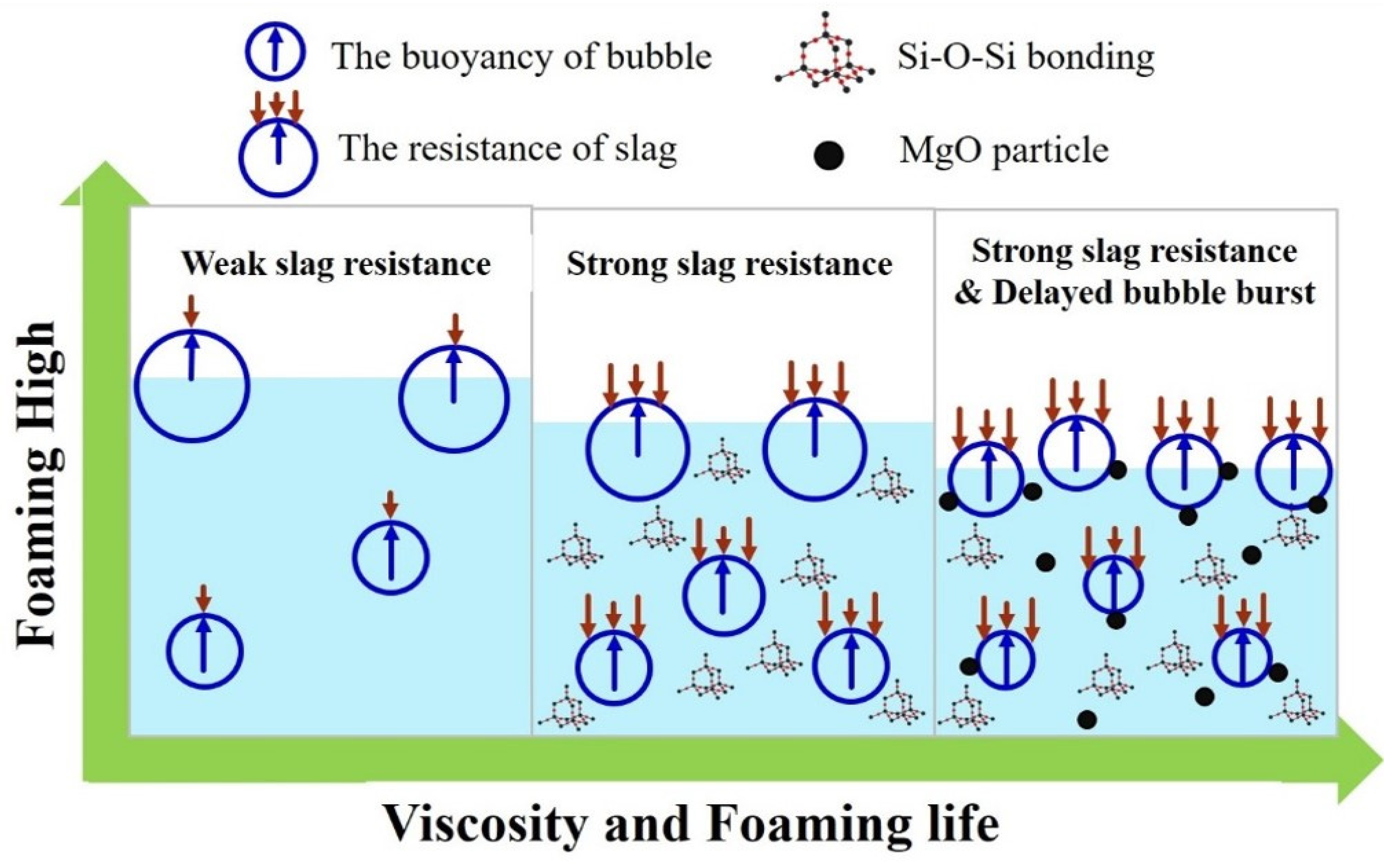
Foam stability was found to be influenced by two mechanisms-solid particles and liquid silica network bonding in the slag. The longest effective foaming life of 18.0 min was measured when both these mechanisms were acting. When only the silica network bonding took place, the effective foaming life was 6.2–7.7 min. In the ab-sence of these two factors, i.e., in a fully liquid slag with high basicity, the shortest foaming life, 2.0 min, was measured.

Author Contributions

Conceptualization, Y.-E.C. and C.-M.L.; Formal analysis, Y.-E.C.; Funding acquisition, W.W.; Investigation, J.-M.S., W.-T.C.; Methodology, Y.-E.C. and C.-M.L.; Project administration, W.W.; Supervision, W.W.; Validation, C.-M.L., J.-M.S. and W.-T.C.; Writing—Original draft, Y.-E.C. Writing—Review and editing, C.-M.L. and J.-M.S. All authors have read and agreed to the published version of the manuscript.

Funding

This work was supported by the China Steel Corporation, under projects numbered 109D402 and supported by the Ministry of Economic Affairs A+ Industrial innovative R&D program, Taiwan, under projects numbered 109D501.

Institutional Review Board Statement

Not applicable.

Informed Consent Statement

Not applicable.

Data Availability Statement

Data available in a publicly accessible repository.

Acknowledgments

The authors would like to thank the members of the Materials Science and Engineering at the National Chung Hsing University.

Conflicts of Interest

The authors declare no conflict of interest.

References

  1. Chen, H. The development of foaming slag steelmaking and its application in EAF. Shanghai Met. 1995, 17, 7–12. [Google Scholar]
  2. Kipepe, T.M.; Pan, X. Energy improvement in induction furnace using foaming slag with variation of carbon injection. J. Energy S. Afr. 2015, 26, 64–73. [Google Scholar] [CrossRef]
  3. Liang, F. Submerged-arc smelting with foamed slag in arc furnace and energy-saving. Hebei Metall. 1997, 97, 30–34. [Google Scholar]
  4. Pretorius, E.; Carlisle, R.J. Foamy slag fundamentals and their practical application to electric furnace steelmaking. Chem. Iron Steelmak. 1999, 26, 79–88. [Google Scholar]
  5. Wu, L.; Ek, M.; Song, M.; Sichen, D. The effect of solid particles on liquid viscosity. Steel Res. Int. 2011, 82, 388–397. [Google Scholar] [CrossRef]
  6. Luz, A.P.; Tomba Martinez, A.G.; López, F.; Bonadia, P.; Pandolfelli, V.C. Slag foaming practice in the steelmaking process. Ceram. Int. 2018, 44, 8727–8741. [Google Scholar] [CrossRef]
  7. Zhong, S.J. The dephosphorization and decarburation of the modern eaf steel making. Jiangxi Imetallurgy 2008, 28, 12–16. [Google Scholar]
  8. Feng, C.; Tang, J.; Gao, L.; Liu, Z.; Chu, M. Effects of CaO/SiO2 on viscous behaviors and structure of CaO-SiO2-11.00wt%MgO-11.00wt%Al2O3-43.00wt%TiO2 slag systems. ISIJ Int. 2019; 59, 31–38. [Google Scholar] [CrossRef] [Green Version]
  9. Arman, A.; Tsuruda, A.; Arma, L.; Takebe, H. Viscosity measurement and prediction of gasified and synthesized coal slag melts. Fuel 2017, 200, 521–528. [Google Scholar] [CrossRef]
  10. Ding, B.; Wang, H.; Zhu, X.; He, X.-Y.; Tan, Y.; Liao, Q. Prediction on crystallization behaviors of blast furnace slag in a phase change cooling process with corrected optical basicity. Fuel 2018, 223, 360–365. [Google Scholar] [CrossRef]
  11. Corbari, R.; Matsuura, H.; Halder, S.; Walker, M.; Fruehan, R.J. Foaming and the rate of the carbon-iron oxide reaction in slag. Metall. Mater. Trans. B 2009, 40, 940. [Google Scholar] [CrossRef]
  12. Tang, X.; Zhang, Z.; Guo, M.; Zhang, M.; Wang, X.-d. Viscosities behavior of CaO-SiO2-MgO-Al2O3 slag with low mass ratio of CaO to SiO2 and wide range of Al2O3 content. J. Iron Steel Res. Int. 2011, 18, 1–17. [Google Scholar] [CrossRef]
  13. Zhang, Y.; Fruehan, R.J. Effect of the bubble size and chemical reactions on slag foaming. Metall. Mater. Trans. B 1995, 26, 803–812. [Google Scholar] [CrossRef]
  14. Park, J.H. Structure-property correlations of CaO-SiO2-MnO slag derived from raman spectroscopy. ISIJ Int. 2012, 52, 1627–1636. [Google Scholar] [CrossRef] [Green Version]
  15. Kim, T.S.; Park, J.H. Structure-viscosity relationship of low-silica calcium aluminosilicate melts. ISIJ Int. 2014, 54, 2031–2038. [Google Scholar] [CrossRef] [Green Version]
  16. Park, Y.; Min, D.J. A structural study on the foaming behavior of CaO-SiO2-Mo (Mo = MgO, FeO, or Al2O3) ternary slag system. Metall. Mater. Trans. B 2017, 48, 3038–3046. [Google Scholar] [CrossRef]
  17. Heo, J.; Cho, J.; Park, H. Crystallization and vitrification behavior of CaO-SiO2-FetO-Al2O3 slag: Fundamentals to use mineral wastes in production of glass ball. J. Clean. Prod. 2019, 225. [Google Scholar] [CrossRef]
  18. Zhang, R.; Min, Y.; Wang, Y.; Zhao, X.; Jia, J.X.; Liu, C.J. Viscosity estimation of multicomponent slags of the CaO–SiO2–Al2O3–FexO system based on microstructure analysis. Energy Fuels 2020, 34, 8129–8138. [Google Scholar] [CrossRef]
  19. Retsinas, A.; Kalampounias, A.G.; Papatheodorou, G.N. Glass formation and raman spectra of CaO–SiO2 glasses towards the orthosilicate limit. J. Phys. Chem. Solids 2016, 99, 19–24. [Google Scholar] [CrossRef]
Figure 1. Factsage simulated phase diagram of foaming slag at 1500 °C.
Metals 11 00249 g001
Figure 2. Schematic diagram of (a) The Viscosity test (b) The foaming life test.
Metals 11 00249 g002
Figure 3. FactSage simulation of the solid phase fraction of different slag samples.
Metals 11 00249 g003
Figure 4. Amorphous glass phases of the samples (a) A1–A3 produced by water quenching; (b) A4 and A5 produced by water quenching still contain solid fractions.
Metals 11 00249 g004
Figure 5. Viscosity curve of the CaO-SiO2-MgO-5Al2O3-30FeO slags.
Metals 11 00249 g005
Figure 6. Foaming height and foaming life tests of A0–A6.
Metals 11 00249 g006
Figure 7. Analysis of the Raman spectral profiles and different Qn Raman shift values of each sample of slags, the MgO content is (a)5.7wt.%, (b) 7.4wt.%, (c) 9.6wt.%, (d) 11.5wt.%, (e) 13.6wt.%.
Metals 11 00249 g007
Figure 8. Influence of SiO2 content on Q2 + Q3 / Q0 + Q1 of liquid slag [14,15,19].
Metals 11 00249 g008
Figure 9. Influence of MgO content on the viscosity, foaming life, and solid fraction.
Metals 11 00249 g009
Figure 10. Schematic diagram of the foaming mechanism.
Metals 11 00249 g010
Table 1. Slag compositions of this study.
SamplesChemical Composition (wt.%)Solid Fraction
(1500 °C)
CaOSiO2MgOAl2O3FeO
A045.616.44.74.4290%
A135.823.65.74.830.10%
A235.1237.45.129.40%
A333.1229.65.3302.70%
A432.521.411.55.429.26.70%
A531.420.313.65.229.611.70%
Table 2. Viscosities of A0–A5 at a specific temperature and the Tcv.
SamplesViscosity (mPa.s)Critical Viscosity TemperatureSolid Fraction
(1500 °C)
1420 °C1460 °C1500 °C1550 °C
A069924722211495 (°C)0%
A154504743<1300 (°C)0%
A2474440381315 (°C)0%
A377727776411495 (°C)2.70%
A4--3631261575 (°C)6.70%
A5--1088567>1600 (°C) 11.70%
Table 3. Raman shift values of different structures and the Qn values.
StructuralQnRaman Shift (cm−1)Raman Assignments
[SiO4]Q0850~880With zero bridging oxygen
[Si2O7]Q1900~920With one bridging oxygen
[Si2O6]Q2950~1000With two bridging oxygen
[Si2O5]Q31045~1100With three bridging oxygen
Publisher’s Note: MDPI stays neutral with regard to jurisdictional claims in published maps and institutional affiliations.

