Article

Mechanism of Phosphorus Enrichment in Dephosphorization Slag Produced Using the Technology of Integrating Dephosphorization and Decarburization

1
School of Metallurgical Engineering, Anhui University of Technology, Ma’anshan 243002, China
2
Key Lab of Metallurgical Emission Reduction & Resources Recycling, Ministry of Education, Ma’anshan 243002, China
*
Author to whom correspondence should be addressed.
Metals 2021, 11(2), 216; https://doi.org/10.3390/met11020216
Submission received: 20 December 2020 / Revised: 19 January 2021 / Accepted: 21 January 2021 / Published: 26 January 2021

Abstract

:
In order to better understand and develop the technology of integrating dephosphorization and decarburization in a single converter (abbreviated as IDDSC), the relevant thermodynamic issues were discussed by calculation. Based on the thermodynamic calculation, the bridges between the phosphorus distribution ratio, temperature, and slag composition were constructed. Besides, the connections between the dephosphorization behavior and the microstructure of slag were also established by investigating four heats of hot metal smelt using IDDSC technology. As a result, the mechanism of phosphorus enrichment in the dephosphorization slag was revealed. Also, the results show that the dephosphorization efficiency increases gradually with increasing slag basicity. While the dephosphorization efficiency increases first and then decreases with the increase of FeO content in slag. There is a competition relationship between P2O5 and FeO in reacting with CaO and SiO2. When CaO/FeO is relatively high, not enough FeO is provided. Thus P2O5 is in priority to react with CaO and SiO2 through [3n + 2](CaO) + 2SiO2 + n(P2O5) = n(3CaO·P2O5)-2CaO·SiO2(s), generating P2O5-rich nC2S-C3P solid solution which promotes the removal of [P] from the hot metal. When CaO/FeO is relatively low, FeO competes over P2O5 in reacting with CaO and SiO2 through a(CaO) + b(SiO2) + c(FeO) = aCaO·bSiO2·cFeO(s), generating CaFeSiO4 instead of P2O5-rich solid solution. As a consequence, the slag with low CaO/FeO shows a poor dephosphorization ability.

1. Introduction

Phosphorus is a detrimental element that is very likely to cause cold brittleness in steel. Different steels have different requirements for the range of phosphorus content in final products, yet most steels require phosphorus content to be limited to less than 0.045% and the phosphorus in the hot metal should be removed as much as possible in terms of steel quality. The technology of integrating dephosphorization and decarburization in a single converter (abbreviated as IDDSC) [1,2,3] is a technology of transferring the task of dephosphorization pretreatment from outside the converter to inside the converter by the means of dividing the smelting process into dephosphorization stage and decarburization stage inside the converter. The flow chart of IDDSC technology is shown in Figure 1. At the beginning of the dephosphorization stage, various slagging agents are added into the converter furnace for the purpose of desilication and dephosphorization. At the end of dephosphorization stage, part of the dephosphorization slag is poured out and the remaining part is modified into decarbonization slag by adding proper slagging agents. It is evident that the IDDSC technology retains the technical characteristics of the duplex converters without suffering from the heat loss caused by the transport of semi-steel from the dephosphorization furnace to the decarbonization converter. Besides, the IDDSC technology saves an extra dephosphorization station outside the steelmaking converter. Hence, it is considered as an energy-saving, low-cost, and efficient technology which attracts a lot of attention from metallurgists [4].
The concept of integrating dephosphorization and decarburization in a single converter (IDDSC) was first put forward by Ogawa et al. It was named Multi-Refining Converter (abbreviated as MURC) and firstly tested in an 8-t experimental converter of Nippon Steel in 2001 [5,6]. It was reported that the IDDSC process may save 25% of slag volume [6]. Moreover, per ton of converter slag with a high temperature of around 1600 °C contains 1.5 GJ of heat energy. Assuming that the ratio of slag to hot metal is 1:100, then the heat loss is calculated to be reduced by 3750 kJ for per ton of hot metal, which indicates a big potential for savings on energy. For this reason, this idea was developed into a technology of integrating dephosphorization and decarburization in a single converter for energy saving and is widely applied in Oita, Yawata, Muroran, and Kimitsu Steelworks of the Nippon Steel Corporation [7,8,9,10,11]. Inspired by these typical examples, a similar IDDSC method named “Slag-Remaining + Double-Slag” was proposed by Shougang Corporation in China, and it has been successfully applied on a large scale in the affiliated Qianan Steelworks and Shouqin Steelworks [12]. The duplex slag process was optimized in a basic oxygen furnace (BOF). After optimization, the phosphorus content in steel at the end of the oxygen blowing stage was controlled to levels as low as 0.0042% [13]. Twenty heats of industrial trials were carried out in an 80-t converter of Wuhan Iron and Steel Corporation (abbreviated as WISCO) by employing the IDDSC technology, resulting in a mean dephosphorization efficiency of 91%, which is much higher than the efficiency (82%) obtained in the previous process [1]. Fang et al. [14] applied the IDDSC technology on a 120-t steelmaking converter and studied the influence of the basicity and oxidizability of slag on the dephosphorization performance. Fifty heats of industrial tests were carried out by Li et al. by employing IDDSC technology in a 100-t converter. With a rise in oxygen consumption ratio from 20–30% to 30–50% during the period of dephosphorization and [C] content limited in the range of 0.1–0.2%, the hit ratio of temperature increased from 86.3% to 92.3%, and the hit ratio of [P] content increased from less than 50% to 92.3%. This implies that the ability to control temperature and [P] content was significantly enhanced [3]. Wang et al. determined the optimal proportion for furnace burden and the optimal cut-off point between the dephosphorization stage and decarbonization stage [15], and investigated the slag forming route at both the dephosphorization and decarbonization stages during the production of medium phosphorus hot metal using IDDSC technology [2]. Although a lot of efforts have been put into developing IDDSC technology, most of the studies were focused on the technical aspect instead of the mechanism aspect.
To better understand the advantage and control principle of IDDSC technology, the IDDSC technology was deeply studied by a combination of technical analysis and mechanism exploration in the present paper. First, the essential points of operation for IDDSC technology were discussed based on the production practice. Then, the control target for the composition of dephosphorization slag in the IDDSC process was determined by thermodynamic calculation. Finally, the mechanism of phosphorus enrichment in the dephosphorization slag was studied by identifying and analyzing the typical dephosphorization slags in practical production. These researches provide an important reference for improving the IDDSC technology.

2. Technical Details for the IDDSC Process

The steelmaking converter used for this research has a nominal capacity of 70 t. At the beginning, 56–63 t of hot metal and 10–14.5 t of scrap steel are charged into the converter as the raw material for steelmaking. The converter is equipped with an oxygen lance coupled with a four-hole nozzle, and the oxygen supply intensity is in the range of 3.3–3.6 m3/(t·min), with a blowing flow rate of 16,000 m3/h and a blowing pressure of 0.75–0.85 MPa. The Mach number is 1.98 and the outlet diameter is 42 mm. Three double annular slot gas supply elements are used for blowing argon gas from the bottom. The argon flow rate ranges from 90 to 120 m3/h and the blowing pressure ranges from 0.2 to 0.4 MPa. The refractory of the converter lining is MgO–C brick. The composition and temperature of the hot metal are shown in Table 1.
The key of the IDDSC technology is the proper control of the lance position and blowing flow. Their control scheme is shown in Figure 2. A total amount of 2000–2600 kg of lime, 1000–1300 kg of light-burned dolomite, and 800–1000 kg of ore were added during the whole process of converter steelmaking. At the beginning of the dephosphorization stage when the oxygen lance is ignited, both the lance position and blowing flow rate are adjusted to a high level, accompanied with light burnt dolomite (3/4) and ore (1/3) addition, in order to form slag quickly and keep an atmosphere of high oxidizability. After slag formation, both the lance position and blowing flow rate are lowered to remove silicon and manganese from the hot metal. At the end of the dephosphorization stage before deslagging, both the lance position and blowing flow rate are elevated again to generate more FeO in the slag. In this way, the processes of dephosphorization and foaming slag were promoted, and the fully foamed slag is more easily poured out. After deslagging, lime (2/3) and light burnt dolomite (1/4) are added to modify the remaining dephosphorization slag into decarbonization slag. At this point, a high blowing flow rate is necessary to accelerate slag formation and this point is considered to be the beginning of the decarbonization stage. After slag formation, blowing flow rate is decreased to a low level for decarbonization. One minute later, the remaining lime and ore are selectively added based on the actual smelting process, aimed at achieving the fine and accurate adjustment of slag composition. After decarbonization for about 10 min, the decarbonization reaction weakens gradually. At this point, the lance position is elevated properly to accelerate slagging and avoid rephosphorization caused by slag drying. At the end of the decarbonization stage, the lance position is lowered while the blowing flow rate is increased to intensify the stirring action for the purpose of ensuring the homogenization of the composition and temperature of the molten steel.

3. Thermodynamic Calculations for Dephosphorization

According to the previous literatures, the equilibrium distribution of phosphorus between the slag and hot metal follows a certain pattern as shown in Equation (1) [16].
lg ( % P ) / a P = 2.5 lg ( % T F e ) + 0.0715 ( % C a O ) + 0.25 ( % M g O ) + 7710.2 / T 8.55
where a P represents the activity of [P] in the hot metal, TFe represents the total amount of iron in slag.
a P can be calculated by Equations (2) and (3):
a P = f P [ % P ]
lg f P = e P C [ % C ]
where f P represents the activity coefficient of [P], e P C represents the interaction coefficient between [C] and [P]. e P C can be obtained by Equation (4) as proposed by Tsukihashi [17].
e P C = 105.1 T + 0.0723
The phosphorus partition ratio between the slag and hot metal, LP, is defined as:
lg L P = lg ( % P ) / [ % P ]
Through a series of mathematical transformation, the equation for phosphorus distribution ratio (LP) can be obtained as below:
lg L P = 2.5 lg ( % T F e ) + 0.0715 ( % C a O ) + 0.25 ( % M g O ) + 7710.2 / T 8.55 + ( 105 . 1 / T + 0 . 0723 ) [ % C ]
The slag is mainly composed of MgO, CaO, SiO2, iron oxides, and other minor components such as MnO, P2O5, and Al2O3. Assuming that all iron oxides exist in the form of FeO, the total amount of the minor components is 15%, (MgO) content in slag is 8.0%, [C] content in the hot metal is 3.8%, then Equation (6) can be converted into Equation (7).
lg L P = 2.5 lg ( % F e O ) + 0.0715 B 1 + B ( 77 72 / 56 ( % F e O ) ) + 8109.58 / T 8.4
where B is the basicity of slag, expressed as:
B = (%CaO)/(%SiO2)
According to Equation (7), the relationship between phosphorus distribution ratio (LP), temperature (T), slag basicity (B), and FeO content can be described in Figure 3. With the increase of FeO content, the phosphorus distribution ratio first increases and then decreases. And FeO content should be controlled in the range of 20–25% to obtain optimal dephosphorization efficiency. As seen in Figure 3a, the phosphorus distribution ratio shows an increasing tendency with the increase of basicity. As seen in Figure 3b, the phosphorus distribution ratio decreases notably with elevated temperature. This is consistent with the general viewpoint that low temperature facilitates dephosphorization of the hot metal [18,19]. Based on the discussion above, in order to obtain a good dephosphorization performance, FeO content in slag should be controlled in the range of 20–25%, the slag basicity should be kept at a high level, while the temperature should be lowered as much as possible in the premise of satisfying fluidity.

4. Sampling and Analysis

In order to verify the calculated thermodynamic rules and to deduce the corresponding mechanism, four heats of the hot metal under the action of typical slag composition were produced by employing IDDSC technology. During the period of production, hot metal samples before and after dephosphorization were taken using a cylindrical immersion sampler and quenched in cold water quickly. To calculate the dephosphorization efficiency, the element concentrations in these hot metal samples were examined by inductively coupled plasma mass spectrometry (ICP-MS, Thermo Electron Corporation, Waltham, MA, USA, IRIS intrepid II). Slag samples were dipped using a long molybdenum rod and quenched in cold water quickly at the end of the dephosphorization stage. Each slag sample was divided into three parts. One part is examined by X-ray fluorescence (XRF, Thermo Scientific, ARLAdvant’X Intellipower™ 3600) to determine chemical composition. Another part is evaluated by X-ray diffraction to identify phase type. The X-ray diffraction (XRD) is performed on a diffractometer (Bruker, D8ADVANCE, Cu Kα radiation) between 5° and 85° (2θ) by steps of 0.01°. The tube voltage is set as 60 kV and the current is set as 60 mA. The left part is prepared as metallographic samples by a series of operations, such as mounting, grinding, polishing, and gold-spraying. The metallographic samples were evaluated under a scanning electron microscope (SEM, JSM-6490LV, Japan) equipped with energy dispersive spectrometry (EDS, INCA, OXFORD, England).

5. Experimental Results

5.1. Compositions of Slag and Hot Metal

The compositions of the hot metal before and after dephosphorization are shown in Table 2. The composition of slag detected by XRF analysis and the dephosphorization efficiency calculated based on ICP analysis results are shown in Table 3. The dephosphorization efficiency ( η P ) is calculated by the following Equation:
η P = [ P ] B - [ P ] A [ P ] B × 100 %
where [P]B represents the [P] content in hot metal before dephosphorization and [P]A represents the [P] content in hot metal after dephosphorization.
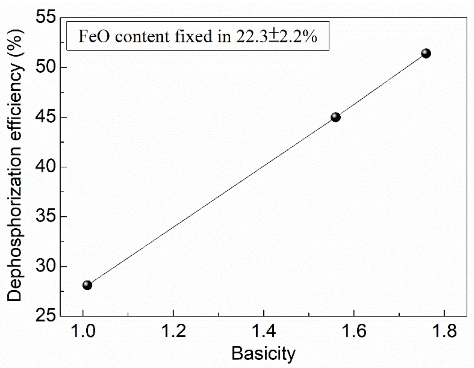
As seen in Table 3, the slags in Heat 2 and Heat 3 with appropriate FeO content (in the range of 20–25% according to the thermodynamic calculation in Section 3 and relatively high basicity (1.56 and 1.76, respectively) have high dephosphorization efficiency (45% and 51.4%, respectively). The slag in Heat 1 with relatively low basicity (1.01) has a low dephosphorization efficiency (28.1%). The slag in Heat 4 with relatively high FeO content (31.4%) also possesses a low dephosphorization efficiency (22.9%). It should be noted that the average P content in the slags was calculated to be in the range of 1–2%. No CaF2 was added in the dephosphorization slags to avoid the generation of poisonous gases such as AlF3(g), SiF4(g), or CaF2(g) [20].

5.2. Microsturcture of Dephosphorizaiton Slag

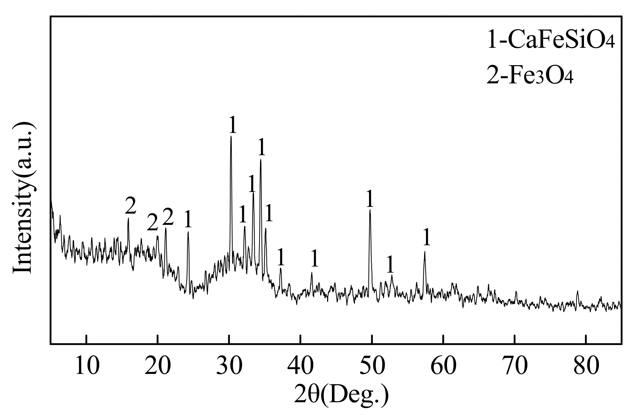
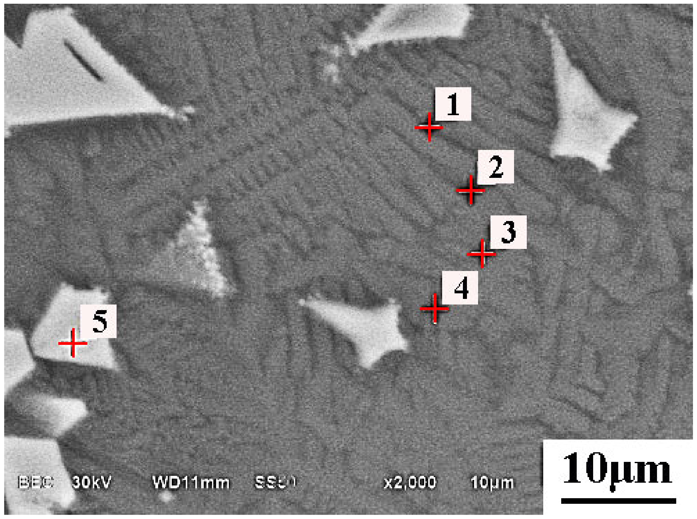
The XRD pattern of the slag with a relatively low basicity in Heat 1 after dephosphorization is shown in Figure 4. It shows that the dephosphorization slag consists of a great deal of CaFeSiO4 and a little Fe3O4. The microscopic morphology of the slag and the corresponding EDS results are shown in Figure 5 and Table 4, respectively. The slag is composed of a massive grey coralloidal phase and a few white blocky phases. Combining the XRD analysis result with the fact that the grey phase is mainly composed of Ca, Si, Fe, and O, the grey phase can be identified as CaFeSiO4. The phosphorus content keeps stable in the grey phase and in the average phosphorus range (1–2%) of slag. This implies that the phosphorus element is evenly distributed in the grey phase without enrichment. The white phase is mainly composed of Fe and O, thus is identified as Fe3O4 combined with the XRD analysis result.
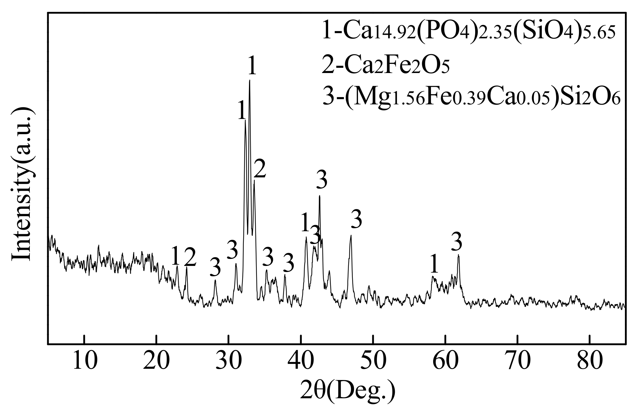
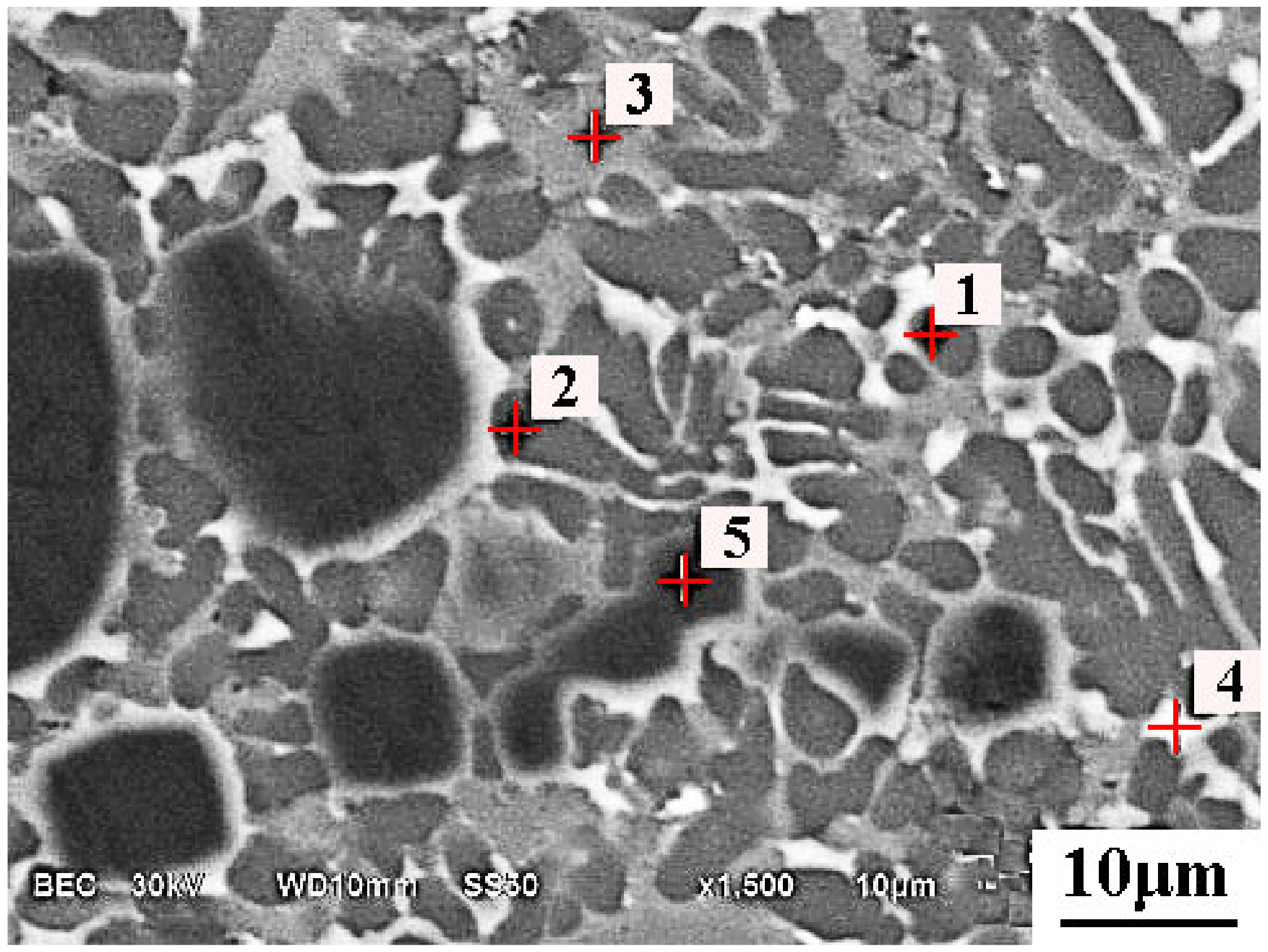
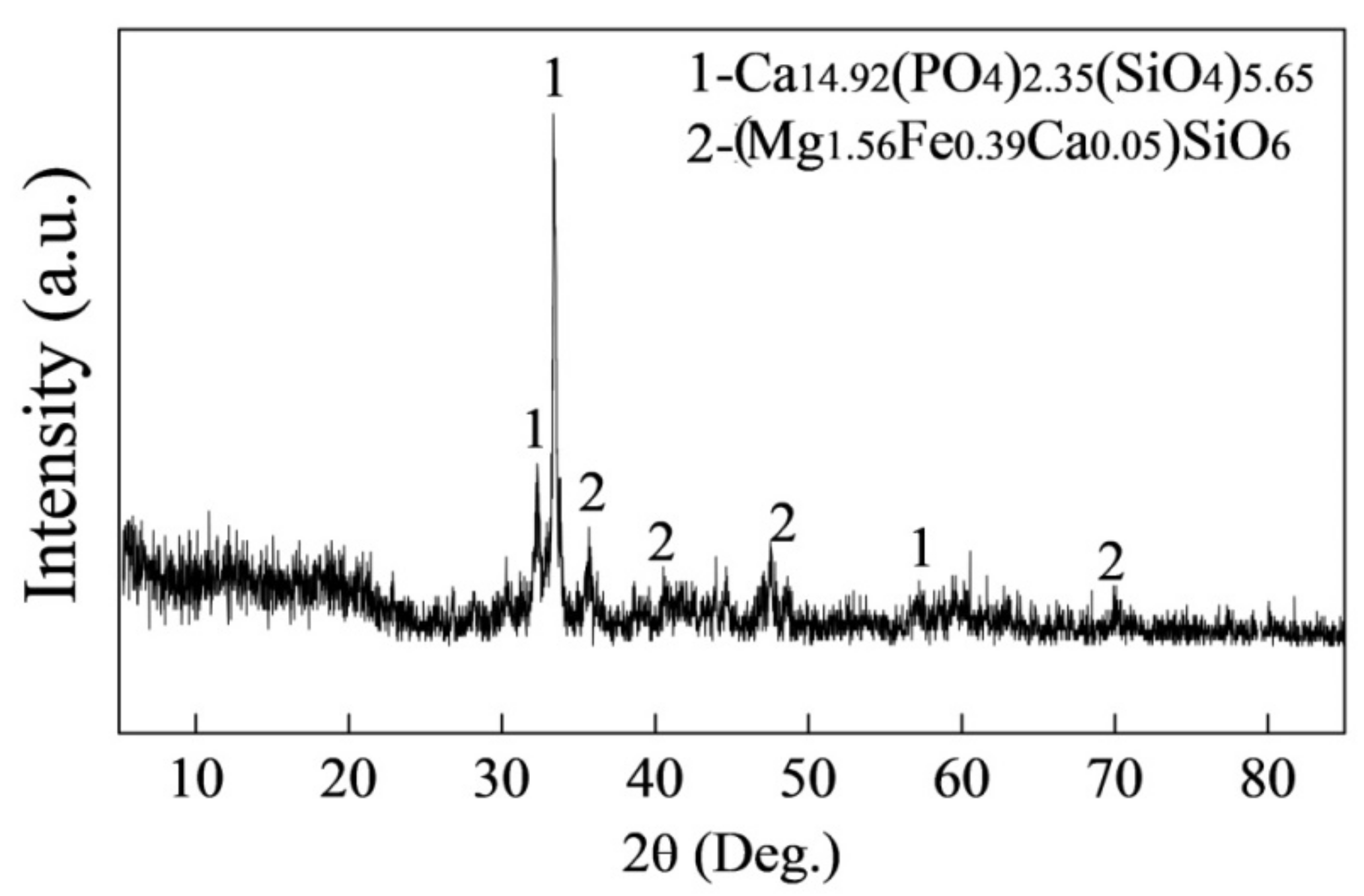
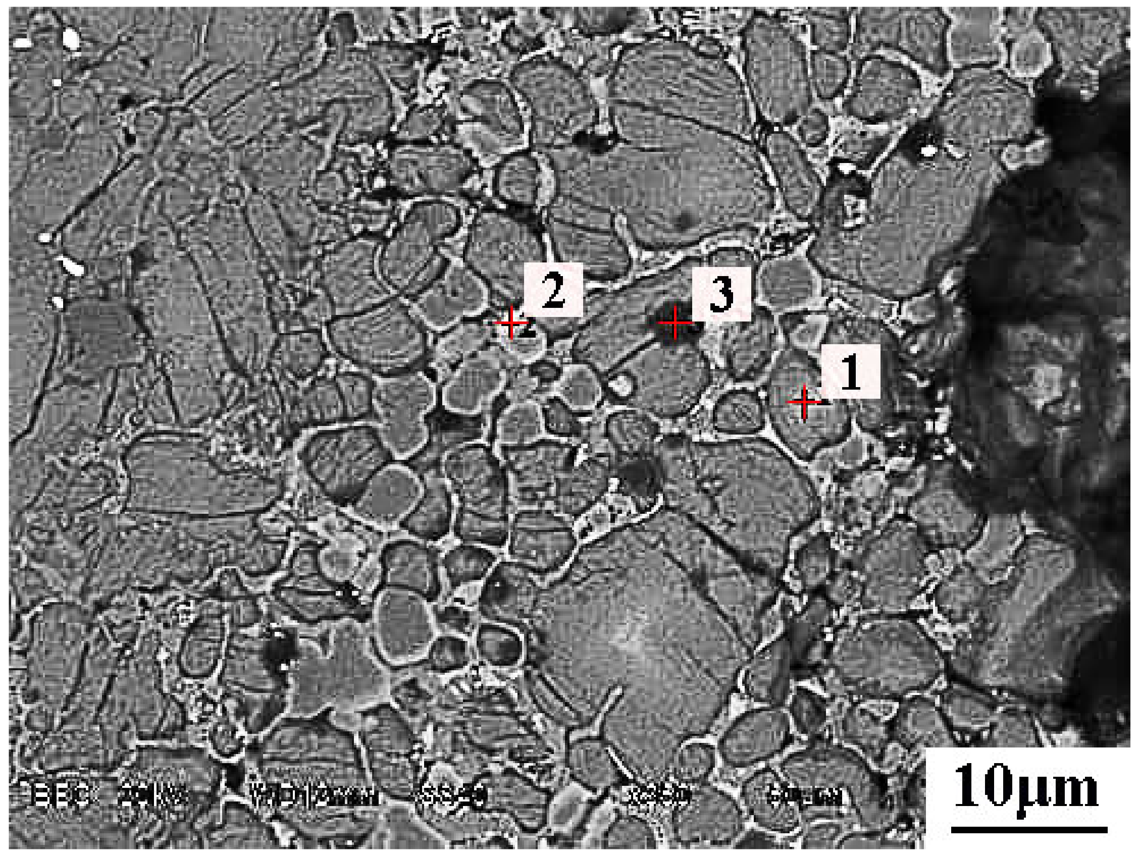
The XRD pattern of the slag with proper FeO content and relatively high basicity in Heat 2 is shown in Figure 6. It can be seen that the slag contains Ca14.92(PO4)2.35(SiO4)5.65 (abbreviated as nC3P C2S), Ca2Fe2O5, and (Mg1.56Fe0.39Ca0.05)Si2O6. The microscopic morphology of the slag and the corresponding EDS results are shown in Figure 7 and Table 5, respectively. The slag is composed of the light grey dendrites, the dark grey phase embedded in the light grey phase, and a small quantity of black phase. The dark grey phase is mainly composed of Ca, Si, and O elements. It should be noted that the phosphorus content in the dark grey phase is higher than the average value (1–2%). This implies that phosphorus enriches in the dark grey phase. Hence, the dark grey phase is recognized as P-rich nC3 C2S. The light grey dendrite is mainly composed of Ca, Fe, and O elements, and, thus, is identified as Ca2Fe2O5 combined with the XRD analysis result. The most obvious trait of the dark phase lies in its high concentration of Mg. This indicates that the dark phase is (Mg1.56Fe0.39Ca0.05)Si2O6 combined with the XRD analysis result.
The XRD pattern of the slag with similar FeO content and higher basicity in Heat 3 (compared with that in Heat 2) is shown in Figure 8. It shows that the slag consists of nC3P C2S and (Mg1.56Fe0.39Ca0.05)Si2O6. The microscopic morphology of the slag and the corresponding EDS results are shown in Figure 9 and Table 6, respectively. The slag is composed of dark grey phase, light grey phase, and a little black phase. The dark grey phase is mainly composed of Ca, Si, and O elements. In addition, the dark grey phase contains 3.8% of phosphorus, which is much higher than the average value (1–2%) in slag. Therefore, the dark grey phase is recognized as nC3P C2S. The light grey phase is identified as (Mg1.56Fe0.39Ca0.05)Si2O6 based on its trait of containing a high concentration of Mg and Fe. The black phase mainly contains Ca and O and is thus thought to be CaO.
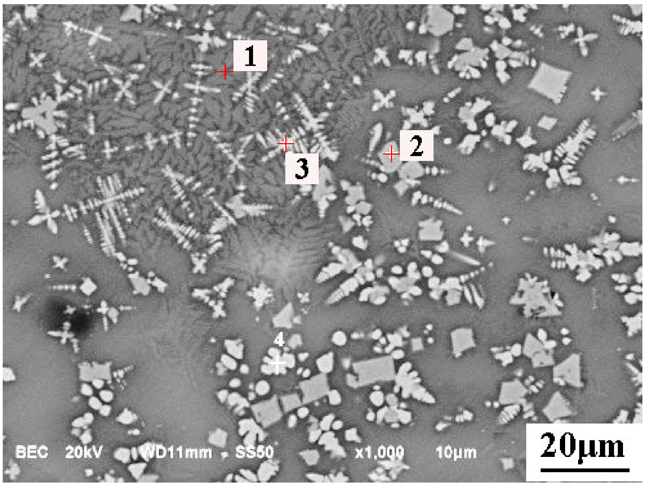
The XRD pattern of the slag containing relatively high FeO concentration in Heat 4 is shown in Figure 10. It can be seen that the slag consists of CaFeSiO4 and Fe3O4. The microscopic morphology of the slag and the corresponding EDS results are shown in Figure 11 and Table 7, respectively. The slag is composed of light grey coralloidal phase, white dendritic or blocky phase, and grey slag matrix. The grey phase is mainly composed of Ca, Si, Fe, and O, thus is identified as CaFeSiO4. The white phase is mainly composed of Fe and O, thus is identified as Fe3O4.

6. Discussions

The dephosphorization slags in Heats 1–3 contain similar FeO content but have quite different basicity. When the FeO content is fixed within the scope of 22.3 ± 2.2%, the relationship between dephosphorization efficiency and slag basicity can be established and plotted in Figure 12. The dephosphorization efficiency shows an increasing tendency with the rise of slag basicity, which is consistent with the calculated laws in Section 3. This indicates that relatively high basicity is an essential condition for good dephosphorization performance.
As shown in Table 3, the dephosphorization slag containing a high concentration of FeO out of the optimal scope (20–25% as mentioned in Section 3) in Heat 4 has a low dephosphorization efficiency of 22.9%. This infers that too much FeO may inhibit the dephosphorization reaction.
Based on the molecular theory of molten slag, [P], [Si], [Mn], and [C] in the hot metal will be oxidized by FeO in slag at the interface between the slag and hot metal, as expressed below:
5(FeO) + 2[P] = 5[Fe] + (P2O5)
2(FeO) + [Si] = 2[Fe] + (SiO2)
(FeO) + [Mn] = [Fe] + (MnO)
(FeO) + [C] = [Fe]+ CO(g)
[Si], [Mn], and [C] have a strong reductibility and thus compete with [P] to combine with the oxygen of FeO within slag by Reactions (11), (12), and (13), respectively. Therefore, the oxidation of [Si], [Mn], and [C] take place during the dephosphorization process, weakening the dephosphorization reaction and, thus, leading to an obvious reduce in [Si], [Mn], and [C] content as shown in Table 2.
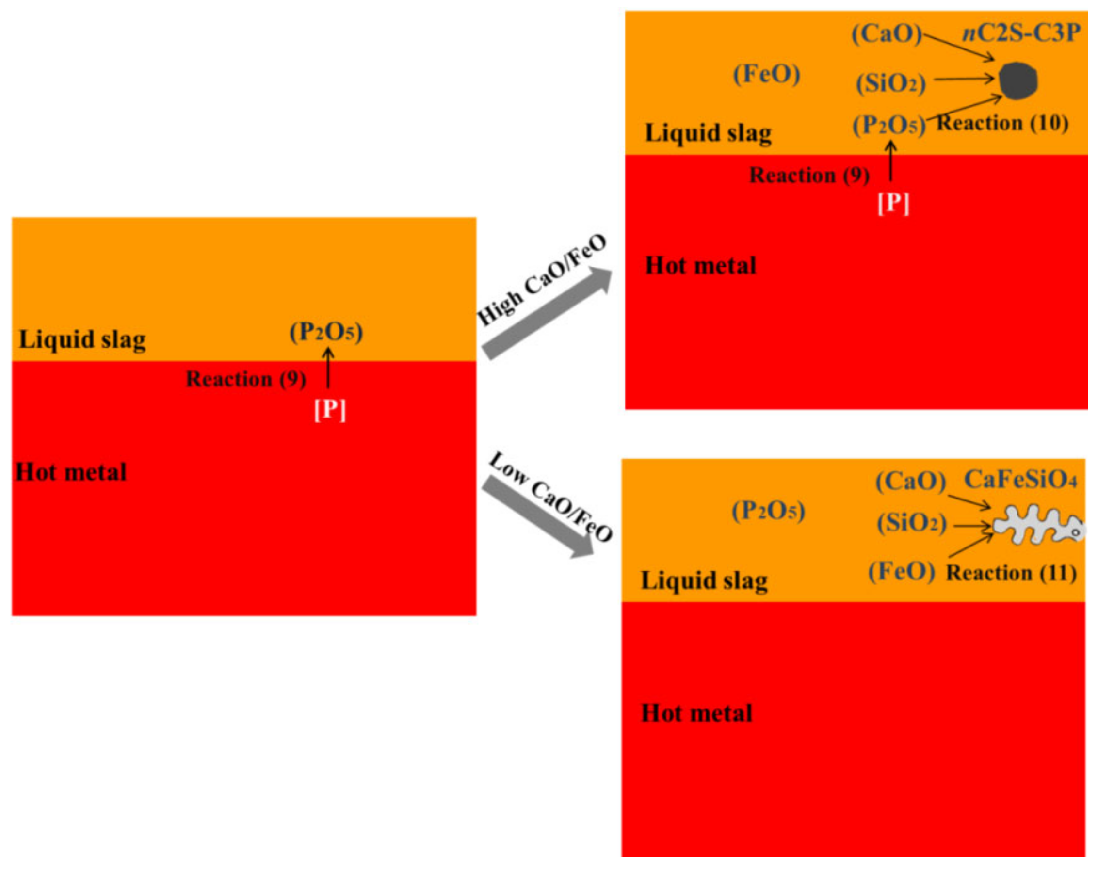
The generated P2O5 is very likely to gather in nC2S-C3P solid solution by the means of combining with CaO and SiO2 in slag, as expressed by Formula (14). This process decreases the activity of P2O5 in the liquid part of slag, whereby promoting the progress of Reaction (10) which further facilitates the removal of [P] from the hot metal to slag.
[3n + 2](CaO) + 2SiO2 + n(P2O5) = n(3CaO·P2O5)-2CaO·SiO2(s)
For Heats 2 and 3 with appropriate FeO content and relatively high basicity (CaO/FeO is about 1.8), the dephosphorization efficiency was relatively high (45% and 51.4%, respectively) and P2O5-rich nC2S-C3P (Ca14.92(PO4)2.35(SiO4)5.65) was detected in the dephosphorization slag. This proves the deduction mentioned above that the generation of nC2S-C3P derived from Reaction (14) facilitates the removal of [P] from the hot metal to slag.
For Heat 1 with relatively low basicity and Heat 4 with relatively high FeO, no P2O5-rich nC2S-C3P is formed in the slag and, thus, the dephosphorization efficiency is low (28.1% and 22.9%, respectively). The low basicity or high FeO content of the slag in Heat 1 and 4 mean a relatively low CaO/FeO ratio (1.03 and 0.73, respectively). Under this condition, FeO plays a leading role between CaO and FeO. Hence, the massive FeO is very likely to react with CaO and SiO2 to generate aCaO·bSiO2·cFeO solid solution as expressed by Reaction (15). This process consumes the CaO and SiO2 that could have combined with P2O5 by Reaction (13). For this reason, generation of nC2S-C3P is inhibited. This conjecture can be proved by the fact that CaFeSiO4 (aCaO·bSiO2·cFeO) and Fe3O4 were detected instead of Ca14.92(PO4)2.35(SiO4)5.65 (nC2S-C3P) in the slags of Heat 1 and Heat 4.
a(CaO) + b(SiO2) + c(FeO) = aCaO·bSiO2·cFeO(s)
Based on the discussions above, the interaction mechanism can be deduced, as shown in Figure 13. Firstly, [P] in hot metal is oxidized by FeO in slag to generate P2O5. There is a competition relationship between the generated P2O5 and the already existing FeO attributed to their similar thermodynamic property. When CaO/FeO is relatively high (that is, FeO content is low), FeO loses in the competition. As a consequence, P2O5 instead of FeO combines with CaO and SiO2 to generate nC2S-C3P solid solution, accelerating the removal of [P] from the hot metal. When CaO/FeO is relatively low (that is, FeO content is high), FeO wins in the competition. Therefore, FeO instead of P2O5 combines with CaO and SiO2 to generate CaFeSiO4, resulting in poor dephosphorization performance of slag.

7. Conclusions

In the present paper, technical details for the IDDSC process were introduced, the relationship between phosphorus distribution ratio (LP), temperature (T), and slag composition was established via thermodynamic calculations. In addition, the enrichment mechanism of P in solid solution was deduced. Through research, some key conclusions were drawn as below:
  • The relationship between phosphorus distribution ratio (LP), temperature (T), and slag composition can be presented as:
    lg L P = 2.5 lg ( % FeO ) + 0.0715 R 1 + R ( 77 72 / 56 ( % FeO ) ) + 8109.58 / T 8.4
  • In order to obtain optimal dephosphorization efficiency, the FeO content in slag should be limited in the range of 20–25%, the slag basicity should be elevated to a high level, while the temperature should be lowered as much as possible in the premise of ensuring required fluidity.
  • For the dephosphorization slag containing proper FeO content and having relatively high basicity, nC2S-C3P solid solution generates and gathers phosphorus, which promotes the removal of phosphorus from the hot metal. For the dephosphorization slag having a relatively low basicity or containing a relatively high FeO, no P2O5-rich nC2S-C3P generates and, thus, the dephosphorization efficiency is low.
  • There is a competition relationship between P2O5 and FeO in reacting with CaO and SiO2. When CaO/FeO is relatively high, P2O5 is in priority to combine with CaO and SiO2 to generate nC2S-C3P solid solution by [3n + 2](CaO) + 2SiO2 + n(P2O5) = n(3CaO·P2O5)-2CaO·SiO2(s), which facilitates the removal of [P] from the hot metal. When CaO/FeO is relatively low, FeO instead of P2O5 is more likely to react with CaO and SiO2 to generate CaFeSiO4 by a(CaO) + b(SiO2) + c(FeO) = aCaO·bSiO2·cFeO(s), resulting in a poor dephosphorization performance of slag.

Author Contributions

Conceptualization, L.C. and J.L.; methodology, L.C. and H.X.; software, H.X.; validation, Y.W., Y.X., and C.L.; formal analysis, C.L.; investigation, L.C.; resources, J.L.; data curation, L.C.; writing—original draft preparation, L.C. and H.X.; writing—review and editing, L.C. and Y.W.; visualization, C.L.; supervision, J.L.; project administration, J.L.; funding acquisition, Y.X. All authors have read and agreed to the published version of the manuscript.

Funding

This research was funded by the National Natural Science Foundation and Steel Joint Research Fund of China BaoWu Steel Group Co., LTD, grant number U1960110, as well as the National Natural Science Foundation of China, grant number 52074003 and grant number 52074001.

Data Availability Statement

The data presented in this study are available on request from the corresponding author. The data are not publicly available due to the confidentiality agreement that we signed with the cooperative steelworks.

Conflicts of Interest

The authors declare no conflict of interest.

References

  1. Zhou, Y.Y.; Yu, C.H.; Xu, J.B.; Feng, J. Experimental study on hot metal dephosphorizing pretreatment and direct steelmaking process in converter. Steelmaking 2004, 20, 40–43. [Google Scholar]
  2. Wang, X.B.; Feng, M.X.; Zou, Z.S.; Zhao, G.G.; Liu, Z.X. Slag forming route and dephosphorization of BOF dephosphorizing pretreatment and direct Steelmaking. Iron Steel 2009, 44, 23–26. [Google Scholar] [CrossRef]
  3. Li, J.; Huang, B.C.; Fang, Y.R.; Chen, B.Y.; Liu, L. Research on hot metal dephosphorizing pretreatment and direct steelmaking process in 100 t converter. Iron Steel 2010, 45, 36–39. [Google Scholar]
  4. Liu, L. Technological progress in converter steelmaking. Steelmaking 2000, 40, 1–5. [Google Scholar]
  5. Ogawa, Y.; Yano, M.; Kitamura, S.; Hirata, H. Development of the continuous dephosphorization and decarburization process using BOF. Tetsu-to-Hagane 2001, 87, 21–28. [Google Scholar] [CrossRef] [Green Version]
  6. Ogawa, Y.; Yano, M.; Kitamura, S. Development of the continuous dephosphorization and decarburization process using BOF. Steel Res. Int. 2003, 74, 70–76. [Google Scholar] [CrossRef]
  7. Iwasaki, M.; Matsuo, M. Change and development of steelmaking technology. Nippon Steel Tech. Rep. 2011, 391, 88–93. [Google Scholar]
  8. Kumakura, M. Advances in the refining technology and the future prospects. Nippon Steel Tech. Rep. 2012, 394, 4–11. [Google Scholar]
  9. Iwasaki, M.; Matsuo, M. Improvement of hot metal dephosphorization technique. Nippon Steel Tech. Rep. 2012, 394, 26–32. [Google Scholar]
  10. Hashimoto, T.; Iiboshi, H.; Kume, K. Improvement in production capacity at Oita Works. Nippon Steel Tech. Rep. 2012, 394, 84–90. [Google Scholar]
  11. Kobayashi, M.; Isobe, K.; Arai, M. Technical progress in steelmaking and casting for special bar and wire steel at Muroran Work. Nippon Steel Tech. Rep. 2012, 394, 119–124. [Google Scholar]
  12. Li, H.B.; Lu, Y.C.; Zhu, G.H.; Wang, X.H. Development of ‘Slag-Remaining+Double-Slag’ BOF steelmaking technology in Shougang Co. In Advances in Molten Slags, Fluxes, and Salts: Proceedings of the 10th International Conference on Molten Slags; Springer: Cham, Switzerland, 2016; pp. 1177–1184. [Google Scholar]
  13. Yang, X.; Sun, F.M.; Yang, J.L.; Liu, F.; Cheng, K.S.; Wang, J.H. Optimization of low phosphorus steel production with double slag process in BOF. J. Iron Steel Res. Int. 2013, 20, 41–47. [Google Scholar] [CrossRef]
  14. Fang, Y.R.; Hang, B.C. Study on dephosphorization pretreatment process in 120t converter. In Proceedings of the 17th National Steelmaking Academic Conference, Hangzhou, China, 15–17 May 2013; pp. 112–118. [Google Scholar]
  15. Wang, X.; Zou, Z.S. Theoretics study on demarcation point of dephosphorization pretreatment and direct steelmaking process in converter. China Metall. 2007, 17, 10–13. [Google Scholar]
  16. Healy, G.W. New look at phosphorus distribution. J. Iron Steel Inst. 1970, 208, 664–668. [Google Scholar]
  17. Tsukihashi, F.; Nakamura, M.; Orimoto, T.; Sano, N. Thermodynamics of phosphorus for the CaO-BaO-CaF2-SiO2 and CaO-Al2O3 systems. Tetsu-to-Hagané 1990, 76, 1664–1671. [Google Scholar] [CrossRef] [Green Version]
  18. Liao, P.; Hou, Z.W.; Qin, Z.; Zhang, X.Z.; Qiu, S.T. Experimental study of double slag combined blowing converter blowing dephosphorization process. Iron Steel 2013, 48, 30–36. [Google Scholar]
  19. Zhou, C.G.; Li, J.; Wu, H. Study on the temperature of first deslagging of double slag dephosphorization in converter. Iron Steel 2014, 49, 24–28. [Google Scholar]
  20. Wang, W.; Sun, K.; Liu, H.T. Effects of different aluminum sources on morphologies and properties of ceramic floor tiles from red mud. Constr. Build. Mater. 2020, 241. [Google Scholar] [CrossRef]
Figure 1. Flow chart of integrating dephosphorization and decarburization in a single converter (IDDSC) process.
Metals 11 00216 g001
Figure 2. Control scheme of IDDSC process.
Metals 11 00216 g002
Figure 3. Changes of phosphorus distribution ratio with FeO content (a) temperature fixed at 1623 K, various basicity; (b) basicity fixed at 1.8, various temperatures.
Metals 11 00216 g003
Figure 4. XRD pattern of dephosphorization slag in Heat 1.
Metals 11 00216 g004
Figure 5. Scanning electron microscope (SEM) micrograph (backscattered electron) of the dephosphorization slag in Heat 1.
Metals 11 00216 g005
Figure 6. XRD pattern of dephosphorization slag in Heat 2.
Metals 11 00216 g006
Figure 7. SEM micrograph (backscattered electron) of the dephosphorization slag in Heat 2.
Metals 11 00216 g007
Figure 8. XRD pattern of dephosphorization slag in Heat 3.
Metals 11 00216 g008
Figure 9. SEM micrograph (backscattered electron) of the dephosphorization slag in Heat 3.
Metals 11 00216 g009
Figure 10. XRD pattern of dephosphorization slag in Heat 4.
Metals 11 00216 g010
Figure 11. SEM micrograph (backscattered electron) of the dephosphorization slag in Heat 4.
Metals 11 00216 g011
Figure 12. Relationship between dephosphorization efficiency and slag basicity.
Metals 11 00216 g012
Figure 13. Interaction mechanism between the slag and hot metal for dephosphorization.
Metals 11 00216 g013
Table 1. Compositional content and temperature of the hot metal (wt.%).
[C][Si][Mn][P][S]Temperature of Hot Metal (K)
4.30–4.600.50–0.600.25–0.350.120–0.1400.001–0.0031593–1613
Table 2. Compositions of hot metal before and after dephosphorization.
Heat No.Sampling PositionCSiMnPSDephosphorization Efficiency (%)
1Before dephosphorization4.370.550.300.1250.02828.1%
After dephosphorization2.780.010.040.08990.024
2Before dephosphorization4.420.540.320.1360.02645%
After dephosphorization2.510.010.0600.07480.020
3Before dephosphorization4.560.570.270.1320.02351.4%
After dephosphorization2.860.010.0700.06410.019
4Before dephosphorization4.520.530.250.1370.02328.1%
After dephosphorization2.980.010.0600.1060.020
Table 3. Slag composition and dephosphorization efficiency.
Heat No.SiO2CaOFeOMgOMnOP2O5BasicityDephosphorization Efficiency (%)
125.025.224.53.68.62.71.0128.1
222.835.720.14.25.04.81.5645
320.936.820.76.53.33.51.7651.4
417.522.931.43.85.72.21.3122.9
Table 4. Energy dispersive spectrometry (EDS) analysis results (wt.%) of dephosphorization slag in Heat 1 corresponding to Figure 5.
Collected PositionColorCaSiFePMgMnO
Point 1Grey21.514.214.51.741.76.739.7
Point 2Grey21.014.414.61.761.86.639.8
Point 3Grey21.013.714.91.592.67.738.5
Point 4Grey20.613.215.41.522.47.539.4
Point 5White3.541.737.0-2.29.446.2
Table 5. EDS analysis results (wt.%) of dephosphorization slag in Heat 2 corresponding to Figure 7.
Collected PositionColorCaSiFePMgMnO
Point 1Dark grey43.029.248.042.60-0.8136.29
Point 2Dark grey38.858.729.202.601.191.1338.31
Point 3Light grey45.180.8015.500.48-4.0034.04
Point 4Light grey35.402.0617.990.761.672.0240.1
Point 5Black10.212.2716.76-31.883.1135.77
Table 6. EDS analysis results (wt.%) of dephosphorization slag in Heat 3 corresponding to Figure 9.
Collected PositionColorCaSiFePMgMnO
Point 1Dark grey38.112.3-3.8--45.8
Point 2Light grey-5.030.5-33.86.124.6
Point 3Black56.23-----27.32
Table 7. EDS analysis results (wt.%) of dephosphorization slag in Heat 4 corresponding to Figure 11.
Collected PositionColorCaSiFePMgMnO
Point 1Light grey14.4813.2218.131.881.748.935.51
Point 2White2.411.5932.03-1.498.2721.71
Point 3White4.673.3245.360.581.918.3126.18
Point 4White1.721.1654.99-1.678.3723.48
Publisher’s Note: MDPI stays neutral with regard to jurisdictional claims in published maps and institutional affiliations.