Article

Grain Structure, Crystallographic Texture, and Hardening Behavior of Dissimilar Friction Stir Welded AA5083-O and AA5754-H14

by
Mohamed Mohamed Zaky Ahmed
1,2,*,
Sabbah Ataya
2,3,
Mohamed Mohamed El-Sayed Seleman
2,
Tarek Allam
2,4,
Naser Abdulrahman Alsaleh
3 and
Essam Ahmed
2
1
Department of Mechanical Engineering, College of Engineering at Al Kharj, Prince Sattam Bin Abdulaziz University, Al Kharj 16273, Saudi Arabia
2
Department of Metallurgical and Materials Engineering, Faculty of Petroleum and Mining Engineering, Suez University, Suez 43512, Egypt
3
Department of Mechanical Engineering, College of Engineering, Al Imam Mohammad Ibn Saud Islamic University, Riyadh 11432, Saudi Arabia
4
Steel Institute (IEHK), RWTH Aachen University, D-52056 Aachen, Germany
*
Author to whom correspondence should be addressed.
Metals 2021, 11(2), 181; https://doi.org/10.3390/met11020181
Submission received: 31 December 2020 / Revised: 16 January 2021 / Accepted: 18 January 2021 / Published: 20 January 2021
(This article belongs to the Special Issue Advanced Welding Technology in Metals)

Abstract

:
This work investigated the effect of friction stir welding (FSW) tool rotation rate and welding speed on the grain structure evolution in the nugget zone through the thickness of the 10 mm thick AA5083/AA5754 weldments. Three joints were produced at different combinations of FSW parameters. The grain structure and texture were investigated using electron backscattering diffraction (EBSD). In addition, both the hardness and tensile properties were investigated. It was found that the grain size varied through the thickness in the nugget (NG), which was reduced from the top to the base in all welds. Reducing the rotation rate from 600 rpm to 400 rpm at a constant welding speed of 60 mm/min reduced the average grain size from 33 µm to 25 µm at the top and from 19 µm to 12 µm at the base. On the other hand, the increase of the welding speed from 20 mm/min to 60 mm/min had no obvious effect on the average grain size. This implied that the rotation rate was more effective in grain size reduction than the welding speed. The texture was the mainly simple shear texture that required some rotations to obtain the ideal simple shear texture. The hardness distribution, mapped for the nugget zone, and the parent alloys indicated a diffused softened welding zone. The heating effect of the pressure and rotation of the pin shoulder and the heat input parameter (ω/v) on the hardness value of the nugget zone were dominating. Tensile stress-strain curves of the base alloys and that of the FSWed joints were evaluated and presented. Moreover, the true stress-true strain curves were determined and described by the empirical formula after Ludwik, and then the materials strengthening parameters were determined. The tensile specimens of the welded joint at a revolution speed of 400 rpm and travel speed of 60 mm/min possessed the highest strain hardening parameter (n = 0.494).

1. Introduction

Aluminum alloys have remained the prime selection in producing various components in many industries like aerospace, automotive, and shipbuilding because of their perfect strength to weight ratio [1,2,3,4,5]. AA5000-series alloys are characterized by a good strength-to-weight ratio and an appropriate corrosion resistance. However, they are difficult to join by conventional fusion welding techniques because of their dendritic structure, which seriously weakens the mechanical properties. Solid-state welding processes are appropriate joining for either similar or dissimilar aluminum alloys [6]. Resistance spot welding is considered one of the dominant solid-state welding processes in automotive constructions [7,8]. However, the use of a continuous welding line process instead of weld spots leads to higher structural stiffness and better crash performance [9]. Friction stir welding (FSW) of the AA5000 series represents a promising technique to obtain defect-free and sound joints, either in similar [10] and dissimilar [11,12,13] welding combinations. FSW can also be used effectively for the welding of different types of materials [14,15,16,17], and the same principle of FSW can be used for the development of metal matrix composites [18,19,20,21,22]. In FSW, a non-consumable rotating tool induces a stirring action until the tool shoulder contacts the top surface of the sheets with a given plunge depth, generating a large amount of frictional heat [23]. As the tool moves along the welding line, the blanks are joined through a solid-state process, owing to the severe plastic strain and the metal mixing across the weld. The weld zone undergoes a solid-state process promoted by the frictional heat between the wear-resistant welding tool and the materials to be joined. The plasticized zone is further extruded from the tool advancing side to the retreating side during its steady traversing along the joint line [24]. FSW process parameters influence the final joint quality and performance, including traverse welding speed; tool rotational speed, geometry, and shape; blank thickness; heat input; applied force; tilt angle; specimen preparation; sheet-rolling direction; plates/sheets metallurgical history. It has been demonstrated that, among process parameters, the tool rotational speed and traverse welding speed have a strong effect on heat generation, heat dissipation, and cooling rate. Hence, the microstructure and texture, and mechanical properties evolution of the FSW joints are significantly affected by traverse welding speed and tool rotational speed values [6,11,24,25,26]. For this reason, an accurate choice of the FSW process parameters and of the tool material and geometry is required. In fact, the joint mechanical properties can be optimized by increasing the tool rotational speed or by decreasing the traverse welding speed [27,28]. The excessive agglomerations and joints defects are produced when the high strength aluminum alloy on the advancing side (AS) of AA5052/AA5J32 is placed because of material flow limitation [29]. Both material flow and joint quality are more dependent on the FSW conditions and their effects on heat input and temperature distribution in weld nugget, regardless of base material (BM) placement [30]. During FSW, the heat generation is controlled by tool rotation and welding speed due to the material plastic flow [30,31,32]. However, very high rotation speeds lead to macroscopic defects because of the excessive heat input [24,33]. Due to FSW, three different metallurgical zones are usually recognized, namely, nugget zone (NZ), thermomechanically affected zone (TMAZ), and heat-affected zone (HAZ) [34]. In the NZ, the metal is in direct contact with the pin being continuously stirred during the passage of the rotating tool, thus creating the necessary strong bond between the two metals under the welding. Fast thermomechanical heating (peak temperature may reach 0.6 to 0.95 TM) and cooling occur, and they favor the occurrence of dynamic recrystallization (DRX) phenomena, generating fine grain structures in the form of onion rings [34,35]. From a microstructural viewpoint, the NZ is generally characterized by a fine or even very-fine equiaxed grained structure, as mentioned in [34]. In the TMAZ, the microstructure experiences a significant grain morphology and size modification. Because of the insufficient deformation strain, DRX does not occur in the TMAZ. In the third zone, HAZ, the materials are subjected to thermal cycles with no plastic deformation, and the microstructure has the same grain structures as the parent material (BM) [6,25]. The transients and gradients in strain, strain rate, and temperature are inherent in the thermomechanical cycles of FSW, which control and shape the characteristic microstructural zones of a typical FSW joint. During FSW, material flows in a complex, vortex-like pattern around the pin from the advancing side to the retreating side [14]. The high stacking fault energy metallic materials, such as aluminum, enhance the dynamic recovery (DRV) to occur during the hot working process [36,37]. As the DRV rate is increased, low-angle grain boundaries (LABs) are formed to minimize the dislocation forest/multiplication by the rearrangement of most of the dislocations. In DRX, new, dislocation-free grains form at high energy sites, such as prior grain boundaries, deformation band interfaces, or boundaries of newly recrystallized grains [38,39]. All the herein mentioned mechanisms of formation for sub-grains and grains (TMAZ) and recrystallized fine grains (NZ) are always also dependent on the material’s initial metallurgical conditions and are subject to different FSW process and tool parameters. Thus, the aim of this work was to examine the effect of FSW tool rotation rate and the welding speed on the grain structure, texture, and mechanical properties of AA5083/AA5754. In this work, three FSWed AA5083/AA5754 joints (J1: 600 rpm and 60 mm/min, J2: 400 rpm and 60 mm/min, and J3: 400 rpm and 20 mm/min) were produced. Through the thickness of the produced joints, the grain structure and texture were investigated using EBSD. In addition, both the hardness distribution and tensile properties measurements were investigated. A full description of materials and experimental procedures is in Section 2. The results and discussion are presented in Section 3. The conclusion drawn from this work is in Section 4.

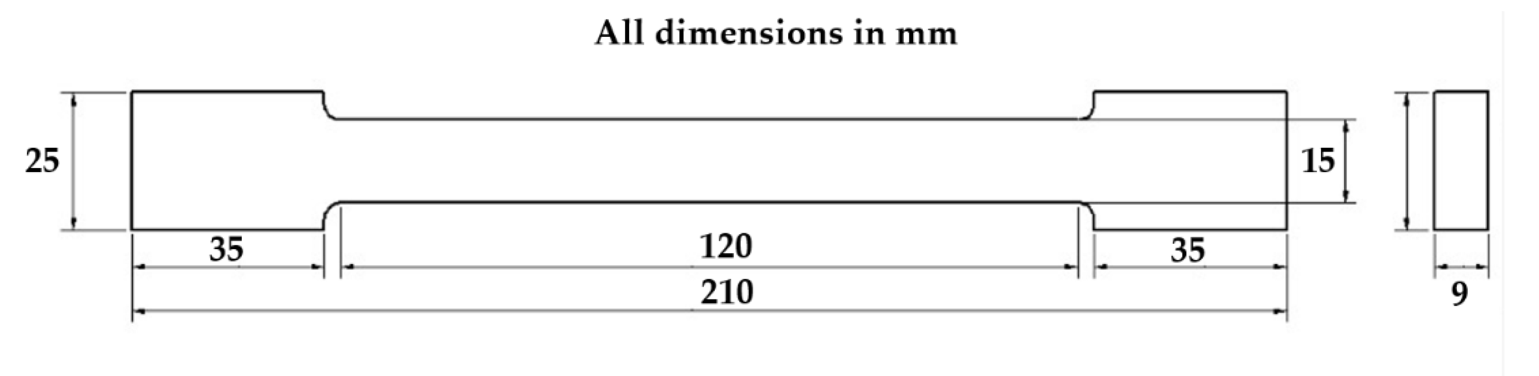
2. Materials and Methods

The materials under investigation are the aluminum alloys AA5083-O (AlMg4.5Mn0.6) and AA5754-H14 (AlMg3.1). More details on the full chemistry of both AA5083-O and AA5754-H14 are found in our previous work [11]. The temper designated “O” in AA5083-O state means in the annealed condition, which is applied to increase subsequent alloy workability. While “H14” in AA5754-H14 states that strain hardened-1/2 hard condition. The hardness values of AA5083-O and AA5754-H14 are 68 and 74 HV, respectively; the hardness values were measured using 1 Kg load and averaged out of 10 measurements. Vickers hardness tester machine (HWDV-75, TTS Unlimited, Osaka, Japan) was used. The alloys were supplied in the form of rolled plates of 10 mm thick. The FSW butt joints were designed to be 200 mm × 110 mm on each side. Figure 1 represents a schematic for the FSW process, showing all the basic elements and the movement direction. Friction stir welding was carried to produce three different joints between the two aluminum alloys with FSW rotation rates and welding traverse speeds combination as follows: J1 (600 rpm-60 mm/min), J2 (400 rpm-60 mm/min), and J3 (400 rpm-20 mm/min). The FSW tool used was made from the H13 tool steel that was heat treated and tempered to 54 HRC (hardness Rockwell C) hardness. The joints after production were section perpendicular to the welding direction (WD) and prepared to read the optical macrographs. For the EBSD investigation, samples from the top and bottom of the weld Nugget were cut. These samples were then mechanically polished and subsequently electropolished with a solution of 30% nitric acid in methanol for 60 s at 14 V and −15 °C. FEI Quanta FEG 250 Field Emission Gun Scanning Electron Microscope (FEGSEM), FEI company (Hillsboro, OR, USA), equipped with a Hikari EBSD camera controlled by EDAX-OIM7.3 (EDAX Inc. Mahwah, NJ, USA) analysis software, was used for EBSD data acquisition and post processing. To evaluate the changes in the mechanical properties due to the FSW process, the base alloys, as well as the FSWed joints, were tested using tensile and hardness testing. Vickers macro-hardness tests were performed on the transverse cross-sections with an interspacing distance of 2 mm using a test load of 1 kg force and a dwell time of 15 s. The tensile test properties of the welded stir zone and transverse flat tensile specimens were used. Tensile samples were machined perpendicular to the FSW direction to the dimensions, as shown in Figure 2. The specimen’s dimensions agree with the DIN EN10002-1 2001(D) standards. Tensile tests were carried out at room temperature and at a quasi-static strain rate of ε 0.001 s−1 using the tensile testing machine Instron Type 4210, Norwood, MA, USA.

3. Results and Discussion

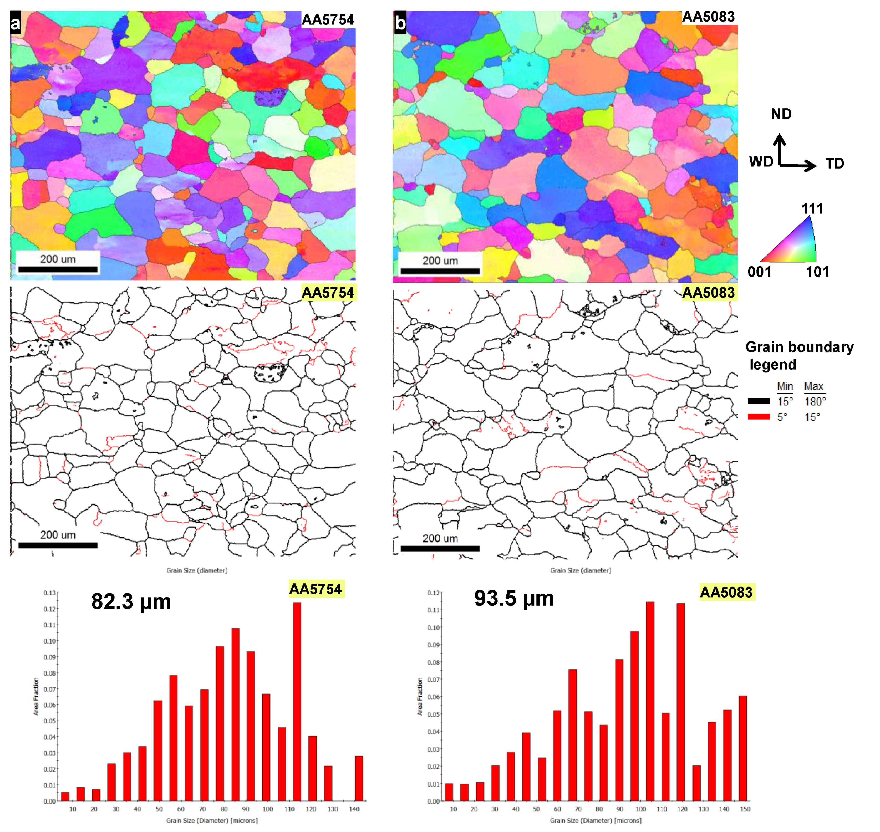
3.1. Microstructural Features of the Base Aluminum Alloys

Figure 3 shows the inverse pole figure coloring maps (a, b), their corresponding grain boundary maps with high angle boundaries (HABs) > 15° in black lines and low angle boundaries (LABs) from 5° to <15° in red lines, and the grain size distribution charts for the as-received aluminum alloys AA5754 and AA5083. The microstructures of the AA5754 and AA5083 Al-alloys in the as-received conditions revealed a recrystallized grain structure. The presented maps of both alloys showed random and fully recrystallized grain structures without pronounced textures, as indicated by the color-code legend of grain orientations and the low density of low angle grain boundaries. The average grain diameters of AA5754 and AA5083 alloys were measured to be 82.3 with a standard deviation of 29 and 93.5 µm with a standard deviation of 34, respectively, as can be seen from the corresponding distribution of grain diameters. The results of EBSD measurements of the as-received conditions demonstrated insignificant differences in the initial grain structure of the base alloys.

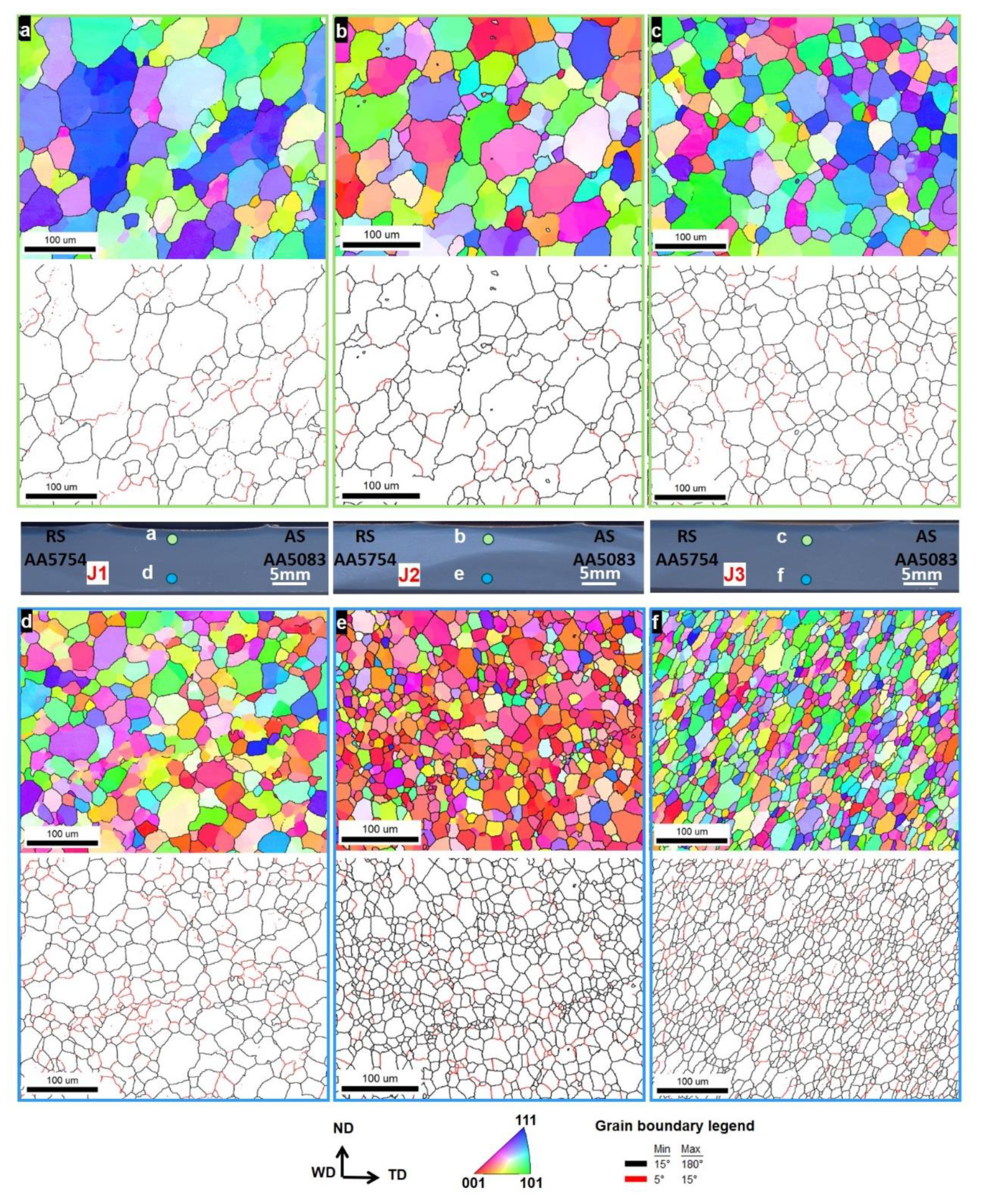
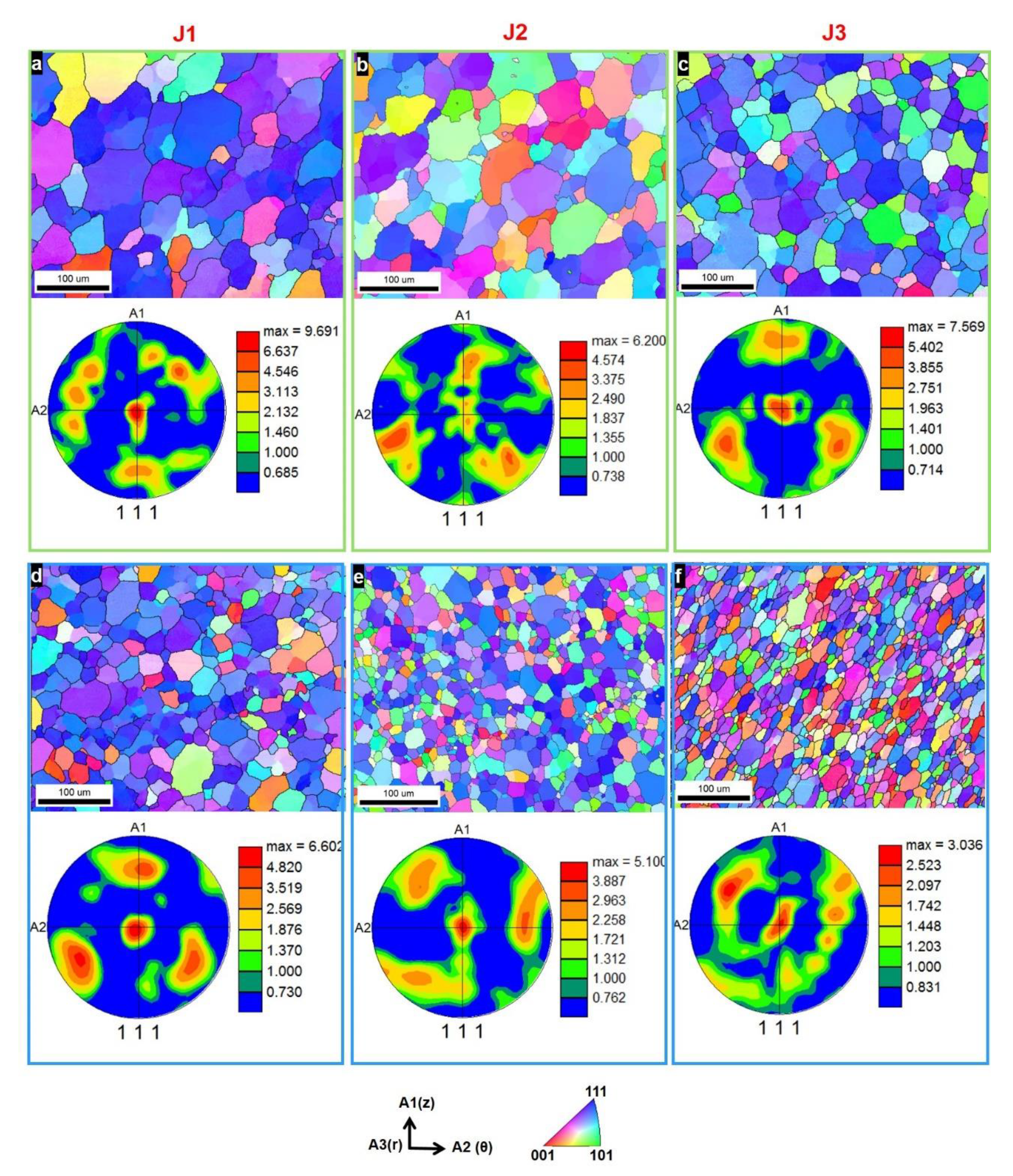
3.2. Microstructural Features of the FSWed Dissimilar AA5083-AA5754 Joints

Figure 4 shows a collage of the macro- and micrographs that reveal the main characteristics of the grain structures for the dissimilar AA5754-AA5083 joints welded using different combinations of rotation rates and travel speeds of the FSW tool. The macrographs in the middle point out to the locations (Figure 4), where the EBSD measurements were performed using 1 µm step size. Two locations (one at the top and the other at the bottom) were investigated in the NG zone, almost along the vertical centerline for each joint. Generally, the top locations in the NG zones (a, b, and c) showed always larger grain structures than those developed at the corresponding bottom locations (d, e, and f). This can be attributed to the high heat generated at the top surface due to the effect of both the shoulder and the pin, while near the bottom of the NG is only affected by the pin with lower heat experienced [12,24,32,40,41]. Furthermore, it is clear that the grain sizes in the NG zones showed a dependency on the rotation and travel speeds as well. As can be seen, the grain sizes of J1 manufactured at 600 rpm–60 mm/min (Figure 4a,d) were coarser than their counterparts of J2 manufactured at 400 rpm–60 mm/min (Figure 4b,e), indicating a grain refining effect induced by the decrease in the rotation rate of the tool from 600 to 400 rpm. On the other hand, the decrease in the welding traverse speed from 60 mm/min to 20 mm/min at a constant rotation rate of 400 rpm had not resulted in a significant effect on the grain structure and the average grain size, as can be observed from Figure 4c,f. The variation in grain sizes from the top to the bottom locations through the thickness in the NG zones can be explained by the higher heat experienced at the top regions of the joints due to the friction-induced heat caused by the contact between the work-piece and the tool shoulder and pin during FSW, while the bottom regions are only affected by the pin and accordingly experience a lower heat [42,43]. Another factor that promotes a variation in heat from the top to the bottom of the NG zones is the thick section of the welded plates, which contribute to a higher cooling capacity during FSW [44]. It is also expected that the variation in heat from the top to the bottom through the thickness of NG zones can be affected by the rotation and travel speeds. Accordingly, higher heat input is excepted for the higher rotation speed and slower travel speed, which reflects the grain structure evolution in J1 that experiences the highest heat input (coarse grain structure) and in J2 that is exposed to the lowest heat input (finer grain structure). The obtained results here are in agreement with that reported in work conducted by Ahmed et al. [24] for the FSW of the thick section AA6082. They reported a significant reduction in the grain size towards the bottom part of the weld NG, which they attributed to the lower heat input experienced at the lower part due to the only pin effect relative to the top part of the NG, which was affected by both the pin and the shoulder of the tool. Besides, there was a significant reduction in the grain size by decreasing the heat input through the reduction of the tool rotation rate. The grain-size distributions represented in grain diameter based on the measured grain areas in the NG zones of J1, J2, and J3 are shown in Figure 5. The same data-sets represented in Figure 3 were utilized to calculate the grain-size distributions at the top locations (a, b, and c) and at the bottom locations (d, e, and f) for J1, J2, and J3, respectively. It was remarked that the average measured grain diameters in the NG zones at the top locations varied from 33, 25, to 24.5 µm, and at the bottom locations, changed from 19, 12, to 11.8 µm for J1, J2, and J3, respectively. Obviously, the grain sizes in the NG zones at the bottom locations were more than two times finer than those counterparts at the top locations. It should be noted here that the effect of reducing the tool rotation rate was more effective in controlling the grain size than increasing the traverse speed. Reducing the tool rotation rate from 600 rpm to 400 rpm resulted in a reduction of the average grain size at the top from 33 µm to 25 µm and at the bottom from 19 µm to 12 µm. On the other hand, decreasing the traverse speed from 60 mm/min to 20 mm/min almost did not affect the grain size parameters. In both cases, the average grain size was almost similar at the top locations, about 25 µm, and at the bottom locations, about 12 µm. In terms of grain orientation of the maps presented in Figure 4 and obtained at the top and the bottom locations of the NG from each weld, it could be considered randomly orientated with mixed <001> red, <101>green, and <111> blue orientations. It should be mentioned here that the data presented in Figure 4 is the as-collected data in which there was a difference between the FSW reference frame (TD, ND, WD) and the actual shear reference frame (θ, z, r), as quantitatively determined in a detailed study by Ahmed et al. [45,46] for the methodology to be applied to align the FSW reference frame with the shear reference frame to obtain the real FSW texture and orientations. Figure 6 shows the inverse pole figure (IPF) coloring maps with their corresponding (111) pole figures for the same data presented in Figure 4 after applying the required rotations to align the FSW reference frame with the shear reference frame. Now the IPF maps (Figure 6a−f) were dominated by the <111> blue orientations due to the alignment of the <111> poles with shear plan normal (r). In terms of texture, it could be observed from the (111) pole figures (PFs) that the texture was strong texture with up to 10 times random and was mainly of simple shear texture. The (111) PF of the J1 joint (Figure 6a,d) had the strongest texture with 10 times random at the top and 7 times random at the bottom of the NG. This could be attributed to the high amount of deformation experienced due to the high tool rotation rate (600 rpm) and the fast welding speed (60 mm/min). The (111) PF of the J2 joint (Figure 6b,e) had slightly relatively less strong texture with 6 and 5 times random at the top and bottom of the NG, respectively. The (111) PF of the J3 joint (Figure 6c,f) showed strong texture with 7 times random at the top and only 3 times at the bottom. This indicates the effect of the FSW parameters on the strength of the texture components. In all cases, the textures were of the simple shear, which is the main type of texture reported in the NG of FSWed aluminum alloys [45,46].

3.3. Mechanical Properties

Vickers macro-hardness distribution profiles on the transverse cross-sections of the joints produced by FSW are shown in Figure 7. Figure 7a–c show the hardness maps for the three joints (J1, J2, and J3); it can be noted that the FSW-affected zones were diffusing and extended to a width of 22 mm at the bottom of the butt joint and increased to reach around 40 mm at the upper surface due to the effect of the friction and the pressure applied by the rotating shoulder to the surface of the joint.
The conical shape of the SZ and HAZ was more obvious at the joints with low ω/v values of 10 (J1: 600 rpm and 60 mm/min). The FSW nuggets showed the lowest hardness values due to the heat input concentrated in these regions, causing softening of the stirred regions of the joined materials. At both applied rotational speeds (400 and 600 rpm), the lower hardness region took place in the upper surface of the joints at the lowest travel speed (20 mm/min) and then appeared in the lower half of the cross-section at the highest travel speed (60 mm/min). This statement confirmed the softening effect of the friction and pressure of the pin shoulder on the upper surface of specimens [47].
Figure 8 represents the engineering tensile stress-strain curves of the base alloys AA5083 and AA5754 and the FSWed dissimilar joints. Flow behavior of the Al–Mg alloys of the series AA5XXX have been investigated at quasi-static and high strain rate ranges [48,49] and showed similar serration in the flow curves, which are related to the so-called Portevin-Le Chatelier effect [49,50,51]. This effect is due to successive pinning and unpinning of the moving dislocations by the solute atoms. The base aluminum alloys show typical stress-strain curves with moderate hardening, followed by a wide plastic strain range up to the ultimate tensile stress, followed by a slow decrease of stress value up to fracture.
Table 1 includes the tensile properties of the tested specimens of the welded joints compared with that of the base alloys. The tensile sample of the FSWed joint at the revolution of 400 rpm and travel speed of 60 mm/min (J2: 400-60) showed similar behavior to the base materials, except that the short plastic strain range was lower than the base alloys. This showed higher tensile stress than the base alloy AA5083 from the beginning of the plastic strain region till its ultimate tensile stress value (224 MPa) and decreased till fracture at a total elongation of 23%. Relating the ultimate tensile value of this joint to the ultimate tensile value of the base alloy AA5083 resulted in a welding efficiency of 96%. The other two tensile samples of the FSWed joints ((J1: 600-60) and (J3: 400-20)) were early fractured at strains of 5.5% and 4.3%, respectively, before reaching the ultimate tensile value. This behavior was due to the presence of some welding defects, such as tunnels or pores [52]. However, the yield stress of the tensile sample taken from these joints (J1: 600-60 and J3: 400-20) was comparable with the yield stress of the base alloy AA5083. The increased strength and the soundness of the sample (J2: 400-60) were related to the lowest heat input value, as shown in Table 1, where its heat index value was one third that of the sample J3: 400-20 and one half of the sample J1: 600-60.
To describe the flow behavior of the tensile stress-strain curves ( σ   ε ) of the materials under investigation, the engineering curves were transferred to the true stress-true strain ( σ f φ ) up to the ultimate point by these formulas: true stress σ f = σ   ( 1 + ε ) and true strain φ = l n   ( 1 + ε ) .
There are many published models describing the flow behavior of metallic materials [53,54,55]. The description model can be selected depending on the suitability for the specific material and the test conditions. The model simplicity for application, represented in the low number of model parameters, is a factor helping the spread of some models. The flow curves of the tested samples were described using the empirical formula relating the flow stress ( σ f ) and true strain ( φ ) after Ludwik [56]:
σ f =   σ o + k   ( φ ) n
where initial flow stress ( σ o ) is the flow stress at the plastic strain of φ = 0, k is a material parameter, and n is the material strengthening parameter.
Figure 9 shows the description of the plastic flow curves of the base alloys AA5754 and AA5083 and the FSWed joints using the Ludwik formula. It can be seen that the selected empirical model described the curves very well. The materials parameters (k and n) of the base alloys were relatively low due to the combination of the flow curve of the higher strengthening rate region at the beginning of the flow curve and the moderate hardening in the steady-state region up to the end of the flow curve. The samples of the joints welded at the conditions 400-20 and 600-60 showed higher strengthening parameter (n) and higher material parameter (k) than the base alloys due to the early fracture of the samples, leading to shortening of the flow curves, especially the lower strengthening rate region at the end of the curve. However, the FSWed joint using pin revolution of 400 rpm and a travel speed of 60 mm/min showed the highest strengthening parameter (n = 0.494) with a moderate k value of 413. The tensile flow parameters of the flow curves are summarized in Table 2. In the three joints (J1, J2, and J3), the fracture mechanism was ductile mode with very clear dimple features, and it is fully characterized in [9].

4. Conclusions

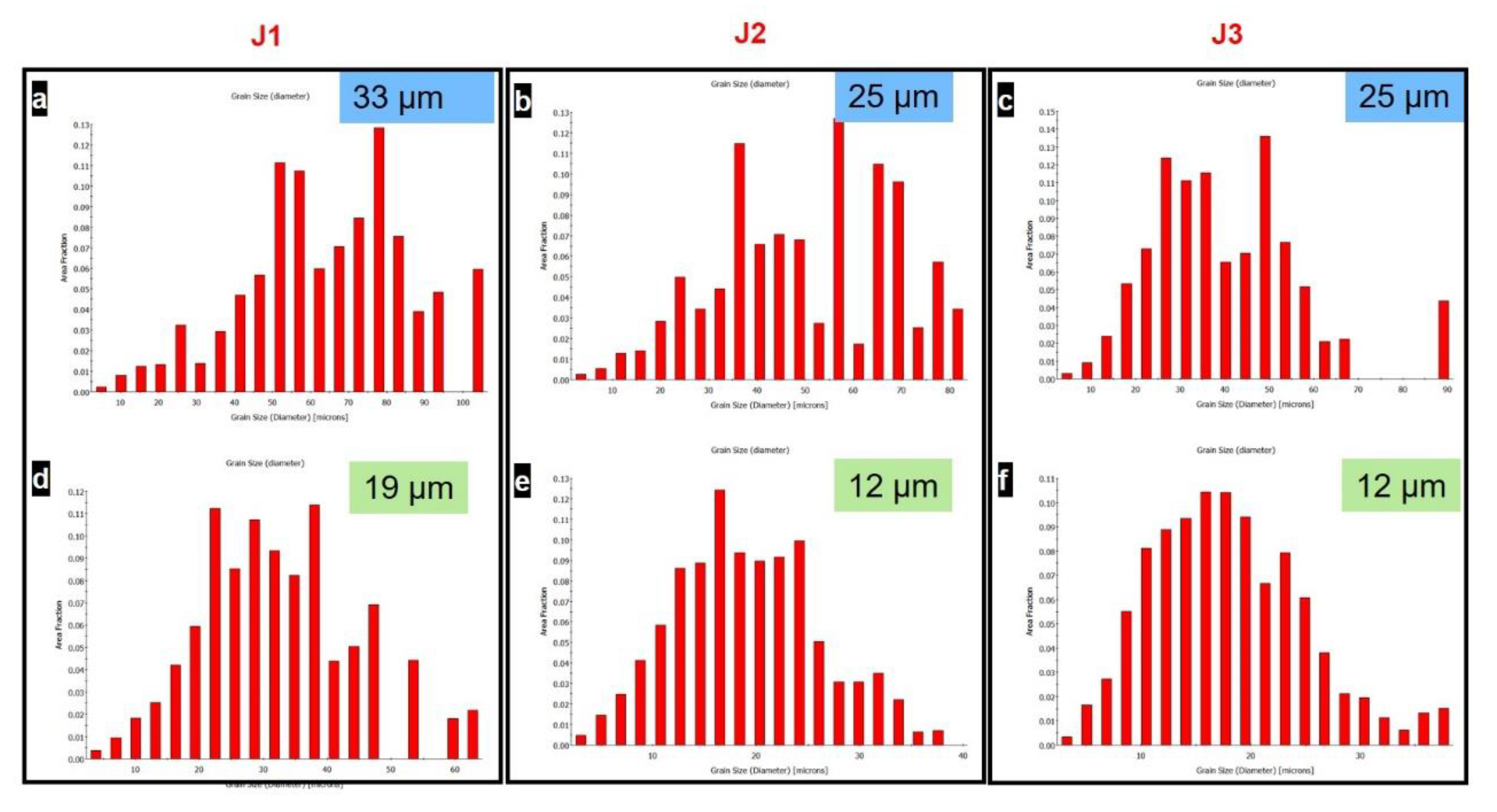
  • Microstructure observations using EBSD revealed a significant grain refinement effect for the rotation rate than that of the welding speed during dissimilar FSW of AA5754-AA5083 joints. The average grain size reduced from 19 µm to 12 µm by the reduction of the rotation rate from 600 rpm to 400 rpm at a constant welding speed of 60 mm/min, while almost similar average grain size (12 µm) was obtained by the reduction of welding speed from 60 mm/min to 20 mm/min at a constant rotation rate of 400 rpm.
  • The combination of the lowest applied tool rotation rate of 400 rpm and welding speed of 20 mm/min promoted a significant grain structure refinement, attributable to a decreased heat input compared with other welded joints at 400 rpm-40 mm/min and 600 rpm-60 mm/min.
  • The generally observed fine grain structure in the bottom region of nugget zones for all joints was explained by the thickness-induced high cooling capacity, preventing grain growth, besides being the bottom region affected by the pin not by the shoulder and pin together as the case in the top regions.
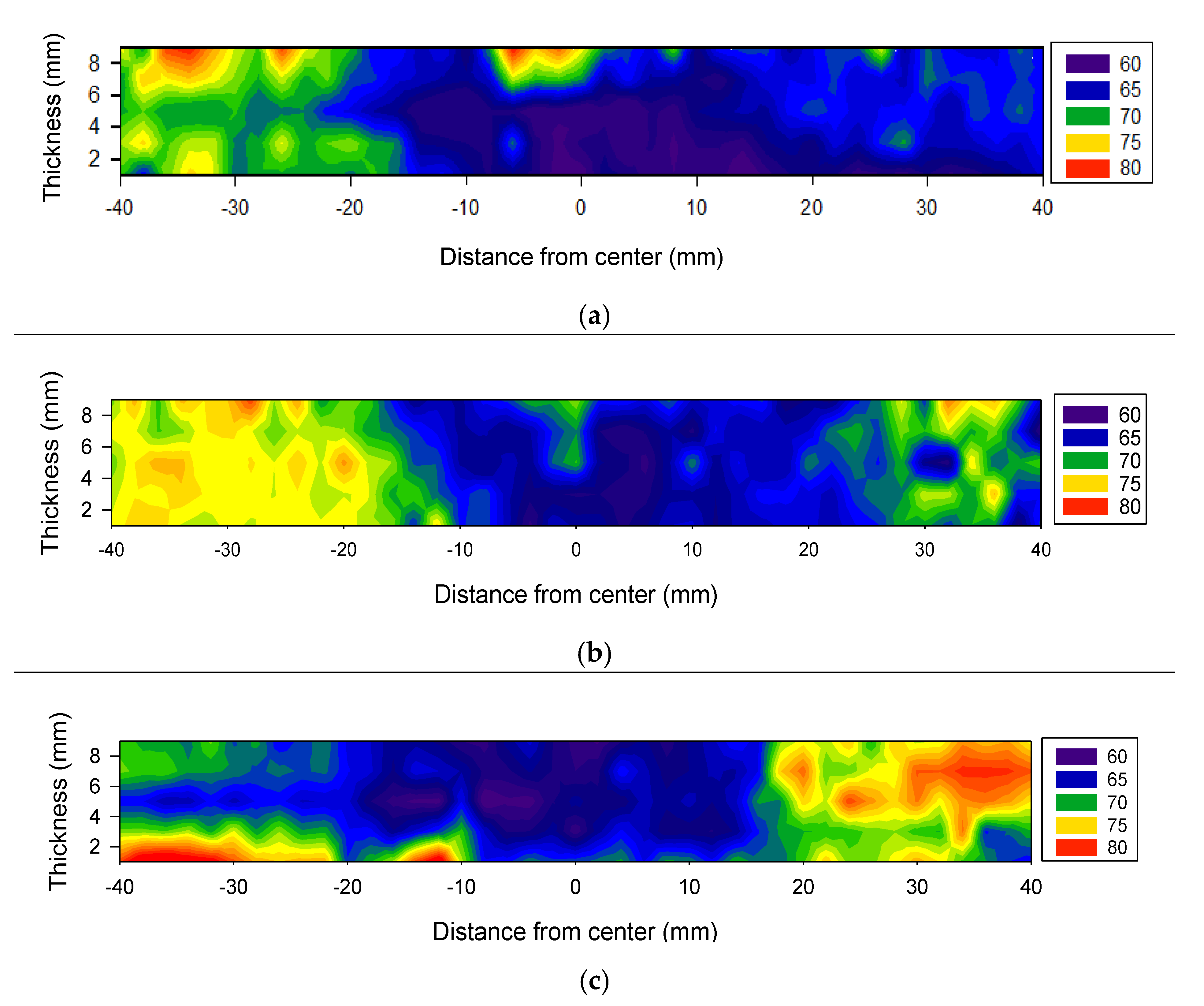
  • Hardness distribution maps revealed the softening of the nugget zone. The increased heat generated by the pin shoulder made the upper region of the nugget zone more soft than the lower zone.
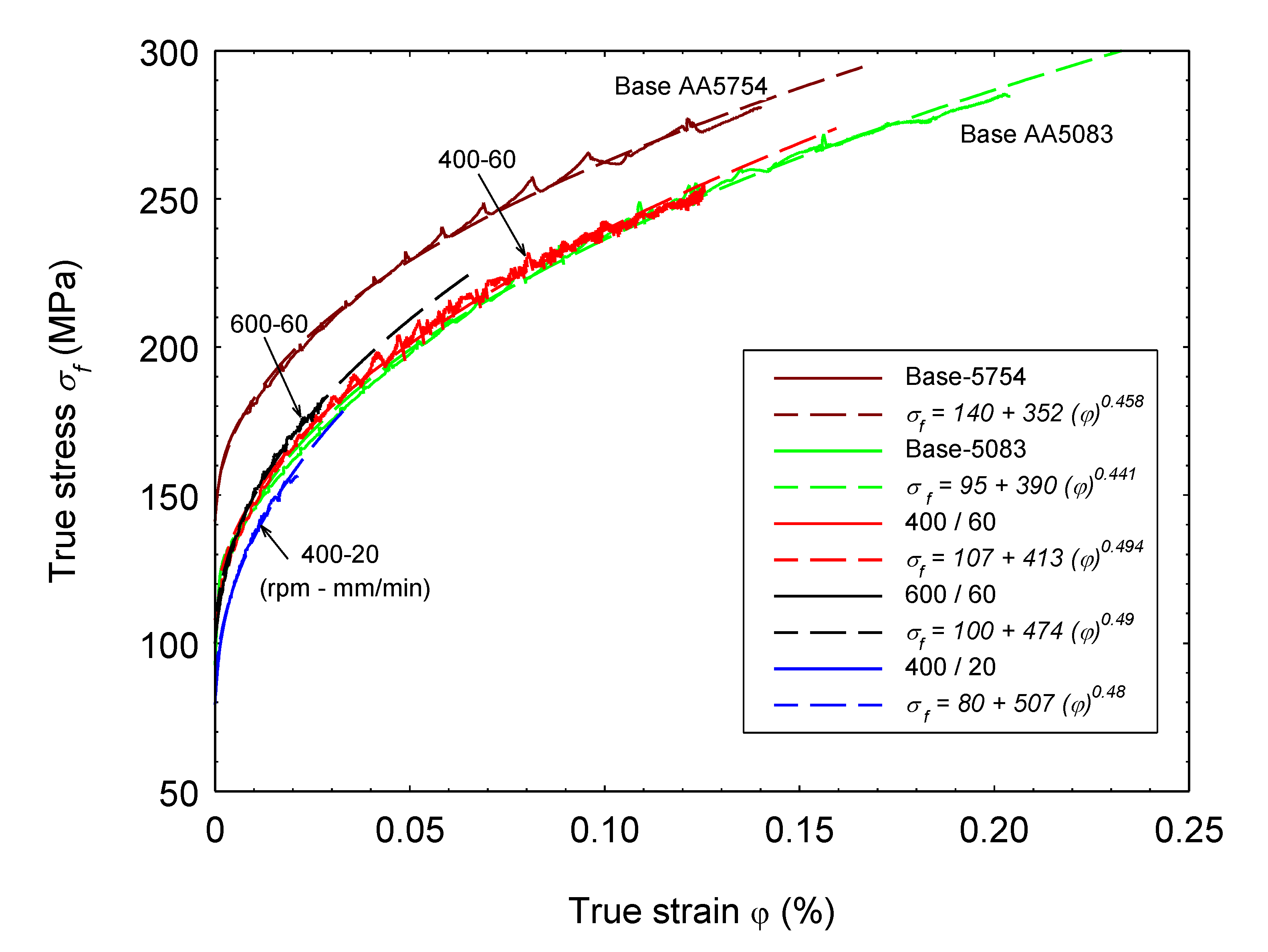
  • Tensile flow curves of the tested materials were well described using the Ludwik formula, and the materials parameters were sensitive to the hardening effect resulting from the FSW-ing process. The FSWed joint (400-60) showed the highest strengthening parameter (n = 0.494) with a moderate k value of 413 MPa.

Author Contributions

Conceptualization, S.A., E.A., and M.M.Z.A.; methodology, T.A., E.A., and M.M.E.-S.S.; validation, S.A., N.A.A., and E.A.; formal analysis, S.A. and M.M.Z.A.; investigation, M.M.E.-S.S., S.A., and E.A.; writing original draft preparation, T.A., S.A., and E.A.; writing—review and editing, T.A., M.M.Z.A., and N.A.A.; project administration, M.M.Z.A. and M.M.E.-S.S. All authors have read and agreed to the published version of the manuscript.

Funding

This research received no external funding.

Data Availability Statement

The data presented in this study are available on request from the corresponding author. The data are not publicly available due to the extremely large size.

Acknowledgments

The authors acknowledge the financial support rendered by the Science and Technology Development Fund (STDF), Ministry of Higher Education and Scientific Research, Egypt.

Conflicts of Interest

The authors declare no conflict of interest.

Abbreviations and Nomenclature

AAAluminum alloy
ASAdvancing side
BMBase material
DRVDynamic recovery
DRXDynamic recrystallization
EBSDElectron backscatter diffraction
EDAXEnergy dispersive analysis of X-rays
EDXEnergy-dispersive X-ray
FSWFriction stir welding
FSWedFriction stir welded
HABsHigh angle grain boundaries
HAZHeat affected zone
HIHeat input, J/mm
HVHardness Vickers
HRCHardnedd Rockwell C
IPFInverse pole figure
kMaterial parameter
LABsLow angle grain boundaries
MgMagnesium
MnManganese
nStrengthening parameter
NDNormal direction
NGNugget zone
rpmRevolution per minute
RSRetreating side
SEMScanning electron microscope
SZStirred zone
TDTransverse direction
TMAZThermomechanical affected zone
vWelding speed, mm/min
WDWelding direction
WNWelding nugget
εEngineering strain
σEngineering stress
σ0.2%:0.2 offset yield stress, MPa
σfFlow stress, MPa
σUTS:Ultimate tensile strength, MPa
φTrue strain
ωRotational speed, rpm

References

  1. Sahu, P.K.; Pal, S.; Pal, S.K.; Jain, R. Influence of Plate Position, Tool Offset and Tool Rotational Speed on Mechanical Properties and Microstructures of Dissimilar Al/Cu Friction Stir Welding Joints. J. Mater. Process. Technol. 2016, 235, 55–67. [Google Scholar] [CrossRef]
  2. Mabuwa, S.; Msomi, V. Review on Friction Stir Processed Tig and Friction Stirwelded Dissimilar Alloy Joints. Metals 2020, 10, 142. [Google Scholar] [CrossRef] [Green Version]
  3. Singh, V.P.; Patel, S.K.; Ranjan, A.; Kuriachen, B. Recent Research Progress in Solid State Friction-Stir Welding of Aluminium–Magnesium Alloys: A Critical Review. J. Mater. Res. Technol. 2020, 9, 6217–6256. [Google Scholar] [CrossRef]
  4. Mehta, K.P. A review on friction-based joining of dissimilar aluminum-steel joints. J. Mater. Res. 2019, 34, 78–96. [Google Scholar] [CrossRef] [Green Version]
  5. Ahmed, M.M.Z.; Seleman, M.M.E.; Zidan, Z.A.; Ramadan, R.M.; Ataya, S.; Alsaleh, N.A. Microstructure and Mechanical Properties of Dissimilar Friction Stir Welded AA2024-T4/AA7075-T6 T-Butt Joints. Metals 2021, 11, 128. [Google Scholar] [CrossRef]
  6. Cabibbo, M.; Forcellese, A.; Santecchia, E.; Paoletti, C.; Spigarelli, S.; Simoncini, M. New Approaches to Friction Stir Welding of Aluminum Light-Alloys. Metals 2020, 10, 233. [Google Scholar] [CrossRef] [Green Version]
  7. Oliveira, J.P.; Ponder, K.; Brizes, E.; Abke, T.; Edwards, P.; Ramirez, A.J. Combining Resistance Spot Welding and Friction Element Welding for Dissimilar Joining of Aluminum to High Strength Steels. J. Mater. Process. Technol. 2019, 273, 116192. [Google Scholar] [CrossRef]
  8. Ahmed, M.M.Z.; Ahmed, E.; Hamada, A.S.; Khodir, S.A.; Seleman, M.E.-S.; Wynne, B.P. Microstructure and Mechanical Properties Evolution of Friction Stir Spot Welded High-Mn Twinning-Induced Plasticity Steel. Mater. Des. 2016, 91. [Google Scholar] [CrossRef]
  9. Merklein, M.; Johannes, M.; Lechner, M.; Kuppert, A. A Review on Tailored Blanks—Production, Applications and Evaluation. J. Mater. Process. Technol. 2014, 214, 151–164. [Google Scholar] [CrossRef]
  10. El Rayes, M.M.; Soliman, M.S.; Abbas, A.T.; Pimenov, D.Y.; Erdakov, I.N.; Abdel-mawla, M.M. Effect of Feed Rate in FSW on the Mechanical and Microstructural Properties of AA5754 Joints. Adv. Mater. Sci. Eng. 2019, 2019, 4156176. [Google Scholar] [CrossRef] [Green Version]
  11. Ahmed, M.M.Z.; Ataya, S.; Seleman, M.M.E.; Mahdy, A.M.A.; Alsaleh, N.A.; Ahmed, E. Heat Input and Mechanical Properties Investigation of Friction Stir Welded AA5083/AA5754 and AA5083/AA7020. Metals 2021, 11, 68. [Google Scholar] [CrossRef]
  12. Ahmed, M.M.Z.; Ataya, S.; Seleman, M.E.-S.; Ammar, H.R.; Ahmed, E. Friction Stir Welding of Similar and Dissimilar AA7075 and AA5083. J. Mater. Process. Technol. 2017, 242, 77–91. [Google Scholar] [CrossRef]
  13. Sangalli, G.; Lemos, G.V.B.; Martinazzi, D.; De Lima Lessa, C.R.; Beskow, A.B.; Reguly, A. Towards Qualification of Friction Stir Welding to AA5083-O and AA5052-O Aluminum Alloys. Mater. Res. 2019. [Google Scholar] [CrossRef]
  14. Ahmed, M.M.Z.; Seleman, M.E.-S.; Shazly, M.; Attallah, M.M.; Ahmed, E. Microstructural Development and Mechanical Properties of Friction Stir Welded Ferritic Stainless Steel AISI 409. J. Mater. Eng. Perform. 2019, 28, 6391–6406. [Google Scholar] [CrossRef]
  15. Ahmed, M.M.Z.; Wynne, B.P.; Martin, J.P. Effect of Friction Stir Welding Speed on Mechanical Properties and Microstructure of Nickel Based Super Alloy Inconel 718. Sci. Technol. Weld. Join. 2013, 18, 680–687. [Google Scholar] [CrossRef]
  16. Hamada, A.S.; Järvenpää, A.; Ahmed, M.M.Z.; Jaskari, M.; Wynne, B.P.; Porter, D.A.; Karjalainen, L.P. The Microstructural Evolution of Friction Stir Welded AA6082-T6 Aluminum Alloy during Cyclic Deformation. Mater. Sci. Eng. A 2015, 642, 366–376. [Google Scholar] [CrossRef]
  17. Khodir, S.A.; Ahmed, M.M.Z.; Ahmed, E.; Mohamed, S.M.R.; Abdel-Aleem, H. Effect of Intermetallic Compound Phases on the Mechanical Properties of the Dissimilar Al/Cu Friction Stir Welded Joints. J. Mater. Eng. Perform. 2016, 25, 4637–4648. [Google Scholar] [CrossRef]
  18. Refat, M.; Elashery, A.; Toschi, S.; Ahmed, M.M.Z.; Morri, A.; El-Mahallawi, I.; Ceschini, L. Microstructure, Hardness and Impact Toughness of Heat-Treated Nanodispersed Surface and Friction Stir-Processed Aluminum Alloy AA7075. J. Mater. Eng. Perform. 2016, 25, 5087–5101. [Google Scholar] [CrossRef]
  19. Hoziefa, W.; Toschi, S.; Ahmed, M.M.Z.; Morri, A.; Mahdy, A.A.; Seleman, M.E.-S.; El-Mahallawi, I.; Ceschini, L.; Atlam, A. Influence of Friction Stir Processing on the Microstructure and Mechanical Properties of a Compocast AA2024-Al2O3 Nanocomposite. Mater. Des. 2016, 106, 273–284. [Google Scholar] [CrossRef]
  20. Zayed, E.M.; El-Tayeb, N.S.M.; Ahmed, M.M.Z.; Rashad, R.M. Development and Characterization of AA5083 Reinforced with SiC and Al2O3 Particles by Friction Stir Processing. In Engineering Design Applications; Springer: Cham, Switzerland, 2019; Volume 92. [Google Scholar]
  21. Oliveira, J.P.; Duarte, J.F.; Inácio, P.; Schell, N.; Miranda, R.M.; Santos, T.G. Production of Al / NiTi Composites by Friction Stir Welding Assisted by Electrical Current. JMADE 2017, 113, 311–318. [Google Scholar] [CrossRef] [Green Version]
  22. Tonelli, L.; Refat, M.; Toschi, S.; Ahmed, M.M.Z.; Ahmed, E.; Morri, A.; El-Mahallawi, I.; Ceschini, L. Production of AlSi12CuNiMg/Al2O3 Micro/Nanodispersed Surface Composites Using Friction Stir Processing for Automotive Applications BT—Friction Stir Welding and Processing X. In Friction Stir Welding and Processing X; Hovanski, Y., Mishra, R., Sato, Y., Upadhyay, P., Yan, D., Eds.; Springer International Publishing: Cham, Switzerland, 2019; pp. 233–242. [Google Scholar]
  23. Costa, A.M.S.; Oliveira, J.P.; Pereira, V.F.; Nunes, C.A.; Ramirez, A.J.; Tschiptschin, A.P. Ni-Based Mar-M247 Superalloy as a Friction Stir Processing Tool. J. Mater. Process. Technol. 2018, 262, 605–614. [Google Scholar] [CrossRef]
  24. Ahmed, M.M.Z.Z.; Wynne, B.P.; Rainforth, W.M.; Addison, A.; Martin, J.P.; Threadgill, P.L. Effect of Tool Geometry and Heat Input on the Hardness, Grain Structure, and Crystallographic Texture of Thick-Section Friction Stir-Welded Aluminium. Metall. Mater. Trans. A Phys. Metall. Mater. Sci. 2019, 50, 271–284. [Google Scholar] [CrossRef]
  25. Cabibbo, M.; Forcellese, A.; El Mehtedi, M.; Simoncini, M. Double Side Friction Stir Welding of AA6082 Sheets: Microstructure and Nanoindentation Characterization. Mater. Sci. Eng. A 2014, 590, 209–217. [Google Scholar] [CrossRef]
  26. Su, H.; Wu, C.S.; Bachmann, M.; Rethmeier, M. Numerical Modeling for the Effect of Pin Profiles on Thermal and Material Flow Characteristics in Friction Stir Welding. Mater. Des. 2015, 77, 114–125. [Google Scholar] [CrossRef]
  27. Sarkari Khorrami, M.; Kazeminezhad, M.; Kokabi, A.H. Microstructure Evolutions after Friction Stir Welding of Severely Deformed Aluminum Sheets. Mater. Des. 2012, 40, 364–372. [Google Scholar] [CrossRef]
  28. Kumbhar, N.T.; Sahoo, S.K.; Samajdar, I.; Dey, G.K.; Bhanumurthy, K. Microstructure and Microtextural Studies of Friction Stir Welded Aluminium Alloy 5052. Mater. Des. 2011, 32, 1657–1666. [Google Scholar] [CrossRef]
  29. Kim, N.K.; Kim, B.C.; An, Y.G.; Jung, B.H.; Song, S.W.; Kang, C.Y. The Effect of Material Arrangement on Mechanical Properties in Friction Stir Welded Dissimilar A5052/A5J32 Aluminum Alloys. Met. Mater. Int. 2009, 15, 671–675. [Google Scholar] [CrossRef]
  30. Mastanaiah, P.; Sharma, A.; Reddy, G.M. Dissimilar Friction Stir Welds in AA2219-AA5083 Aluminium Alloys: Effect of Process Parameters on Material Inter-Mixing, Defect Formation, and Mechanical Properties. Trans. Indian Inst. Met. 2016, 67, 1397–1415. [Google Scholar] [CrossRef]
  31. Kalemba-Rec, I.; Kopyściański, M.; Miara, D.; Krasnowski, K. Effect of Process Parameters on Mechanical Properties of Friction Stir Welded Dissimilar 7075-T651 and 5083-H111 Aluminum Alloys. Int. J. Adv. Manuf. Technol. 2018, 97, 2767–2779. [Google Scholar] [CrossRef] [Green Version]
  32. Essa, A.R.S.; Ahmed, M.M.Z.; Mohamed, A.Y.A.; El-Nikhaily, A.E. An Analytical Model of Heat Generation for Eccentric Cylindrical Pin in Friction Stir Welding. J. Mater. Res. Technol. 2016, 5, 234–240. [Google Scholar] [CrossRef] [Green Version]
  33. Kasman, Ş.; Yenier, Z. Analyzing Dissimilar Friction Stir Welding of AA5754/AA7075. Int. J. Adv. Manuf. Technol. 2014, 70, 145–156. [Google Scholar] [CrossRef]
  34. Threadgill, P.L. Terminology in Friction Stir Welding. Sci. Technol. Weld. Join. 2007, 12, 357–360. [Google Scholar] [CrossRef]
  35. Threadgill, P.L.; Leonard, A.J.; Shercliff, H.R.; Withers, P.J. Friction Stir Welding of Aluminium Alloys. Int. Mater. Rev. 2009, 54, 49–93. [Google Scholar] [CrossRef]
  36. Rollett, A.; Humphreys, F.; Rohrer, G.S.; Hatherly, M. Recrystallization and Related Annealing Phenomena, 2nd ed.; Elsevier: Amsterdam, The Netherlands, 2004; ISBN 9780080441641. [Google Scholar]
  37. McQueen, H.J.; Blum, W. Dynamic Recovery: Sufficient Mechanism in the Hot Deformation of Al (<99.99). Mater. Sci. Eng. A 2000, 290, 95–107. [Google Scholar] [CrossRef]
  38. Su, J.-Q.Q.; Nelson, T.W.; Sterling, C.J. Microstructure Evolution during FSW/FSP of High Strength Aluminum Alloys. Mater. Sci. Eng. A 2005, 405, 277–286. [Google Scholar] [CrossRef]
  39. Fonda, R.W.; Bingert, J.F.; Colligan, K.J. Development of Grain Structure during Friction Stir Welding. Scr. Mater. 2004, 51, 243–248. [Google Scholar] [CrossRef]
  40. Ahmed, M.M.Z.; Elnaml, A.; Shazly, M.; Seleman, M.M.E. The Effect of Top Surface Lubrication on the Friction Stir Welding of Polycarbonate Sheets. Intern. Polym. Process. 2021, 1–9. [Google Scholar] [CrossRef]
  41. Ahmed, M.M.Z.; Wynne, B.P.; Rainforth, W.M.; Threadgill, P.L. Microstructure, Crystallographic Texture and Mechanical Properties of Friction Stir Welded AA2017A. Mater. Charact. 2012, 64, 107–117. [Google Scholar] [CrossRef]
  42. Zhang, F.; Su, X.; Chen, Z.; Nie, Z. Effect of Welding Parameters on Microstructure and Mechanical Properties of Friction Stir Welded Joints of a Super High Strength Al-Zn-Mg-Cu Aluminum Alloy. Mater. Des. 2015, 67, 483–491. [Google Scholar] [CrossRef]
  43. Cao, X.; Jahazi, M. Effect of Welding Speed on the Quality of Friction Stir Welded Butt Joints of a Magnesium Alloy. Mater. Des. 2009, 30, 2033–2042. [Google Scholar] [CrossRef]
  44. Bagheri, B.; Abbasi, M.; Dadaei, M. Effect of Water Cooling and Vibration on the Performances of Friction-Stir-Welded AA5083 Aluminum Joints. Metallogr. Microstruct. Anal. 2020, 9, 33–46. [Google Scholar] [CrossRef]
  45. Ahmed, M.M.Z.; Wynne, B.P.; Rainforth, W.M.; Threadgill, P.L. Quantifying Crystallographic Texture in the Probe-Dominated Region of Thick-Section Friction-Stir-Welded Aluminium. Scr. Mater. 2008, 59, 507–510. [Google Scholar] [CrossRef]
  46. Ahmed, M.M.Z.; Wynne, B.P.; Rainforth, W.M.; Threadgill, P.L. Through-Thickness Crystallographic Texture of Stationary Shoulder Friction Stir Welded Aluminium. Scr. Mater. 2011, 64, 45–48. [Google Scholar] [CrossRef]
  47. Zhao, Y.H.; Lin, S.B.; Qu, F.X.; Wu, L. Influence of Pin Geometry on Material Flow in Friction Stir Welding Process. Mater. Sci. Technol. 2006, 22, 45–50. [Google Scholar] [CrossRef]
  48. Sajuri, Z.; Mohamad Selamat, N.F.; Baghdadi, A.H.; Rajabi, A.; Omar, M.Z.; Kokabi, A.H.; Syarif, J. Cold-Rolling Strain Hardening Effect on the Microstructure, Serration-Flow Behaviour and Dislocation Density of Friction Stir Welded AA5083. Metals 2020, 10, 70. [Google Scholar] [CrossRef] [Green Version]
  49. Bintu, A.; Vincze, G.; Picu, R.C.; Lopes, A.B. Effect of Symmetric and Asymmetric Rolling on the Mechanical Properties of AA5182. Mater. Des. 2016, 100, 151–156. [Google Scholar] [CrossRef]
  50. Gabrielli, F.; Forcellese, A.; El Mehtedi, M.; Simoncini, M. Mechanical Properties and Formability of Cold Rolled Friction Stir Welded Sheets in AA5754 for Automotive Applications. Procedia Eng. 2017, 183, 245–250. [Google Scholar] [CrossRef]
  51. Hollomon, J.H. Tensile Deformation. Trans. AIME 1945, 126, 268–290. [Google Scholar]
  52. Yamada, H.; Kami, T.; Mori, R.; Kudo, T.; Okada, M. Strain Rate Dependence of Material Strength in AA5xxx Series Aluminum Alloys and Evaluation of Their Constitutive Equation. Metals 2018, 8, 576. [Google Scholar] [CrossRef] [Green Version]
  53. Swift, H.W. Plastic Instability under Plane Stress. J. Mech. Phys. Solids 1952, 1, 1–18. [Google Scholar] [CrossRef]
  54. Meckings, H.; Koccks, U.F. Kinetics of Flow and Strain Hardening. Acta Metall. 1981, 29, 1865–1875. [Google Scholar] [CrossRef]
  55. Estrin, Y.; Mecking, H. A unified phenomenological description of work hardening and creep based on one-parameter models. Acta Met. 1984, 32, 57–70. [Google Scholar] [CrossRef]
  56. Ludwik, P. Fließvorgänge Bei Einfachen Beanspruchungen. In Elemente der Technologischen Mechanik; Springer: Berlin/Heidelberg, Germany, 1909. [Google Scholar] [CrossRef]
Figure 1. Schematic representation of the friction stir welding process.
Metals 11 00181 g001
Figure 2. Tensile test specimen dimensions.
Metals 11 00181 g002
Figure 3. Microstructural characteristics of the AA5754 and AA5083 Al-alloys in the as-received condition. EBSD orientation map, corresponding grain boundaries map, and grain size distribution histograms for (a) AA5754 and (b) AA5083 Al-alloys.
Metals 11 00181 g003
Figure 4. Macrostructure representing three different FSWed AA5754-AA5083 joints J1, J2, and J3 prepared by applying different combinations of rotation and travel speeds (rpm-mm/min) of 600-60, 400-60, and 400-20, respectively. EBSD measurements were performed at the centerline in the NG zone for each joint at the corresponding specified top locations (ac) and bottom locations (df) for J1, J2, and J3, respectively. The inverse pole figure coloring (IPF) maps and their corresponding grain boundary (GB) maps are represented for all the denoted locations.
Metals 11 00181 g004
Figure 5. Distribution of grain diameters for the different dissimilar friction stir welded (FSWed) joints prepared using different rotation and travel speeds. (ac) at the top locations and (df) at the bottom locations in the NG zones of J1, J2, and J3, respectively.
Metals 11 00181 g005
Figure 6. IPF coloring maps with their corresponding (111) pole figures for the same data presented in Figure 4 after applying the required rotations to align the FSW reference frame with the shear reference frame. (ac) are the IPF maps after rotation and their corresponding (111) pole figures for the EBSD data obtained at the top locations given in Figure 4. (df) are the IPF maps after rotation and their corresponding (111) pole figures for the EBSD data obtained at the bottom locations given in Figure 4.
Metals 11 00181 g006
Figure 7. Hardness distribution maps over the cross-section of the FSWed joints (a) J1: 600 rpm–60 mm/min, (b) J2: 400 rpm 60 mm/min, and (c) J3: 400 rpm and 20 mm/min.
Metals 11 00181 g007
Figure 8. Engineering tensile stress-strain curves of the base alloys AA5083 and AA5754 and the FSWed dissimilar joints at the conditions 400 rpm/20 mm/min, 400 rpm/60 mm/min, and at 600 rpm/60 mm/min.
Metals 11 00181 g008
Figure 9. Description of the true tensile stress-strain curves of the base alloys AA5083 and AA5754 and the FSWed dissimilar joints using Ludwik formula.
Metals 11 00181 g009
Table 1. Friction stir welding conditions and tensile properties.
StateWelding ConditionsTensile Properties
#Heat Index
ω2/v
σUTS
(MPa)
Total Strain (%)Welding Efficiency (%)
Base AA5754 --25128.50--
Base AA5083 --23334--
AA5083-AA5754J160001785.5077
J226662242396
J380001534.3066
Table 2. Tensile flow parameters of the flow curves.
Stateω
(rpm)
v
(mm/min)
σ o
(MPa)
k
(MPa)
n
(--)
Base 5754----1403520.458
Base 5083----953900.441
FSWed600601004740.490
400601074130.494
40020805070.48
Publisher’s Note: MDPI stays neutral with regard to jurisdictional claims in published maps and institutional affiliations.

