Article

Enhanced Strength and Ductility by Introducing Nanobainitic Ferrite in Bainitic Steel Used in Sports Equipment

1
College of Physical Education and Health, East China Normal University, Shanghai 200241, China
2
Institute of Technology, Inner Mongolia First Machinery Group Corporation, Baotou 014030, China
3
Institute of Advanced Steels and Materials, School of Materials Science and Engineering, Shanghai Jiao Tong University, Shanghai 200240, China
4
School of Material Science and Engineering, Shanghai Institute of Technology, Shanghai 200240, China
*
Authors to whom correspondence should be addressed.
Metals 2021, 11(12), 2007; https://doi.org/10.3390/met11122007
Submission received: 30 October 2021 / Revised: 29 November 2021 / Accepted: 7 December 2021 / Published: 13 December 2021

Abstract

:
The mechanical properties of carbide-free bainitic steels used in sports equipment were investigated. The nanobainitic ferrite was introduced in bainitic steel to enhance the stability of blocky retained austenite (RA). The blocky RA formed in bainitic austempering process was coarse and led to poor mechanical properties. By introducing the nanobainitic ferrite into blocky RA, the yield strength was improved remarkably, which was increased from 706 to 1180 MPa. Furthermore, the total elongation was almost twice the value compared to the traditional bainitic treatment. The improved mechanical properties were attributed to the enhanced stability of blocky RA. Furthermore, the increased carbon content in RA derived from the carbon dissolved in bainitic ferrite and the carbon trapped in dislocation or Cottrell atmosphere.

Graphical Abstract

1. Introduction

Steels are widely used in sports equipment, such as fitness equipment, and other competitive sports materials, such as bicycle and mountaineering equipment. Steels are by far the most reliable material, but they require continuous improvement in strength and ductility to extend service life or be lightweight. The carbide-free bainitic steel has received significant attention because it has superior mechanical properties such as high strength and good ductility due to its microstructure [1,2,3,4]. Bainitic transformation often has the incomplete transformation (ICT) phenomenon [5], which means that bainite transformation would be sluggish before reaching equilibrium. The untransformed austenite will be embedded into the aggregates of bainitic ferrite plates in the final microstructure. The carbon atoms will diffuse from bainitic ferrite into austenite when bainitic ferrite grows in the microstructure, and some of the carbon atoms precipitate as carbides in bainitic ferrite or RA. According to the diffusionless theory [5], once the carbon content in retained austenite reaches the T00′′ limit at which austenite and ferrite have the same Gibbs free energy, the bainite transformation stops.
In carbides-free bainitic steels, the volume fraction of blocky RA increases with increasing isothermal temperature. Thus, the bainite steels formed at high temperature often have a high working hardening rate but low ductility. Therefore, the amounts and stability of RA in bainite steels are critical for mechanical properties. Generally, blocky RA has low mechanical stability and transforms into blocky martensite during plastic deformation. The newly formed martensite will bear much stress which may act as the origin of cracks during tensile tests [6].
Bhadeshia [7] found that steel with a high carbon content (≥0.6 wt.%) could form a microstructure of nanosized bainitic ferrite and RA when austempering at a low temperature for a couple of days. The ultimate strength exceeds 2 GPa with a considerable toughness, which shows great potential for industrial application. It has been reported that the nanostructured bainitic ferrite continues to form when adopting multi-step heat treatments. It can divide the blocky RA into smaller ones and improve its mechanical stability [8,9]. However, the time of heat treatment lasts long.
In Q-P (Quenching-Partitioning) or Q-P-T (Quenching-Partitioning-Tempering) high strength steels [10,11], the carbon atoms will partition from martensite into RA and increase the carbon content in RA when tempering. This could significantly improve the stability of RA and the ductility of steel. However, for the bainite transformation, most carbon atoms have already diffused from bainitic ferrite into austenite during the bainitic ferrite transformation. Therefore, very little research focuses on the carbon partition and its effects on the stability of RA after bainite transformation. With the isothermal temperature decrease, the thickness of bainitic ferrite laths decrease, and dislocation density increases [12]. It was reported that the nanoscale bainitic ferrite always had a high density of dislocations and vacancies [7] and plenty of carbon atoms have been trapped in them [13,14,15,16,17]. The average carbon content in the bainite steels could be as high as 14.0 at.% in a dislocation or Cottrell atmosphere detected by 3D atom probe tomography (3DAP) [15,18]. Furthermore, Caballero et al. [16] reported that the nanoscale bainitic ferrite has a tetragonal crystal structure which allows high amounts of carbon in solid solution, and the carbon content could reach 1.1 at.%, which is greatly beyond the paraequilibrium phase boundaries. It has been proven that the carbon content in RA increases when tempering although the bainite transformation has stopped [17,19,20]. But they seldom discussed the effect of this small part of carbon atoms from bainitic ferrite into RA on the mechanical properties.
Few research studies discuss the carbon partitioning and its effects on the stability of RA after bainite transformation. Thus, by introducing the nanobainitic ferrite into the blocky RA, and its effect on mechanical properties was investigated. Furthermore, the role of nanobainitic ferrite and carbon diffusion from bainitic ferrite into RA during tempering were also discussed.

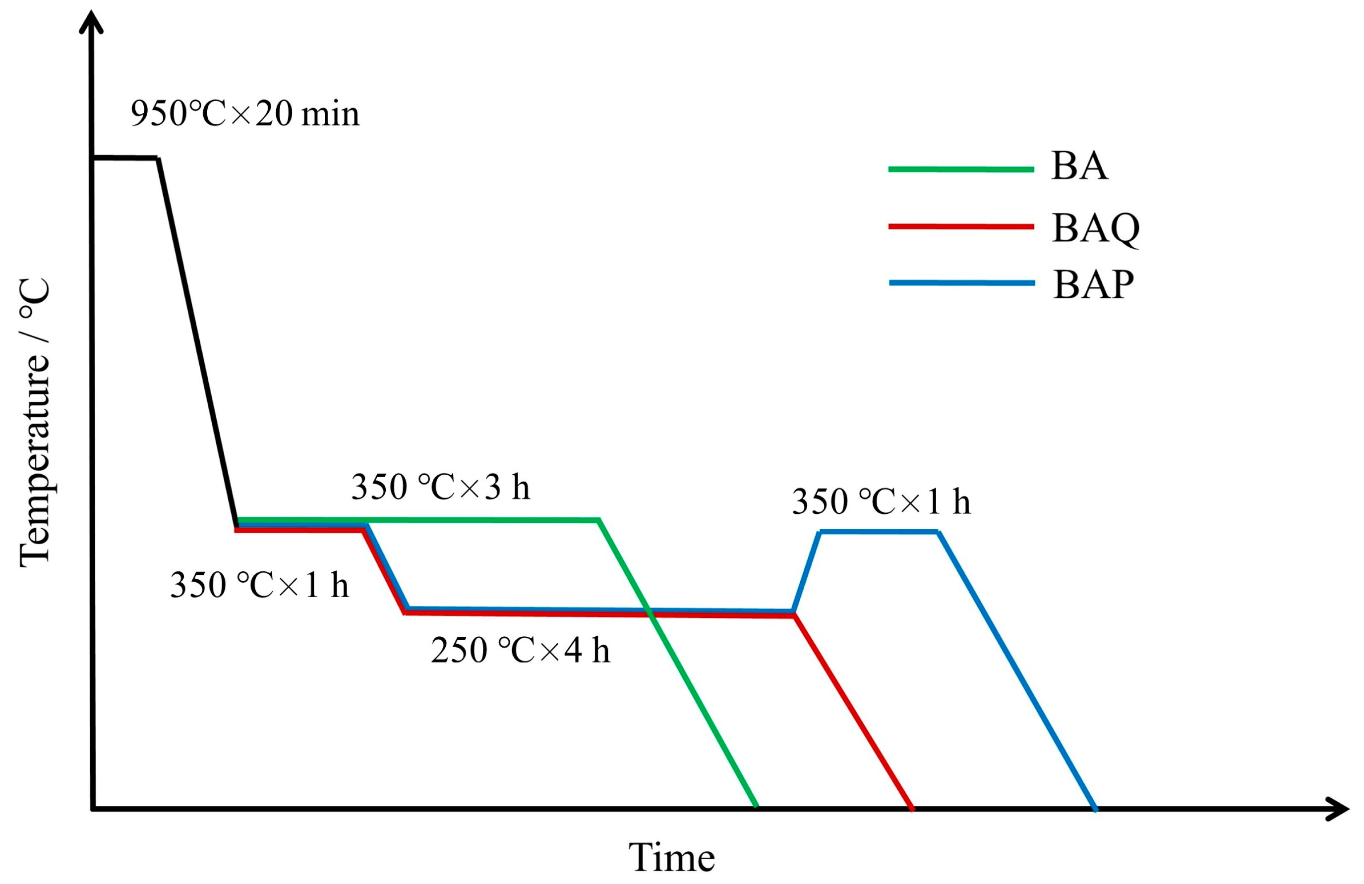
2. Materials and Methods

The chemical composition of the steel is Fe-1.0C-2.90Si-0.80Mn-0.51Cr-0.03Nb-0.25Mo (wt.%). The ingot was hot-rolled to a 40 mm × 40 mm × 1500 mm bar at 1150 °C, then slowly cooled in a sand mold.
The size of the specimen was 100 mm × 50 mm × 10 mm, and the BA (bainitic austempering), BAQ (bainitic austempering-quenching), and BAP (bainitic austempering-partitioning) heat treatments are shown in Figure 1. The BA samples were all austenitized at 950 °C (1223 K) for 20 min, then directly austempered at 350 °C (623 K) for 3 h before quenching into water. The BAP and BAQ samples were austempered at 350 °C (623 K) for 1 h in a salt bath, followed by isothermal heat treatment at 250 °C (523 K) for 4 h, then the BAQ sample was quenched into water directly, and the BAP continued to be tempered at 350 °C (623 K) for 1 h before quenching into water.
Tensile tests were conducted on the Zwick/Roell (BTC-T1-FR020 TN. A100, ZWickRoell, Ulm, Germany). The size of tensile sample was 16 mm × 5 mm × 1.5 mm with a gauge length of 16 mm, and the strain rate was 5.2 × 10⁻⁴ s−1. Three samples were prepared for each condition. The tensile samples were interrupted at different engineering strains, and their volume fraction of RA was measured by the saturation magnetization measurement in Physical Property Measurement System (PPMS-9T, Quantum Design, San Diego, CA, USA). Microstructures were characterized on a scanning electron microscope (GAIA3, TESCAN, Brno, Czech Republic) after mechanical polishing and etching in 4% nital solution. The dilatometry tests (DIL805A/D/T, Waters, Milford, MA, USA) were conducted on the samples with a diameter of 4 mm and a length of 10 mm, and the relative length changes were calculated. The radio of the fractions of film and blocky RA is given by Equation (1) [21]:
V f γ V b γ = 0.15 V BF V γ 0.15 V BF
where V and V are the volume fractions of film and blocky RA, respectively, and Vγ and VBF are the total volume fraction of RA and bainitic ferrite, respectively.
The T0 and T0′ lines were calculated by Thermos-Calc 2018 software, (Thermo-Calc, Stockholm, Sweden). The volume fraction and carbon content in RA were measured by an X-ray diffractometer (BRUKER, Bremen, Germany) at a speed of 1°/min. Besides, the carbon content in RA was calculated by the following Equation (2) [22]:
a γ = 3.5780 + 0.033 w C + 0.00095 w M n + 0.0006 w C r + 0.0031 w M o
where a γ is the lattice parameter of austenite in A , and w i is the content of element i in wt.%. For ferrite in Equation (3) [23]:
a α = 2.8664 + ( a F e 0.279 x C ) 2 ( a F e + 2.496 x C ) a F e 3 3 a F e 2 0.03 x S i + 0.06 x M n + 0.31 x M o + 0.05 x C r
where x i is the content in mole fraction and a F e = 2.8664 A is the lattice parameter of ferrite in pure iron.

3. Results

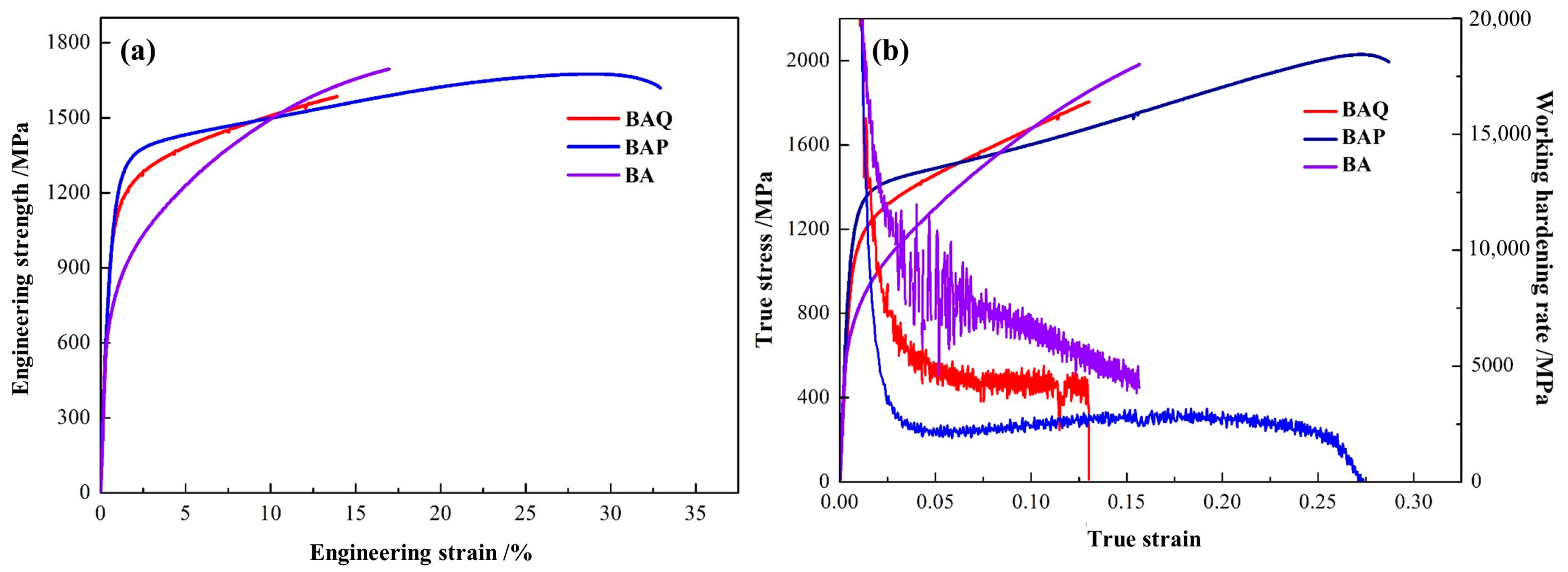
3.1. Mechanical Properties

The stress and strain curves of the BA, BAQ, and BAP, and corresponding work hardening rate curves are shown in Figure 2, and the data are listed in Table 1. The BA sample had the lowest yield strength, and both the ultimate strength and yield strength of the BAP sample are slightly higher than that in BAQ in Figure 2a. Furthermore, the elongation is significantly larger and almost twice the value in the BAP sample compared to the BA and BAQ in Table 1. However, the strain hardening capacity of the BAP showed a lower value than the BA and BAQ until fracture as shown in Figure 2b.

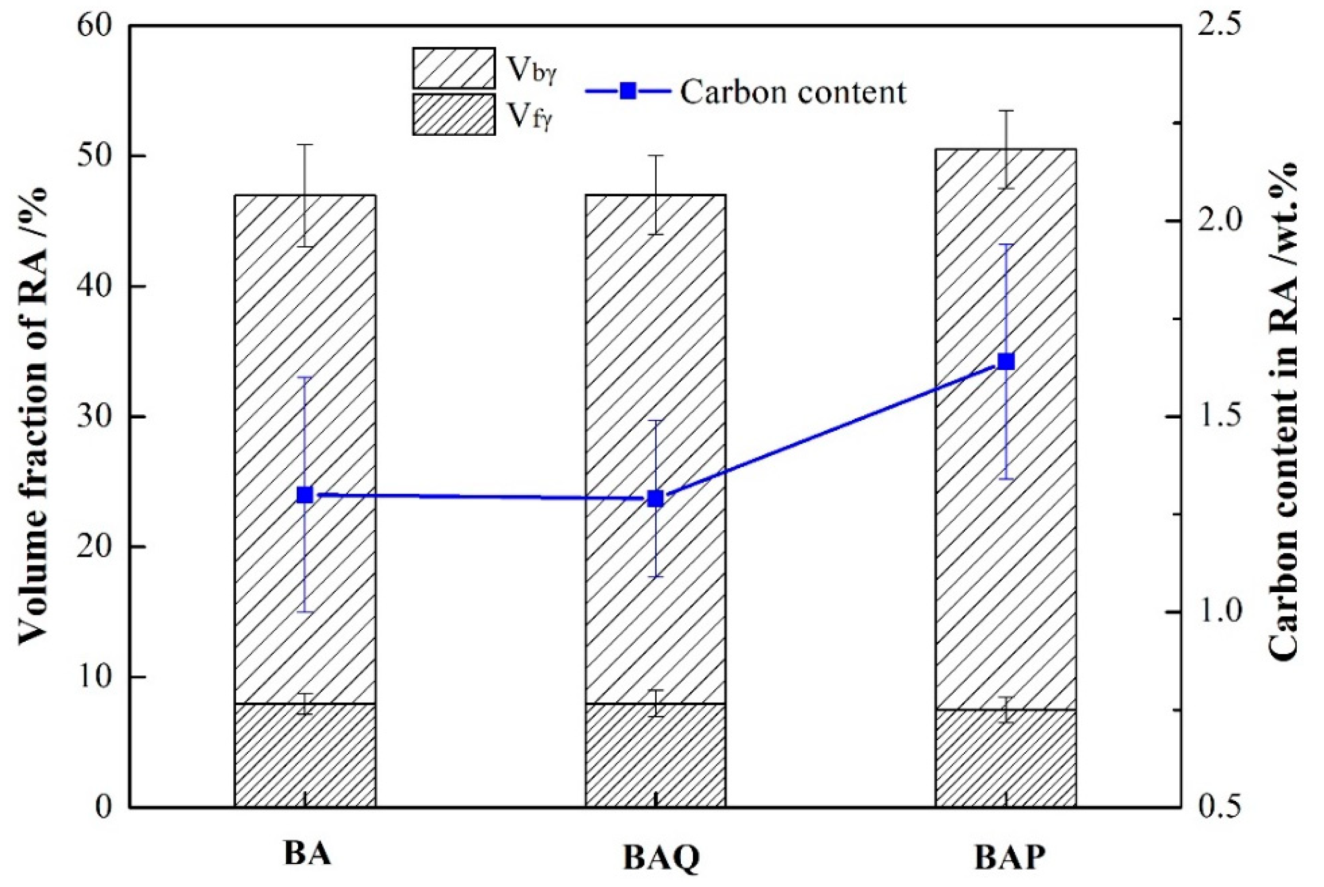
3.2. Volume Fraction and Carbon Concentration of RA
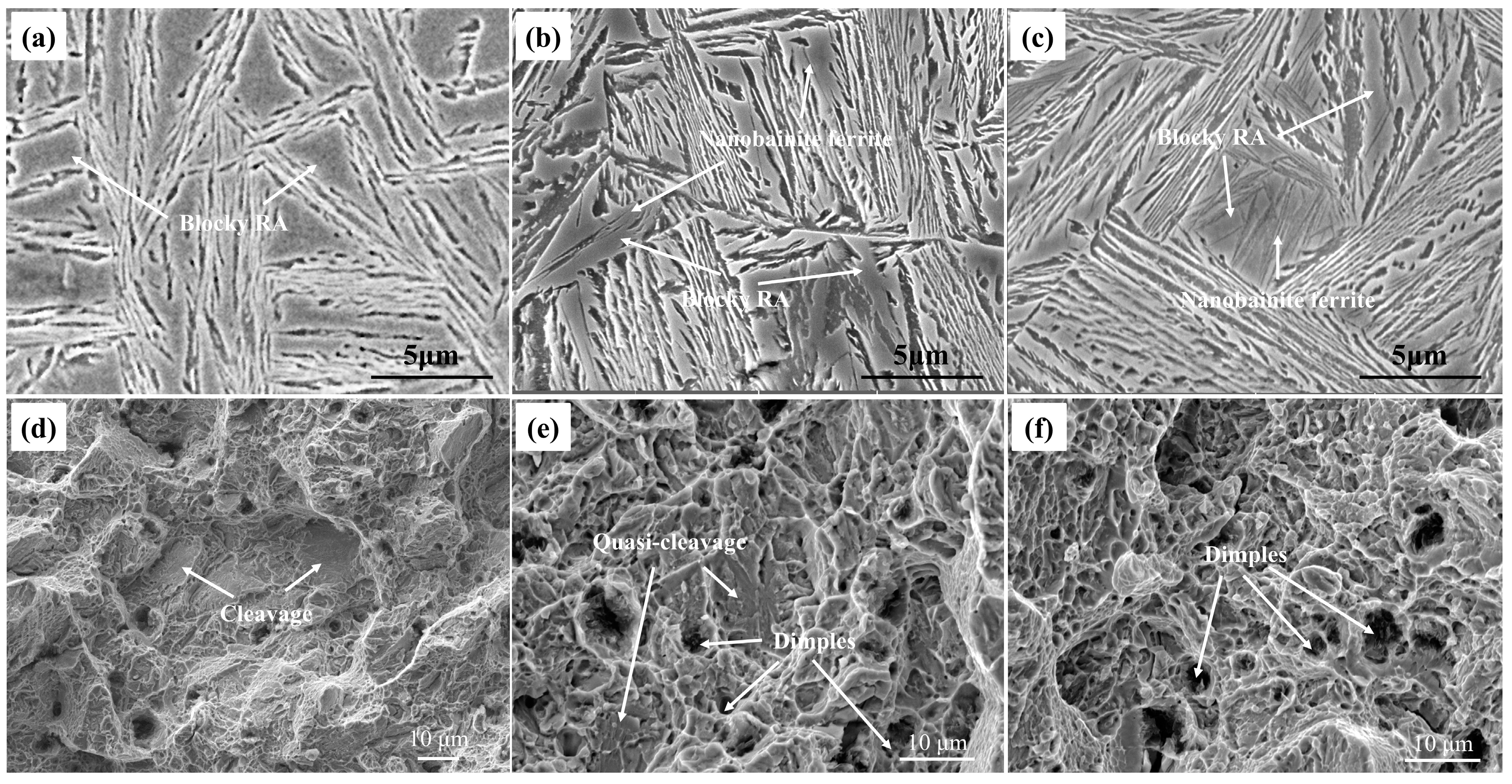
The volume fraction of RA in BA, BAQ, and BAP have almost the same, as shown in Figure 3. Furthermore, the ratio of film and blocky RA is also the same in these samples. However, the carbon content in bainitic ferrite and RA are different which is shown in Table 2. The BAP had the highest carbon content in RA, and the carbon in bainitic ferrite was the lowest among them. The dislocation density was also calculated from the XRD results using the modified Williamson-Hall equation [24,25,26]. It is shown that the dislocation density in bainitic ferrite decreases after tempering at 350 °C for 1 h.
The variation of volume fraction of RA at different strains has been shown in Figure 4. It demonstrates that the volume fraction of RA decreased with the true strain and transformed into martensite. To evaluate the mechanical stability of RA, the curves could be fitted by the exponent decay law by Equation (4) [27]:
f = f 0 exp ( k ε )
where f is the volume fraction of RA as function with ε, f0 is the initial volume fraction of RA, and k represents the mechanical stability of RA during tensile deformation. A big k value means low stability. In the present work, the RA stabilization in BA is the lowest among the three. The k was 6.86 in BAP and 9.56 in BAQ, respectively, which is shown in Figure 4. This indicates that the RA in BA or BAQ could be easily transformed into martensite which may become the origin of cracking during deformation.

3.3. Microstructure

It shows that the microstructure consisted of plates of bainitic ferrite and RA in Figure 5. Furthermore, there were two different types of RA, such as block-shaped and film-shaped. The thin needle-like bainitic ferrite could be seen in blocky RA in Figure 5b,c. The nanobainite ferrite formed during austempering at 250 °C divided the blocky RA into smaller ones. The main fracture morphology of the BA and BAQ are quasi-cleavage, cleavage and dimples, whereas almost dimples are present in the BAP fracture, as shown in Figure 5d–f).

3.4. Kinetics of Bainite Transformation

Figure 6 shows that the lengths changed in dilatometry tests for BA, and BAP samples. In Figure 6a, the length increased significantly before 1 h and then kept unchanged when the isothermal time exceeded 1 h at 350 °C, which means that the bainite transformation has been stasis in 1 h. Afterward, the length increased slightly once the isothermal temperature decreased to 250 °C for 4 h in Figure 6b. Furthermore, the length stayed flat during tempering at 350 °C for 1 h in Figure 6b.

4. Discussion

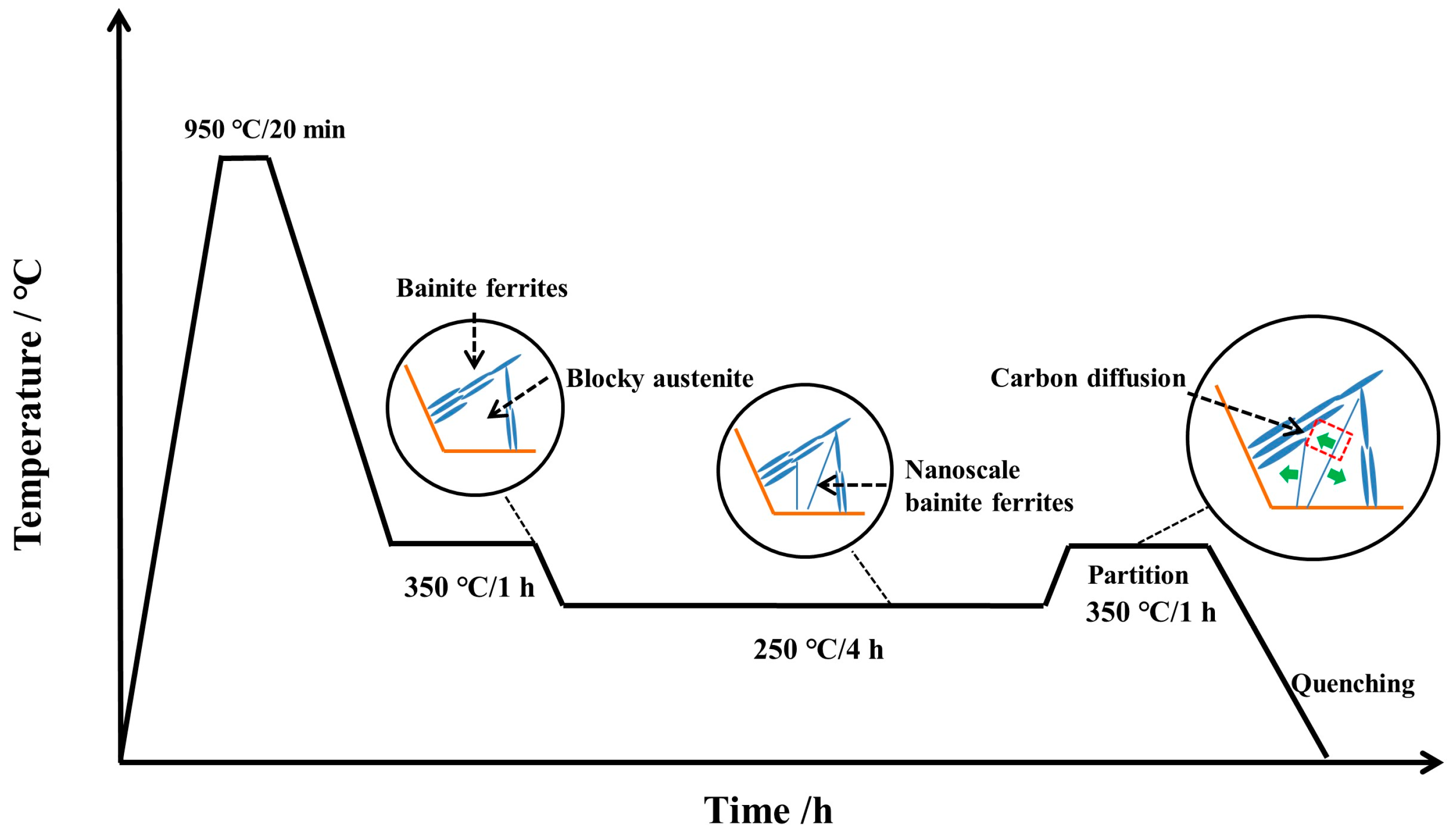
4.1. The Kinetics of Bainite Transformation

The relative length change during the partitioning and tempering could be attributed to carbon partitioning and phase transformations. It is reported that the bainite transformation would be stasis when the carbon content in RA exceeded the T0 line (T0′ was considered the stored energy in ferrite) [5]. The whole heat treatment process of BAP could be divided into three stages: (i) at 350 °C for 1 h. The transformation had been sluggish when time exceeds 1 h at 350 °C; (ii) at 250 °C for 4 h. The nanoscale bainite ferrite continued to form once decreasing the isothermal temperature to 250 °C in Figure 6b. This was because the driving force increased when the isothermal temperature decreased from 350 °C to 250 °C, and then triggered the bainite transformation again. Furthermore, the RA can accommodate more carbon atoms when decreasing isothermal temperature, which is shown in Figure 7. (iii) tempering at 350 °C for 1 h. The carbon concentration was 1.29 wt.% and 1.30 wt.% in BAQ and BA samples, respectively, which are marked in the black dot in Figure 7. The transformation would stop when the carbon content in RA reached the T0′ line based on diffusionless theory. And the length change stayed almost flat in Figure 6b, which indicates that no phase transformation occurred.

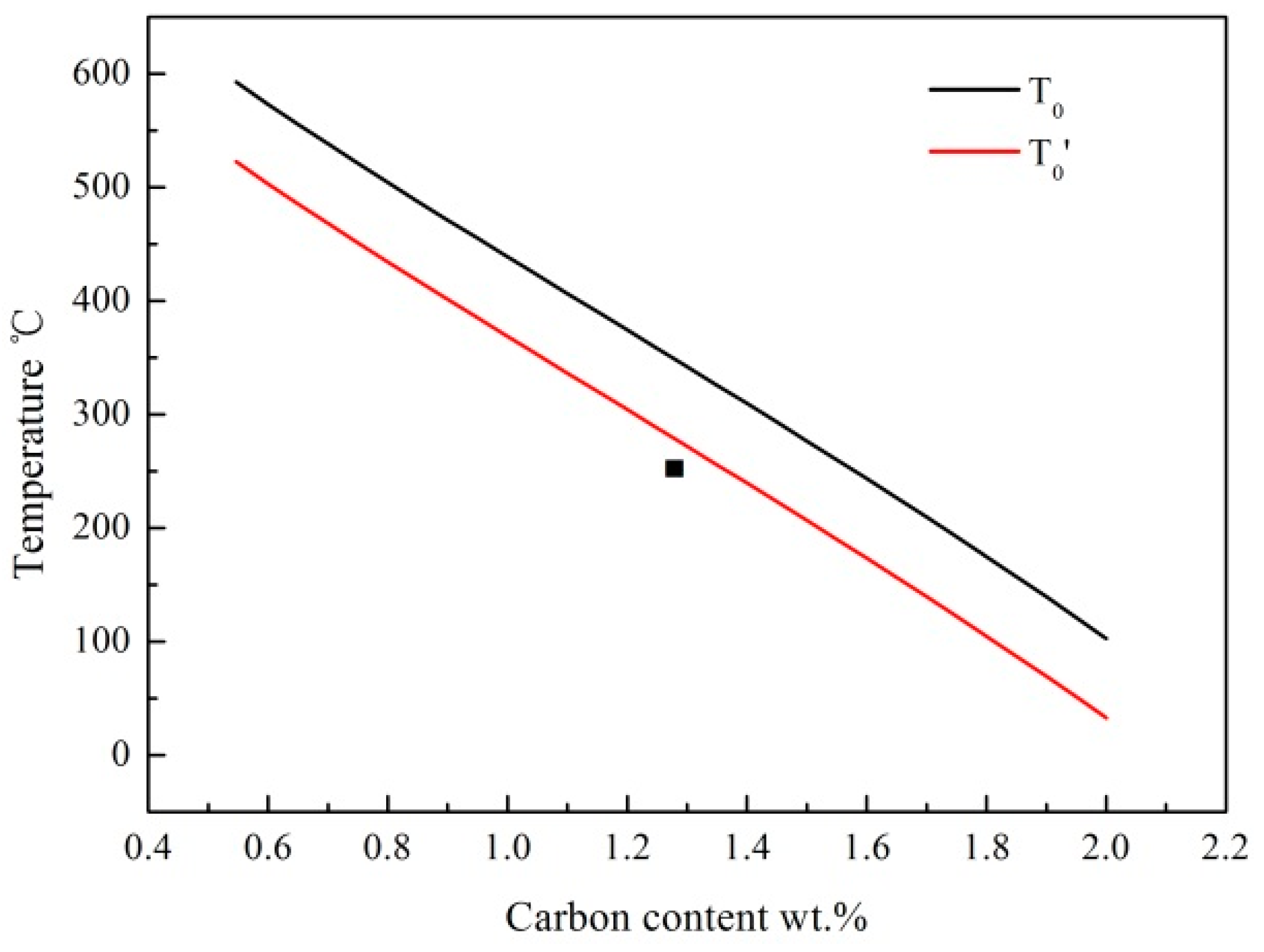
4.2. The Thermodynamics of Carbon Diffusion

The carbon concentration in RA increased from 1.29 wt.% in the BAQ sample to 1.66 wt.% in the BAP sample, which suggests that more carbon diffused from nanobainitic ferrite into retained austenite. It was reported that the nanostructured bainitic ferrite had a tetragonal crystal structure which allowed more amounts of carbon in solid solution than the paraequilibrium phase boundaries [14,16]. Thus, the dissolved carbon in ferrite was partitioned from ferrite to austenite when tempering at high temperature. This process could be calculated by building a thermodynamic model. During tempering at 350 °C, the alloying elements were considered to be nondiffusible, thus the phase boundary was thought to be immobilized, and only carbon atoms diffused from ferrite to RA. The calculation system was one-dimensional and was defined as a size of 50 nm, of which the size of austenite was 20 nm and the size of bainitic ferrite was 30 nm. The numerical simulation equation was the diffusion Equation (5):
c t = z ( c M μ z )
where c is the mole fraction of carbon, μ is the chemical potential of carbon, M is atomic mobility, t is the diffusion time. The initial condition is that Cγ = 1.29 wt.%, Cα = 0.024 wt.% which are listed in Table 2 and the results are shown in Figure 8.
It was shown that the carbon atoms partition from bainitic ferrite to RA according to the calculation results in Figure 8b,c. At t = 0.0001 s, a gradient concentration of carbon formed in the austenite because the diffusion rate in austenite was much lower than in ferrite [28]. In Figure 8c, when the partition time was 0.001 s, it reached the local equilibrium of carbon between ferrite and austenite. The calculated results show that carbon content increased from 1.29 wt.% to 1.32 wt.% in RA after partitioning, but the carbon content was approximately 1.66 wt.%. Therefore, apart from the carbon dissolved in ferrite, there were also other carbon contributions to the increase of carbon concentration in RA.
The carbon in defects, such as dislocations, are also considered to diffuse from bainitic ferrite to RA. It is [7] reported that the lower bainitic ferrite with high-density dislocations and Cottrell atmosphere, which could accommodate plenty of carbon atoms [13,14,15,16,17]. The carbon is presented not only in solid solution in bainitic ferrite but also in defects. It mainly considered two contributions at defects: the carbon atoms trapped in the dislocation strain field in ferrite lattice [29] and carbon atoms in Cottrell atmosphere [30]. However, it was difficult to quantify the carbon content trapped at defects by experimental methods. Therefore, it could be estimated by Equations (6)–(9) [29,30]:
C α ρ = N V C Ω × 100
N V C = Ω Γ ln { R / r 0 } Δ V C ρ b
C α C o t t r e l l = 8 ρ π r 0 2
C defects = C α   ρ + C α   Cottrell
where the C α ρ is the carbon in dislocation strain field, C α C o t t r e l l is the carbon content in Cottrell atmospheres, Cdefects is the carbon content in defects, N V C is the carbon atoms in a unit volume of ferrite without changing its lattice parameter, Ω = 4 b 3 / 3 3 / 2 is the atomic volume in bcc structure, Γ ln { R / r 0 } is the volume change per atomic volume Ω , Δ V c = 0.78   ×   10 29   m 3 is the volume change caused by the insertion of a single carbon atom into a unit cell of bcc iron, ρ is the dislocation density of bcc phase, b is the Burgers vector, r0 is a cylinder of radius about the dislocation line at the center. R = 140–400 nm is twice the true thickness of bainitic ferrite. Therefore, the results are listed in the Table 3.
In Table 3, C d e f e c t s in the BAP sample was much lower than BAQ which was resulted from the lower dislocation density. Tempering at 350 °C for 1 h, the dislocation density in BAQ had recovered and the carbon in dislocation or Cottrell atmosphere was released from defects and diffused into RA. Herein, the different C d e f e c t s could be contributing to the increase of carbon content in RA. Therefore, it could be concluded that the increase of carbon content in RA in BAP mainly consisted of two parts: the dissolved carbon in bainitic ferrite and the trapped carbon in dislocation or Cottrell atmosphere. These carbon atoms were considered to diffuse into the RA at the stage of tempering.
The calculation results are shown in Table 4. the carbon concentration rose from 1.29 ± 0.2 wt.% to 1.49 ± 0.2 wt.%. However, the carbon content of RA in the BAP was 1.66 ± 0.3 wt.%, thus the deviation still existed. This may be due to the possibility that carbon was segregated to ferrite/austenite interfaces, and they may also diffuse into RA when tempering, but it demonstrated that there was no such segregation [16]. Thus, the carbon in interfaces was neglected. Therefore, part of the carbon atom also existed in the form of carbides. However, the discrepancy of calculated carbon content was below the error and the carbon balance was almost satisfied.

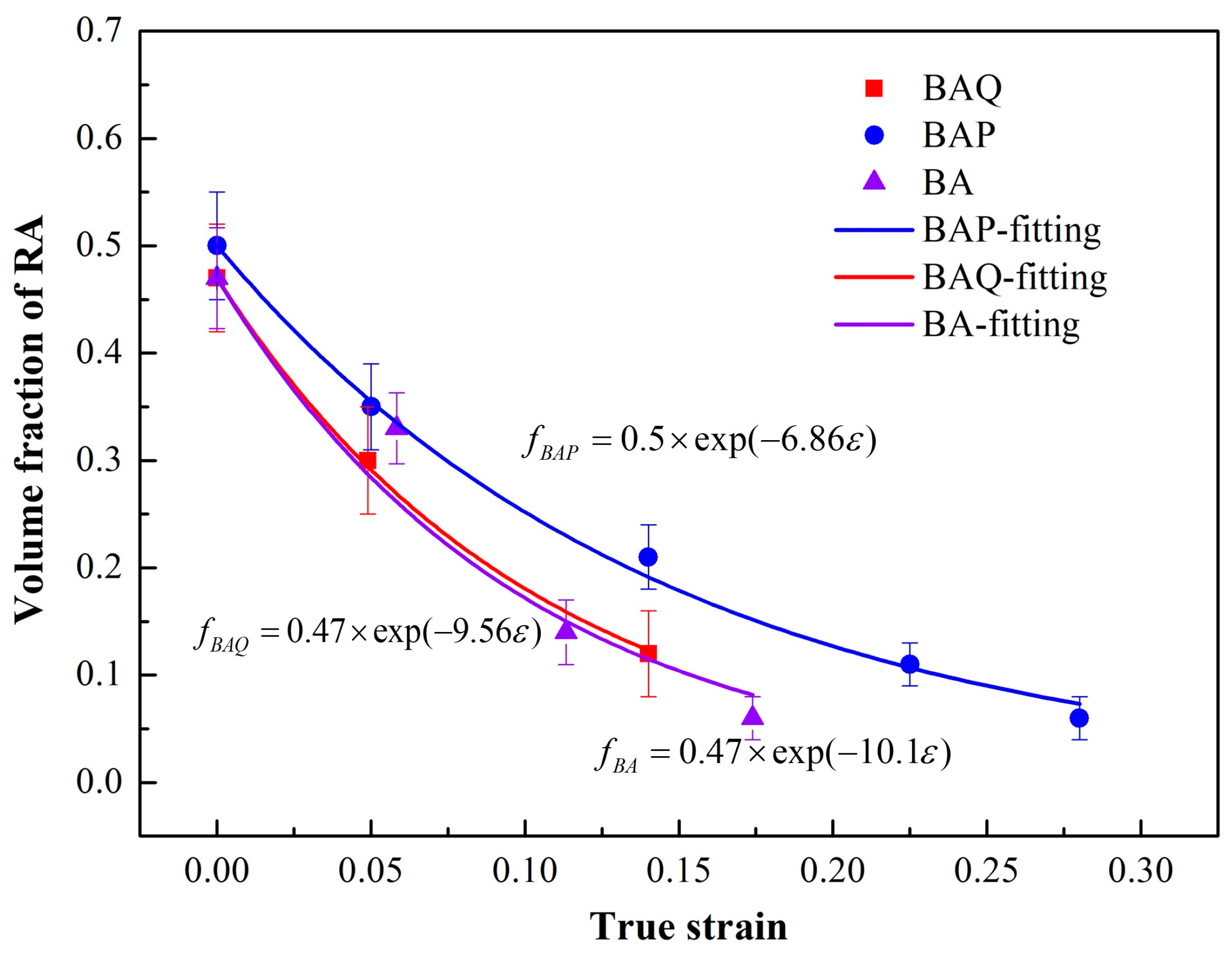
4.3. The Stability of Retained Austenite

The nanobainitic ferrite, as a second hard phase introduced in bainitic steel, not only divided the blocky RA into small parts but also released its carbon into the RA, which led to the enhancement of yield strength and elongation. As shown in Figure 9, the whole evolution of microstructures is summarized. The blocky and filmy RA generates at stage (i) and the bainite transformation has been stasis; then the nanoscale bainitic ferrite formed and divided the blocky RA into small ones at stage (ii); at stage (iii), no new phase formed and only carbon partitioning from bainitic ferrite to RA occurred.
There was a lot of blocky RA in the BA sample, and the main fracture mechanism was the cleavage fracture. The blocky RA was not favorable for ductility and toughness due to its poor stability. The strain hardening capacity of three samples: BA > BAQ > BAP, and the BAP showed low strain hardening rate at the low strain region but it increased with ongoing deformation. The blocky RA deformed easily in the early tensile deformation stage. When continuing to deform with deformation induced martensite, plenty of geometrically necessary dislocations will be generated at phase boundaries to accommodate the strain gradient [31]. This will lead the dislocation pile-ups around the boundaries and increase the back stress [32,33]. Although the RA accommodated the deformation at an early stage by transformation, the strong dislocation strengthening in ferrite due to transformation also generated high strain localization. Therefore, the unstable blocky RA transforms at an early stage contributes to high internal stress, and improves the strain hardening rate.
The bainite transformation austempering at 350 °C had been finished in 1 h. However, blocky RA could continue to transform into nanoscale bainitic ferrite when decreasing the isothermal temperature. The nanobainitic ferrite nucleated at the phase boundaries and grows, then cuts the blocky RA into small pieces. Thus, the grain size had been refined which enhanced the strength without compromising plasticity [34,35]. Furthermore, the nanobainitic ferrite itself had high strength due to its nanosized laths. Therefore, by inducing the nanobainitic ferrite into blocky RA, the yield strength had greatly increased from 706 MPa in the BA sample to 1070 MPa in the BAQ sample.
After tempering at 350 °C for 1 h, the elongation was significantly improved from 14% to 33% in BAP because the stability of RA increased due to high carbon content. During the tensile deformation, great elongation probably originated from the collaborative deformation. Furthermore, the stable RA altered the stress distribution between RA and bainitic ferrite and carried more stress which eliminated the stress concentration to prevent the local failure [36,37].

5. Conclusions

The mechanical properties and the stability of retained austenite in bainitic steels were discussed. The formation of nanobainite ferrite had mainly two contributions: divided the blocky RA into the small parts and the dissolved carbon in bainitic ferrite diffusing into blocky RA during tempering. The major new findings of this study were as follows:
(1) By introducing the nanobainite ferrite in bainite steel, the yield strength had greatly increased from 706 MPa in BA to 1180 MPa. Furthermore, a total elongation in BAP was almost twice that of BA sample.
(2) The RA in the BAP sample had higher stability than that in the BA sample, with a lower k value.
(3) The nanobainite ferrite divided blocky RA into ones with small sizes. Furthermore, the carbon atoms which were dissolved in bainitic ferrite or dislocation and Cottrell atmosphere will diffuse into RA during tempering.

Author Contributions

Conceptualization, X.J., Y.L. and Z.Y.; methodology, H.M. and Z.H.; software, X.J.; validation, H.M., Z.H. and X.J.; formal analysis, H.M. and Z.H.; investigation, H.M.; resources, Y.L.; data curation, Z.H.; writing—original draft preparation, H.M.; writing—review and editing, Y.L. and Z.Y.; visualization, H.M., Z.H. and X.J.; supervision, Y.L. and Z.Y.; project administration, X.J.; funding acquisition, Y.L. and X.J. All authors have read and agreed to the published version of the manuscript.

Funding

The authors are grateful for the financial support of the National Nature Science Foundation of China (No. 52001213). Also, this work is sponsored by the Shanghai Sailing Program (20YF1447200) and the “Chen Guang” project (20CG65) supported by the Shanghai Municipal Education Commission and Shanghai Education Development Foundation, Natural Science Foundation of Shanghai (20ZR1455300).

Institutional Review Board Statement

Not applicable.

Informed Consent Statement

Not applicable.

Data Availability Statement

Not applicable.

Acknowledgments

The authors are grateful for the financial support and all authors have read and agreed to the published version of the manuscript.

Conflicts of Interest

The authors declare no conflict of interest.

References

  1. Morales-Rivas, L.; Garcia-Mateo, C.; Sourmail, T.; Kuntz, M.; Rementeria, R.; Caballero, F.G. Ductility of Nanostructured Bainite. Metals 2016, 6, 302. [Google Scholar] [CrossRef]
  2. Gao, G.; Zhang, H.; Gui, X.; Tan, Z.; Bai, B.; Weng, Y. Enhanced strain hardening capacity in a lean alloy steel treated by a “disturbed” bainitic austempering process. Acta Mater. 2015, 101, 31–39. [Google Scholar] [CrossRef]
  3. Sugimoto, K.I.; Iida, T.; Sakaguchi, J.; Kashima, T. RA charactericstics and tensile properties in a TRIP bainitic sheet steels. ISIJ Int. 2000, 40, 902–908. [Google Scholar] [CrossRef]
  4. Caballero, F.G.; Roelofs, H.; Hasler, S.; Capdevila, C.; Chao, J.; Cornide, J.; Garcia-Mateo, C. Influence of bainite morphology on impact toughness of continuously cooled cementite free bainitic steels. Mater. Sci. Technol. 2012, 28, 95–102. [Google Scholar] [CrossRef] [Green Version]
  5. Bhadeshia, H.K.D.H.; Christian, J.W. Bainite in Steels. Metall. Mater. Trans. A 1990, 21, 767–797. [Google Scholar] [CrossRef]
  6. Wang, M.-M.; Hell, J.C.; Tasan, C. Martensite size effects on damage in quenching and partitioning steels. Scr. Mater. 2017, 138, 1–5. [Google Scholar] [CrossRef]
  7. Bhadeshia, H.K.D.H. Nanostructured bainite, Proceedings of the Royal Society A: Mathematical. Phys. Eng. Sci. 2009, 466, 3–18. [Google Scholar]
  8. Hase, K.; Garcia-Mateo, C.; Bhadeshia, H. Bimodal size-distribution of bainite plates. Mater. Sci. Eng. A 2006, 438-440, 145–148. [Google Scholar] [CrossRef] [Green Version]
  9. Hu, F.; Wu, K.M.; Wan, X.L.; Rodionova, I.; Shirzadi, A.A.; Zhang, F.C. Novel method for refinement of retained austenite in micro/nano-structured bainitic steels. Mater. Sci. Technol. 2017, 33, 1360–1365. [Google Scholar] [CrossRef] [Green Version]
  10. Hsu, T.; Zuyao, X.; Jin, X.; Rong, Y. Strengthening and Toughening Mechanisms of Quenching-Partitioning-Tempering (QPT) Steels. J. Alloys Compd. 2012, 577, S568–S571. [Google Scholar]
  11. Hsu, T.Y. Quenching–partitioning–tempering process for ultra-high strength steel. Int. Heat Treat. Surf. Eng. 2008, 2, 64–67. [Google Scholar]
  12. He, S.; He, B.; Zhu, K.; Huang, M. On the correlation among dislocation density, lath thickness and yield stress of bainite. Acta Mater. 2017, 135, 382–389. [Google Scholar] [CrossRef]
  13. Sampath, S.; Rementeria, R.; Huang, X.; Poplawsky, J.; Garcia-Mateo, C.; Caballero, F.; Janisch, R. The role of silicon, vacancies, and strain in carbon distribution in low temperature bainite. J. Alloys Compd. 2016, 673, 289–294. [Google Scholar] [CrossRef] [Green Version]
  14. Caballero, F.; Miller, M.; Garcia-Mateo, C. Carbon supersaturation of ferrite in a nanocrystalline bainitic steel. Acta Mater. 2010, 58, 2338–2343. [Google Scholar] [CrossRef] [Green Version]
  15. Caballero, F.; Yen, H.-W.; Miller, M.; Yang, J.-R.; Cornide, J.; Garcia-Mateo, C. Complementary use of transmission electron microscopy and atom probe tomography for the examination of plastic accommodation in nanocrystalline bainitic steels. Acta Mater. 2011, 59, 6117–6123. [Google Scholar] [CrossRef] [Green Version]
  16. Garcia-Mateo, C.; Jiménez, J.A.; Yen, H.-W.; Miller, M.; Morales-Rivas, L.; Kuntz, M.; Ringer, S.; Yang, J.-R.; Caballero, F. Low temperature bainitic ferrite: Evidence of carbon super-saturation and tetragonality. Acta Mater. 2015, 91, 162–173. [Google Scholar] [CrossRef] [Green Version]
  17. Caballero, F.; Miller, M.; Garcia-Mateo, C.; Cornide, J.; Santofimia, M. Temperature dependence of carbon supersaturation of ferrite in bainitic steels. Scr. Mater. 2012, 67, 846–849. [Google Scholar] [CrossRef] [Green Version]
  18. Caballero, F.; Miller, M.; Garcia-Mateo, C. Influence of transformation temperature on carbide precipitation sequence during lower bainite formation. Mater. Chem. Phys. 2014, 146, 50–57. [Google Scholar] [CrossRef] [Green Version]
  19. Peet, M.J.; Babu, S.; Miller, M.K.; Bhadeshia, H.K. Tempering of Low-Temperature Bainite. Metall. Mater. Trans. A 2017, 48A, 3410–3418. [Google Scholar] [CrossRef] [Green Version]
  20. Caballero, F.; Miller, M.; Clarke, A.; Garcia-Mateo, C. Examination of carbon partitioning into austenite during tempering of bainite. Scr. Mater. 2010, 63, 442–445. [Google Scholar] [CrossRef] [Green Version]
  21. Bhadeshia, H.K.D.H.; Edmonds, D.V. Bainite in silicon steels: New composition–property approach Part 1. Met. Sci. 1983, 17, 411–419. [Google Scholar] [CrossRef]
  22. Garcia-Mateo, C.; Peet, M.; Caballero, F.; Bhadeshia, H. Tempering of hard mixture of bainitic ferrite and austenite. Mater. Sci. Technol. 2004, 20, 814–818. [Google Scholar] [CrossRef] [Green Version]
  23. Bhadeshia, H.K.D.H.; David, S.A.; Vitek, J.M.; Reed, R.W. Stress induced transformation to bainite in Fe–Cr–Mo–C pressure vessel steel. Met. Sci. J. 1991, 7, 686–698. [Google Scholar] [CrossRef]
  24. Ungár, T.; Dragomir, I.; Révész, Á.; Borbély, A. The contrast factors of dislocations in cubic crystals: The dislocation model of strain anisotropy in practice. J. Appl. Crystallogr. 1999, 32, 992–1002. [Google Scholar] [CrossRef] [Green Version]
  25. Ungár, T.; Victoria, M.; Marmy, P.; Hanák, P.; Szenes, G. A new procedure of X-ray line profile analysis applied to study the dislocation structure and subgrain size-distributions in fatigued MANET steel. J. Nucl. Mater. 2000, 276, 278–282. [Google Scholar] [CrossRef]
  26. Renzetti, R.; Sandim, H.; Bolmaro, R.; Suzuki, P.A.; Möslang, A. X-ray evaluation of dislocation density in ODS-Eurofer steel. Mater. Sci. Eng. A 2012, 534, 142–146. [Google Scholar] [CrossRef]
  27. Sugimoto, K.-I.; Kobayashi, M.; Hashimoto, S.-I. Ductility and strain-induced transformation in a high-strength transformation-induced plasticity-aided dual-phase steel. Met. Mater. Trans. A 1992, 23, 3085–3091. [Google Scholar] [CrossRef]
  28. Nishikawa, A.S.; Santofimia, M.J.; Sietsma, J.; Goldenstein, H. Influence of bainite reaction on the kinetics of carbon redistribution during the Quenching and Partitioning process. Acta Mater. 2018, 142, 142–151. [Google Scholar] [CrossRef] [Green Version]
  29. Bhadeshia, H.K.D.H. Anomalies in carbon concentration determinations from nanostructured bainite. Mater. Sci. Technol. 2014, 31, 758–763. [Google Scholar] [CrossRef]
  30. Rementeria, R.; Jiménez, J.A.; Allain, S.Y.P.; Geandier, G.; Poplawsky, J.; Guo, W.; Urones-Garrote, E.; Garcia-Mateo, C.; Caballero, F.G. Quantitative assessment of carbon allocation anomalies in low temperature bainite. Acta Mater. 2017, 133, 333–345. [Google Scholar] [CrossRef]
  31. Wu, X.; Jiang, P.; Chen, L.; Yuan, F.; Zhu, Y.T. Extraordinary strain hardening by gradient structure. Proc. Natl. Acad. Sci. USA 2014, 111, 7197–7201. [Google Scholar] [CrossRef] [Green Version]
  32. Li, Y.; Li, W.; Hu, J.C.; Song, H.M.; Jin, X. Compatible strain evolution in two phases due to epsilon martensite transformation in duplex TRIP-assisted stainless steels with high hydrogen embrittlement resistance. Int. J. Plast. 2017, 88, 53–69. [Google Scholar] [CrossRef]
  33. Li, Y.; Li, W.; Liu, W.; Wang, X.; Hua, X.; Liu, H.; Jin, X. The austenite reversion and co-precipitation behavior of an ultra-low carbon medium manganese quenching-partitioning-tempering steel. Acta Mater. 2018, 146, 126–141. [Google Scholar] [CrossRef]
  34. Liu, G.; Zhang, G.J.; Jiang, F.; Ding, X.; Sun, Y.J.; Sun, J.; Ma, E. Nanostructured high-strength molybdenum alloys with unprecedented tensile ductility. Nat. Mater. 2013, 12, 344–350. [Google Scholar] [CrossRef] [PubMed]
  35. Chokshi, A.; Rosen, A.; Karch, J.; Gleiter, H. On the validity of the hall-petch relationship in nanocrystalline materials. Scr. Met. 1989, 23, 1679–1683. [Google Scholar] [CrossRef] [Green Version]
  36. Zhao, H.; Li, W.; Wang, L.; Zhou, S.; Jin, X. The Deformation Behavior Analysis and Mechanical Modeling of Step/Intercritical Quenching and Partitioning-Treated Multiphase Steels. Met. Mater. Trans. A 2016, 47, 3943–3955. [Google Scholar] [CrossRef]
  37. Zhao, H.; Li, W.; Zhu, X.; Lu, X.; Wang, L.; Zhou, S.; Jin, X. Analysis of the relationship between retained austenite locations and the deformation behavior of quenching and partitioning treated steels. Mater. Sci. Eng. A 2016, 649, 18–26. [Google Scholar] [CrossRef]
Figure 1. Schematic graph of BA (bainitic austempering), BAQ (bainitic austempering-quenching), and BAP (bainitic austempering-partitioning) treatments.
Metals 11 02007 g001
Figure 2. (a) The engineering strength and strain curves; (b) the corresponding work hardening rate curves.
Metals 11 02007 g002
Figure 3. The volume fraction and carbon content of retained austenite.
Metals 11 02007 g003
Figure 4. The volume fraction of RA at different strains corresponding with the calculated fitting curves.
Metals 11 02007 g004
Figure 5. SEM of microstructure and fracture: (a,d): BA sample; (b,e): BAQ sample; (c,f): BAP sample.
Metals 11 02007 g005
Figure 6. The relative length changes (ΔL/L0) of dilatometry specimens: (a) ΔL/L0 versus time during austempering at 350 °C for 3 h; (b) the overall changes of BAP heat treatments (the magnifying length change is at 250 °C for 4 h).
Metals 11 02007 g006
Figure 7. The calculated T0 and T0′ curves.
Metals 11 02007 g007
Figure 8. (a) the relative position in calculation system (LA = 20 nm, LF = 15 nm), (b) the carbon distribution at t = 0.0001 s, (c) the carbon distribution at t = 0.001 s.
Metals 11 02007 g008
Figure 9. Schematic graph of the evolution of microstructures.
Metals 11 02007 g009
Table 1. The mechanical properties of BA (bainitic austempering), BAQ (bainitic austempering-quenching), and BAP (bainitic austempering-partitioning) treatments.
SamplesRp0.2/MPa Rm/MPa Uniform Elongation/%Total Elongation/%
BA 706 ± 10 1689 ± 10 16.0 ± 316.9 ± 3
BAQ 1070 ± 15 1616 ± 10 13.0 ± 314.0 ± 2
BAP 1180 ± 10 1680 ± 10 28.0 ± 233.0 ± 2
Table 2. Measured data for the BA, BAQ, and BAP samples.
Vγ/% Xγ/wt% Xα/wt% ρα/m−2
BA47.0 ± 51.30 ± 0.30.018 ± 0.011.33 × 1015
BAQ47.0 ± 51.29 ± 0.20.024 ± 0.01 1.70 × 10¹⁵
BAP50.5 ± 51.66 ± 0.30.010 ± 0.01 0.09 × 10¹⁵
where Xγ and Xα are the carbon content in RA and bainitic ferrite, respectively, and ρα is the dislocation density in bainitic ferrite.
Table 3. The carbon content calculated in defects.
Samplesρ/m−2 C α ρ / wt . % C α C o t t r e l / wt . % Cdefects/wt.%
BAQ1.70 × 10150.140.0140.154
BAP0.09 × 10150.070.0070.077
Table 4. The increase of carbon content in RA in BAP sample.
Cγ-BAQ/wt.%Cdissolved+/wt.%Cdefects+/wt.%Cγ-increased/wt.%
1.29 ± 0.20.030.121.44 ± 0.2
where Cγ-BAQ is the carbon content in RA of the BAQ, Cdissolved+ is the increased carbon content due to dissolved carbon, C defects + = ( C defects - BAQ C defects - BAP )   ×   r is the increased carbon due to carbon in defects and r is the ratio of volume fractions of ferrite and RA. Cγ-increased in carbon content in RA after tempering.
Publisher’s Note: MDPI stays neutral with regard to jurisdictional claims in published maps and institutional affiliations.

